EP4361695A1 - Hanger and a hanger kit to aerially mount a fiber optic enclosure - Google Patents
Hanger and a hanger kit to aerially mount a fiber optic enclosure Download PDFInfo
- Publication number
- EP4361695A1 EP4361695A1 EP23181399.9A EP23181399A EP4361695A1 EP 4361695 A1 EP4361695 A1 EP 4361695A1 EP 23181399 A EP23181399 A EP 23181399A EP 4361695 A1 EP4361695 A1 EP 4361695A1
- Authority
- EP
- European Patent Office
- Prior art keywords
- arm
- hanger
- cable
- support arm
- horizontal arm
- Prior art date
- Legal status (The legal status is an assumption and is not a legal conclusion. Google has not performed a legal analysis and makes no representation as to the accuracy of the status listed.)
- Granted
Links
Images





Classifications
-
- G—PHYSICS
- G02—OPTICS
- G02B—OPTICAL ELEMENTS, SYSTEMS OR APPARATUS
- G02B6/00—Light guides; Structural details of arrangements comprising light guides and other optical elements, e.g. couplings
- G02B6/46—Processes or apparatus adapted for installing or repairing optical fibres or optical cables
- G02B6/48—Overhead installation
- G02B6/483—Installation of aerial type
-
- F—MECHANICAL ENGINEERING; LIGHTING; HEATING; WEAPONS; BLASTING
- F16—ENGINEERING ELEMENTS AND UNITS; GENERAL MEASURES FOR PRODUCING AND MAINTAINING EFFECTIVE FUNCTIONING OF MACHINES OR INSTALLATIONS; THERMAL INSULATION IN GENERAL
- F16B—DEVICES FOR FASTENING OR SECURING CONSTRUCTIONAL ELEMENTS OR MACHINE PARTS TOGETHER, e.g. NAILS, BOLTS, CIRCLIPS, CLAMPS, CLIPS OR WEDGES; JOINTS OR JOINTING
- F16B2/00—Friction-grip releasable fastenings
- F16B2/02—Clamps, i.e. with gripping action effected by positive means other than the inherent resistance to deformation of the material of the fastening
- F16B2/06—Clamps, i.e. with gripping action effected by positive means other than the inherent resistance to deformation of the material of the fastening external, i.e. with contracting action
- F16B2/10—Clamps, i.e. with gripping action effected by positive means other than the inherent resistance to deformation of the material of the fastening external, i.e. with contracting action using pivoting jaws
-
- G—PHYSICS
- G02—OPTICS
- G02B—OPTICAL ELEMENTS, SYSTEMS OR APPARATUS
- G02B6/00—Light guides; Structural details of arrangements comprising light guides and other optical elements, e.g. couplings
- G02B6/44—Mechanical structures for providing tensile strength and external protection for fibres, e.g. optical transmission cables
- G02B6/4439—Auxiliary devices
- G02B6/444—Systems or boxes with surplus lengths
- G02B6/4441—Boxes
Definitions
- Embodiments of the present disclosure relates to the field of mounting optical fiber apparatus, and more particularly to a hanger and a hanger kit to aerially mount a fiber optic enclosure.
- Aerial routing configurations are commonly used to distribute fiber optic cables to various locations within a fiber optic network.
- fiber optic cables are lashed to metal strands (e.g., metal wires or cables) that are routed aerially from power pole to power pole.
- metal strands e.g., metal wires or cables
- it is desirable to access optical fibers of the fiber optic cables e.g., for splicing to drop cables.
- cable jackets of the fiber optic cables are cut and/or removed to provide access to the optical fibers.
- the access locations are typically housed within sealed, re-enterable protective enclosures that frequently contain fiber optic components such as splice trays.
- a fiber optic cable is routed through a fiber optic enclosure and within the fiber optic enclosure one or more of the optical fibers is accessed for splicing to a drop cable. It is frequently desirable to aerially mount the fiber optic enclosures.
- Hanger kits allow aerial installation of optical fiber enclosures for the aerial routing of the optical fiber cables due to various reasons such as a need to make splices on aerial cables, a possible lack of poles or facades for fixing the optical fiber enclosures, geographical requirements that hinders typical installation (poles, facades, and manholes).
- aerial telecommunication and CATV cables and splice enclosures mounted adjacent the cables to protect the splices.
- one or a bundle of aerial telecommunication cables are lashed to a messenger strand or cable that spans and is anchored to spaced apart supports such as telephone or utility poles.
- Prior art reference “ US9407080B2” teaches a hanger assembly for aerial mounting of a fiber closure.
- the hanger assembly has a base unit having top and side walls with pivotable arms to mount the fiber closure on a cable.
- KR200457959Y1 provides a hanger kit for a fiber closure aerial mounting that has a movable plate and a fixed plate joined together.
- the present disclosure provides an alternative apparatus for aerial mounting the optical fiber closures.
- Embodiments of the present disclosure provide a system and method to mount an optical fiber closure aerially over the cable.
- each hanger of the plurality of hangers includes a bracket having a vertical arm and a horizontal arm with a curved portion and a support arm having a first end and a second end. The first end is adapted to be engaged with the vertical arm such that the support arm is substantially parallel to the horizontal arm in an installed configuration of the hanger.
- the vertical arm comprises a plurality of slots arranged in a vertically stacked orientation and the support arm comprises a tab extending substantially outwardly from the first end such that, in the install configuration, the tab is inserted in at least one slot of the plurality of slots.
- the horizontal arm and the support arm comprise an arm fastener cavity and a support fastener cavity respectively.
- the curved portion (126) is greater than 5 millimeters (mm).
- an angle between the vertical arm (122) and the horizontal arm (124) is in a range of 60 degrees to 120 degrees.
- the bracket (110) comprising the vertical arm (122) and the horizontal arm (124) is a monolith structure.
- a method for installing a an optical fiber closure by mounting hanger aerially over the cable comprising steps of holding a horizontal arm of a bracket of the hanger over a cable, adjusting a support arm of the hanger according to a diameter of the cable, inserting a tab provided at a first end of the support arm of the hanger in at least one slot of a plurality of slots provided in a vertical arm of the bracket and tightening a fastener to engage the horizontal arm and the support arm in an installed configuration of the hanger such that the cable is tightly held between the horizontal arm and the support arm.
- the method further includes tightening the fastener to engage the horizontal arm and the support arm such that the cable is held between a curved portion of the horizontal arm on one side and the support arm on the other side.
- the method involves attaching an optical fiber closure to the vertical arm of the bracket by way of an adapter, an adapter fastener, and a nut, thereby enabling mounting of the optical fiber closure on the cable.
- the method involves welding a nut for the fastener to at least one of, the horizontal arm and the support arm.
- the hanger 108 refers to both the first and second hangers 108a and 108b.
- bracket 110 refers to both the first and second brackets 110 and 114.
- the support arm 112 refers to both the first and second support arms 112 and 116.
- first hanger 108a The structural and functional aspects of the first hanger 108a, the first bracket 110, and the first support arm 112 apply to the second hanger 108b, the second bracket 114, and the second support arm 116, respectively.
- distal end refers to an end of the horizontal arm that points away from the vertical arm.
- Fig. 1A is a pictorial snapshot illustrating a schematic view of an installation 100 of a hanger kit 102 installed over a cable 104 in accordance with an embodiment of the present disclosure.
- the hanger kit 102 facilitates mounting an optical fiber closure 106 aerially over the cable 104.
- the hanger kit 102 has one or more hangers of which first and second hangers 108a and 108b. It is noted that, the first hanger 108a and the second hanger 108b is structurally and functionally similar.
- the first hanger 108a have a first bracket 110 and a first support arm 112.
- the second hanger 108b have a second bracket 114 and a second support arm 116.
- first and second brackets 110 and 114 and the first and second support arms 112 and 116 is made up of a sheet metal to eliminate the use of molds to fabricate the hanger kit 102.
- first and second brackets 110 and 114 are mounted over the cable 104 by tightening the first and second support arms 112 and 116 by way of one or more fasteners.
- the first and second fasteners 118 and 120 of one or more fasteners are shown to fixedly engage the first and second brackets 110 and 114 on the cable 104 in an installed configuration of the hanger kit 102. Specifically, in the installed configuration of the hanger kit 102, the cable 104 is tightly held within the first and second brackets 110 and 114.
- the optical fiber closure 106 is attached to first and second brackets 110 and 114, thereby enabling mounting of the optical fiber closure 106 on the cable 104.
- FIG. 1 illustrates that the hanger kit 102 has two brackets ( i.e ., the first and second brackets 110 and 114) and corresponding two support arms ( i.e. , the first and second support arms 112 and 116), it will be apparent to a person skilled in the art that the scope of the present disclosure is not limited to it.
- the hanger kit 102 have more than two brackets and support arms in a way that each bracket has a corresponding support arm, without deviating from the scope of the present disclosure.
- each bracket and each support arm is adapted to be used in a manner similar to the first and second brackets 110 and 114 and the first and second support arms 112 and 116.
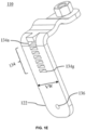
- Fig. 1B is a pictorial snapshot illustrating a side view of the first hanger 108a (hereinafter interchangeably referred to and designated as “the hanger 108").
- the first hanger 108 has the first bracket 110 (hereinafter interchangeably referred to and designated as “the bracket 110) and the first support arm 112 (hereinafter interchangeably referred to and designated as "the support arm 112).
- the bracket 110 have a vertical arm 122 and a horizontal arm 124.
- the vertical arm 122 is disposed at an angle with respect to the horizontal arm 124.
- the angle between the vertical arm 122 and the horizontal arm 124 is in a range of 60 degrees to 120 degrees.
- the angle between the vertical arm 122 and the horizontal arm 124 is 90 degrees.
- the horizontal arm 124 have a curved portion 126 forming a bump on an upper surface of the horizontal arm 124.
- the curved portion 126 is provided to accept cables (e.g., the cable 104) with smaller diameters when the hanger 108 is installed over the cables.
- the curved portion 126 is greater than 5 millimeters (mm).
- the curved portion 126 being greater than 5 mm allow the hanger 108 to accept a cable (e.g., the cable 104) having a diameter in a range of 3 mm to 32 mm.
- the curved portion 126 being greater than 5 mm allow the hanger 108 to accept a cable ( e.g., the cable 104) having a diameter of approximately 28 mm.
- the horizontal arm 124 have a distal end 124a with an arm fastener cavity 137.
- the distal end 124a is an end of the horizontal arm 124 that points away from the vertical arms 122.
- the vertical arm 122 and the horizontal arm 124 form a monolith structure.
- the bracket 108 having the vertical arm 122 and the horizontal arm 124 is fabricated by shaping a single sheet metal that is made up of a material such as, but not limited to, iron, aluminium, and the like. Aspects of the present disclosure are intended to have and/or otherwise cover any type of the material for the bracket 108 that eliminates the requirement for molds, without deviating from the scope of the present disclosure.
- the support arm 112 includes a first end 112a with a tab 138 and a second end 112b.
- the first end 112a is engaged with the vertical arm 122 by way of the tab 138 in an installed configuration of the hanger 108.
- the support arm 112 is substantially parallel to the horizontal arm 124 in the installed configuration of the hanger 108.
- the support arm 112 has a flat surface such that in the installed configuration of the hanger 108, an upper surface of the support arm 112 is substantially parallel to a bottom surface ( i.e., a flat bottom surface) of the horizontal arm 124.
- the support arm 112 have a curved portion (not shown) that is substantially similar to the curved portion 126 and curved in an opposite direction with respect to the curved portion 126. The curved portion of the support arm 112 facilitate a fit of the cable 104 within the bracket 110 in the installed configuration of the hanger 108.
- the second end 112b of the support arm 112 may have a support fastener cavity 140.
- the support fastener cavity 140 of the support arm 112 align with the arm fastener cavity 137 of the horizontal arm 124 such that, in the installed configuration of the hanger 108, the support arm 112 is attached to the horizontal arm 124 by way of the fastener 118.
- the fastener 118 is inserted through the support fastener cavity 140 of the support arm 112 and the arm fastener cavity 137 of the horizontal arm 24 and tightened by way of a nut 128.
- the vertical arm 122 have an adapter cavity 136 adapted to accept an adapter fastener 130 that is tightened by way of a nut 132.
- the nut 132 have inner threads and the adapter fastener 130 have outer threads such that the inner threads of the nut 132 are engaged with the outer threads of the adapter fastener 130 when the adapter fastener 130 is inserted into the adapter cavity 136 and screwed in the nut 132.
- the hanger 108 have an adapter 142 having a through hole 142a such that the through hole 142a of the adapter 142 is aligned with the adapter cavity 136 and the adapter fastener 130 is inserted through the through hole 142a of the adapter 142 and the adapter cavity 136 to be fastened with the nut 132.
- the optical fiber closure 106 is attached to the vertical arm 122 of the bracket 110.
- the adapter fastener 130 is adapted to tighten the optical fiber closure 106 with the vertical arm 122 of the bracket 110 of the hanger 108.
- the nut 128 is fixedly attached to a top surface of the horizontal arm 124.
- the nut 128 is fixedly attached over the arm fastener cavity 137 of the horizontal arm 124 such that an opening of the nut 128 is aligned with the arm fastener cavity 137 of the horizontal arm 124.
- Fig. 1C illustrates a side view of hanger 108 in accordance with another embodiment of the present disclosure.
- the nut 128 is fixedly attached to a top surface of the horizontal arm 124.
- the nut 128 is fixedly attached over the arm fastener cavity 137 of the horizontal arm 124 such that an opening of the nut 128 is aligned with the arm fastener cavity 137 of the horizontal arm 124.
- the fastener 118 is inserted through the support fastener cavity 140 of the support arm 112 and into the arm fastener cavity 137 of the horizontal arm 124 is tightened by way of the nut 128.
- the nut 128 is fixedly attached to the top surface of the horizontal arm 124 by way of welding.
- the nut 128 have inner threads (not shown) that facilitate the tightening of the fastener 118.
- the total height H of the hanger 108 having the fixedly attached nut 128 on the top surface of the horizontal arm 124 is 83 mm.
- a total width W of the hanger 108 having the support arm 112 installed on the bracket 110 i.e., having the tab 138) is 56 mm.
- Fig. 1D is a pictorial snapshot illustrating yet another side view of the hanger 108 in accordance with an embodiment of the present disclosure.
- the nut 128 is fixedly attached to a bottom surface of the support arm 112 by support fastener cavity 140 of the support arm 112 such that the opening of the nut 128 is aligned with the support fastener cavity 140 of the support arm 112.
- the fastener 118 inserted through the arm fastener cavity 137 of the horizontal arm 124 and into the support fastener cavity 140 of the support arm 112 is screwed by way of the nut 128.
- the nut 128 is fixedly attached to the bottom surface of the support arm 112 by way of welding.
- the nut 128 tightens the fastener 118 such that the horizontal arm 124 and the support arm 112 tightens on both sides of the cable 104 making the installation ergonomic and safe.
- the adapter cavity 136 is adapted to accept the adapter fastener 130 that is tightened by way of the nut 132.
- the nut 132 have inner threads and the adapter fastener 130 have outer threads such that the inner threads of the nut 132 are engaged with the outer threads of the adapter fastener 130 when the adapter fastener 130 is inserted into the adapter cavity 136 and screwed in the nut 132.
- Fig. 1E is a pictorial snapshot illustrating a side perspective view of the bracket 110 in accordance with an embodiment of the present disclosure.
- the vertical arm 122 has a plurality of slots 134 of which first through seventh slots 134a-134g are shown.
- the first through seventh slots 134a-134g is arranged in a vertically stacked orientation.
- each slot of the first through seventh slots 134a-134g is arranged in a way that each slot of the first through seventh slots 134a-134 g corresponds to a specific diameter.
- at least one slot of the first through seventh slots 134a-134g accept the tab 138 of the support arm 112 to make the installation ergonomic and safer.
- each slot of the first through seventh slots 134a-134g have a dimension (i.e., a width and a height) that closely imitates a dimension ( i.e., a width and a thickness) of the tab 138 of the support arm 112 such that by virtue of the dimensions of each slot of the first through seventh slots 134a-134g, the tab 138 of the support arm 112 can be inserted in a secure manner inside at least one slot of the of the first through seventh slots 134a-134g in the installed configuration of the hanger 108.
- the vertical arm 122 have the adapter cavity 136.
- the adapter cavity 136 is adapted to accept the adapter fastener 130 that is tightened by way of the nut 132
- the vertical arm 122 may have a width VW that is equal to 30 mm. Alternatively, the width VW may differ.
- Fig. 1F is a pictorial snapshot illustrating another side perspective view of the bracket 110 in accordance with an embodiment of the present disclosure.
- the distal end 124a of the horizontal arm 124 have the arm fastener cavity 137 aligned with the support fastener cavity 140 of the support arm 112 such that, in the installed configuration of the hanger 108, the support arm 112 is attached to the horizontal arm 124 by way of the fastener 118.
- the fastener 118 is inserted through the support fastener cavity 140 of the support arm 112 and into the arm fastener cavity 137 of the horizontal arm 124 and tightened by way of the nut 128.
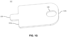
- Fig. 1G is a pictorial snapshot illustrating a top perspective view of the support arm 112 of the hanger 108 in accordance with an embodiment of the present disclosure.
- the support arm 112 have the first end 112a with the tab 138 extending substantially outwardly from the first end 112a such that the tab 138 is inserted in at least one slot of the first through seventh slots 134a-134g of the vertical arm 122 in the installed configuration of the hanger 108.
- the support arm 112 is engaged with the vertical arm 122 by way of the tab 138 such that the support arm 112 is substantially parallel to the horizontal arm 124.
- the support arm 112 may have the support fastener cavity 140 aligned with the arm fastener cavity 137 of the horizontal arm 124 such that, in the installed configuration of the hanger 108, the support arm 112 is attached to the horizontal arm 124 by way of the fastener 118. Specifically, the fastener 118 is inserted through the support fastener cavity 140 and the arm fastener cavity 137 of the horizontal arm 124 and tightened by way of the nut 128.
- the support arm 112 may have a substantially rectangular shape with substantially curved edges. Alternatively, the support arm 112 may have a different shape.
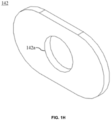
- Fig. 1H is a pictorial snapshot illustrating a side perspective view of the adapter 142 of the hanger 108 in accordance with an embodiment of the present disclosure.
- the adapter 142 is an oval shaped thin plate having a through hole 142a that is adapted to distribute a load of the threaded adapter fastener 130.
- the through hole 142a is provided at a center of the adapter 142 such that the through hole 142a is aligned with the adapter cavity 136 and the adapter fastener 130 is inserted through the through hole 142a and the adapter cavity 136 to be fastened with the nut 132.
- the adapter fastener 130 is adapted to tighten the optical fiber closure 106 with the hanger 108.
- the adapter 142 is made up of a material such as, but not limited to, a metal, a hardened plastic, and the like. Aspects of the present disclosure are intended to have and/or otherwise cover any type of the material for the adapter 142, without deviating from the scope of the present disclosure.
- Fig. 2 is a flowchart illustrating a method 200 for installing the hanger kit 102 over the cable 104 by mounting the optical fiber closure (106) aerially over the cable (104) in accordance with an embodiment of the present disclosure.
- the method 200 starts at step 202 and proceeds to step 204-210.
- step 202 the horizontal arm 124 of the bracket 110 is held over the cable 104.
- the support arm 112 is adjusted based on the diameter of the cable 104.
- the tab 138 provided at the first end 112a of the support arm 112 is inserted in at least one slot of the plurality of slots 134a-134g provided in the vertical arm 122 of the bracket 110.
- the fastener 118 is tightened to engage the horizontal arm 124 and the support arm 112 in the installed configuration of the hanger 108 such that the cable 104 is tightly held between the horizontal arm 124 of the bracket 110 on one side and the support arm 112 on the other side.
- the cable 104 is held between the curved portion 126 of the horizontal arm 124 of the bracket 110 on one side and the support arm 112 on the other side.
- the optical fiber closure 106 is attached to the vertical arm 122 of the bracket 110 by anyone of the adapter 142, the adapter fastener 130, and the nut 132, thereby enabling mounting of the optical fiber closure 106 on the cable 104.
- the step 210 is performed prior to the step 202 such that, prior to holding the horizontal arm 124 of the bracket 110 over the cable 104, the optical fiber closure 106 is attached to the vertical arm 122 of the bracket 110 to facilitate easy mounting of the optical fiber closure 106 on the cable 104.
- Fig. 3 is a flowchart illustrating a method for installing the hanger kit over the cable 104 by mounting the optical fiber closure aerially over the cable in accordance with an embodiment of the present disclosure.
- an optical fiber closure 106 is attached to the vertical arm 122 of the bracket 110 by an attachment.
- the attachment is any of an adapter 142, an adapter fastener 130, and a nut 132.
- the optical fiber closure (106) are mounted on the cable (104).
- the hanger kit 102 facilitates the mounting of optical fiber closure 106 on any cable having any diameter. Moreover, the hangers 108 of the hanger kit 102 tighten and compress the cable 104 on two points thus creating more friction and completely preventing the hangers 108 from rotating around the cable 104.
Landscapes
- Physics & Mathematics (AREA)
- General Physics & Mathematics (AREA)
- Optics & Photonics (AREA)
- Light Guides In General And Applications Therefor (AREA)
Abstract
Description
- Embodiments of the present disclosure relates to the field of mounting optical fiber apparatus, and more particularly to a hanger and a hanger kit to aerially mount a fiber optic enclosure.
- This application claims the benefit of
Indian Application No. 202211061031 titled "HANGER AND A HANGER KIT TO AERIALLY MOUNT A FIBER OPTIC ENCLOSURE" filed by the applicant on October 26, 2022 - Aerial routing configurations are commonly used to distribute fiber optic cables to various locations within a fiber optic network. In a typical aerial routing configuration, fiber optic cables are lashed to metal strands (e.g., metal wires or cables) that are routed aerially from power pole to power pole. At various locations throughout the fiber optic network, it is desirable to access optical fibers of the fiber optic cables (e.g., for splicing to drop cables). At typical access locations, cable jackets of the fiber optic cables are cut and/or removed to provide access to the optical fibers. The access locations are typically housed within sealed, re-enterable protective enclosures that frequently contain fiber optic components such as splice trays. In a typical application, a fiber optic cable is routed through a fiber optic enclosure and within the fiber optic enclosure one or more of the optical fibers is accessed for splicing to a drop cable. It is frequently desirable to aerially mount the fiber optic enclosures.
- To distribute fiber optic cables to various locations aerial routing is commonly used. Hanger kits allow aerial installation of optical fiber enclosures for the aerial routing of the optical fiber cables due to various reasons such as a need to make splices on aerial cables, a possible lack of poles or facades for fixing the optical fiber enclosures, geographical requirements that hinders typical installation (poles, facades, and manholes).
- Further, to provide splices in aerial telecommunication and CATV cables and splice enclosures mounted adjacent the cables to protect the splices. Typically, one or a bundle of aerial telecommunication cables are lashed to a messenger strand or cable that spans and is anchored to spaced apart supports such as telephone or utility poles.
- Prior art reference "
US9407080B2 - Another prior art reference "
US9377132B2 - Yet another prior art reference "
KR200457959Y1 - Yet another prior art reference "
US9939602B2 - While the prior arts provide various devices and systems that are known for hanging or securing a splice enclosure to a messenger strand, however such devices and systems tend to have multiple components that must be attached and aligned independently, and which may also present many loose parts that can be lost when in the air installing the device. Further, the above-mentioned solutions generally have a single compression point and can only be installed on cables having smaller diameters. Moreover, as the number of components in such solutions is on the higher side, therefore, the handling complexity and maintenance of such devices is higher.
- Therefore, in the light of the above-stated discussion, there is a need to overcome the above stated disadvantages by providing enhanced configurations for aerially mounting fiber optic enclosures. Thus, the present disclosure provides an alternative apparatus for aerial mounting the optical fiber closures.
- Embodiments of the present disclosure provide a system and method to mount an optical fiber closure aerially over the cable.
- According to the first aspect of the present disclosure, the hanger kit installed over a cable comprising a plurality of hangers. In particular, each hanger of the plurality of hangers includes a bracket having a vertical arm and a horizontal arm with a curved portion and a support arm having a first end and a second end. The first end is adapted to be engaged with the vertical arm such that the support arm is substantially parallel to the horizontal arm in an installed configuration of the hanger.
- According to the second aspect of the present disclosure, the vertical arm comprises a plurality of slots arranged in a vertically stacked orientation and the support arm comprises a tab extending substantially outwardly from the first end such that, in the install configuration, the tab is inserted in at least one slot of the plurality of slots.
- According to the third aspect of the present disclosure, the horizontal arm and the support arm comprise an arm fastener cavity and a support fastener cavity respectively.
- In accordance with an embodiment of the present disclosure, the curved portion (126) is greater than 5 millimeters (mm).
- In accordance with an embodiment of the present disclosure, an angle between the vertical arm (122) and the horizontal arm (124) is in a range of 60 degrees to 120 degrees.
- In accordance with an embodiment of the present disclosure, the bracket (110) comprising the vertical arm (122) and the horizontal arm (124) is a monolith structure.
- According to the fourth aspect of the present disclosure, a method for installing a an optical fiber closure by mounting hanger aerially over the cable comprising steps of holding a horizontal arm of a bracket of the hanger over a cable, adjusting a support arm of the hanger according to a diameter of the cable, inserting a tab provided at a first end of the support arm of the hanger in at least one slot of a plurality of slots provided in a vertical arm of the bracket and tightening a fastener to engage the horizontal arm and the support arm in an installed configuration of the hanger such that the cable is tightly held between the horizontal arm and the support arm.
- According to the fifth aspect of the present disclosure, the method further includes tightening the fastener to engage the horizontal arm and the support arm such that the cable is held between a curved portion of the horizontal arm on one side and the support arm on the other side.
- In accordance with an embodiment of the present disclosure, the method involves attaching an optical fiber closure to the vertical arm of the bracket by way of an adapter, an adapter fastener, and a nut, thereby enabling mounting of the optical fiber closure on the cable.
- In accordance with an embodiment of the present disclosure, the method involves welding a nut for the fastener to at least one of, the horizontal arm and the support arm.
- These and other aspects herein will be better appreciated and understood when considered in conjunction with the following description and the accompanying drawings. It should be understood, however, that the following descriptions are given by way of illustration and not of limitation. Many changes and modifications is made within the scope of the disclosure herein without departing from the spirit thereof.
- To describe the technical solutions in the embodiments of the present disclosure or in the prior art more clearly, the following briefly describes the accompanying drawings required for describing the embodiments or the prior art. Apparently, the accompanying drawings in the following description merely show some embodiments of the present disclosure, and a person of ordinary skill in the art can derive other implementations from these accompanying drawings without creative efforts. All of the embodiments or the implementations shall fall within the protection scope of the present disclosure.
-
Fig. 1A is a pictorial snapshot illustrating a schematic view of an installation of a hanger kit installed over a cable in accordance with an embodiment of the present disclosure; -
Fig. 1B is a pictorial snapshot illustrating a side view of the hanger in accordance with an embodiment of the present disclosure; -
Fig. 1C is a pictorial snapshot illustrating another side view of the hanger in accordance with an embodiment of the present disclosure; -
Fig. 1D is a pictorial snapshot illustrating yet another side view of the hanger in accordance with an embodiment of the present disclosure; -
Fig. 1E is a pictorial snapshot illustrating a side perspective view of a bracket in accordance with an embodiment of the present disclosure; -
Fig. 1F is a pictorial snapshot illustrating another side perspective view of the bracket in accordance with an embodiment of the present disclosure; -
Fig. 1G is a pictorial snapshot illustrating a top perspective view of a support arm of the hanger in accordance with an embodiment of the present disclosure; -
Fig. 1H is a pictorial snapshot illustrating a side perspective view of an adapter of the hanger in accordance with an embodiment of the present disclosure; -
Fig. 2 is a flow chart illustrating a method for installing the hanger kit over the cable in accordance with an embodiment of the present disclosure. -
Fig. 3 is a flowchart illustrating a method for installing the hanger kit over the cable by mounting the optical fiber closure aerially over the cable in accordance with an embodiment of the present disclosure. - The system and method are illustrated in the accompanying drawings, which like reference letters indicate corresponding parts in the various figures. It should be noted that the accompanying figure is intended to present illustrations of exemplary embodiments of the present disclosure. This figure is not intended to limit the scope of the present disclosure. It should also be noted that the accompanying figure is not necessarily drawn to scale.
- Those skilled in the art will be aware that the present disclosure is subject to variations and modifications other than those specifically described. It is to be understood that the present disclosure includes all such variations and modifications. The disclosure also includes all such steps, features, compositions and compounds referred to or indicated in this specification, individually or collectively, and any and all combinations of any or more of such steps or features.
- For convenience, before further description of the present disclosure, certain terms employed in the specification, and examples are collected here. These definitions should be read in the light of the remainder of the disclosure and understood as by a person of skill in the art. The terms used herein have the meanings recognized and known to those of skill in the art, however, for convenience and completeness, particular terms and their meanings are set forth below.
- The articles "a", "an" and "the" are used to refer to one or to more than one (i.e., to at least one) of the grammatical object of the article.
- The terms "comprise" and "comprising" are used in the inclusive, open sense, meaning that additional elements is included. It is not intended to be construed as "consists of only". Throughout this specification, unless the context requires otherwise the word "comprise", and variations such as "comprises" and "comprising", will be understood to imply the inclusion of a stated element or step or group of element or steps but not the exclusion of any other element or step or group of element or steps.
- The term "including" is used to mean "including but not limited to". "Including" and "including but not limited to" are used interchangeably.
- The term "the
hanger 108" as used hereinafter refers to both the first andsecond hangers 108a and 108b. - Term "the
bracket 110" as used hereinafter refers to both the first andsecond brackets - Term "the
support arm 112" as used hereinafter refers to both the first andsecond support arms - The structural and functional aspects of the
first hanger 108a, thefirst bracket 110, and thefirst support arm 112 apply to the second hanger 108b, thesecond bracket 114, and thesecond support arm 116, respectively. - Term "distal end" used herein refers to an end of the horizontal arm that points away from the vertical arm.
-
Fig. 1A is a pictorial snapshot illustrating a schematic view of aninstallation 100 of a hanger kit 102 installed over acable 104 in accordance with an embodiment of the present disclosure. In particular, the hanger kit 102 facilitates mounting anoptical fiber closure 106 aerially over thecable 104. The hanger kit 102 has one or more hangers of which first andsecond hangers 108a and 108b. It is noted that, thefirst hanger 108a and the second hanger 108b is structurally and functionally similar. Thefirst hanger 108a have afirst bracket 110 and afirst support arm 112. And, the second hanger 108b have asecond bracket 114 and asecond support arm 116. - In some aspects of the present disclosure, the first and
second brackets second support arms - Further, the first and
second brackets cable 104 by tightening the first andsecond support arms second fasteners second brackets cable 104 in an installed configuration of the hanger kit 102. Specifically, in the installed configuration of the hanger kit 102, thecable 104 is tightly held within the first andsecond brackets - The
optical fiber closure 106 is attached to first andsecond brackets optical fiber closure 106 on thecable 104. AlthoughFIG. 1 illustrates that the hanger kit 102 has two brackets (i.e., the first andsecond brackets 110 and 114) and corresponding two support arms (i.e., the first andsecond support arms 112 and 116), it will be apparent to a person skilled in the art that the scope of the present disclosure is not limited to it. - In various other aspects of the present disclosure, the hanger kit 102 have more than two brackets and support arms in a way that each bracket has a corresponding support arm, without deviating from the scope of the present disclosure. In such a scenario, each bracket and each support arm is adapted to be used in a manner similar to the first and
second brackets second support arms -
Fig. 1B is a pictorial snapshot illustrating a side view of thefirst hanger 108a (hereinafter interchangeably referred to and designated as "thehanger 108"). In particular, thefirst hanger 108 has the first bracket 110 (hereinafter interchangeably referred to and designated as "the bracket 110) and the first support arm 112 (hereinafter interchangeably referred to and designated as "the support arm 112). - In particular, the
bracket 110 have avertical arm 122 and ahorizontal arm 124. In some aspects of the present disclosure, thevertical arm 122 is disposed at an angle with respect to thehorizontal arm 124. In one embodiment, the angle between thevertical arm 122 and thehorizontal arm 124 is in a range of 60 degrees to 120 degrees. Alternatively, the angle between thevertical arm 122 and thehorizontal arm 124 is 90 degrees. - The
horizontal arm 124 have acurved portion 126 forming a bump on an upper surface of thehorizontal arm 124. In particular, thecurved portion 126 is provided to accept cables (e.g., the cable 104) with smaller diameters when thehanger 108 is installed over the cables. - In some aspects of the present disclosure, the
curved portion 126 is greater than 5 millimeters (mm). Thecurved portion 126 being greater than 5 mm allow thehanger 108 to accept a cable (e.g., the cable 104) having a diameter in a range of 3 mm to 32 mm. Moreover, thecurved portion 126 being greater than 5 mm allow thehanger 108 to accept a cable (e.g., the cable 104) having a diameter of approximately 28 mm. - In some aspects of the present disclosure, the
horizontal arm 124 have adistal end 124a with anarm fastener cavity 137. Thedistal end 124a is an end of thehorizontal arm 124 that points away from thevertical arms 122. - In some aspects of the present disclosure, the
vertical arm 122 and thehorizontal arm 124 form a monolith structure. - Alternatively, the
bracket 108 having thevertical arm 122 and thehorizontal arm 124 is fabricated by shaping a single sheet metal that is made up of a material such as, but not limited to, iron, aluminium, and the like. Aspects of the present disclosure are intended to have and/or otherwise cover any type of the material for thebracket 108 that eliminates the requirement for molds, without deviating from the scope of the present disclosure. - The
support arm 112 includes afirst end 112a with atab 138 and asecond end 112b. In particular, thefirst end 112a is engaged with thevertical arm 122 by way of thetab 138 in an installed configuration of thehanger 108. Moreover, when thesupport arm 112 is engaged with thevertical arm 122 by way of thetab 138 provided at thefirst end 112a, thesupport arm 112 is substantially parallel to thehorizontal arm 124 in the installed configuration of thehanger 108. - In some aspects of the present disclosure, the
support arm 112 has a flat surface such that in the installed configuration of thehanger 108, an upper surface of thesupport arm 112 is substantially parallel to a bottom surface (i.e., a flat bottom surface) of thehorizontal arm 124. Alternatively, thesupport arm 112 have a curved portion (not shown) that is substantially similar to thecurved portion 126 and curved in an opposite direction with respect to thecurved portion 126. The curved portion of thesupport arm 112 facilitate a fit of thecable 104 within thebracket 110 in the installed configuration of thehanger 108. - In accordance with an embodiment of the present disclosure, the
second end 112b of thesupport arm 112 may have asupport fastener cavity 140. Particularly, thesupport fastener cavity 140 of thesupport arm 112 align with thearm fastener cavity 137 of thehorizontal arm 124 such that, in the installed configuration of thehanger 108, thesupport arm 112 is attached to thehorizontal arm 124 by way of thefastener 118. Moreover, thefastener 118 is inserted through thesupport fastener cavity 140 of thesupport arm 112 and thearm fastener cavity 137 of the horizontal arm 24 and tightened by way of anut 128. - In accordance with an embodiment of the present disclosure, the
vertical arm 122 have anadapter cavity 136 adapted to accept anadapter fastener 130 that is tightened by way of anut 132. In particular, thenut 132 have inner threads and theadapter fastener 130 have outer threads such that the inner threads of thenut 132 are engaged with the outer threads of theadapter fastener 130 when theadapter fastener 130 is inserted into theadapter cavity 136 and screwed in thenut 132. - In accordance with another embodiment of the present disclosure, the
hanger 108 have anadapter 142 having a throughhole 142a such that the throughhole 142a of theadapter 142 is aligned with theadapter cavity 136 and theadapter fastener 130 is inserted through the throughhole 142a of theadapter 142 and theadapter cavity 136 to be fastened with thenut 132. - In accordance with an embodiment of the present disclosure, the
optical fiber closure 106 is attached to thevertical arm 122 of thebracket 110. Specifically, theadapter fastener 130 is adapted to tighten theoptical fiber closure 106 with thevertical arm 122 of thebracket 110 of thehanger 108. - In accordance with an embodiment of the present disclosure, the
nut 128 is fixedly attached to a top surface of thehorizontal arm 124. In particular, thenut 128 is fixedly attached over thearm fastener cavity 137 of thehorizontal arm 124 such that an opening of thenut 128 is aligned with thearm fastener cavity 137 of thehorizontal arm 124. -
Fig. 1C illustrates a side view ofhanger 108 in accordance with another embodiment of the present disclosure. In particular, thenut 128 is fixedly attached to a top surface of thehorizontal arm 124. Moreover, thenut 128 is fixedly attached over thearm fastener cavity 137 of thehorizontal arm 124 such that an opening of thenut 128 is aligned with thearm fastener cavity 137 of thehorizontal arm 124. Thefastener 118 is inserted through thesupport fastener cavity 140 of thesupport arm 112 and into thearm fastener cavity 137 of thehorizontal arm 124 is tightened by way of thenut 128. In some aspects of the present disclosure, thenut 128 is fixedly attached to the top surface of thehorizontal arm 124 by way of welding. Alternatively, thenut 128 have inner threads (not shown) that facilitate the tightening of thefastener 118. - In accordance with an embodiment of the present disclosure, the total height H of the
hanger 108 having the fixedly attachednut 128 on the top surface of thehorizontal arm 124 is 83 mm. And, a total width W of thehanger 108 having thesupport arm 112 installed on the bracket 110 (i.e., having the tab 138) is 56 mm. -
Fig. 1D is a pictorial snapshot illustrating yet another side view of thehanger 108 in accordance with an embodiment of the present disclosure. Thenut 128 is fixedly attached to a bottom surface of thesupport arm 112 bysupport fastener cavity 140 of thesupport arm 112 such that the opening of thenut 128 is aligned with thesupport fastener cavity 140 of thesupport arm 112. Thus, thefastener 118 inserted through thearm fastener cavity 137 of thehorizontal arm 124 and into thesupport fastener cavity 140 of thesupport arm 112 is screwed by way of thenut 128. - In an aspect of the present disclosure, the
nut 128 is fixedly attached to the bottom surface of thesupport arm 112 by way of welding. In particular, thenut 128 tightens thefastener 118 such that thehorizontal arm 124 and thesupport arm 112 tightens on both sides of thecable 104 making the installation ergonomic and safe. Moreover, theadapter cavity 136 is adapted to accept theadapter fastener 130 that is tightened by way of thenut 132. As discussed, thenut 132 have inner threads and theadapter fastener 130 have outer threads such that the inner threads of thenut 132 are engaged with the outer threads of theadapter fastener 130 when theadapter fastener 130 is inserted into theadapter cavity 136 and screwed in thenut 132. -
Fig. 1E is a pictorial snapshot illustrating a side perspective view of thebracket 110 in accordance with an embodiment of the present disclosure. In particular, thevertical arm 122 has a plurality ofslots 134 of which first throughseventh slots 134a-134g are shown. The first throughseventh slots 134a-134g is arranged in a vertically stacked orientation. In particular, each slot of the first throughseventh slots 134a-134g is arranged in a way that each slot of the first throughseventh slots 134a-134 g corresponds to a specific diameter. Further, in the installed configuration of thehanger 108, at least one slot of the first throughseventh slots 134a-134g accept thetab 138 of thesupport arm 112 to make the installation ergonomic and safer. - In some aspects of the present disclosure, each slot of the first through
seventh slots 134a-134g have a dimension (i.e., a width and a height) that closely imitates a dimension (i.e., a width and a thickness) of thetab 138 of thesupport arm 112 such that by virtue of the dimensions of each slot of the first throughseventh slots 134a-134g, thetab 138 of thesupport arm 112 can be inserted in a secure manner inside at least one slot of the of the first throughseventh slots 134a-134g in the installed configuration of thehanger 108. Further, thevertical arm 122 have theadapter cavity 136. Theadapter cavity 136 is adapted to accept theadapter fastener 130 that is tightened by way of thenut 132 - In one aspect of the present disclosure, the
vertical arm 122 may have a width VW that is equal to 30 mm. Alternatively, the width VW may differ. -
Fig. 1F is a pictorial snapshot illustrating another side perspective view of thebracket 110 in accordance with an embodiment of the present disclosure. Thedistal end 124a of thehorizontal arm 124 have thearm fastener cavity 137 aligned with thesupport fastener cavity 140 of thesupport arm 112 such that, in the installed configuration of thehanger 108, thesupport arm 112 is attached to thehorizontal arm 124 by way of thefastener 118. In other words, thefastener 118 is inserted through thesupport fastener cavity 140 of thesupport arm 112 and into thearm fastener cavity 137 of thehorizontal arm 124 and tightened by way of thenut 128. -
Fig. 1G is a pictorial snapshot illustrating a top perspective view of thesupport arm 112 of thehanger 108 in accordance with an embodiment of the present disclosure. Thesupport arm 112 have thefirst end 112a with thetab 138 extending substantially outwardly from thefirst end 112a such that thetab 138 is inserted in at least one slot of the first throughseventh slots 134a-134g of thevertical arm 122 in the installed configuration of thehanger 108. In the installed configuration of thehanger 108, thesupport arm 112 is engaged with thevertical arm 122 by way of thetab 138 such that thesupport arm 112 is substantially parallel to thehorizontal arm 124. Further, thesupport arm 112 may have thesupport fastener cavity 140 aligned with thearm fastener cavity 137 of thehorizontal arm 124 such that, in the installed configuration of thehanger 108, thesupport arm 112 is attached to thehorizontal arm 124 by way of thefastener 118. Specifically, thefastener 118 is inserted through thesupport fastener cavity 140 and thearm fastener cavity 137 of thehorizontal arm 124 and tightened by way of thenut 128. - In some aspects of the present disclosure, the
support arm 112 may have a substantially rectangular shape with substantially curved edges. Alternatively, thesupport arm 112 may have a different shape. -
Fig. 1H is a pictorial snapshot illustrating a side perspective view of theadapter 142 of thehanger 108 in accordance with an embodiment of the present disclosure. Theadapter 142 is an oval shaped thin plate having a throughhole 142a that is adapted to distribute a load of the threadedadapter fastener 130. In particular, the throughhole 142a is provided at a center of theadapter 142 such that the throughhole 142a is aligned with theadapter cavity 136 and theadapter fastener 130 is inserted through the throughhole 142a and theadapter cavity 136 to be fastened with thenut 132. - In accordance with an embodiment of the present disclosure, the
adapter fastener 130 is adapted to tighten theoptical fiber closure 106 with thehanger 108. In particular, theadapter 142 is made up of a material such as, but not limited to, a metal, a hardened plastic, and the like. Aspects of the present disclosure are intended to have and/or otherwise cover any type of the material for theadapter 142, without deviating from the scope of the present disclosure. -
Fig. 2 is a flowchart illustrating amethod 200 for installing the hanger kit 102 over thecable 104 by mounting the optical fiber closure (106) aerially over the cable (104) in accordance with an embodiment of the present disclosure. Themethod 200 starts atstep 202 and proceeds to step 204-210. - At
step 202, thehorizontal arm 124 of thebracket 110 is held over thecable 104. - At
step 204, thesupport arm 112 is adjusted based on the diameter of thecable 104. - At
step 206, thetab 138 provided at thefirst end 112a of thesupport arm 112 is inserted in at least one slot of the plurality ofslots 134a-134g provided in thevertical arm 122 of thebracket 110. - At
step 208, thefastener 118 is tightened to engage thehorizontal arm 124 and thesupport arm 112 in the installed configuration of thehanger 108 such that thecable 104 is tightly held between thehorizontal arm 124 of thebracket 110 on one side and thesupport arm 112 on the other side. - In particular, the
cable 104 is held between thecurved portion 126 of thehorizontal arm 124 of thebracket 110 on one side and thesupport arm 112 on the other side. - At
step 210, theoptical fiber closure 106 is attached to thevertical arm 122 of thebracket 110 by anyone of theadapter 142, theadapter fastener 130, and thenut 132, thereby enabling mounting of theoptical fiber closure 106 on thecable 104. - In some aspects of the present disclosure, the
step 210 is performed prior to thestep 202 such that, prior to holding thehorizontal arm 124 of thebracket 110 over thecable 104, theoptical fiber closure 106 is attached to thevertical arm 122 of thebracket 110 to facilitate easy mounting of theoptical fiber closure 106 on thecable 104. -
Fig. 3 is a flowchart illustrating a method for installing the hanger kit over thecable 104 by mounting the optical fiber closure aerially over the cable in accordance with an embodiment of the present disclosure. - At
step 305, anoptical fiber closure 106 is attached to thevertical arm 122 of thebracket 110 by an attachment. The attachment is any of anadapter 142, anadapter fastener 130, and anut 132.
Atstep 310 the optical fiber closure (106) are mounted on the cable (104). - Advantageously, the hanger kit 102 facilitates the mounting of
optical fiber closure 106 on any cable having any diameter. Moreover, thehangers 108 of the hanger kit 102 tighten and compress thecable 104 on two points thus creating more friction and completely preventing thehangers 108 from rotating around thecable 104. - The foregoing descriptions of specific embodiments of the present technology have been presented for purposes of illustration and description. They are not intended to be exhaustive or to limit the present technology to the precise forms disclosed, and obviously many modifications and variations are possible in light of the above teaching. The embodiments were chosen and described in order to best explain the principles of the present technology and its practical application, to thereby enable others skilled in the art to best utilize the present technology and various embodiments with various modifications as are suited to the particular use contemplated. It is understood that various omissions and substitutions of equivalents are contemplated as circumstance may suggest or render expedient, but such are intended to cover the application or implementation without departing from the spirit or scope of the claims of the present technology.
- In a case that no conflict occurs, the embodiments in the present disclosure and the features in the embodiments is mutually combined. The foregoing descriptions are merely specific implementations of the present disclosure, but are not intended to limit the protection scope of the present disclosure. Any variation or replacement readily figured out by a person skilled in the art within the technical scope disclosed in the present disclosure shall fall within the protection scope of the present disclosure. Therefore, the protection scope of the present disclosure shall be subject to the protection scope of the claims.
Claims (15)
- A hanger (108) to mount an optical fiber closure (106) aerially over the cable (104), characterized in that:a bracket (110) witha vertical arm (122) with a plurality of slots (134) arranged in a vertically stacked orientation;a horizontal arm (124) with a curved portion (126); anda support arm (112) havingwherein the first end (112a) is adapted to be engaged with the vertical arm (122) such that the support arm (112) is substantially parallel to the horizontal arm (124) in an installed configuration of the hanger (108); and wherein the cable (104) is held between the curved portion (126) of the horizontal arm (124) on one side and the support arm (112) on other side.a first end (112a) and a second end (112b),a tab (138) extending substantially outwardly from the first end (112a) operably configured to be inserted in at least one slot of the plurality of slots (134);
- The hanger (108) as claimed in claim 1, wherein the horizontal arm (124) and the support arm (112) comprises an arm fastener cavity (137) and a support fastener cavity (140).
- The hanger (108) as claimed in claim 1, wherein the curved portion (126) is greater than 5 millimeters (mm).
- The hanger (108) as claimed in claim 1, wherein an angle between the vertical arm (122) and the horizontal arm (124) is in a range of 60 degrees to 120 degrees.
- The hanger (108) as claimed in claim 1, wherein the bracket (110) comprising the vertical arm (122) and the horizontal arm (124) is a monolith structure.
- A hanger kit (102) installed over a cable (104) to mount an optical fiber closure (106) aerially over the cable (104), wherein the hanger kit (102) comprising:
a plurality of hangers (108), wherein each hanger of the plurality of hangers (108) comprising:a bracket (110) havinga vertical arm (122) with a plurality of slots (134) arranged in a vertically stacked orientation;a horizontal arm (124) with a curved portion (126); anda support arm (112) havingwherein the first end (112a) is adapted to be engaged with the vertical arm (122) such that the support arm (112) is substantially parallel to the horizontal arm (124) in an installed configuration of the hanger (108); and wherein the cable (104) is held between the curved portion (126) of the horizontal arm (124) on one side and the support arm (112) on other side.a first end (112a) and a second end (112b),a tab (138) extending substantially outwardly from the first end (112a) operably configured to be inserted in at least one slot of the plurality of slots (134); - The hanger kit (102) as claimed in claim 6, wherein the horizontal arm (124) and the support arm (112) comprising an arm fastener cavity (137) and a support fastener cavity (140).
- The hanger kit (102) as claimed in claim 6, wherein the curved portion (126) is greater than 5 millimeters (mm).
- The hanger kit (102) as claimed in claim 6, wherein an angle between the vertical arm (122) and the horizontal arm (124) is in a range of 60 degrees to 120 degrees.
- The hanger kit (102) as claimed in claim 7, wherein the bracket (110) comprising the vertical arm (122) and the horizontal arm (103) is a monolith structure.
- A method (200) for installing a hanger (108) over a cable (104) to mount an optical fiber closure (106) aerially over the cable (104), characterized in that steps of:holding a horizontal arm (124) of a bracket (110) of the hanger (108) over a cable (104);adjusting a support arm (112) of the hanger (108) according to a diameter of the cable (104);inserting a tab (138) provided at a first end (112a) of the support arm (112) of the hanger (108) in at least one slot of a plurality of slots (134) provided in a vertical arm (122) of the bracket (110); andtightening a fastener (118) to engage the horizontal arm (124) and the support arm (112) in an installed configuration of the hanger (108) such that the cable (104) is tightly held between the horizontal arm (124) and the support arm (112);wherein the first end (112a) is adapted to be engaged with the vertical arm (122) such that the support arm (112) is substantially parallel to the horizontal arm (124) in an installed configuration of the hanger (108).
- The method (200) as claimed in claim 11, wherein the method (200) comprises a step of tightening the fastener (118) to engage the horizontal arm (124) and the support arm (112).
- The method (200) as claimed in claim 11, wherein the cable (104) is held between a curved portion (126) of the horizontal arm (124) on one side and the support arm (112) on other side.
- The method (200) as claimed in claim 11, wherein the method further comprisingattaching an optical fiber closure (106) to the vertical arm (122) of the bracket (110) by an attachment; andenabling mounting of the optical fiber closure (106) on the cable (104)wherein the attachment is any of an adapter (142), an adapter fastener (130), and a nut (132).
- The method (200) as claimed in claim 13, the method comprises welding a nut (128) for the fastener (118) to at least one of, the horizontal arm (124) and the support arm (112).
Applications Claiming Priority (1)
| Application Number | Priority Date | Filing Date | Title |
|---|---|---|---|
| IN202211061031 | 2022-10-26 |
Publications (2)
| Publication Number | Publication Date |
|---|---|
| EP4361695A1 true EP4361695A1 (en) | 2024-05-01 |
| EP4361695B1 EP4361695B1 (en) | 2026-02-04 |
Family
ID=87047951
Family Applications (1)
| Application Number | Title | Priority Date | Filing Date |
|---|---|---|---|
| EP23181399.9A Active EP4361695B1 (en) | 2022-10-26 | 2023-06-26 | Hanger and a hanger kit to aerially mount a fiber optic enclosure |
Country Status (1)
| Country | Link |
|---|---|
| EP (1) | EP4361695B1 (en) |
Citations (9)
| Publication number | Priority date | Publication date | Assignee | Title |
|---|---|---|---|---|
| US3415474A (en) * | 1966-10-21 | 1968-12-10 | Orlan C. Kindorf | Hanger for insulated pipe |
| US3701835A (en) * | 1971-10-12 | 1972-10-31 | Northern Electric Co | Multiple conductor cable terminal |
| DE7904314U1 (en) * | 1979-02-16 | 1979-05-17 | Siemens Ag, 1000 Berlin Und 8000 Muenchen | Fastening element made of tape-shaped material for fastening cable sleeves to suspension ropes |
| KR200457959Y1 (en) | 2009-10-19 | 2012-01-16 | 빛샘전자주식회사 | Optical cable connector |
| US20130236141A1 (en) * | 2012-03-09 | 2013-09-12 | 3M Innovative Properties Company | Optical cable connection closure |
| US9052038B2 (en) * | 2013-06-13 | 2015-06-09 | Mueller International, Llc | Sway brace retaining clip |
| US9377132B2 (en) | 2014-07-31 | 2016-06-28 | Commscope Technologies Llc | Enclosure hanger assembly and cable management system |
| US9407080B2 (en) | 2011-01-07 | 2016-08-02 | Commscope Technologies Llc | Hanger assemblies and cabling management systems and methods including the same |
| US9939602B2 (en) | 2014-12-09 | 2018-04-10 | Commscope Technologies Llc | Mounting system and kit for aerial mounting of a fiber optic enclosure |
-
2023
- 2023-06-26 EP EP23181399.9A patent/EP4361695B1/en active Active
Patent Citations (9)
| Publication number | Priority date | Publication date | Assignee | Title |
|---|---|---|---|---|
| US3415474A (en) * | 1966-10-21 | 1968-12-10 | Orlan C. Kindorf | Hanger for insulated pipe |
| US3701835A (en) * | 1971-10-12 | 1972-10-31 | Northern Electric Co | Multiple conductor cable terminal |
| DE7904314U1 (en) * | 1979-02-16 | 1979-05-17 | Siemens Ag, 1000 Berlin Und 8000 Muenchen | Fastening element made of tape-shaped material for fastening cable sleeves to suspension ropes |
| KR200457959Y1 (en) | 2009-10-19 | 2012-01-16 | 빛샘전자주식회사 | Optical cable connector |
| US9407080B2 (en) | 2011-01-07 | 2016-08-02 | Commscope Technologies Llc | Hanger assemblies and cabling management systems and methods including the same |
| US20130236141A1 (en) * | 2012-03-09 | 2013-09-12 | 3M Innovative Properties Company | Optical cable connection closure |
| US9052038B2 (en) * | 2013-06-13 | 2015-06-09 | Mueller International, Llc | Sway brace retaining clip |
| US9377132B2 (en) | 2014-07-31 | 2016-06-28 | Commscope Technologies Llc | Enclosure hanger assembly and cable management system |
| US9939602B2 (en) | 2014-12-09 | 2018-04-10 | Commscope Technologies Llc | Mounting system and kit for aerial mounting of a fiber optic enclosure |
Also Published As
| Publication number | Publication date |
|---|---|
| EP4361695B1 (en) | 2026-02-04 |
Similar Documents
| Publication | Publication Date | Title |
|---|---|---|
| US20220091355A1 (en) | Fiber optic cable fixation device and fiber optic cable mounting system comprising same | |
| EP2508928B1 (en) | Enclosure for telecommunications cables, with removable organizer | |
| US7903924B2 (en) | Connector for splicing and hanging cable trays | |
| US6629675B1 (en) | Cable management apparatus and method | |
| EP0851254A1 (en) | Routing and storage apparatus for optical fibers | |
| US9939602B2 (en) | Mounting system and kit for aerial mounting of a fiber optic enclosure | |
| US20200241229A1 (en) | Cable fixation devices and methods | |
| US20160154181A1 (en) | Apparatus and method for splicing all-dielectric self-supporting fiber optic cable | |
| US8280215B2 (en) | Multifiber loose buffer receiving element for a distributing device for optical waveguides | |
| US9377132B2 (en) | Enclosure hanger assembly and cable management system | |
| US20160033722A1 (en) | Bracket for Securing Multiple Fiber Optic Cables to a Termination Box | |
| US9465180B2 (en) | Strain relief clamp | |
| US9790051B2 (en) | Conductor spool and optical fiber / electrical composite cable with conductor spool assembly | |
| EP4361695B1 (en) | Hanger and a hanger kit to aerially mount a fiber optic enclosure | |
| US11243368B1 (en) | Fiber optic cable clamp | |
| US5970199A (en) | Frame for supporting fiber optic cable splices | |
| US20100061686A1 (en) | Sleeve for optical waveguide cables | |
| US20060198593A1 (en) | Fiber optic cable and optical ground wire coil storage and splice enclosure mounting bracket | |
| EP4028814A1 (en) | Clamp for engaging objects having different exterior dimensions, and a cable management system including such a clamp | |
| EP4028813A1 (en) | Cable management system for a splice enclosure, and a splice enclosure with a cable management system | |
| US20060275010A1 (en) | Support Fixture and Method for Supporting Subscriber Specific Fiber Optic Drop Wire | |
| EP2506054A1 (en) | Optical fibre underground storage box | |
| US20190146173A1 (en) | Support structure for an optical fiber cable | |
| JP4276731B2 (en) | Cable wiring method and wiring device | |
| JPH11202136A (en) | Routing and storage device for optical fiber |
Legal Events
| Date | Code | Title | Description |
|---|---|---|---|
| PUAI | Public reference made under article 153(3) epc to a published international application that has entered the european phase |
Free format text: ORIGINAL CODE: 0009012 |
|
| STAA | Information on the status of an ep patent application or granted ep patent |
Free format text: STATUS: THE APPLICATION HAS BEEN PUBLISHED |
|
| AK | Designated contracting states |
Kind code of ref document: A1 Designated state(s): AL AT BE BG CH CY CZ DE DK EE ES FI FR GB GR HR HU IE IS IT LI LT LU LV MC ME MK MT NL NO PL PT RO RS SE SI SK SM TR |
|
| STAA | Information on the status of an ep patent application or granted ep patent |
Free format text: STATUS: REQUEST FOR EXAMINATION WAS MADE |
|
| 17P | Request for examination filed |
Effective date: 20241031 |
|
| RBV | Designated contracting states (corrected) |
Designated state(s): AL AT BE BG CH CY CZ DE DK EE ES FI FR GB GR HR HU IE IS IT LI LT LU LV MC ME MK MT NL NO PL PT RO RS SE SI SK SM TR |
|
| GRAP | Despatch of communication of intention to grant a patent |
Free format text: ORIGINAL CODE: EPIDOSNIGR1 |
|
| STAA | Information on the status of an ep patent application or granted ep patent |
Free format text: STATUS: GRANT OF PATENT IS INTENDED |
|
| INTG | Intention to grant announced |
Effective date: 20251117 |
|
| GRAS | Grant fee paid |
Free format text: ORIGINAL CODE: EPIDOSNIGR3 |
|
| GRAA | (expected) grant |
Free format text: ORIGINAL CODE: 0009210 |
|
| STAA | Information on the status of an ep patent application or granted ep patent |
Free format text: STATUS: THE PATENT HAS BEEN GRANTED |
|
| AK | Designated contracting states |
Kind code of ref document: B1 Designated state(s): AL AT BE BG CH CY CZ DE DK EE ES FI FR GB GR HR HU IE IS IT LI LT LU LV MC ME MK MT NL NO PL PT RO RS SE SI SK SM TR |
|
| REG | Reference to a national code |
Ref country code: CH Ref legal event code: F10 Free format text: ST27 STATUS EVENT CODE: U-0-0-F10-F00 (AS PROVIDED BY THE NATIONAL OFFICE) Effective date: 20260204 Ref country code: GB Ref legal event code: FG4D |
|
| REG | Reference to a national code |
Ref country code: IE Ref legal event code: FG4D |
|
| REG | Reference to a national code |
Ref country code: DE Ref legal event code: R096 Ref document number: 602023011489 Country of ref document: DE |
|
| P01 | Opt-out of the competence of the unified patent court (upc) registered |
Free format text: CASE NUMBER: UPC_APP_0004298_4361695/2026 Effective date: 20260206 |
|
| REG | Reference to a national code |
Ref country code: NL Ref legal event code: MP Effective date: 20260204 |
|
| PG25 | Lapsed in a contracting state [announced via postgrant information from national office to epo] |
Ref country code: RS Free format text: LAPSE BECAUSE OF FAILURE TO SUBMIT A TRANSLATION OF THE DESCRIPTION OR TO PAY THE FEE WITHIN THE PRESCRIBED TIME-LIMIT Effective date: 20260504 |
|
| PG25 | Lapsed in a contracting state [announced via postgrant information from national office to epo] |
Ref country code: ES Free format text: LAPSE BECAUSE OF FAILURE TO SUBMIT A TRANSLATION OF THE DESCRIPTION OR TO PAY THE FEE WITHIN THE PRESCRIBED TIME-LIMIT Effective date: 20260204 |
|
| PG25 | Lapsed in a contracting state [announced via postgrant information from national office to epo] |
Ref country code: PL Free format text: LAPSE BECAUSE OF FAILURE TO SUBMIT A TRANSLATION OF THE DESCRIPTION OR TO PAY THE FEE WITHIN THE PRESCRIBED TIME-LIMIT Effective date: 20260204 |
|
| PG25 | Lapsed in a contracting state [announced via postgrant information from national office to epo] |
Ref country code: GR Free format text: LAPSE BECAUSE OF FAILURE TO SUBMIT A TRANSLATION OF THE DESCRIPTION OR TO PAY THE FEE WITHIN THE PRESCRIBED TIME-LIMIT Effective date: 20260505 |
|
| REG | Reference to a national code |
Ref country code: LT Ref legal event code: MG9D |
|
| PG25 | Lapsed in a contracting state [announced via postgrant information from national office to epo] |
Ref country code: LT Free format text: LAPSE BECAUSE OF FAILURE TO SUBMIT A TRANSLATION OF THE DESCRIPTION OR TO PAY THE FEE WITHIN THE PRESCRIBED TIME-LIMIT Effective date: 20260204 |
|
| PG25 | Lapsed in a contracting state [announced via postgrant information from national office to epo] |
Ref country code: NO Free format text: LAPSE BECAUSE OF FAILURE TO SUBMIT A TRANSLATION OF THE DESCRIPTION OR TO PAY THE FEE WITHIN THE PRESCRIBED TIME-LIMIT Effective date: 20260504 |
|
| PG25 | Lapsed in a contracting state [announced via postgrant information from national office to epo] |
Ref country code: AT Free format text: LAPSE BECAUSE OF FAILURE TO SUBMIT A TRANSLATION OF THE DESCRIPTION OR TO PAY THE FEE WITHIN THE PRESCRIBED TIME-LIMIT Effective date: 20260204 Ref country code: FI Free format text: LAPSE BECAUSE OF FAILURE TO SUBMIT A TRANSLATION OF THE DESCRIPTION OR TO PAY THE FEE WITHIN THE PRESCRIBED TIME-LIMIT Effective date: 20260204 Ref country code: SE Free format text: LAPSE BECAUSE OF FAILURE TO SUBMIT A TRANSLATION OF THE DESCRIPTION OR TO PAY THE FEE WITHIN THE PRESCRIBED TIME-LIMIT Effective date: 20260204 |
|
| REG | Reference to a national code |
Ref country code: AT Ref legal event code: MK05 Ref document number: 1884351 Country of ref document: AT Kind code of ref document: T Effective date: 20260204 |
|
| PG25 | Lapsed in a contracting state [announced via postgrant information from national office to epo] |
Ref country code: HR Free format text: LAPSE BECAUSE OF FAILURE TO SUBMIT A TRANSLATION OF THE DESCRIPTION OR TO PAY THE FEE WITHIN THE PRESCRIBED TIME-LIMIT Effective date: 20260204 |
|
| PG25 | Lapsed in a contracting state [announced via postgrant information from national office to epo] |
Ref country code: IS Free format text: LAPSE BECAUSE OF FAILURE TO SUBMIT A TRANSLATION OF THE DESCRIPTION OR TO PAY THE FEE WITHIN THE PRESCRIBED TIME-LIMIT Effective date: 20260604 Ref country code: PT Free format text: LAPSE BECAUSE OF FAILURE TO SUBMIT A TRANSLATION OF THE DESCRIPTION OR TO PAY THE FEE WITHIN THE PRESCRIBED TIME-LIMIT Effective date: 20260605 |
|
| PG25 | Lapsed in a contracting state [announced via postgrant information from national office to epo] |
Ref country code: NL Free format text: LAPSE BECAUSE OF FAILURE TO SUBMIT A TRANSLATION OF THE DESCRIPTION OR TO PAY THE FEE WITHIN THE PRESCRIBED TIME-LIMIT Effective date: 20260204 |
|
| PG25 | Lapsed in a contracting state [announced via postgrant information from national office to epo] |
Ref country code: LV Free format text: LAPSE BECAUSE OF FAILURE TO SUBMIT A TRANSLATION OF THE DESCRIPTION OR TO PAY THE FEE WITHIN THE PRESCRIBED TIME-LIMIT Effective date: 20260204 |
|
| PG25 | Lapsed in a contracting state [announced via postgrant information from national office to epo] |
Ref country code: BG Free format text: LAPSE BECAUSE OF FAILURE TO SUBMIT A TRANSLATION OF THE DESCRIPTION OR TO PAY THE FEE WITHIN THE PRESCRIBED TIME-LIMIT Effective date: 20260204 |