EP4361514A1 - Air-conditioning control device and air conditioner - Google Patents
Air-conditioning control device and air conditioner Download PDFInfo
- Publication number
- EP4361514A1 EP4361514A1 EP21947185.1A EP21947185A EP4361514A1 EP 4361514 A1 EP4361514 A1 EP 4361514A1 EP 21947185 A EP21947185 A EP 21947185A EP 4361514 A1 EP4361514 A1 EP 4361514A1
- Authority
- EP
- European Patent Office
- Prior art keywords
- air
- comfort
- occupant
- conditioning
- information
- Prior art date
- Legal status (The legal status is an assumption and is not a legal conclusion. Google has not performed a legal analysis and makes no representation as to the accuracy of the status listed.)
- Withdrawn
Links
Images

Classifications
-
- F—MECHANICAL ENGINEERING; LIGHTING; HEATING; WEAPONS; BLASTING
- F24—HEATING; RANGES; VENTILATING
- F24F—AIR-CONDITIONING; AIR-HUMIDIFICATION; VENTILATION; USE OF AIR CURRENTS FOR SCREENING
- F24F11/00—Control or safety arrangements
- F24F11/62—Control or safety arrangements characterised by the type of control or by internal processing, e.g. using fuzzy logic, adaptive control or estimation of values
- F24F11/63—Electronic processing
-
- F—MECHANICAL ENGINEERING; LIGHTING; HEATING; WEAPONS; BLASTING
- F24—HEATING; RANGES; VENTILATING
- F24F—AIR-CONDITIONING; AIR-HUMIDIFICATION; VENTILATION; USE OF AIR CURRENTS FOR SCREENING
- F24F11/00—Control or safety arrangements
- F24F11/62—Control or safety arrangements characterised by the type of control or by internal processing, e.g. using fuzzy logic, adaptive control or estimation of values
- F24F11/63—Electronic processing
- F24F11/64—Electronic processing using pre-stored data
-
- F—MECHANICAL ENGINEERING; LIGHTING; HEATING; WEAPONS; BLASTING
- F24—HEATING; RANGES; VENTILATING
- F24F—AIR-CONDITIONING; AIR-HUMIDIFICATION; VENTILATION; USE OF AIR CURRENTS FOR SCREENING
- F24F2110/00—Control inputs relating to air properties
- F24F2110/10—Temperature
-
- F—MECHANICAL ENGINEERING; LIGHTING; HEATING; WEAPONS; BLASTING
- F24—HEATING; RANGES; VENTILATING
- F24F—AIR-CONDITIONING; AIR-HUMIDIFICATION; VENTILATION; USE OF AIR CURRENTS FOR SCREENING
- F24F2120/00—Control inputs relating to users or occupants
- F24F2120/10—Occupancy
-
- F—MECHANICAL ENGINEERING; LIGHTING; HEATING; WEAPONS; BLASTING
- F24—HEATING; RANGES; VENTILATING
- F24F—AIR-CONDITIONING; AIR-HUMIDIFICATION; VENTILATION; USE OF AIR CURRENTS FOR SCREENING
- F24F2120/00—Control inputs relating to users or occupants
- F24F2120/10—Occupancy
- F24F2120/12—Position of occupants
-
- F—MECHANICAL ENGINEERING; LIGHTING; HEATING; WEAPONS; BLASTING
- F24—HEATING; RANGES; VENTILATING
- F24F—AIR-CONDITIONING; AIR-HUMIDIFICATION; VENTILATION; USE OF AIR CURRENTS FOR SCREENING
- F24F2120/00—Control inputs relating to users or occupants
- F24F2120/20—Feedback from users
Definitions
- the present disclosure relates to an air-conditioning controller and an air-conditioning apparatus that condition a heat environment of a space where a plurality of occupants are present.
- an air-conditioning device is provided in a building, an office, or other space to condition a heat environment of a single zone where a plurality of occupants are present.
- various methods for the air-conditioning device to determine an optimum set value have been proposed.
- Patent Literature 1 discloses an air-conditioning system configured to calculate a predicted mean vote (PMV) that can statistically evaluate the degree of satisfaction with respect to a heat environment, and to control an air-conditioning device such that the PMV falls within a range that is set in advance.
- PMV predicted mean vote
- This air-conditioning system can statistically maximize the degree of satisfaction with the heat environment by setting the PMV of the air-conditioning device to 0.
- Patent Literatures 2 and 3 disclose a method to evaluate the comfort to the heat environment by acquiring warm-cold sense vote information from occupants.
- the degree of satisfaction of the occupants with the heat environment is evaluated based on a mean value calculated based on the warm-cold sense voted from the occupants, or based on a model of satisfaction degree.
- the PMV is calculated using six variables including temperature, humidity, radiant temperature, air velocity, clothing insulation, and metabolic rate.
- the air-conditioning system disclosed in Patent Literature 1 uses many measurement devices to measure these six variables to accurately calculate the PMV, and thus needs to locate these measurement devices in an air-conditioning target space. This results in problems that the air-conditioning system becomes complicated and its cost increases.
- Patent Literatures 2 and 3 uses the mean value among a plurality of occupants, or uses the model of satisfaction degree. This also results in a problem that this mean value or model does not always match a set value at which a maximum number of occupants of the plurality of occupants feel comfortable in the air-conditioning target space.
- the present disclosure has been made in view of the above problems caused by the conventional technique, and it is an object of the present disclosure to provide an air-conditioning controller and an air-conditioning apparatus that can maximize a degree of satisfaction of a plurality of occupants present in an air-conditioning target space with a heat environment without complicating a system.
- An air-conditioning controller configured to control an air-conditioning apparatus, and including: an environmental-state-quantity acquisition unit configured to acquire a quantity of environmental state that indicates a state of an air-conditioning target space; an occupant-information acquisition unit configured to acquire occupant information that specifies a plurality of occupants present in the air-conditioning target space; a temperature-preference input unit configured to acquire comfort information that indicates a warm-cold sense of each of the plurality of occupants to the air-conditioning target space; a storage unit configured to store the quantity of environmental state at a point in time when the comfort information is acquired, the occupant information, and the comfort information such that the quantity of environmental state at the point in time, the occupant information, and the comfort information are associated with each other; a comfort calculation unit configured to calculate a comfort range for each of the plurality of occupants based on the quantity of environmental state at the point in time, the occupant information, and the comfort information that are associated with each other and
- An air-conditioning apparatus includes the air-conditioning controller described above.
- a set value to the air-conditioning apparatus is determined based on the comfort ranges for a plurality of occupants present in the air-conditioning target space such that a maximum in number of occupants of the plurality of occupants are satisfied with the state of the air-conditioning target space. This can maximize the degree of satisfaction of the plurality of occupants present in the air-conditioning target space with the heat environment.
- An air-conditioning controller according to the present Embodiment 1 is described below.
- the air-conditioning controller is configured to control each of the air-conditioning apparatuses.
- the air-conditioning controller controls an air-conditioning apparatus that conditions air in any of the plurality of zones.
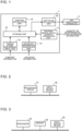
- Fig. 1 is a block diagram illustrating an example of the air-conditioning controller according to the present Embodiment 1.
- the air-conditioning controller 1 includes an environmental-state-quantity acquisition unit 11, an occupant-information acquisition unit 12, a temperature-preference input unit 13, a storage unit 14, a comfort calculation unit 15, and a set-value calculation unit 16.
- the environmental-state-quantity acquisition unit 11 acquires a quantity of environmental state that indicates an environmentally-related state of an air-conditioning target space. For example, the environmental-state-quantity acquisition unit 11 acquires sensor information detected by various types of sensors installed in air-conditioning apparatus 2 and the air-conditioning target space, and calculates the quantity of environmental state based on the acquired sensor information. While the environmental-state-quantity acquisition unit 11 acquires, for example, a PMV value as the quantity of environmental state, the environmental-state-quantity acquisition unit 11 not only calculates the PMV value based on the acquired sensor information, but may also acquire the PMV value itself. Note that the PMV is a value that can statistically evaluate the degree of satisfaction with the heat environment.
- the PMV value is used as the quantity of environmental state
- the PMV value may be calculated by using common values for some of the six variables. This can reduce the number of sensors to be installed to acquire the quantity of environmental state.
- the occupant-information acquisition unit 12 acquires occupant information that specifies occupants present in the air-conditioning target space.
- the occupant-information acquisition unit 12 acquires the occupant information by using commonlyknown technologies such as personal authentication technologies, image recognition technologies, or position sensing technologies.
- the temperature-preference input unit 13 receives an input of comfort information that indicates a warm-cold sense of each of the plurality of occupants present in the air-conditioning target space from the occupants present in this air-conditioning target space.
- the comfort information is input by using a computer, a smartphone, a tablet, a dedicated terminal, or other device (not illustrated) connected to the air-conditioning controller 1 with wire or wirelessly.
- the temperature-preference input unit 13 may be provided integrally with the occupant-information acquisition unit 12.
- the storage unit 14 stores various kinds of information to be used in the air-conditioning controller 1.
- the storage unit 14 stores the occupant information acquired by the occupant-information acquisition unit 12, the comfort information input to the temperature-preference input unit 13, and the quantity of environmental state when the occupant information and the comfort information are acquired such that the occupant information, the comfort information, and the quantity of environmental state are associated with each other.
- the comfort calculation unit 15 calculates a comfort range for each of the occupants based on the quantity of environmental state based on the information stored in the storage unit 14.
- the comfort range refers to an area that can be acquired based on a plurality of actual measured quantities of environmental state, and that includes the quantities of environmental state that can be determined to be comfortable.
- the set-value calculation unit 16 calculates a set value to the air-conditioning apparatus 2 based on the comfort range for each of the occupants.
- the set value is used to determine operation of the air-conditioning apparatus 2 and is, for example, a PMV value or a set temperature.
- the storage unit 14, the comfort calculation unit 15, and the set-value calculation unit 16 may be integrally provided as a single unit.
- Fig. 2 is a hardware configuration diagram illustrating an example of the configuration of the air-conditioning controller in Fig. 1 .
- the air-conditioning controller 1 in Fig. 1 is made up of a processing circuit 31 and an input-output device 32 as illustrated in Fig. 2 .
- the respective functions of the environmental-state-quantity acquisition unit 11, the occupant-information acquisition unit 12, the storage unit 14, the comfort calculation unit 15, and the set-value calculation unit 16 are implemented by the processing circuit 31.
- the temperature-preference input unit 13 in Fig. 1 corresponds to the input-output device 32 in Fig. 2 .
- the processing circuit 31 is equivalent to, for example, a single circuit, a combined circuit, a programmed processor, a parallel-programmed processor, an application specific integrated circuit (ASIC), a field-programmable gate array (FPGA), or a combination thereof.
- the functions of the environmental-state-quantity acquisition unit 11, the occupant-information acquisition unit 12, the storage unit 14, the comfort calculation unit 15, and the set-value calculation unit 16 may be implemented individually by processing circuits 31, or the functions of the respective units may be implemented collectively by a single processing circuit 31.
- Fig. 3 is a hardware configuration diagram illustrating another example of the configuration of the air-conditioning controller in Fig. 1 .
- the air-conditioning controller 1 in Fig. 1 is made up of a processor 33, a memory 34, and an input-output device 35 as illustrated in Fig. 3 .
- the respective functions of the environmental-state-quantity acquisition unit 11, the occupant-information acquisition unit 12, the storage unit 14, the comfort calculation unit 15, and the set-value calculation unit 16 are implemented by the processor 33 and the memory 34.
- the temperature-preference input unit 13 in Fig. 1 corresponds to the input-output device 35 in Fig. 3 .
- the functions of the environmental-state-quantity acquisition unit 11, the occupant-information acquisition unit 12, the storage unit 14, the comfort calculation unit 15, and the set-value calculation unit 16 are implemented by software, firmware, or a combination of the software and the firmware.
- the software and the firmware are described as programs and stored in the memory 34.
- the processor 33 reads and executes the programs stored in the memory 34, thereby to implement the functions of the respective units.
- nonvolatile or volatile semiconductor memories and other memories are used.
- the semiconductor memories include a random access memory (RAM), a read only memory (ROM), a flash memory, an erasable and programmable ROM (EPROM), and an electrically erasable and programmable ROM (EEPROM).
- RAM random access memory
- ROM read only memory
- EPROM erasable and programmable ROM
- EEPROM electrically erasable and programmable ROM
- a removable storage medium may be used as the memory 34. Examples of the removable storage medium include a magnetic disc, a flexible disc, an optical disc, a compact disc (CD), a mini disc (MD), and a digital versatile disc (DVD).
- the air-conditioning controller 1 according to the present Embodiment 1 performs the set-value determination processing for controlling the air-conditioning apparatus 2 to maximize the degree of satisfaction of each of a plurality of occupants present in an air-conditioning target space with the heat environment.
- the set-value determination processing is described below.
- a set value to the air-conditioning apparatus 2 is calculated such that a maximum in number of occupants of the plurality of occupants are satisfied with the heat environment of the air-conditioning target space.
- the PMV value is defined as a quantity of environmental state.
- a comfort range for each of the plurality of occupants present in the air-conditioning target space is determined.
- the comfort range is determined based on the comfort information that indicates a warm-cold sense input by each of the occupants, and based on the PMV value that is the quantity of environmental state in the air-conditioning target space at the point in time when the comfort information is input.
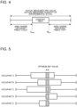
- Fig. 4 is an explanatory schematic diagram describing how to determine the comfort range.
- Fig. 4 illustrates an example of the relationship between the comfort information input by any of the occupants, and the PMV value (the quantity of environmental state) that is actually measured.
- the comfort information is input by categorizing the occupant's sense to the heat environment of the air-conditioning target space into levels such as “hot,” “slightly warm,” “neutral,” “slightly cool,” and “cold.”
- the comfort information may be input using numerical values, for example, “-3 (cold) to 0 (neutral) to 3 (hot).”
- the comfort range refers to an area where an occupant feels that the heat environment of the air-conditioning target space is in a "neutral” and proper state for the occupant.
- the comfort range is determined based on the plurality of inputs of the comfort information. Specifically, from the plurality of inputs of the comfort information on the same occupant, a PMV value H low and a PMV value C high are extracted.
- the PMV value H low is the smallest of the PMV values when this occupant feels hot.
- the PMV value C high is the largest of the PMV values when this occupant feels cold. As illustrated in Fig.
- the range of the PMV value between the upper limit and the lower limit is determined as a comfort range for this occupant.
- an optimum set value is determined as a set value optimum for the air-conditioning apparatus 2 based on the respective comfort ranges for the plurality of occupants.
- Fig. 5 is an explanatory schematic diagram describing how to determine the optimum set value.
- Fig. 5 illustrates respective comfort ranges for occupants A to E present in the air-conditioning target space.
- the optimum set value is set such that a maximum in number of occupants of the plurality of occupants are satisfied with the heating energy state of the air-conditioning target space.
- a set PMV value PMV_set is set to the comfort range for each of the plurality of occupants to calculate the number of occupants N of the plurality of occupants for which the set PMV value PMV_set falls within their comfort range.
- the set PMV value PMV_set is varied within the range of settable PMV value (for example, between -3 and 3) to search for a set PMV value PMV_set that maximizes the number of occupants N for which the set PMV value PMV_set falls within their comfort range.
- the set PMV value PMV_set that maximizes the number of occupants N for which the set PMV value PMV_set falls within their comfort range is searched out in this manner and thus determined as an optimum set value to the air-conditioning apparatus 2 as illustrated in Fig. 5 .
- the optimum set value to the air-conditioning apparatus 2 is determined such that a maximum in number of occupants N of the plurality of occupants are satisfied with the heating energy state of the air-conditioning target space. This can maximize the degree of satisfaction of the occupants present in the air-conditioning target space with the heat environment.
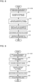
- Fig. 6 is a flowchart illustrating an example of a flow of the set-value determination processing performed by the air-conditioning controller 1 according to the present Embodiment 1.
- the environmental-state-quantity acquisition unit 11 acquires a quantity of environmental state in the air-conditioning target space.
- the environmental-state-quantity acquisition unit 11 acquires this quantity of environmental state regularly.
- the temperature-preference input unit 13 acquires comfort information input by the occupants.
- a terminal used for inputting the comfort information to the temperature-preference input unit 13 may be shared between the plurality of occupants, or each of the plurality of occupants may use their own dedicated terminal.
- the occupants may input the comfort information at a predetermined fixed time or at predetermined fixed intervals, or may input the comfort information as needed when the occupants feel dissatisfied with the heat environment.
- step S3 the occupant-information acquisition unit 12 acquires occupant information on the occupants present in the air-conditioning target space.
- the occupant-information acquisition unit 12 specifies the occupants who have input the comfort information through various kinds of authentication technologies.
- the occupant-information acquisition unit 12 may identify the individual terminal to specify the occupant.
- the temperature-preference input unit 13 provides the input comfort information to the storage unit 14.
- the occupant-information acquisition unit 12 provides the acquired occupant information to the storage unit 14.
- the environmental-state-quantity acquisition unit 11 provides the storage unit 14 with the quantity of environmental state at the point in time when the temperature-preference input unit 13 acquires the comfort information.
- the storage unit 14 stores the received comfort information, occupant information, and quantity of environmental state such that all the received information is associated with each other.
- step S5 the comfort calculation unit 15 extracts the minimum value H low from the PMV values (the quantity of environmental state) when the occupant feels hot, and extracts the maximum value C high from the PMV values (the quantity of environmental state) when the occupant feels cold.
- step S6 based on the minimum value H low when the occupant feels hot and the maximum value C high when the occupant feels cold, which have been extracted in step S5, the comfort calculation unit 15 sets the range of the quantity of environmental state between the maximum value C high and the minimum value H low as a comfort range.
- the comfort calculation unit 15 provides the set comfort range to the storage unit 14 to be stored therein. Then, the processing in steps S5 and S6 is performed the number of times equal to the number of occupants present in the air-conditioning target space.
- step S7 the set-value calculation unit 16 reads information on the comfort ranges for all the occupants present in the air-conditioning target space, stored in the storage unit 14, and sets a set environmental-state quantity PMV_set appropriate to each of these comfort ranges.
- step S8 the set-value calculation unit 16 calculates the number of occupants N of the plurality of occupants for which the set set environmental-state quantity PMV_set falls within their comfort range.
- step S9 the set-value calculation unit 16 varies the set environmental-state quantity PMV_set within the range of settable environmental-state quantity (in this example, -3 ⁇ PMV value ⁇ 3).
- the set-value calculation unit 16 searches for a set environmental-state quantity PMV_set that maximizes the number of occupants N of the plurality of occupants for which the set environmental-state quantity PMV_set falls within their comfort range.
- step S10 the set-value calculation unit 16 determines the set environmental-state quantity PMV_set that maximizes the number of occupants N described above as an optimum set value and transmits the optimum set value to the air-conditioning apparatus 2.
- the air-conditioning controller 1 calculates comfort ranges based on the occupant information on occupants present in the air-conditioning target space, the comfort information, and the quantity of environmental state. Then, the air-conditioning controller 1 calculates a set value to the air-conditioning apparatus based on the calculated comfort ranges in such a manner that a maximum in number of occupants of the plurality of occupants are satisfied with the state of the air-conditioning target space. With this operation, the quantity of environmental state in the air-conditioning target space is set at a value that falls within the comfort ranges for as many occupants of the plurality of occupants present in the air-conditioning target space as possible. This can maximize the degree of satisfaction of the occupants with the heat environment of the air-conditioning target space.
- an example case is considered where three occupants are present in the air-conditioning target space, and their respective optimum ranges of the PMV value as a quantity of environmental state are "-0.5 to -0.1,” “-0.2 to 0.4,” and "-0.2 to 0.4.”
- a simple mean value of the median in the comfort range "0" is a set value to the air-conditioning apparatus 2. Therefore, the number of occupants, for which this set value "0" falls within their comfort range, is two.
- the optimum set value is set anywhere between "-0.2 and -0.1.” Therefore, the number of occupants, for which this set value falls within their comfort range, is three. That is, the air-conditioning controller 1 according to the present Embodiment 1 can control the air-conditioning apparatus 2 in such a manner as to satisfy the comfort of all the three occupants present in the air-conditioning target space.
- the air-conditioning controller 1 according to the present Embodiment 2 is different from Embodiment 1 in that when there is an occupant who has a low degree of satisfaction with the heat environment of the air-conditioning target space, the air-conditioning controller 1 according to the present Embodiment 2 encourages this occupant to move to another zone.
- the components common to Embodiment 1 are denoted by the same reference signs, and detailed descriptions thereof are omitted.
- the air-conditioning controller 1 encourages the occupant to move from the current zone to another zone where the occupant's degree of satisfaction is further improved.
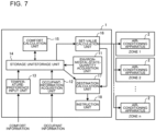
- Fig. 7 is a block diagram illustrating an example of the air-conditioning controller according to the present Embodiment 2.
- the air-conditioning controller 1 includes the environmental-state-quantity acquisition unit 11, the occupant-information acquisition unit 12, the temperature-preference input unit 13, the storage unit 14, the comfort calculation unit 15, the set-value calculation unit 16, a destination calculation unit 17, and an instruction unit 18.
- the set-value calculation unit 16 sets an optimum set value, so that the destination calculation unit 17 specifies the occupant for which the optimum set value does not fall within his/her own comfort range.
- the destination calculation unit 17 calculates a destination for the specified occupant. Note that in the descriptions below, the wording "the occupant for which the optimum set value does not fall within his/her own comfort range" is expressed as "the occupant having a low degree of satisfaction with the heat environment.”
- the instruction unit 18 provides an instruction regarding a destination zone for the occupant upon the determination performed by the destination calculation unit 17.
- a display or voice output unit of a computer, a smartphone, a tablet, a dedicated terminal or other device which are used for inputting the comfort information to the temperature-preference input unit 13 by an occupant is used.
- the air-conditioning controller 1 according to the present Embodiment 2 performs the destination determination processing for determining a more appropriate zone for this occupant and encourages this occupant to move from the current zone to another zone.
- the destination determination processing is described below.
- the air-conditioning controller 1 searches for another zone where an optimum set value falls within the comfort range for an occupant having a low degree of satisfaction with the heat environment in the current zone.
- the PMV value is defined as a quantity of environmental state.
- Fig. 8 is a flowchart illustrating an example of a flow of the destination determination processing performed by the air-conditioning controller according to the present Embodiment 2. Prior to the destination determination processing, the set-value determination processing including steps S1 to S10 described in Embodiment 1 is initially performed.
- step S11 the destination calculation unit 17 acquires an optimum set value to each zone from the set-value calculation unit 16.
- step S12 the destination calculation unit 17 reads and acquires information on the comfort ranges for the occupants in each zone, which is stored in the storage unit 14.
- step S13 the destination calculation unit 17 compares the comfort ranges for the occupants with the optimum set value to each zone, and specifies any of the occupants who have a low degree of satisfaction with the current heat environment. Specifically, when the optimum set value does not fall within the comfort range for the occupant, the destination calculation unit 17 specifies this occupant as having a low degree of satisfaction with the heat environment.
- step S14 the destination calculation unit 17 searches for a zone where the optimum set value falls within the comfort range for this occupant.
- the destination calculation unit 17 determines the zone having been searched out as a destination zone.
- step S15 the instruction unit 18 provides an instruction regarding the destination zone determined by the destination calculation unit 17 to this occupant.
- the destination calculation unit 17 determines a zone where there is a smallest difference between the optimum set value and an upper limit value or a lower limit value of the comfort range for this occupant as a destination zone.
- Fig. 9 is a flowchart illustrating an example of a flow of the destination determination processing when an additional occupant joins in an air-conditioning target space.
- the set-value determination processing including steps S1 to S10 described in Embodiment 1 is initially performed.
- step S21 the occupant-information acquisition unit 12 acquires occupant information on an occupant who has additionally joined in the air-conditioning target space.
- the destination calculation unit 17 specifies the occupant who has additionally joined based on the acquired occupant information.
- step S22 based on the occupant information on the specified occupant, the destination calculation unit 17 acquires information on the comfort range for this occupant stored in the storage unit 14. In step S23, the destination calculation unit 17 acquires an optimum set value to each zone from the set-value calculation unit 16.
- step S24 the destination calculation unit 17 searches for a zone where the optimum set value falls within the comfort range for this occupant.
- the destination calculation unit 17 determines the zone having been searched out as a destination zone.
- step S25 the instruction unit 18 provides an instruction regarding the destination zone determined by the destination calculation unit 17 to this occupant.
- a destination to which the occupant moves from the zone where the occupant is present is determined based on the set value to each of the zones.
- the air-conditioning controller 1 can encourage the occupant who has a low degree of satisfaction with the heat environment in the current zone to move to another zone where the degree of satisfaction is improved, so that the occupant can have improved comfort.
- the present Embodiments 1 and 2 have been described above, the present disclosure is not limited to Embodiments 1 and 2 described above. Various modifications and applications can be made without departing from the scope of the present disclosure.
- the quantity of environmental state is not limited thereto.
- a temperature, a humidity, an air velocity, a radiant temperature, or other factors in the air-conditioning target space is also applicable. Note that since the clothing insulation and the metabolic rate of an occupant also affect the occupant's warm-cold sense, these factors can thus be included in the quantity of environmental state in the present Embodiments 1 and 2. Further, a quantity calculated by using these quantities of environmental state is included in the quantity of environmental state.
- the air-conditioning controller 1 has been described as being configured separately from the air-conditioning apparatus 2.
- the air-conditioning controller 1 is not limited to this example.
- the air-conditioning controller 1 may function as a part of a controller provided in the air-conditioning apparatus 2.
- the functions of the air-conditioning controller 1 may be installed in any one of the air-conditioning apparatuses 2 to control the other air-conditioning apparatuses 2.
- 1 air-conditioning controller
- 2 air-conditioning apparatus
- 11 environment-state-quantity acquisition unit
- 12 occupant-information acquisition unit
- 13 temperature-preference input unit
- 14 storage unit
- 15 comfort calculation unit
- 16 set-value calculation unit
- 17 destination calculation unit
- 18 instruction unit
- 32, 35 input-output device
Landscapes
- Engineering & Computer Science (AREA)
- Signal Processing (AREA)
- Physics & Mathematics (AREA)
- Fuzzy Systems (AREA)
- Mathematical Physics (AREA)
- Chemical & Material Sciences (AREA)
- Combustion & Propulsion (AREA)
- Mechanical Engineering (AREA)
- General Engineering & Computer Science (AREA)
- Air Conditioning Control Device (AREA)
Abstract
Description
- The present disclosure relates to an air-conditioning controller and an air-conditioning apparatus that condition a heat environment of a space where a plurality of occupants are present.
- Conventionally, an air-conditioning device is provided in a building, an office, or other space to condition a heat environment of a single zone where a plurality of occupants are present. In a case where a plurality of occupants with different temperature preferences are under a single heat environment, it is necessary for the air-conditioning device to determine a set value that minimizes the degree of dissatisfaction of the occupants. To minimize the degree of dissatisfaction of these occupants, various methods for the air-conditioning device to determine an optimum set value have been proposed.
- For example,
Patent Literature 1 discloses an air-conditioning system configured to calculate a predicted mean vote (PMV) that can statistically evaluate the degree of satisfaction with respect to a heat environment, and to control an air-conditioning device such that the PMV falls within a range that is set in advance. This air-conditioning system can statistically maximize the degree of satisfaction with the heat environment by setting the PMV of the air-conditioning device to 0. - In addition,
Patent Literatures 2 and 3 disclose a method to evaluate the comfort to the heat environment by acquiring warm-cold sense vote information from occupants. In the method disclosed inPatent Literatures 2 and 3, the degree of satisfaction of the occupants with the heat environment is evaluated based on a mean value calculated based on the warm-cold sense voted from the occupants, or based on a model of satisfaction degree. -
- Patent Literature 1:
Japanese Unexamined Patent Application Publication No. 2020-134124 - Patent Literature 2:
Japanese Unexamined Patent Application Publication No. 2016-31220 - Patent Literature 3:
Japanese Unexamined Patent Application Publication No. 2019-100657 - The PMV is calculated using six variables including temperature, humidity, radiant temperature, air velocity, clothing insulation, and metabolic rate. The air-conditioning system disclosed in
Patent Literature 1 uses many measurement devices to measure these six variables to accurately calculate the PMV, and thus needs to locate these measurement devices in an air-conditioning target space. This results in problems that the air-conditioning system becomes complicated and its cost increases. - The method disclosed in
Patent Literatures 2 and 3 uses the mean value among a plurality of occupants, or uses the model of satisfaction degree. This also results in a problem that this mean value or model does not always match a set value at which a maximum number of occupants of the plurality of occupants feel comfortable in the air-conditioning target space. - The present disclosure has been made in view of the above problems caused by the conventional technique, and it is an object of the present disclosure to provide an air-conditioning controller and an air-conditioning apparatus that can maximize a degree of satisfaction of a plurality of occupants present in an air-conditioning target space with a heat environment without complicating a system.
- An air-conditioning controller according to one embodiment of the present disclosure is an air-conditioning controller configured to control an air-conditioning apparatus, and including: an environmental-state-quantity acquisition unit configured to acquire a quantity of environmental state that indicates a state of an air-conditioning target space; an occupant-information acquisition unit configured to acquire occupant information that specifies a plurality of occupants present in the air-conditioning target space; a temperature-preference input unit configured to acquire comfort information that indicates a warm-cold sense of each of the plurality of occupants to the air-conditioning target space; a storage unit configured to store the quantity of environmental state at a point in time when the comfort information is acquired, the occupant information, and the comfort information such that the quantity of environmental state at the point in time, the occupant information, and the comfort information are associated with each other; a comfort calculation unit configured to calculate a comfort range for each of the plurality of occupants based on the quantity of environmental state at the point in time, the occupant information, and the comfort information that are associated with each other and stored in the storage unit; and a set-value calculation unit configured to calculate a set value to the air-conditioning apparatus based on the calculated comfort range such that a maximum in number of occupants of the plurality of occupants are satisfied with the state of the air-conditioning target space.
- An air-conditioning apparatus according to another embodiment of the present disclosure includes the air-conditioning controller described above.
- According to the embodiments of the present disclosure, a set value to the air-conditioning apparatus is determined based on the comfort ranges for a plurality of occupants present in the air-conditioning target space such that a maximum in number of occupants of the plurality of occupants are satisfied with the state of the air-conditioning target space. This can maximize the degree of satisfaction of the plurality of occupants present in the air-conditioning target space with the heat environment.
-
- [
Fig. 1] Fig. 1 is a block diagram illustrating an example of an air-conditioning controller according toEmbodiment 1. - [
Fig. 2] Fig. 2 is a hardware configuration diagram illustrating an example of the configuration of the air-conditioning controller inFig. 1 . - [
Fig. 3] Fig. 3 is a hardware configuration diagram illustrating another example of the configuration of the air-conditioning controller inFig. 1 . - [
Fig. 4] Fig. 4 is an explanatory schematic diagram describing how to determine a comfort range. - [
Fig. 5] Fig. 5 is an explanatory schematic diagram describing how to determine an optimum set value. - [
Fig. 6] Fig. 6 is a flowchart illustrating an example of a flow of the set-value determination processing performed by an air-conditioning controller 1 according to thepresent Embodiment 1. - [
Fig. 7] Fig. 7 is a block diagram illustrating an example of the air-conditioning controller according toEmbodiment 2. - [
Fig. 8] Fig. 8 is a flowchart illustrating an example of a flow of the destination determination processing performed by the air-conditioning controller according toEmbodiment 2. - [
Fig. 9] Fig. 9 is a flowchart illustrating an example of a flow of the destination determination processing when an additional occupant joins in an air-conditioning target space. - Hereinafter, an embodiment of the present disclosure will be described based on the drawings. The present disclosure is not limited to the embodiment described below, and can be variously modified without departing from the scope of the present disclosure. In addition, the present disclosure includes all combinations of configurations that can be combined among the configurations shown in the embodiments described below. In the drawings below, the same reference signs denote the same or equivalent components, which are common throughout the entire specification.
- An air-conditioning controller according to the
present Embodiment 1 is described below. In a case where an air-conditioning target space is divided into a plurality of zones, and where one or a plurality of air-conditioning apparatuses are located to condition air in each of the divided zones, the air-conditioning controller is configured to control each of the air-conditioning apparatuses. In thepresent Embodiment 1, an example case is described where the air-conditioning controller controls an air-conditioning apparatus that conditions air in any of the plurality of zones. -
Fig. 1 is a block diagram illustrating an example of the air-conditioning controller according to thepresent Embodiment 1. As illustrated inFig. 1 , the air-conditioning controller 1 includes an environmental-state-quantity acquisition unit 11, an occupant-information acquisition unit 12, a temperature-preference input unit 13, astorage unit 14, acomfort calculation unit 15, and a set-value calculation unit 16. - The environmental-state-
quantity acquisition unit 11 acquires a quantity of environmental state that indicates an environmentally-related state of an air-conditioning target space. For example, the environmental-state-quantity acquisition unit 11 acquires sensor information detected by various types of sensors installed in air-conditioning apparatus 2 and the air-conditioning target space, and calculates the quantity of environmental state based on the acquired sensor information. While the environmental-state-quantity acquisition unit 11 acquires, for example, a PMV value as the quantity of environmental state, the environmental-state-quantity acquisition unit 11 not only calculates the PMV value based on the acquired sensor information, but may also acquire the PMV value itself. Note that the PMV is a value that can statistically evaluate the degree of satisfaction with the heat environment. - Note that in a case where the PMV value is used as the quantity of environmental state, when six variables are acquired to calculate the PMV value, it is not always necessary to accurately measure all the six variables. For example, the PMV value may be calculated by using common values for some of the six variables. This can reduce the number of sensors to be installed to acquire the quantity of environmental state.
- The occupant-
information acquisition unit 12 acquires occupant information that specifies occupants present in the air-conditioning target space. The occupant-information acquisition unit 12 acquires the occupant information by using commonlyknown technologies such as personal authentication technologies, image recognition technologies, or position sensing technologies. - The temperature-
preference input unit 13 receives an input of comfort information that indicates a warm-cold sense of each of the plurality of occupants present in the air-conditioning target space from the occupants present in this air-conditioning target space. For example, the comfort information is input by using a computer, a smartphone, a tablet, a dedicated terminal, or other device (not illustrated) connected to the air-conditioning controller 1 with wire or wirelessly. Note that the temperature-preference input unit 13 may be provided integrally with the occupant-information acquisition unit 12. - The
storage unit 14 stores various kinds of information to be used in the air-conditioning controller 1. For example, in thepresent Embodiment 1, thestorage unit 14 stores the occupant information acquired by the occupant-information acquisition unit 12, the comfort information input to the temperature-preference input unit 13, and the quantity of environmental state when the occupant information and the comfort information are acquired such that the occupant information, the comfort information, and the quantity of environmental state are associated with each other. - The
comfort calculation unit 15 calculates a comfort range for each of the occupants based on the quantity of environmental state based on the information stored in thestorage unit 14. The comfort range refers to an area that can be acquired based on a plurality of actual measured quantities of environmental state, and that includes the quantities of environmental state that can be determined to be comfortable. - The set-
value calculation unit 16 calculates a set value to the air-conditioning apparatus 2 based on the comfort range for each of the occupants. The set value is used to determine operation of the air-conditioning apparatus 2 and is, for example, a PMV value or a set temperature. Note that thestorage unit 14, thecomfort calculation unit 15, and the set-value calculation unit 16 may be integrally provided as a single unit. -
Fig. 2 is a hardware configuration diagram illustrating an example of the configuration of the air-conditioning controller inFig. 1 . In a case where various functions of the air-conditioning controller 1 are implemented by hardware, the air-conditioning controller 1 inFig. 1 is made up of aprocessing circuit 31 and an input-output device 32 as illustrated inFig. 2 . The respective functions of the environmental-state-quantity acquisition unit 11, the occupant-information acquisition unit 12, thestorage unit 14, thecomfort calculation unit 15, and the set-value calculation unit 16 are implemented by theprocessing circuit 31. The temperature-preference input unit 13 inFig. 1 corresponds to the input-output device 32 inFig. 2 . - In a case where the respective functions are implemented by hardware, the
processing circuit 31 is equivalent to, for example, a single circuit, a combined circuit, a programmed processor, a parallel-programmed processor, an application specific integrated circuit (ASIC), a field-programmable gate array (FPGA), or a combination thereof. The functions of the environmental-state-quantity acquisition unit 11, the occupant-information acquisition unit 12, thestorage unit 14, thecomfort calculation unit 15, and the set-value calculation unit 16 may be implemented individually by processingcircuits 31, or the functions of the respective units may be implemented collectively by asingle processing circuit 31. -
Fig. 3 is a hardware configuration diagram illustrating another example of the configuration of the air-conditioning controller inFig. 1 . In a case where various functions of the air-conditioning controller 1 are implemented by software, the air-conditioning controller 1 inFig. 1 is made up of aprocessor 33, amemory 34, and an input-output device 35 as illustrated inFig. 3 . The respective functions of the environmental-state-quantity acquisition unit 11, the occupant-information acquisition unit 12, thestorage unit 14, thecomfort calculation unit 15, and the set-value calculation unit 16 are implemented by theprocessor 33 and thememory 34. The temperature-preference input unit 13 inFig. 1 corresponds to the input-output device 35 inFig. 3 . - In a case where the respective functions are implemented by software, the functions of the environmental-state-
quantity acquisition unit 11, the occupant-information acquisition unit 12, thestorage unit 14, thecomfort calculation unit 15, and the set-value calculation unit 16 are implemented by software, firmware, or a combination of the software and the firmware. The software and the firmware are described as programs and stored in thememory 34. Theprocessor 33 reads and executes the programs stored in thememory 34, thereby to implement the functions of the respective units. - As the
memory 34, nonvolatile or volatile semiconductor memories and other memories are used. Examples of the semiconductor memories include a random access memory (RAM), a read only memory (ROM), a flash memory, an erasable and programmable ROM (EPROM), and an electrically erasable and programmable ROM (EEPROM). Alternatively, as thememory 34, a removable storage medium may be used. Examples of the removable storage medium include a magnetic disc, a flexible disc, an optical disc, a compact disc (CD), a mini disc (MD), and a digital versatile disc (DVD). - Next, operation of the air-
conditioning controller 1 according to thepresent Embodiment 1 is described. The air-conditioning controller 1 according to thepresent Embodiment 1 performs the set-value determination processing for controlling the air-conditioning apparatus 2 to maximize the degree of satisfaction of each of a plurality of occupants present in an air-conditioning target space with the heat environment. - The set-value determination processing is described below. In the set-value determination processing, a set value to the air-
conditioning apparatus 2 is calculated such that a maximum in number of occupants of the plurality of occupants are satisfied with the heat environment of the air-conditioning target space. Note that in the descriptions below, the PMV value is defined as a quantity of environmental state. - In the set-value determination processing, first a comfort range for each of the plurality of occupants present in the air-conditioning target space is determined. The comfort range is determined based on the comfort information that indicates a warm-cold sense input by each of the occupants, and based on the PMV value that is the quantity of environmental state in the air-conditioning target space at the point in time when the comfort information is input.
-
Fig. 4 is an explanatory schematic diagram describing how to determine the comfort range.Fig. 4 illustrates an example of the relationship between the comfort information input by any of the occupants, and the PMV value (the quantity of environmental state) that is actually measured. - The comfort information is input by categorizing the occupant's sense to the heat environment of the air-conditioning target space into levels such as "hot," "slightly warm," "neutral," "slightly cool," and "cold." The comfort information may be input using numerical values, for example, "-3 (cold) to 0 (neutral) to 3 (hot)." The comfort range refers to an area where an occupant feels that the heat environment of the air-conditioning target space is in a "neutral" and proper state for the occupant.
- When the same occupant inputs the comfort information multiple times, the comfort range is determined based on the plurality of inputs of the comfort information. Specifically, from the plurality of inputs of the comfort information on the same occupant, a PMV value Hlow and a PMV value Chigh are extracted. The PMV value Hlow is the smallest of the PMV values when this occupant feels hot. The PMV value Chigh is the largest of the PMV values when this occupant feels cold. As illustrated in
Fig. 4 , when "the PMV value Hlow that is the smallest of the PMV values when this occupant feels hot" is defined as an upper limit, while "the PMV value Chigh that is the largest of the PMV values when this occupant feels cold" is defined as a lower limit, then the range of the PMV value between the upper limit and the lower limit is determined as a comfort range for this occupant. - Next, in the set-value determination processing, as illustrated in
Fig. 4 , when the comfort range for each of the plurality of occupants present in the air-conditioning target space is determined, then an optimum set value is determined as a set value optimum for the air-conditioning apparatus 2 based on the respective comfort ranges for the plurality of occupants. -
Fig. 5 is an explanatory schematic diagram describing how to determine the optimum set value.Fig. 5 illustrates respective comfort ranges for occupants A to E present in the air-conditioning target space. The optimum set value is set such that a maximum in number of occupants of the plurality of occupants are satisfied with the heating energy state of the air-conditioning target space. - First, a set PMV value PMV_set is set to the comfort range for each of the plurality of occupants to calculate the number of occupants N of the plurality of occupants for which the set PMV value PMV_set falls within their comfort range. Next, the set PMV value PMV_set is varied within the range of settable PMV value (for example, between -3 and 3) to search for a set PMV value PMV_set that maximizes the number of occupants N for which the set PMV value PMV_set falls within their comfort range. The set PMV value PMV_set that maximizes the number of occupants N for which the set PMV value PMV_set falls within their comfort range is searched out in this manner and thus determined as an optimum set value to the air-
conditioning apparatus 2 as illustrated inFig. 5 . Note that in a case where there are a plurality of set PMV values PMV_set that maximize the number of occupants N described above, it is preferable to determine one of the set PMV values PMV_set, at which the air-conditioning apparatus 2 achieves the lowest power consumption, as an optimum set PMV value. - In the manner as described above, the optimum set value to the air-
conditioning apparatus 2 is determined such that a maximum in number of occupants N of the plurality of occupants are satisfied with the heating energy state of the air-conditioning target space. This can maximize the degree of satisfaction of the occupants present in the air-conditioning target space with the heat environment. -
Fig. 6 is a flowchart illustrating an example of a flow of the set-value determination processing performed by the air-conditioning controller 1 according to thepresent Embodiment 1. First, in step S1, the environmental-state-quantity acquisition unit 11 acquires a quantity of environmental state in the air-conditioning target space. The environmental-state-quantity acquisition unit 11 acquires this quantity of environmental state regularly. - In step S2, the temperature-
preference input unit 13 acquires comfort information input by the occupants. A terminal used for inputting the comfort information to the temperature-preference input unit 13 may be shared between the plurality of occupants, or each of the plurality of occupants may use their own dedicated terminal. The occupants may input the comfort information at a predetermined fixed time or at predetermined fixed intervals, or may input the comfort information as needed when the occupants feel dissatisfied with the heat environment. - In step S3, the occupant-
information acquisition unit 12 acquires occupant information on the occupants present in the air-conditioning target space. At this time, the occupant-information acquisition unit 12 specifies the occupants who have input the comfort information through various kinds of authentication technologies. In a case where each of the occupants uses their own individual terminal or the like to input the comfort information, the occupant-information acquisition unit 12 may identify the individual terminal to specify the occupant. - The temperature-
preference input unit 13 provides the input comfort information to thestorage unit 14. The occupant-information acquisition unit 12 provides the acquired occupant information to thestorage unit 14. Further, the environmental-state-quantity acquisition unit 11 provides thestorage unit 14 with the quantity of environmental state at the point in time when the temperature-preference input unit 13 acquires the comfort information. In step S4, thestorage unit 14 stores the received comfort information, occupant information, and quantity of environmental state such that all the received information is associated with each other. - In step S5, the
comfort calculation unit 15 extracts the minimum value Hlow from the PMV values (the quantity of environmental state) when the occupant feels hot, and extracts the maximum value Chigh from the PMV values (the quantity of environmental state) when the occupant feels cold. In step S6, based on the minimum value Hlow when the occupant feels hot and the maximum value Chigh when the occupant feels cold, which have been extracted in step S5, thecomfort calculation unit 15 sets the range of the quantity of environmental state between the maximum value Chigh and the minimum value Hlow as a comfort range. Thecomfort calculation unit 15 provides the set comfort range to thestorage unit 14 to be stored therein. Then, the processing in steps S5 and S6 is performed the number of times equal to the number of occupants present in the air-conditioning target space. - Next, in step S7, the set-
value calculation unit 16 reads information on the comfort ranges for all the occupants present in the air-conditioning target space, stored in thestorage unit 14, and sets a set environmental-state quantity PMV_set appropriate to each of these comfort ranges. In step S8, the set-value calculation unit 16 calculates the number of occupants N of the plurality of occupants for which the set set environmental-state quantity PMV_set falls within their comfort range. - In step S9, the set-
value calculation unit 16 varies the set environmental-state quantity PMV_set within the range of settable environmental-state quantity (in this example, -3 ≤ PMV value ≤ 3). The set-value calculation unit 16 searches for a set environmental-state quantity PMV_set that maximizes the number of occupants N of the plurality of occupants for which the set environmental-state quantity PMV_set falls within their comfort range. In step S10, the set-value calculation unit 16 determines the set environmental-state quantity PMV_set that maximizes the number of occupants N described above as an optimum set value and transmits the optimum set value to the air-conditioning apparatus 2. - As described above, the air-
conditioning controller 1 according to thepresent Embodiment 1 calculates comfort ranges based on the occupant information on occupants present in the air-conditioning target space, the comfort information, and the quantity of environmental state. Then, the air-conditioning controller 1 calculates a set value to the air-conditioning apparatus based on the calculated comfort ranges in such a manner that a maximum in number of occupants of the plurality of occupants are satisfied with the state of the air-conditioning target space. With this operation, the quantity of environmental state in the air-conditioning target space is set at a value that falls within the comfort ranges for as many occupants of the plurality of occupants present in the air-conditioning target space as possible. This can maximize the degree of satisfaction of the occupants with the heat environment of the air-conditioning target space. - Specifically, an example case is considered where three occupants are present in the air-conditioning target space, and their respective optimum ranges of the PMV value as a quantity of environmental state are "-0.5 to -0.1," "-0.2 to 0.4," and "-0.2 to 0.4." In this case, according to the conventional method, a simple mean value of the median in the comfort range "0" is a set value to the air-
conditioning apparatus 2. Therefore, the number of occupants, for which this set value "0" falls within their comfort range, is two. In contrast, in thepresent Embodiment 1, the optimum set value is set anywhere between "-0.2 and -0.1." Therefore, the number of occupants, for which this set value falls within their comfort range, is three. That is, the air-conditioning controller 1 according to thepresent Embodiment 1 can control the air-conditioning apparatus 2 in such a manner as to satisfy the comfort of all the three occupants present in the air-conditioning target space. - Next, the
present Embodiment 2 is described. The air-conditioning controller 1 according to thepresent Embodiment 2 is different fromEmbodiment 1 in that when there is an occupant who has a low degree of satisfaction with the heat environment of the air-conditioning target space, the air-conditioning controller 1 according to thepresent Embodiment 2 encourages this occupant to move to another zone. Note that in thepresent Embodiment 2, the components common toEmbodiment 1 are denoted by the same reference signs, and detailed descriptions thereof are omitted. - Based on the comfort ranges for a plurality of occupants present in a certain zone of the air-conditioning target space, when an optimum set value is set in such a manner as to maximize the number of occupants N of the plurality of occupants for which the optimum set value falls within their comfort range, then there may still be an occupant having a low degree of satisfaction with the heat environment of the air-conditioning target space in some cases. When such an occupant having a low degree of satisfaction continues to stay in the current zone, the degree of satisfaction is less likely to be improved. In view of that, in the
present Embodiment 2, to improve the degree of satisfaction with the heat environment of the air-conditioning target space, the air-conditioning controller 1 encourages the occupant to move from the current zone to another zone where the occupant's degree of satisfaction is further improved. -
Fig. 7 is a block diagram illustrating an example of the air-conditioning controller according to thepresent Embodiment 2. As illustrated inFig. 7 , the air-conditioning controller 1 includes the environmental-state-quantity acquisition unit 11, the occupant-information acquisition unit 12, the temperature-preference input unit 13, thestorage unit 14, thecomfort calculation unit 15, the set-value calculation unit 16, adestination calculation unit 17, and aninstruction unit 18. - With reference to the optimum set values for all the zones and the comfort ranges for the occupants in all the zones, the set-
value calculation unit 16 sets an optimum set value, so that thedestination calculation unit 17 specifies the occupant for which the optimum set value does not fall within his/her own comfort range. With reference to the comfort range for this specified occupant and the optimum set values for all the zones, thedestination calculation unit 17 calculates a destination for the specified occupant. Note that in the descriptions below, the wording "the occupant for which the optimum set value does not fall within his/her own comfort range" is expressed as "the occupant having a low degree of satisfaction with the heat environment." - The
instruction unit 18 provides an instruction regarding a destination zone for the occupant upon the determination performed by thedestination calculation unit 17. As theinstruction unit 18, for example, a display or voice output unit of a computer, a smartphone, a tablet, a dedicated terminal or other device which are used for inputting the comfort information to the temperature-preference input unit 13 by an occupant is used. - Next, operation of the air-
conditioning controller 1 according to thepresent Embodiment 2 is described. In a case where the optimum set value is set to each zone in the same manner as inEmbodiment 1 and there is an occupant having a low degree of satisfaction with the heat environment, the air-conditioning controller 1 according to thepresent Embodiment 2 performs the destination determination processing for determining a more appropriate zone for this occupant and encourages this occupant to move from the current zone to another zone. - The destination determination processing is described below. In the destination determination processing, the air-
conditioning controller 1 searches for another zone where an optimum set value falls within the comfort range for an occupant having a low degree of satisfaction with the heat environment in the current zone. Note that in the descriptions below, the PMV value is defined as a quantity of environmental state. -
Fig. 8 is a flowchart illustrating an example of a flow of the destination determination processing performed by the air-conditioning controller according to thepresent Embodiment 2. Prior to the destination determination processing, the set-value determination processing including steps S1 to S10 described inEmbodiment 1 is initially performed. - In step S11, the
destination calculation unit 17 acquires an optimum set value to each zone from the set-value calculation unit 16. In step S12, thedestination calculation unit 17 reads and acquires information on the comfort ranges for the occupants in each zone, which is stored in thestorage unit 14. In step S13, thedestination calculation unit 17 compares the comfort ranges for the occupants with the optimum set value to each zone, and specifies any of the occupants who have a low degree of satisfaction with the current heat environment. Specifically, when the optimum set value does not fall within the comfort range for the occupant, thedestination calculation unit 17 specifies this occupant as having a low degree of satisfaction with the heat environment. - In step S14, the
destination calculation unit 17 searches for a zone where the optimum set value falls within the comfort range for this occupant. Thedestination calculation unit 17 determines the zone having been searched out as a destination zone. In step S15, theinstruction unit 18 provides an instruction regarding the destination zone determined by thedestination calculation unit 17 to this occupant. - Note that it is conceivable that even though the
destination calculation unit 17 searches for the destination zone as described above, there still may not be the zone where the optimum set value falls within the comfort range for this occupant. In this case, thedestination calculation unit 17 determines a zone where there is a smallest difference between the optimum set value and an upper limit value or a lower limit value of the comfort range for this occupant as a destination zone. - In the
present Embodiment 2, even when an additional occupant joins in the air-conditioning target space, thedestination calculation unit 17 can still determine a destination zone for the additional occupant.Fig. 9 is a flowchart illustrating an example of a flow of the destination determination processing when an additional occupant joins in an air-conditioning target space. Prior to the destination determination processing, the set-value determination processing including steps S1 to S10 described inEmbodiment 1 is initially performed. - In step S21, the occupant-
information acquisition unit 12 acquires occupant information on an occupant who has additionally joined in the air-conditioning target space. Thedestination calculation unit 17 specifies the occupant who has additionally joined based on the acquired occupant information. - In step S22, based on the occupant information on the specified occupant, the
destination calculation unit 17 acquires information on the comfort range for this occupant stored in thestorage unit 14. In step S23, thedestination calculation unit 17 acquires an optimum set value to each zone from the set-value calculation unit 16. - In step S24, the
destination calculation unit 17 searches for a zone where the optimum set value falls within the comfort range for this occupant. Thedestination calculation unit 17 determines the zone having been searched out as a destination zone. - In step S25, the
instruction unit 18 provides an instruction regarding the destination zone determined by thedestination calculation unit 17 to this occupant. - As described above, in the air-
conditioning controller 1 according to thepresent Embodiment 2, a destination to which the occupant moves from the zone where the occupant is present is determined based on the set value to each of the zones. With this operation, the air-conditioning controller 1 can encourage the occupant who has a low degree of satisfaction with the heat environment in the current zone to move to another zone where the degree of satisfaction is improved, so that the occupant can have improved comfort. - While the present Embodiments 1 and 2 have been described above, the present disclosure is not limited to
Embodiments - In the present Embodiments 1 and 2, the air-
conditioning controller 1 has been described as being configured separately from the air-conditioning apparatus 2. However, the air-conditioning controller 1 is not limited to this example. For another example, the air-conditioning controller 1 may function as a part of a controller provided in the air-conditioning apparatus 2. In a case where a plurality of the air-conditioning apparatuses 2 are provided, the functions of the air-conditioning controller 1 may be installed in any one of the air-conditioning apparatuses 2 to control the other air-conditioning apparatuses 2. - 1: air-conditioning controller, 2: air-conditioning apparatus, 11: environment-state-quantity acquisition unit, 12: occupant-information acquisition unit, 13: temperature-preference input unit, 14: storage unit, 15: comfort calculation unit, 16: set-value calculation unit, 17: destination calculation unit, 18: instruction unit, 31: processing circuit, 32, 35: input-output device, 33: processor, 34: storage unit.
Claims (7)
- An air-conditioning controller configured to control an air-conditioning apparatus, the air-conditioning controller comprising:an environmental-state-quantity acquisition unit configured to acquire a quantity of environmental state that indicates a state of an air-conditioning target space;an occupant-information acquisition unit configured to acquire occupant information that specifies a plurality of occupants present in the air-conditioning target space;a temperature-preference input unit configured to acquire comfort information that indicates a warm-cold sense of each of the plurality of occupants to the air-conditioning target space;a storage unit configured to store the quantity of environmental state at a point in time when the comfort information is acquired, the occupant information, and the comfort information such that the quantity of environmental state at the point in time, the occupant information, and the comfort information are associated with each other;a comfort calculation unit configured to calculate a comfort range for each of the plurality of occupants based on the quantity of environmental state at the point in time, the occupant information, and the comfort information that are associated with each other and stored in the storage unit; anda set-value calculation unit configured to calculate a set value to the air-conditioning apparatus based on the calculated comfort range such that a maximum in number of occupants of the plurality of occupants are satisfied with the state of the air-conditioning target space.
- The air-conditioning controller of claim 1, wherein the comfort calculation unit is configured to
define, as the comfort range, a range of a quantity of environmental state between a maximum value of the quantity of environmental state when the occupant feels cold and a minimum value of the quantity of environmental state when the occupant feels hot. - The air-conditioning controller of claim 1 or 2, wherein the set-value calculation unit is configured to
set, as an optimum set value, the set value that causes a number of the comfort ranges for the plurality of occupants within which the set value falls to be maximized. - The air-conditioning controller of claim 3, wherein the set-value calculation unit is configured to,
when there are a plurality of the optimum set values, define one of the optimum set values, at which the air-conditioning apparatus achieves lowest power consumption, as the optimum set value. - The air-conditioning controller of any one of claims 1 to 4, wherein the air-conditioning target space is divided into a plurality of zones, and one or a plurality of the air-conditioning apparatuses are located to condition air in each of the divided zones, and
wherein the air-conditioning controller further comprises:a destination calculation unit configured to calculate a destination to which the occupant moves from the zone where the occupant is present based on the comfort information and the set value to each of the zones; andan instruction unit configured to instruct the occupant to move from the zone based on a calculation result from the destination calculation unit. - The air-conditioning controller of claim 5 as dependent on claim 3 or 4, wherein
the destination calculation unit is configured tospecify the occupant for which the optimum set value to the current zone does not fall within the comfort range as an occupant having a low degree of satisfaction with a heat environment of the current zone,search for a zone where the optimum set value falls within the comfort range for the specified occupant, anddetermine the zone that is searched out as a destination zone. - An air-conditioning apparatus comprising the air-conditioning controller of any one of claims 1 to 6.
Applications Claiming Priority (1)
| Application Number | Priority Date | Filing Date | Title |
|---|---|---|---|
| PCT/JP2021/024146 WO2022269903A1 (en) | 2021-06-25 | 2021-06-25 | Air-conditioning control device and air conditioner |
Publications (2)
| Publication Number | Publication Date |
|---|---|
| EP4361514A1 true EP4361514A1 (en) | 2024-05-01 |
| EP4361514A4 EP4361514A4 (en) | 2024-08-07 |
Family
ID=84544364
Family Applications (1)
| Application Number | Title | Priority Date | Filing Date |
|---|---|---|---|
| EP21947185.1A Withdrawn EP4361514A4 (en) | 2021-06-25 | 2021-06-25 | Air-conditioning control device and air conditioner |
Country Status (5)
| Country | Link |
|---|---|
| US (1) | US20240318854A1 (en) |
| EP (1) | EP4361514A4 (en) |
| JP (1) | JP7483139B2 (en) |
| CN (1) | CN117501054A (en) |
| WO (1) | WO2022269903A1 (en) |
Family Cites Families (13)
| Publication number | Priority date | Publication date | Assignee | Title |
|---|---|---|---|---|
| JP6071728B2 (en) * | 2013-04-25 | 2017-02-01 | 大成建設株式会社 | Comfort environment selection support device and comfort environment selection support method |
| EP3705937B1 (en) * | 2014-06-30 | 2023-03-15 | View, Inc. | Computer-implemented control methods and systems for networks of optically switchable windows during reduced power availability |
| JP2016031220A (en) | 2014-07-30 | 2016-03-07 | 株式会社東芝 | Air conditioning optimization device and air conditioning control system |
| EP3344924A1 (en) * | 2015-09-03 | 2018-07-11 | Robert Bosch GmbH | Methods for determining a target operation point, target operation point determination devices, and user input devices |
| WO2018163272A1 (en) | 2017-03-07 | 2018-09-13 | 三菱電機株式会社 | Air conditioning device, air conditioning system, and control method |
| JP6772961B2 (en) * | 2017-05-31 | 2020-10-21 | ダイキン工業株式会社 | Mobile control system |
| WO2019013014A1 (en) * | 2017-07-12 | 2019-01-17 | 三菱電機株式会社 | Comfort level display device |
| US10708077B2 (en) * | 2017-11-21 | 2020-07-07 | Abb Schweiz Ag | Technologies for optimally individualized building automation |
| JP6940387B2 (en) | 2017-12-06 | 2021-09-29 | アズビル株式会社 | Hot and cold feeling report information processing device and method |
| JP6955450B2 (en) | 2018-01-17 | 2021-10-27 | 日立グローバルライフソリューションズ株式会社 | Air conditioning control system and air conditioning control method |
| JP2020134124A (en) | 2019-02-12 | 2020-08-31 | 大成建設株式会社 | Air-conditioning system and control method for air-conditioning device |
| US11719458B2 (en) * | 2020-04-16 | 2023-08-08 | Robert Bosch Gmbh | HVAC control fine-grained occupancy pattern estimation |
| CN112927052A (en) * | 2021-03-30 | 2021-06-08 | 福建诺诚数字科技有限公司 | Merchant recommendation method and device based on multi-person collaborative decision and multi-departure place |
-
2021
- 2021-06-25 WO PCT/JP2021/024146 patent/WO2022269903A1/en not_active Ceased
- 2021-06-25 CN CN202180099553.5A patent/CN117501054A/en active Pending
- 2021-06-25 EP EP21947185.1A patent/EP4361514A4/en not_active Withdrawn
- 2021-06-25 JP JP2023529407A patent/JP7483139B2/en active Active
- 2021-06-25 US US18/556,471 patent/US20240318854A1/en active Pending
Also Published As
| Publication number | Publication date |
|---|---|
| CN117501054A (en) | 2024-02-02 |
| US20240318854A1 (en) | 2024-09-26 |
| JP7483139B2 (en) | 2024-05-14 |
| JPWO2022269903A1 (en) | 2022-12-29 |
| WO2022269903A1 (en) | 2022-12-29 |
| EP4361514A4 (en) | 2024-08-07 |
Similar Documents
| Publication | Publication Date | Title |
|---|---|---|
| US9477240B2 (en) | Centralized controller for intelligent control of thermostatically controlled devices | |
| EP3078919B1 (en) | Apparatus and method for controlling comfort temperature of air conditioning device or air conditioning system | |
| EP3284622B1 (en) | Air-conditioning control device | |
| US20160131383A1 (en) | Group dynamic environment control | |
| CN106123255B (en) | Air conditioner control method and air conditioner | |
| JP6173784B2 (en) | Air conditioning energy management system, method, and program | |
| US20160320081A1 (en) | Method and System for Personalization of Heating, Ventilation, and Air Conditioning Services | |
| EP3410027B1 (en) | Air conditioner system | |
| CN108759003B (en) | Air conditioner control method, air conditioner, and computer-readable storage medium | |
| CN110736249A (en) | Method and device for controlling running frequency of compressor, storage medium and processor | |
| JP6396542B2 (en) | Air conditioning control device, method, and program | |
| JP6568385B2 (en) | Air conditioning controller | |
| CN111964216B (en) | Method and device for air conditioner constant temperature control and air conditioner | |
| CN110529987B (en) | Biological characteristic air conditioner control system | |
| KR101504411B1 (en) | Method and system for automatically controlling building temperature through temperature control pattern | |
| CN112378055A (en) | Air conditioner control method and device, air conditioner indoor unit, air conditioner system and storage medium | |
| CN114771200A (en) | Temperature control method and system in cabin and electric automobile | |
| JPWO2019188375A1 (en) | Infrared sensor module, air conditioner, air conditioner control system | |
| KR20160123227A (en) | Air conditioning control device | |
| EP3039502B1 (en) | Method for temperature control | |
| EP4361514A1 (en) | Air-conditioning control device and air conditioner | |
| CN113623815A (en) | Air conditioner control method, system, air conditioner and storage medium | |
| JP7054782B2 (en) | Control information output system, device control system, device control method, and program | |
| JP2022094505A (en) | Air-conditioning system | |
| JP7126307B2 (en) | air conditioning control system |
Legal Events
| Date | Code | Title | Description |
|---|---|---|---|
| STAA | Information on the status of an ep patent application or granted ep patent |
Free format text: STATUS: THE INTERNATIONAL PUBLICATION HAS BEEN MADE |
|
| PUAI | Public reference made under article 153(3) epc to a published international application that has entered the european phase |
Free format text: ORIGINAL CODE: 0009012 |
|
| STAA | Information on the status of an ep patent application or granted ep patent |
Free format text: STATUS: REQUEST FOR EXAMINATION WAS MADE |
|
| 17P | Request for examination filed |
Effective date: 20231218 |
|
| AK | Designated contracting states |
Kind code of ref document: A1 Designated state(s): AL AT BE BG CH CY CZ DE DK EE ES FI FR GB GR HR HU IE IS IT LI LT LU LV MC MK MT NL NO PL PT RO RS SE SI SK SM TR |
|
| A4 | Supplementary search report drawn up and despatched |
Effective date: 20240705 |
|
| RIC1 | Information provided on ipc code assigned before grant |
Ipc: F24F 120/20 20180101ALI20240701BHEP Ipc: F24F 120/12 20180101ALI20240701BHEP Ipc: F24F 120/10 20180101ALI20240701BHEP Ipc: F24F 110/10 20180101ALI20240701BHEP Ipc: F24F 11/63 20180101AFI20240701BHEP |
|
| DAV | Request for validation of the european patent (deleted) | ||
| DAX | Request for extension of the european patent (deleted) | ||
| STAA | Information on the status of an ep patent application or granted ep patent |
Free format text: STATUS: THE APPLICATION HAS BEEN WITHDRAWN |
|
| 18W | Application withdrawn |
Effective date: 20241204 |