EP4361479A1 - Valve actuation mechanism, valve arrangement and pipe installation for lh2 applications as well as use thereof - Google Patents
Valve actuation mechanism, valve arrangement and pipe installation for lh2 applications as well as use thereof Download PDFInfo
- Publication number
- EP4361479A1 EP4361479A1 EP22204327.5A EP22204327A EP4361479A1 EP 4361479 A1 EP4361479 A1 EP 4361479A1 EP 22204327 A EP22204327 A EP 22204327A EP 4361479 A1 EP4361479 A1 EP 4361479A1
- Authority
- EP
- European Patent Office
- Prior art keywords
- valve
- shaft
- housing
- actuation mechanism
- area
- Prior art date
- Legal status (The legal status is an assumption and is not a legal conclusion. Google has not performed a legal analysis and makes no representation as to the accuracy of the status listed.)
- Pending
Links
- 238000009434 installation Methods 0.000 title claims description 16
- 239000012528 membrane Substances 0.000 claims abstract description 36
- 238000007789 sealing Methods 0.000 claims abstract description 19
- 239000001257 hydrogen Substances 0.000 claims description 25
- 229910052739 hydrogen Inorganic materials 0.000 claims description 25
- UFHFLCQGNIYNRP-UHFFFAOYSA-N Hydrogen Chemical compound [H][H] UFHFLCQGNIYNRP-UHFFFAOYSA-N 0.000 claims description 14
- 150000002431 hydrogen Chemical class 0.000 claims description 11
- 239000002775 capsule Substances 0.000 claims description 9
- 239000007788 liquid Substances 0.000 claims description 6
- 230000003068 static effect Effects 0.000 claims description 4
- 239000007789 gas Substances 0.000 description 7
- 230000005540 biological transmission Effects 0.000 description 2
- 239000000446 fuel Substances 0.000 description 2
- 230000008878 coupling Effects 0.000 description 1
- 238000010168 coupling process Methods 0.000 description 1
- 238000005859 coupling reaction Methods 0.000 description 1
- 230000001419 dependent effect Effects 0.000 description 1
- 230000005489 elastic deformation Effects 0.000 description 1
- 238000009413 insulation Methods 0.000 description 1
- 230000010354 integration Effects 0.000 description 1
- 238000012423 maintenance Methods 0.000 description 1
- 239000002184 metal Substances 0.000 description 1
- 150000003384 small molecules Chemical class 0.000 description 1
Images

Classifications
-
- F—MECHANICAL ENGINEERING; LIGHTING; HEATING; WEAPONS; BLASTING
- F17—STORING OR DISTRIBUTING GASES OR LIQUIDS
- F17C—VESSELS FOR CONTAINING OR STORING COMPRESSED, LIQUEFIED OR SOLIDIFIED GASES; FIXED-CAPACITY GAS-HOLDERS; FILLING VESSELS WITH, OR DISCHARGING FROM VESSELS, COMPRESSED, LIQUEFIED, OR SOLIDIFIED GASES
- F17C13/00—Details of vessels or of the filling or discharging of vessels
- F17C13/04—Arrangement or mounting of valves
-
- B—PERFORMING OPERATIONS; TRANSPORTING
- B64—AIRCRAFT; AVIATION; COSMONAUTICS
- B64D—EQUIPMENT FOR FITTING IN OR TO AIRCRAFT; FLIGHT SUITS; PARACHUTES; ARRANGEMENT OR MOUNTING OF POWER PLANTS OR PROPULSION TRANSMISSIONS IN AIRCRAFT
- B64D37/00—Arrangements in connection with fuel supply for power plant
- B64D37/005—Accessories not provided for in the groups B64D37/02 - B64D37/28
-
- E—FIXED CONSTRUCTIONS
- E04—BUILDING
- E04H—BUILDINGS OR LIKE STRUCTURES FOR PARTICULAR PURPOSES; SWIMMING OR SPLASH BATHS OR POOLS; MASTS; FENCING; TENTS OR CANOPIES, IN GENERAL
- E04H6/00—Buildings for parking cars, rolling-stock, aircraft, vessels or like vehicles, e.g. garages
- E04H6/44—Buildings for parking cars, rolling-stock, aircraft, vessels or like vehicles, e.g. garages for storing aircraft
-
- F—MECHANICAL ENGINEERING; LIGHTING; HEATING; WEAPONS; BLASTING
- F16—ENGINEERING ELEMENTS AND UNITS; GENERAL MEASURES FOR PRODUCING AND MAINTAINING EFFECTIVE FUNCTIONING OF MACHINES OR INSTALLATIONS; THERMAL INSULATION IN GENERAL
- F16H—GEARING
- F16H49/00—Other gearings
- F16H49/001—Wave gearings, e.g. harmonic drive transmissions
-
- F—MECHANICAL ENGINEERING; LIGHTING; HEATING; WEAPONS; BLASTING
- F16—ENGINEERING ELEMENTS AND UNITS; GENERAL MEASURES FOR PRODUCING AND MAINTAINING EFFECTIVE FUNCTIONING OF MACHINES OR INSTALLATIONS; THERMAL INSULATION IN GENERAL
- F16K—VALVES; TAPS; COCKS; ACTUATING-FLOATS; DEVICES FOR VENTING OR AERATING
- F16K1/00—Lift valves or globe valves, i.e. cut-off apparatus with closure members having at least a component of their opening and closing motion perpendicular to the closing faces
- F16K1/16—Lift valves or globe valves, i.e. cut-off apparatus with closure members having at least a component of their opening and closing motion perpendicular to the closing faces with pivoted closure-members
- F16K1/18—Lift valves or globe valves, i.e. cut-off apparatus with closure members having at least a component of their opening and closing motion perpendicular to the closing faces with pivoted closure-members with pivoted discs or flaps
- F16K1/22—Lift valves or globe valves, i.e. cut-off apparatus with closure members having at least a component of their opening and closing motion perpendicular to the closing faces with pivoted closure-members with pivoted discs or flaps with axis of rotation crossing the valve member, e.g. butterfly valves
- F16K1/226—Shaping or arrangements of the sealing
- F16K1/2268—Sealing means for the axis of rotation
-
- F—MECHANICAL ENGINEERING; LIGHTING; HEATING; WEAPONS; BLASTING
- F16—ENGINEERING ELEMENTS AND UNITS; GENERAL MEASURES FOR PRODUCING AND MAINTAINING EFFECTIVE FUNCTIONING OF MACHINES OR INSTALLATIONS; THERMAL INSULATION IN GENERAL
- F16K—VALVES; TAPS; COCKS; ACTUATING-FLOATS; DEVICES FOR VENTING OR AERATING
- F16K31/00—Actuating devices; Operating means; Releasing devices
- F16K31/44—Mechanical actuating means
- F16K31/52—Mechanical actuating means with crank, eccentric, or cam
- F16K31/524—Mechanical actuating means with crank, eccentric, or cam with a cam
-
- F—MECHANICAL ENGINEERING; LIGHTING; HEATING; WEAPONS; BLASTING
- F16—ENGINEERING ELEMENTS AND UNITS; GENERAL MEASURES FOR PRODUCING AND MAINTAINING EFFECTIVE FUNCTIONING OF MACHINES OR INSTALLATIONS; THERMAL INSULATION IN GENERAL
- F16K—VALVES; TAPS; COCKS; ACTUATING-FLOATS; DEVICES FOR VENTING OR AERATING
- F16K31/00—Actuating devices; Operating means; Releasing devices
- F16K31/44—Mechanical actuating means
- F16K31/53—Mechanical actuating means with toothed gearing
-
- F—MECHANICAL ENGINEERING; LIGHTING; HEATING; WEAPONS; BLASTING
- F16—ENGINEERING ELEMENTS AND UNITS; GENERAL MEASURES FOR PRODUCING AND MAINTAINING EFFECTIVE FUNCTIONING OF MACHINES OR INSTALLATIONS; THERMAL INSULATION IN GENERAL
- F16K—VALVES; TAPS; COCKS; ACTUATING-FLOATS; DEVICES FOR VENTING OR AERATING
- F16K31/00—Actuating devices; Operating means; Releasing devices
- F16K31/44—Mechanical actuating means
- F16K31/53—Mechanical actuating means with toothed gearing
- F16K31/535—Mechanical actuating means with toothed gearing for rotating valves
-
- F—MECHANICAL ENGINEERING; LIGHTING; HEATING; WEAPONS; BLASTING
- F16—ENGINEERING ELEMENTS AND UNITS; GENERAL MEASURES FOR PRODUCING AND MAINTAINING EFFECTIVE FUNCTIONING OF MACHINES OR INSTALLATIONS; THERMAL INSULATION IN GENERAL
- F16K—VALVES; TAPS; COCKS; ACTUATING-FLOATS; DEVICES FOR VENTING OR AERATING
- F16K31/00—Actuating devices; Operating means; Releasing devices
- F16K31/44—Mechanical actuating means
- F16K31/60—Handles
-
- F—MECHANICAL ENGINEERING; LIGHTING; HEATING; WEAPONS; BLASTING
- F16—ENGINEERING ELEMENTS AND UNITS; GENERAL MEASURES FOR PRODUCING AND MAINTAINING EFFECTIVE FUNCTIONING OF MACHINES OR INSTALLATIONS; THERMAL INSULATION IN GENERAL
- F16K—VALVES; TAPS; COCKS; ACTUATING-FLOATS; DEVICES FOR VENTING OR AERATING
- F16K5/00—Plug valves; Taps or cocks comprising only cut-off apparatus having at least one of the sealing faces shaped as a more or less complete surface of a solid of revolution, the opening and closing movement being predominantly rotary
- F16K5/06—Plug valves; Taps or cocks comprising only cut-off apparatus having at least one of the sealing faces shaped as a more or less complete surface of a solid of revolution, the opening and closing movement being predominantly rotary with plugs having spherical surfaces; Packings therefor
- F16K5/0663—Packings
- F16K5/0694—Spindle sealings
-
- B—PERFORMING OPERATIONS; TRANSPORTING
- B64—AIRCRAFT; AVIATION; COSMONAUTICS
- B64D—EQUIPMENT FOR FITTING IN OR TO AIRCRAFT; FLIGHT SUITS; PARACHUTES; ARRANGEMENT OR MOUNTING OF POWER PLANTS OR PROPULSION TRANSMISSIONS IN AIRCRAFT
- B64D37/00—Arrangements in connection with fuel supply for power plant
- B64D37/30—Fuel systems for specific fuels
-
- B—PERFORMING OPERATIONS; TRANSPORTING
- B64—AIRCRAFT; AVIATION; COSMONAUTICS
- B64F—GROUND OR AIRCRAFT-CARRIER-DECK INSTALLATIONS SPECIALLY ADAPTED FOR USE IN CONNECTION WITH AIRCRAFT; DESIGNING, MANUFACTURING, ASSEMBLING, CLEANING, MAINTAINING OR REPAIRING AIRCRAFT, NOT OTHERWISE PROVIDED FOR; HANDLING, TRANSPORTING, TESTING OR INSPECTING AIRCRAFT COMPONENTS, NOT OTHERWISE PROVIDED FOR
- B64F1/00—Ground or aircraft-carrier-deck installations
- B64F1/28—Liquid-handling installations specially adapted for fuelling stationary aircraft
-
- F—MECHANICAL ENGINEERING; LIGHTING; HEATING; WEAPONS; BLASTING
- F16—ENGINEERING ELEMENTS AND UNITS; GENERAL MEASURES FOR PRODUCING AND MAINTAINING EFFECTIVE FUNCTIONING OF MACHINES OR INSTALLATIONS; THERMAL INSULATION IN GENERAL
- F16H—GEARING
- F16H49/00—Other gearings
- F16H49/001—Wave gearings, e.g. harmonic drive transmissions
- F16H2049/003—Features of the flexsplines therefor
Definitions
- the invention relates to a valve actuation mechanism for actuating a valve for cryogenic applications and/or H2 applications. Further, the invention relates to a valve arrangement having such a valve actuating mechanism. Further, the invention relates to a cryogenic pipe installation for conducting liquid hydrogen, a vehicle, and an airport as possible uses of such valve arrangement.
- [1] to [3] relate to hydrogen installations in an aircraft.
- Preferred embodiments of the invention relate to parts of installations of hydrogen systems on an aircraft, vehicles or on ground.
- a hydrogen distribution system is needed on the aircraft.
- the hydrogen distribution system especially includes a hydrogen duct system with pipes, couplings, pipe branches, equipment and so on for distributing the hydrogen, which may be liquid hydrogen (LH2, especially cryogenic) or gaseous hydrogen (GH2).
- LH2 liquid hydrogen
- GH2 gaseous hydrogen
- hydrogen systems are also needed on airports and eventually on tank vehicles.
- valves are needed to control, enable or stop flow of hydrogen.
- An object of the invention is to improve a valve actuation mechanism for use with high anti-leakage requirements, especially in H2 applications, more particulary LH2 applications.
- the invention provides a valve actuation mechanism according to claim 1.
- a valve arrangement for H2 applications, especially LH2 applications, and advantageous uses thereof are subject-matter of the further independent claims.
- the invention provides a valve actuation mechanism for actuating a rotatable closing element of a valve for cryogenic applications and/or H2 applications, comprising:
- the input shaft is selected from the group consisting of a shaft of a manual lever, a driving shaft of a motorized actuator, a driving shaft of an electric actuator, a driving shaft of a pneumatic actuator, a shaft of a crank, a shaft of a crank lever, a shaft of a handwheel.
- the housing is a canisterized housing with vacuum.
- the housing defines the inner area as a first sealed chamber and further defines a second sealed chamber sealed by the sealing membrane from the first sealed chamber, wherein at least a portion of the input shaft connected to one of the wave generator and the outer gear wheel is arranged within the second sealed chamber.
- the housing has a connection means to be connected to a valve housing of a valve to be actuated.
- the housing has a bolted removable cap with static seal.
- the membrane seal comprises a pot shaped centre area with an annular wall wherein at least an annular portion of the annular wall comprises the external teeth of the flexible ring gear.
- the membrane seal comprises an annular intermediate area extending essentially radially with a wave shaped expansion portion, especially a bellow shaped portion.
- the membrane seal comprises an outer rim portion or flange portion fixedly connected to the housing.
- the invention provides a valve arrangement for LH2 applications, comprising a valve with a closing element which is movable between a closed position and an open position by a rotation movement and a valve actuation mechanism according to any of the aforementioned embodiments.
- the valve is a ball valve or butterfly valve.
- the valve arrangement comprises a vacuum capsule boundary, wherein the housing is welded to the capsule.
- the invention provides a cryogenic pipe installation for conducting liquid hydrogen, comprising a valve arrangement according to any of the aforementioned embodiments.
- the invention provides a vehicle, especially an aircraft with at least one hydrogen consumer or a LH2 tank vehicle, comprising a valve actuating mechanism, a valve arrangement, and/or a cryogenic pipe installation according to any of the aforementioned embodiments.
- the invention provides an airport comprising a cryogenic pipe installation with such valve actuation mechanism according to any of the aforementioned embodiments.
- Preferred embodiments can be used in the technical field of small molecule gas transportation to be controlled via valves subjected to very high leakage tightness requirements.
- Preferred embodiments relate to gas tight membrane seals for rotation transmission. Preferred embodiments relate to a gas tight rotational seal. Preferred embodiments relate to hydrogen control and distribution equipment.
- the invention especially lies on the technical field of hydrogen powered aircrafts and installations related therewith.
- One of the challenges connected therewith is the integration of hydrogen control and distribution equipment.
- Shut-off and distribution ball valves are the preferred choice over piston valves or poppet valves.
- a challenge experienced with use of ball valves is that they require a rotational seal. It is quite difficult to provide a rotational seal such that it is gas tight for liquid hydrogen use. Thus, any dynamic movements would increase leakage. Leaking of larger amounts of H2 should be avoided for different reasons. This phenomenon is not present in a membrane sealed piston poppet valve due to the translational operation of the closing elements thereof.
- Embodiments of the invention make use of a concept similar to a strain wave gearing (also called “harmonic drive”) as known from [4].
- a membrane transmits a torque moment to separate components involved in the mechanism.
- the flexible gear is formed by a part of a sealing membrane.
- the sealing membrane is stationary so that it can be tightly fixed within an housing, and it can securely seal an inner area of the housing from an outer area.
- the wave generator has a rotatable element such as an ellipsoid gear or any other excentric gear that is suitable to deform the flexible gear such that some of the outer teeth thereof engage some of the inner teeth of the outer wheel. Hence, rotational movement can be transmitted via gas tight stationary sealing.
- Either of the wave generator or the outer wheel could be used as input while the other thereof is used as output for actuating a valve.
- the rotatable element of the wave generator is used as input for the rotational movement
- the outer wheel is used as output that can be connected to a rotating closing element of a valve such as a ball valve.
- Ball valve shut-off valves have some advantages over piston valves for LH2 applications, particularly for the non-motorized ones.
- the challenge is that the actuation of the ball valve requires a shaft rotation which - as far as known - today cannot be designed leakage tight for very small molecular gases in a similar way as this is possible with a longitudinal actuation for a piston valve to be sealed by a membrane.
- Embodiments of the invention make use of the principle of harmonic drive gear boxes such as known from [4] for transmitting rotational movements for actuating valves. This is especially useful for ball valves but of course also for all other valves that can be actuated - directly or indirectly - by a rotational movement.
- harmonic drive gearboxes usually have a transmission ratio more than 1:25 so that one needs more than six turns to close a ball valve with a 90° movement. Therefore, manual operation elements that easily can be turned several times are preferred such as cranks, hand wheels or crank levers.
- automatic rotation drive actuators such as stepper motors, electric actuators, hydraulic motors or pneumatic motors could also be connected to the input shaft.
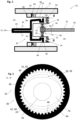
- Fig. 1 shows a valve actuation mechanism 10 for actuating a valve 12 for cryogenic applications and/or H2 applications.
- Fig. 2 shows a section through parts of the valve actuation mechanism 10 along line II - II of Fig. 1 .
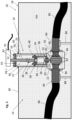
- Fig. 3 shows a valve arrangement 14 including a valve 12 and the valve actuation mechanism 10 for actuating the valve 12.
- the valve actuation mechanism 10 is configured to actuate a rotatable closing element 16 of the valve 12 in cryogenic applications and/or H2 applications.
- the valve arrangement 14 comprising the valve 12 and the valve actuation mechanism 10 is configured to control flow of liquid hydrogen in a cryogenic pipe installation 18 such as in a hydrogen distribution system 20.
- valve actuation mechanism 10 comprises a housing 22, a sealing membrane 24, an input shaft 26, an output shaft 28, and a strain wave gearing 30.
- the housing 22 defines an inner area 32 sealed by the sealing membrane 24 from an outer area 34.
- the input shaft 26 is configured to receive a rotational movement especially from a manually operated element such as a handle, a crank or a hand wheel (not shown).
- the input shaft 26 is arranged in the outer area 34.
- the output shaft 28 is configured to be connected to the closing element 16 and is arranged in the inner area 32.
- the strain wave gearing 30 connects the input shaft 26 and the output shaft 28 and transmits a rotational movement 36 from the input shaft 26 to the output shaft 28.
- the strain wave gearing 30 comprises a wave generator 38 connected to one of the input and output shafts 26, 28, a rotatable outer gear wheel 40 connected to the other of the input and output shafts 26, 28 and a stationary flexible ring gear 42 with external teeth 42.
- the flexible ring gear 42 is deformed by the wave generator 38 to engage with internal gear teeth 46 of the outer gear wheel 40.
- the flexible ring gear 42 is provided by a portion of the sealing membrane 24. With other words, a ring portion 48 of the membrane 24 is provided with the external teeth 44 and acts as flexible ring gear of the strain wave portion 30.
- the input shaft 26 can be, e.g., a shaft 50 of a manual lever, a driving shaft of a motorized actuator 52, a driving shaft of an electric actuator, a driving shaft of a pneumatic actuator, a shaft of a crank, a shaft of a crank lever, or a shaft of a handwheel.
- the housing 22 is configured as a sealed canister with a thermal insulation, especially with vacuum 54.
- the housing 22 has a first sealed chamber 56 and a second sealed chamber 58.
- the chambers 56, 58 are sealed from each other by the membrane 24.
- the first sealed chamber 56 constitutes at least a part of the inner area 32 and encloses the output shaft 28.
- the second sealed chamber 58 forms a part of the outer area 34 wherein at least a portion of the input shaft 26 connected to the one of the wave generator 38 and the outer gear wheel 40 is arranged within the second sealed chamber 58.
- the housing 22 can be part of a valve housing 60 of the valve 12.
- the housing 22 is or has a removable screwed section of the valve housing 60 wherein the screw connection is sealed by a static seal.
- the first sealing chamber 56 receives a driven end 62 of the closing element 16.
- the valve 12 is a ball valve or butterfly valve, and the closing element 16 comprises a rotating ball element or butterfly.
- the driven end 62 is connected for common rotation to the output shaft 28.
- the membrane 24 comprises an outer rim portion 64 or flange portion fixedly connected to the housing 22. Especially, the rim portion 64 is clamped in a sealing manner between an inner flange 66 in the interior of the housing 22 and a clamping ring 68.
- the membrane 24 comprises a dome shaped or pot shaped centre area 70 with an annular wall wherein at least an annular portion of the annular wall constitutes the ring portion 48 with the external teeth 44 as the flexible ring gear 42.
- the membrane 24 comprises an annular intermediate area 72 extending essentially radially with a wave shaped expansion portion.
- the intermediate area 72 is formed as a bellow 74 or has at least a bellow section.
- the intermediate area connects the pot shaped centre area 70 to the rim portion 64 and provides good flexibility for an eccentric movement of the pot shaped portion 70 during a deformation induced by the wave generator 38.
- the membrane 24 is made of metal.
- the wave generator 38 is connected to the output shaft 28, and the outer gear wheel 40 is connected to the input shaft 26.
- the wave generator 38 is connected to the input shaft 26 and the outer gear wheel 40 is connected to the output shaft, and hence, to the closing element 16 of the valve 12.
- the strain wave gearing 30 (also known as harmonic gearing) is a type of mechanical gear system that uses the flexible ring gear 42 (also called flexible spline) with external teeth 44, which is deformed by a rotating elliptical plug 76 to engage with the internal gear teeth 46 of the outer gear wheel 40 (also called outer spline).
- the wave generator 38 comprises an elliptical disk called a wave generator plug 76 and an outer ball bearing 78.
- the elliptical plug 76 is inserted into the ball bearing 78, forcing the bearing 78 to conform to the elliptical shape but still allowing rotation of the plug 76 within the outer bearing 78.
- the membrane 24 functioning as seal and as flexible spline is shaped like a shallow cup. Due to the form of the membrane 24, the membrane wall at the ring portion 48 is very flexible while the membrane 24 is rigid enough to be tightly secured to the housing in order to withstand torque induced therein. Teeth 44 are positioned radially around the outside of the flexible ring portion 48.
- the ring portion 48 fits tightly over the wave generator 38, so that when the wave generator plug 78 is rotated, the ring portion 48 deforms to the shape of a rotating ellipse and does not slip over the outer elliptical ring of the ball bearing 78.
- the ball bearing enables a smooth rotation of the wave generator 38 within the ring portion 48.
- Fig. 3 shows the valve arrangement 14 with a ball valve as valve 12.
- the valve 12 is enclosed in a vacuum capsule 80 boundary.
- Dynamic seals 82 seal elements of the valve 12 rotating relative to each other.
- Medium such as LH2 leaking through the dynamic seals 82 can only leak into the inner area 32, e.g. the first sealed chamber 56, but is prevented from leaking into the second sealed chamber 58 or other parts of the outer area 34 by means of the sealing membrane 24.
- the valve 12 is configured as a shut-off ventil in a cryogenic pipe installation 18.
- the valve 12 comprises pipe sections 84 connected to hoses 86 or other ducts of the pipe installation 18.
- the valve 12 is spaced apart from walls of the capsule 80, e.g., by means of valve supports 88.
- connections between the pipe sections 84 and the valve housing 60, and between the canister, i.e., the housing 22 of the valve actuation mechanism 10 and the capsule are made with gas tight weld connections 90.
- the second sealed chamber 58 is closed by a bolted removable cap 92 with static seal.
- a vacuum port 93 is provided, either as shown in the cap 92 or in the housing wall enclosing the second sealed chamber 58 in order to establish a vacuum in the second sealed chamber 58.
- valve actuation mechanism 10 With the valve actuation mechanism 10, the vacuum integrity of the capsule 80 can be maintained, and rotational movement can be transmitted without the need of any dynamic seal. Hence, a very high safety against leakage of H2 is achieved.
- cryogenic pipe installation 18 can be used in an aircraft 94 for controlling flow and distribution of LH2 from and to LH2 tanks 96, on board of a tank vehicle 98, for example for fuelling aircrafts, and on an airport 100, for example for distributing LH2 as aircraft fuel to aircraft parking positions 102.
Landscapes
- Engineering & Computer Science (AREA)
- General Engineering & Computer Science (AREA)
- Mechanical Engineering (AREA)
- Architecture (AREA)
- Aviation & Aerospace Engineering (AREA)
- Civil Engineering (AREA)
- Structural Engineering (AREA)
- Mechanically-Actuated Valves (AREA)
- Filling Or Discharging Of Gas Storage Vessels (AREA)
- Details Of Valves (AREA)
Abstract
Description
- The invention relates to a valve actuation mechanism for actuating a valve for cryogenic applications and/or H2 applications. Further, the invention relates to a valve arrangement having such a valve actuating mechanism. Further, the invention relates to a cryogenic pipe installation for conducting liquid hydrogen, a vehicle, and an airport as possible uses of such valve arrangement.
- For technical background, reference is made to the following citations:
- 1
DE 10 2014 107 316 A1 - 2
US 2021/0 078 702A1 - 3
WO 2021/148 335A1 - 4Wikipedia, Strain wave gearing, download on 25.10.2022 from https://en.wikipedia.org/wiki/Strain_wave_gearing
- [1] to [3] relate to hydrogen installations in an aircraft.
- Preferred embodiments of the invention relate to parts of installations of hydrogen systems on an aircraft, vehicles or on ground. When an aircraft has at least one hydrogen consumer such as a fuel cell or an engine powered at least partially with hydrogen, a hydrogen distribution system is needed on the aircraft. The hydrogen distribution system especially includes a hydrogen duct system with pipes, couplings, pipe branches, equipment and so on for distributing the hydrogen, which may be liquid hydrogen (LH2, especially cryogenic) or gaseous hydrogen (GH2). Further, for fuelling aircrafts powered with hydrogen, hydrogen systems are also needed on airports and eventually on tank vehicles. Especially, valves are needed to control, enable or stop flow of hydrogen.
- An object of the invention is to improve a valve actuation mechanism for use with high anti-leakage requirements, especially in H2 applications, more particulary LH2 applications.
- For achieving such object, the invention provides a valve actuation mechanism according to claim 1. A valve arrangement for H2 applications, especially LH2 applications, and advantageous uses thereof are subject-matter of the further independent claims.
- Advantageous embodiments are subject-matters of the dependent claims.
- The invention provides a valve actuation mechanism for actuating a rotatable closing element of a valve for cryogenic applications and/or H2 applications, comprising:
- a housing defining an inner area which is sealed by a sealing membrane from an outer area,
- an input shaft for receiving a rotational movement wherein the input shaft is arranged in the outer area,
- an output shaft to be connected to the closing element, wherein the output shaft is arranged in the inner area, and
- a strain wave gearing connecting the input shaft and the output shaft, wherein the strain wave gearing comprises a wave generator connected to one of the input and output shafts, a rotatable outer gear wheel connected to the other of the input and output shafts and a stationary flexible ring gear with external teeth which is deformed by the wave generator to engage with internal gear teeth of the outer gear wheel, wherein the flexible ring gear is provided as a portion of the sealing membrane.
- Preferably, the input shaft is selected from the group consisting of a shaft of a manual lever, a driving shaft of a motorized actuator, a driving shaft of an electric actuator, a driving shaft of a pneumatic actuator, a shaft of a crank, a shaft of a crank lever, a shaft of a handwheel.
- Preferably, the housing is a canisterized housing with vacuum.
- Preferably, the housing defines the inner area as a first sealed chamber and further defines a second sealed chamber sealed by the sealing membrane from the first sealed chamber, wherein at least a portion of the input shaft connected to one of the wave generator and the outer gear wheel is arranged within the second sealed chamber.
- Preferably, the housing has a connection means to be connected to a valve housing of a valve to be actuated.
- Preferably, the housing has a bolted removable cap with static seal.
- Preferably, the membrane seal comprises a pot shaped centre area with an annular wall wherein at least an annular portion of the annular wall comprises the external teeth of the flexible ring gear.
- Preferably, the membrane seal comprises an annular intermediate area extending essentially radially with a wave shaped expansion portion, especially a bellow shaped portion.
- Preferably, the membrane seal comprises an outer rim portion or flange portion fixedly connected to the housing.
- According to another aspect, the invention provides a valve arrangement for LH2 applications, comprising a valve with a closing element which is movable between a closed position and an open position by a rotation movement and a valve actuation mechanism according to any of the aforementioned embodiments.
- Preferably, the valve is a ball valve or butterfly valve.
- Preferably, the valve arrangement comprises a vacuum capsule boundary, wherein the housing is welded to the capsule.
- According to another aspect, the invention provides a cryogenic pipe installation for conducting liquid hydrogen, comprising a valve arrangement according to any of the aforementioned embodiments.
- According to another aspect, the invention provides a vehicle, especially an aircraft with at least one hydrogen consumer or a LH2 tank vehicle, comprising a valve actuating mechanism, a valve arrangement, and/or a cryogenic pipe installation according to any of the aforementioned embodiments.
- According to another aspect, the invention provides an airport comprising a cryogenic pipe installation with such valve actuation mechanism according to any of the aforementioned embodiments.
- Preferred embodiments can be used in the technical field of small molecule gas transportation to be controlled via valves subjected to very high leakage tightness requirements.
- Preferred embodiments relate to gas tight membrane seals for rotation transmission. Preferred embodiments relate to a gas tight rotational seal. Preferred embodiments relate to hydrogen control and distribution equipment.
- The invention especially lies on the technical field of hydrogen powered aircrafts and installations related therewith. One of the challenges connected therewith is the integration of hydrogen control and distribution equipment. Shut-off and distribution ball valves are the preferred choice over piston valves or poppet valves. A challenge experienced with use of ball valves is that they require a rotational seal. It is quite difficult to provide a rotational seal such that it is gas tight for liquid hydrogen use. Thus, any dynamic movements would increase leakage. Leaking of larger amounts of H2 should be avoided for different reasons. This phenomenon is not present in a membrane sealed piston poppet valve due to the translational operation of the closing elements thereof.
- Embodiments of the invention make use of a concept similar to a strain wave gearing (also called "harmonic drive") as known from [4]. In embodiments of the invention, a membrane transmits a torque moment to separate components involved in the mechanism.
- In usual harmonic drives as known from [4], the outer-toothed wheel is usually fixed. This allows an inner ellipsoid gear, plus the toothed membrane to rotate. Similar to a planetary gear, the setup of the two moving parts around one steady one allows for simple maintenance.
- According to embodiments of the invention, the flexible gear is formed by a part of a sealing membrane. The sealing membrane is stationary so that it can be tightly fixed within an housing, and it can securely seal an inner area of the housing from an outer area. Other as in usual harmonic drives the flexible gear, as part of the sealing membrane is fixed, while the outer wheel is rotatable relative to the housing. The wave generator has a rotatable element such as an ellipsoid gear or any other excentric gear that is suitable to deform the flexible gear such that some of the outer teeth thereof engage some of the inner teeth of the outer wheel. Hence, rotational movement can be transmitted via gas tight stationary sealing.
- Either of the wave generator or the outer wheel could be used as input while the other thereof is used as output for actuating a valve. In preferred embodiments the rotatable element of the wave generator is used as input for the rotational movement, and the outer wheel is used as output that can be connected to a rotating closing element of a valve such as a ball valve.
- Ball valve shut-off valves have some advantages over piston valves for LH2 applications, particularly for the non-motorized ones. The challenge is that the actuation of the ball valve requires a shaft rotation which - as far as known - today cannot be designed leakage tight for very small molecular gases in a similar way as this is possible with a longitudinal actuation for a piston valve to be sealed by a membrane.
- Embodiments of the invention make use of the principle of harmonic drive gear boxes such as known from [4] for transmitting rotational movements for actuating valves. This is especially useful for ball valves but of course also for all other valves that can be actuated - directly or indirectly - by a rotational movement.
- One drawback could be that harmonic drive gearboxes usually have a transmission ratio more than 1:25 so that one needs more than six turns to close a ball valve with a 90° movement. Therefore, manual operation elements that easily can be turned several times are preferred such as cranks, hand wheels or crank levers. Of course, automatic rotation drive actuators such as stepper motors, electric actuators, hydraulic motors or pneumatic motors could also be connected to the input shaft.
- Since there is no relative movement in the seal but the membrane uses its elastic deformation behaviour, the achievable leakage rate is extremely low.
- Embodiments of the invention are explained below referring to the accompanying drawings in which:
- Fig. 1
- is a schematic sectional view of a valve actuation mechanism according to an embodiment of the invention;
- Fig. 2
- is a sectional view along line II-II of
Fig. 1 ; - Fig. 3
- is a schematic sectional view of a valve arrangement comprising a valve actuation mechanism according to an embodiment of the invention;
- Fig. 4
- is a schematic perspective view of an aircraft comprising a valve arrangement of
Fig. 3 ; - Fig. 5
- is a schematic view of a tank vehicle comprising a valve arrangement of
Fig. 3 ; and - Fig. 6
- is a schematic view of an airport comprising a valve arrangement of
Fig. 3 . -
Fig. 1 shows avalve actuation mechanism 10 for actuating avalve 12 for cryogenic applications and/or H2 applications.Fig. 2 shows a section through parts of thevalve actuation mechanism 10 along line II - II ofFig. 1 .Fig. 3 shows avalve arrangement 14 including avalve 12 and thevalve actuation mechanism 10 for actuating thevalve 12. - The
valve actuation mechanism 10 is configured to actuate arotatable closing element 16 of thevalve 12 in cryogenic applications and/or H2 applications. Especially, thevalve arrangement 14 comprising thevalve 12 and thevalve actuation mechanism 10 is configured to control flow of liquid hydrogen in acryogenic pipe installation 18 such as in ahydrogen distribution system 20. - Referring to
Fig. 1 and 2 , thevalve actuation mechanism 10 comprises ahousing 22, a sealingmembrane 24, aninput shaft 26, anoutput shaft 28, and a strain wave gearing 30. - The
housing 22 defines aninner area 32 sealed by the sealingmembrane 24 from anouter area 34. - The
input shaft 26 is configured to receive a rotational movement especially from a manually operated element such as a handle, a crank or a hand wheel (not shown). Theinput shaft 26 is arranged in theouter area 34. - The
output shaft 28 is configured to be connected to theclosing element 16 and is arranged in theinner area 32. - The strain wave gearing 30 connects the
input shaft 26 and theoutput shaft 28 and transmits arotational movement 36 from theinput shaft 26 to theoutput shaft 28. - The strain wave gearing 30 comprises a
wave generator 38 connected to one of the input andoutput shafts outer gear wheel 40 connected to the other of the input andoutput shafts flexible ring gear 42 withexternal teeth 42. Theflexible ring gear 42 is deformed by thewave generator 38 to engage withinternal gear teeth 46 of theouter gear wheel 40. According to embodiments of the invention theflexible ring gear 42 is provided by a portion of the sealingmembrane 24. With other words, aring portion 48 of themembrane 24 is provided with theexternal teeth 44 and acts as flexible ring gear of thestrain wave portion 30. - The
input shaft 26 can be, e.g., ashaft 50 of a manual lever, a driving shaft of amotorized actuator 52, a driving shaft of an electric actuator, a driving shaft of a pneumatic actuator, a shaft of a crank, a shaft of a crank lever, or a shaft of a handwheel. - In some embodiments, the
housing 22 is configured as a sealed canister with a thermal insulation, especially withvacuum 54. In some embodiments, thehousing 22 has a first sealedchamber 56 and a second sealedchamber 58. Thechambers membrane 24. The first sealedchamber 56 constitutes at least a part of theinner area 32 and encloses theoutput shaft 28. The second sealedchamber 58 forms a part of theouter area 34 wherein at least a portion of theinput shaft 26 connected to the one of thewave generator 38 and theouter gear wheel 40 is arranged within the second sealedchamber 58. - Referring to
Fig. 3 , thehousing 22 can be part of avalve housing 60 of thevalve 12. According to some embodiments, thehousing 22 is or has a removable screwed section of thevalve housing 60 wherein the screw connection is sealed by a static seal. When connected, thefirst sealing chamber 56 receives a drivenend 62 of theclosing element 16. In some embodiments, thevalve 12 is a ball valve or butterfly valve, and theclosing element 16 comprises a rotating ball element or butterfly. The drivenend 62 is connected for common rotation to theoutput shaft 28. - Referring to
Figs. 1 to 3 , themembrane 24 comprises anouter rim portion 64 or flange portion fixedly connected to thehousing 22. Especially, therim portion 64 is clamped in a sealing manner between aninner flange 66 in the interior of thehousing 22 and aclamping ring 68. - Further, the
membrane 24 comprises a dome shaped or pot shapedcentre area 70 with an annular wall wherein at least an annular portion of the annular wall constitutes thering portion 48 with theexternal teeth 44 as theflexible ring gear 42. - In some embodiments, the
membrane 24 comprises an annularintermediate area 72 extending essentially radially with a wave shaped expansion portion. Theintermediate area 72 is formed as abellow 74 or has at least a bellow section. The intermediate area connects the pot shapedcentre area 70 to therim portion 64 and provides good flexibility for an eccentric movement of the pot shapedportion 70 during a deformation induced by thewave generator 38. In some embodiments, themembrane 24 is made of metal. - In embodiments not shown, the
wave generator 38 is connected to theoutput shaft 28, and theouter gear wheel 40 is connected to theinput shaft 26. In the preferred embodiments as shown, thewave generator 38 is connected to theinput shaft 26 and theouter gear wheel 40 is connected to the output shaft, and hence, to theclosing element 16 of thevalve 12. - The strain wave gearing 30 (also known as harmonic gearing) is a type of mechanical gear system that uses the flexible ring gear 42 (also called flexible spline) with
external teeth 44, which is deformed by a rotatingelliptical plug 76 to engage with theinternal gear teeth 46 of the outer gear wheel 40 (also called outer spline). - The
wave generator 38 comprises an elliptical disk called awave generator plug 76 and anouter ball bearing 78. Theelliptical plug 76 is inserted into theball bearing 78, forcing the bearing 78 to conform to the elliptical shape but still allowing rotation of theplug 76 within theouter bearing 78. - The
membrane 24 functioning as seal and as flexible spline is shaped like a shallow cup. Due to the form of themembrane 24, the membrane wall at thering portion 48 is very flexible while themembrane 24 is rigid enough to be tightly secured to the housing in order to withstand torque induced therein.Teeth 44 are positioned radially around the outside of theflexible ring portion 48. Thering portion 48 fits tightly over thewave generator 38, so that when thewave generator plug 78 is rotated, thering portion 48 deforms to the shape of a rotating ellipse and does not slip over the outer elliptical ring of theball bearing 78. The ball bearing enables a smooth rotation of thewave generator 38 within thering portion 48. -
Fig. 3 shows thevalve arrangement 14 with a ball valve asvalve 12. Thevalve 12 is enclosed in avacuum capsule 80 boundary. Dynamic seals 82 seal elements of thevalve 12 rotating relative to each other. Medium such as LH2 leaking through thedynamic seals 82 can only leak into theinner area 32, e.g. the first sealedchamber 56, but is prevented from leaking into the second sealedchamber 58 or other parts of theouter area 34 by means of the sealingmembrane 24. - The
valve 12 is configured as a shut-off ventil in acryogenic pipe installation 18. Thevalve 12 comprisespipe sections 84 connected tohoses 86 or other ducts of thepipe installation 18. Thevalve 12 is spaced apart from walls of thecapsule 80, e.g., by means of valve supports 88. - Connections between the
pipe sections 84 and thevalve housing 60, and between the canister, i.e., thehousing 22 of thevalve actuation mechanism 10 and the capsule are made with gastight weld connections 90. - The second sealed
chamber 58 is closed by a boltedremovable cap 92 with static seal. Avacuum port 93 is provided, either as shown in thecap 92 or in the housing wall enclosing the second sealedchamber 58 in order to establish a vacuum in the second sealedchamber 58. - With the
valve actuation mechanism 10, the vacuum integrity of thecapsule 80 can be maintained, and rotational movement can be transmitted without the need of any dynamic seal. Hence, a very high safety against leakage of H2 is achieved. - As shown in
Figs. 4, 5, and 6 , thecryogenic pipe installation 18 can be used in anaircraft 94 for controlling flow and distribution of LH2 from and toLH2 tanks 96, on board of atank vehicle 98, for example for fuelling aircrafts, and on anairport 100, for example for distributing LH2 as aircraft fuel to aircraft parking positions 102. -
- 10
- valve actuation mechanism
- 12
- valve
- 14
- valve arrangement
- 16
- closing element
- 18
- cryogenic pipe installation
- 20
- hydrogen distribution system
- 22
- housing
- 24
- membrane
- 26
- input shaft
- 28
- output shaft
- 30
- strain wave gearing
- 32
- inner area
- 34
- outer area
- 36
- rotational movement
- 38
- wave generator
- 40
- outer gear wheel
- 42
- flexible ring gear
- 44
- external teeth
- 46
- internal gear teeth
- 48
- ring portion
- 50
- shaft of a manual lever
- 52
- actuator
- 54
- vacuum
- 56
- first sealed chamber
- 58
- second sealed chamber
- 60
- valve housing
- 62
- driven end
- 64
- rim portion
- 66
- inner flange
- 68
- clamping ring
- 70
- pot shaped centre area
- 72
- intermediate area
- 74
- bellow
- 76
- elliptical plug
- 78
- bearing
- 80
- vacuum capsule
- 82
- dynamic seal
- 84
- pipe section
- 86
- hose
- 88
- valve support
- 90
- weld connection
- 92
- cap
- 93
- vacuum port
- 94
- aircraft
- 96
- LH2 tank
- 98
- tank vehicle
- 100
- airport
- 102
- parking position
Claims (10)
- Valve actuation mechanism (10) for actuating a rotatable closing element (16) of a valve (12) for cryogenic applications and/or H2 applications, comprising:a housing (22) defining an inner area (32) which is sealed by a sealing membrane (24) from an outer area (34),an input shaft (26) for receiving a rotational movement wherein the input shaft (26) is arranged in the outer area (34),an output shaft (28) to be connected to the closing element (16), wherein the output shaft (28) is arranged in the inner area (32), anda strain wave gearing (30) connecting the input shaft (26) and the output shaft (28), wherein the strain wave gearing (30) comprises a wave generator (38) connected to one of the input and output shafts (26, 28), a rotatable outer gear wheel (40) connected to the other one of the input and output shafts (26, 28) and a stationary flexible ring gear (42) with external teeth (44) which is deformed by the wave generator (38) to engage with internal gear teeth (46) of the outer gear wheel (40), wherein the flexible ring gear (42) is provided as a portion (48) of the sealing membrane (24).
- Valve actuation mechanism (10) according to claim 1, characterized in that the input shaft (26) is selected from the group consisting of a shaft (50) of a manual lever, a driving shaft of a motorized actuator (52), a driving shaft of an electric actuator, a driving shaft of a pneumatic actuator, a shaft of a crank, a shaft of a crank lever, and a shaft of a handwheel.
- Valve actuation mechanism (10) according to any of the preceding claims, characterized in that the housing (22)3.1 is a canisterized housing with vacuum and/or3.2 defines the inner area (32) as a first sealed chamber (56) and further defines a second sealed chamber (58) sealed by the sealing membrane (24) from the first sealed chamber (56), wherein at least a portion of the input shaft (26) and the one of the wave generator (38) and the outer gear wheel (40) connected thereto are arranged within the second sealed chamber (58) and/or3.3 has a connection means to be connected to a valve housing (60) of a valve (12) to be actuated and/or3.4 has a bolted removable cap (92) with static seal.
- Valve actuation mechanism (10) according to any of the preceding claims, characterized in that the sealing membrane (24) comprising at least one or several of the following4.1 a pot shaped centre area (70) with an annular wall wherein at least a ring portion (48) of the annular wall comprises the external teeth (44) of the flexible ring gear (42);4.2 a deformable, especially bellow shaped, annular intermediate area (72) extending essentially radially;4.3 an outer rim portion (64) or flange portion fixedly connected to the housing (22).
- Valve arrangement (14) for LH2 applications, comprising a valve (12) with a closing element (16) which is movable between a closed position and an open position by a rotational movement (36) and a valve actuation mechanism (10) according to any of the preceding claims.
- Valve arrangement (14) according to claim 5, characterized in that the valve (12) is a ball valve or butterfly valve.
- Valve arrangement (14) according to any of the claims 5 or 6, comprising a vacuum capsule (80) boundary, wherein the housing (22) is welded to the capsule (80).
- Cryogenic pipe installation (18) for conduction liquid hydrogen, comprising a valve arrangement (14) according to any of the claims 5 to 7.
- Vehicle, especially aircraft (94) with at least one hydrogen consumer or LH2 tank vehicle (98), comprising a valve actuation mechanism (10) according to any of the claims 1 to 4, a valve arrangement (14) according to claim 5 to 7 and/or a cryogenic pipe installation (18) according to claim 8.
- Airport (100) comprising a cryogenic pipe installation (18) according to claim 8.
Priority Applications (4)
| Application Number | Priority Date | Filing Date | Title |
|---|---|---|---|
| EP22204327.5A EP4361479A1 (en) | 2022-10-28 | 2022-10-28 | Valve actuation mechanism, valve arrangement and pipe installation for lh2 applications as well as use thereof |
| US18/481,392 US12398845B2 (en) | 2022-10-28 | 2023-10-05 | Valve actuation mechanism, valve arrangement and pipe installation for LH2 applications as well as use thereof |
| JP2023177394A JP2024065019A (en) | 2022-10-28 | 2023-10-13 | Valve actuation mechanisms, valve equipment, piping equipment and methods of use for liquid hydrogen applications |
| CN202311405505.1A CN117948458A (en) | 2022-10-28 | 2023-10-26 | Valve actuating mechanism, valve device and cryogenic tube device, transportation vehicle and airport |
Applications Claiming Priority (1)
| Application Number | Priority Date | Filing Date | Title |
|---|---|---|---|
| EP22204327.5A EP4361479A1 (en) | 2022-10-28 | 2022-10-28 | Valve actuation mechanism, valve arrangement and pipe installation for lh2 applications as well as use thereof |
Publications (1)
| Publication Number | Publication Date |
|---|---|
| EP4361479A1 true EP4361479A1 (en) | 2024-05-01 |
Family
ID=84044688
Family Applications (1)
| Application Number | Title | Priority Date | Filing Date |
|---|---|---|---|
| EP22204327.5A Pending EP4361479A1 (en) | 2022-10-28 | 2022-10-28 | Valve actuation mechanism, valve arrangement and pipe installation for lh2 applications as well as use thereof |
Country Status (4)
| Country | Link |
|---|---|
| US (1) | US12398845B2 (en) |
| EP (1) | EP4361479A1 (en) |
| JP (1) | JP2024065019A (en) |
| CN (1) | CN117948458A (en) |
Citations (4)
| Publication number | Priority date | Publication date | Assignee | Title |
|---|---|---|---|---|
| US4951518A (en) * | 1990-08-28 | 1990-08-28 | Candy Mfg. Co., Inc. | Zero back lash phase adjusting mechanism |
| US9506571B1 (en) * | 2013-08-19 | 2016-11-29 | The United States Of America As Represented By The Administrator Of The National Aeronautics And Space Administration | Cryogenic cam butterfly valve |
| US20170341769A1 (en) * | 2016-05-29 | 2017-11-30 | Neoex Systems, Inc. | System and method for the transfer of cryogenic fluids |
| DE102019212221A1 (en) * | 2019-08-14 | 2021-02-18 | Zf Friedrichshafen Ag | Strain wave gear |
Family Cites Families (7)
| Publication number | Priority date | Publication date | Assignee | Title |
|---|---|---|---|---|
| US2906143A (en) * | 1955-03-21 | 1959-09-29 | United Shoe Machinery Corp | Strain wave gearing |
| DE3222117C1 (en) * | 1982-06-11 | 1983-08-11 | ZF-Herion-Systemtechnik GmbH, 7990 Friedrichshafen | Stress wave gear |
| JP5884924B2 (en) * | 2013-01-09 | 2016-03-15 | 日産自動車株式会社 | Drive device |
| DE102014107316A1 (en) | 2014-05-23 | 2015-11-26 | Airbus Operations Gmbh | Tank system for the cryogenic storage of hydrogen and aircraft with a tank system for the cryogenic storage of hydrogen |
| US10871213B2 (en) * | 2015-06-02 | 2020-12-22 | Harmonic Drive Systems Inc. | Strain wave gearing with compound meshing that involves congruity of tooth surfaces |
| FR3100799B1 (en) | 2019-09-16 | 2021-09-24 | Airbus Operations Sas | AIRCRAFT CONTAINING SUPPORT STAYS FOR WINGS IN WHICH HYDROGEN LINES OR ELECTRIC CONDUCTORS ARE FITTED |
| GB2591253A (en) | 2020-01-22 | 2021-07-28 | Airbus Operations Ltd | An aircraft fuselage |
-
2022
- 2022-10-28 EP EP22204327.5A patent/EP4361479A1/en active Pending
-
2023
- 2023-10-05 US US18/481,392 patent/US12398845B2/en active Active
- 2023-10-13 JP JP2023177394A patent/JP2024065019A/en active Pending
- 2023-10-26 CN CN202311405505.1A patent/CN117948458A/en active Pending
Patent Citations (4)
| Publication number | Priority date | Publication date | Assignee | Title |
|---|---|---|---|---|
| US4951518A (en) * | 1990-08-28 | 1990-08-28 | Candy Mfg. Co., Inc. | Zero back lash phase adjusting mechanism |
| US9506571B1 (en) * | 2013-08-19 | 2016-11-29 | The United States Of America As Represented By The Administrator Of The National Aeronautics And Space Administration | Cryogenic cam butterfly valve |
| US20170341769A1 (en) * | 2016-05-29 | 2017-11-30 | Neoex Systems, Inc. | System and method for the transfer of cryogenic fluids |
| DE102019212221A1 (en) * | 2019-08-14 | 2021-02-18 | Zf Friedrichshafen Ag | Strain wave gear |
Non-Patent Citations (1)
| Title |
|---|
| WIKIPEDIA, STRAIN WAVE GEARING, 25 October 2022 (2022-10-25), Retrieved from the Internet <URL:https://en.wikipedia.org/wiki/Strain_wave_gearing> |
Also Published As
| Publication number | Publication date |
|---|---|
| CN117948458A (en) | 2024-04-30 |
| US20240142062A1 (en) | 2024-05-02 |
| US12398845B2 (en) | 2025-08-26 |
| JP2024065019A (en) | 2024-05-14 |
Similar Documents
| Publication | Publication Date | Title |
|---|---|---|
| US8408518B2 (en) | Electric actuators having internal load apparatus | |
| EP2391839B1 (en) | Axial flow control valves having an internal actuator | |
| EP2836750B1 (en) | Plug valve and stem sealing assembly | |
| JP2013511006A (en) | Coupling device for use with an electric actuator | |
| US12398845B2 (en) | Valve actuation mechanism, valve arrangement and pipe installation for LH2 applications as well as use thereof | |
| CN112219024B (en) | Gas supply system | |
| RU2643276C2 (en) | Hydraulic valve of the axial type having a linear driving mechanism (options) | |
| US7603923B2 (en) | Hydraulic servo for a gear change | |
| CN211667243U (en) | A conjugate piston pneumatic actuator for liquid rocket engine | |
| CN112219023B (en) | a valve unit | |
| RU2155289C1 (en) | Pipeline fittings with pneumatic rotary drive | |
| CN214093118U (en) | Low-temperature ball valve | |
| RU197568U1 (en) | Electric Overhead Crane | |
| RU2743237C1 (en) | Main marine power plant with tire-pneumatic couplings | |
| CN118654160A (en) | A zero-leakage valve operating device | |
| RU2720060C2 (en) | Hatch-cock | |
| NO340850B1 (en) | Barring Fitting / avsperringsinnretning | |
| Horstmann et al. | Status of Dasa development of motor driven valves | |
| RU177243U1 (en) | ELECTRIC DRIVE FOR VEHICLE CONTROL | |
| NO323938B1 (en) | Device for transmitting a torque and use of the device | |
| CN120351326A (en) | Throttle valve for large-caliber pipeline | |
| WO1993007410A1 (en) | Valve seal apparatus | |
| CN115750829A (en) | Straight stroke bellows sealing ball valve | |
| CN113090808A (en) | Conjugate piston type pneumatic actuating mechanism for liquid rocket engine | |
| JPH0643267U (en) | Movable blade turbine runner blade operating device |
Legal Events
| Date | Code | Title | Description |
|---|---|---|---|
| PUAI | Public reference made under article 153(3) epc to a published international application that has entered the european phase |
Free format text: ORIGINAL CODE: 0009012 |
|
| STAA | Information on the status of an ep patent application or granted ep patent |
Free format text: STATUS: THE APPLICATION HAS BEEN PUBLISHED |
|
| AK | Designated contracting states |
Kind code of ref document: A1 Designated state(s): AL AT BE BG CH CY CZ DE DK EE ES FI FR GB GR HR HU IE IS IT LI LT LU LV MC ME MK MT NL NO PL PT RO RS SE SI SK SM TR |
|
| STAA | Information on the status of an ep patent application or granted ep patent |
Free format text: STATUS: REQUEST FOR EXAMINATION WAS MADE |
|
| 17P | Request for examination filed |
Effective date: 20241021 |
|
| RBV | Designated contracting states (corrected) |
Designated state(s): AL AT BE BG CH CY CZ DE DK EE ES FI FR GB GR HR HU IE IS IT LI LT LU LV MC ME MK MT NL NO PL PT RO RS SE SI SK SM TR |