EP4361423A2 - Gas turbine engine component with integral heat exchanger - Google Patents
Gas turbine engine component with integral heat exchanger Download PDFInfo
- Publication number
- EP4361423A2 EP4361423A2 EP23206825.4A EP23206825A EP4361423A2 EP 4361423 A2 EP4361423 A2 EP 4361423A2 EP 23206825 A EP23206825 A EP 23206825A EP 4361423 A2 EP4361423 A2 EP 4361423A2
- Authority
- EP
- European Patent Office
- Prior art keywords
- passage
- wall
- heat exchanger
- flowpath
- vanes
- Prior art date
- Legal status (The legal status is an assumption and is not a legal conclusion. Google has not performed a legal analysis and makes no representation as to the accuracy of the status listed.)
- Pending
Links
Images




Classifications
-
- F—MECHANICAL ENGINEERING; LIGHTING; HEATING; WEAPONS; BLASTING
- F02—COMBUSTION ENGINES; HOT-GAS OR COMBUSTION-PRODUCT ENGINE PLANTS
- F02C—GAS-TURBINE PLANTS; AIR INTAKES FOR JET-PROPULSION PLANTS; CONTROLLING FUEL SUPPLY IN AIR-BREATHING JET-PROPULSION PLANTS
- F02C7/00—Features, components parts, details or accessories, not provided for in, or of interest apart form groups F02C1/00 - F02C6/00; Air intakes for jet-propulsion plants
- F02C7/12—Cooling of plants
- F02C7/14—Cooling of plants of fluids in the plant, e.g. lubricant or fuel
- F02C7/141—Cooling of plants of fluids in the plant, e.g. lubricant or fuel of working fluid
-
- F—MECHANICAL ENGINEERING; LIGHTING; HEATING; WEAPONS; BLASTING
- F01—MACHINES OR ENGINES IN GENERAL; ENGINE PLANTS IN GENERAL; STEAM ENGINES
- F01D—NON-POSITIVE DISPLACEMENT MACHINES OR ENGINES, e.g. STEAM TURBINES
- F01D9/00—Stators
- F01D9/02—Nozzles; Nozzle boxes; Stator blades; Guide conduits, e.g. individual nozzles
- F01D9/04—Nozzles; Nozzle boxes; Stator blades; Guide conduits, e.g. individual nozzles forming ring or sector
- F01D9/041—Nozzles; Nozzle boxes; Stator blades; Guide conduits, e.g. individual nozzles forming ring or sector using blades
-
- F—MECHANICAL ENGINEERING; LIGHTING; HEATING; WEAPONS; BLASTING
- F01—MACHINES OR ENGINES IN GENERAL; ENGINE PLANTS IN GENERAL; STEAM ENGINES
- F01D—NON-POSITIVE DISPLACEMENT MACHINES OR ENGINES, e.g. STEAM TURBINES
- F01D9/00—Stators
- F01D9/06—Fluid supply conduits to nozzles or the like
- F01D9/065—Fluid supply or removal conduits traversing the working fluid flow, e.g. for lubrication-, cooling-, or sealing fluids
-
- F—MECHANICAL ENGINEERING; LIGHTING; HEATING; WEAPONS; BLASTING
- F05—INDEXING SCHEMES RELATING TO ENGINES OR PUMPS IN VARIOUS SUBCLASSES OF CLASSES F01-F04
- F05D—INDEXING SCHEME FOR ASPECTS RELATING TO NON-POSITIVE-DISPLACEMENT MACHINES OR ENGINES, GAS-TURBINES OR JET-PROPULSION PLANTS
- F05D2240/00—Components
- F05D2240/10—Stators
- F05D2240/12—Fluid guiding means, e.g. vanes
-
- F—MECHANICAL ENGINEERING; LIGHTING; HEATING; WEAPONS; BLASTING
- F05—INDEXING SCHEMES RELATING TO ENGINES OR PUMPS IN VARIOUS SUBCLASSES OF CLASSES F01-F04
- F05D—INDEXING SCHEME FOR ASPECTS RELATING TO NON-POSITIVE-DISPLACEMENT MACHINES OR ENGINES, GAS-TURBINES OR JET-PROPULSION PLANTS
- F05D2240/00—Components
- F05D2240/80—Platforms for stationary or moving blades
- F05D2240/81—Cooled platforms
-
- F—MECHANICAL ENGINEERING; LIGHTING; HEATING; WEAPONS; BLASTING
- F05—INDEXING SCHEMES RELATING TO ENGINES OR PUMPS IN VARIOUS SUBCLASSES OF CLASSES F01-F04
- F05D—INDEXING SCHEME FOR ASPECTS RELATING TO NON-POSITIVE-DISPLACEMENT MACHINES OR ENGINES, GAS-TURBINES OR JET-PROPULSION PLANTS
- F05D2250/00—Geometry
- F05D2250/10—Two-dimensional
- F05D2250/18—Two-dimensional patterned
- F05D2250/185—Two-dimensional patterned serpentine-like
-
- F—MECHANICAL ENGINEERING; LIGHTING; HEATING; WEAPONS; BLASTING
- F05—INDEXING SCHEMES RELATING TO ENGINES OR PUMPS IN VARIOUS SUBCLASSES OF CLASSES F01-F04
- F05D—INDEXING SCHEME FOR ASPECTS RELATING TO NON-POSITIVE-DISPLACEMENT MACHINES OR ENGINES, GAS-TURBINES OR JET-PROPULSION PLANTS
- F05D2260/00—Function
- F05D2260/20—Heat transfer, e.g. cooling
- F05D2260/213—Heat transfer, e.g. cooling by the provision of a heat exchanger within the cooling circuit
Definitions
- This disclosure relates generally to a gas turbine engine and, more particularly, to a heat exchanger for the gas turbine engine.
- a gas turbine engine may include a heat exchanger such as a cooler (e.g., a precooler, an intercooler, etc.) for cooling compressed air bled from an engine flowpath.
- a cooler e.g., a precooler, an intercooler, etc.
- a typical cooler is a standalone device arranged outside of a core of the gas turbine engine and mounted to an engine case via mounting brackets. While known coolers have various advantages, there is still room in the art for improvement. There is a need in the art, for example, for a cooler with a reduced impact on gas turbine engine size, weight and/or cost.
- an apparatus for a gas turbine engine.
- This apparatus includes a vane array and a heat exchanger integrated with the vane array.
- the vane array includes an inner platform, an outer platform and a plurality of vanes.
- the inner platform extends circumferentially about a centerline and forms an inner peripheral boundary of a flowpath through the vane array.
- the outer platform extends circumferentially about the centerline and forms an outer peripheral boundary of the flowpath through the vane array.
- the vanes extend across the flowpath between the inner platform and the outer platform.
- the heat exchanger includes a passage following a tortuous trajectory along a first wall of the vane array.
- this apparatus includes a compressor section component, and the compressor section component includes a wall and a heat exchanger.
- the wall extends axially along and circumferentially about a centerline.
- the wall is radially between and at least partially forms a core flowpath through the compressor section and the heat exchange passage.
- the heat exchange passage includes a first passage segment, a second passage segment and a third passage segment.
- the second passage segment is fluidly coupled between the first passage segment and the third passage segment.
- the second passage segment axially overlaps and is circumferentially between the first passage segment and the third passage segment.
- this apparatus includes a vane array and a heat exchanger integrated with the vane array.
- the vane array includes an inner platform, an outer platform and a plurality of vanes.
- the inner platform extends circumferentially about a centerline and forms an inner peripheral boundary of a flowpath through the vane array.
- the outer platform extends circumferentially about the centerline and forms an outer peripheral boundary of the flowpath through the vane array.
- the vanes extend across the flowpath between the inner platform and the outer platform.
- the heat exchanger includes a passage extending along and formed by the outer platform and a first of the vanes.
- the compressor section component may be configured as a vane array.
- the vane array may include an inner platform, an outer platform and a plurality of vanes.
- the vanes may extend through the flowpath between the inner platform and the outer platform.
- the outer platform may be configured as or otherwise include the wall.
- the heat exchange passage may extend between an inlet and an outlet.
- the inlet may be radially outboard of the outlet.
- the tortuous trajectory may be or include a serpentine trajectory.
- the passage may include a first passage segment, a second passage segment and a third passage segment sequentially arranged along the tortuous trajectory.
- the second passage segment may overlap and may be between the first passage segment and the third passage segment.
- the second passage segment may be parallel with the first passage segment and the third passage segment.
- the second passage segment may axially overlap and may be circumferentially between the first passage segment and the third passage segment.
- the second passage segment may axially overlap and may be radially between the first passage segment and the third passage segment.
- the outer platform may be configured as or otherwise include the first wall.
- a first of the vanes may be configured as or otherwise include the first wall.
- the first wall may form a first exterior side surface of the first of the vanes.
- the first of the vanes may also include a second wall that forms a second exterior side surface of the first of the vanes.
- the passage may extend laterally within the first of the vanes between the first wall and the second wall.
- the first wall may form an exterior side surface of the first of the vanes.
- the first of the vanes may also include a second wall that forms an interior surface of the first of the vanes.
- the passage may extend laterally within the first of the vanes between the first wall and the second wall.
- the tortuous trajectory may spiral about an interior bore of the first of the vanes.
- the inner platform may be configured as or otherwise include the first wall.
- the heat exchanger may be configured to exchange heat energy through the first wall between a first gas flowing through the flowpath and a second gas flowing through the passage.
- the vane array may also include a second wall and a plurality of dividers extending between the first wall and the second wall.
- the dividers may be arranged to provide the passage with the tortuous trajectory.
- the apparatus may also include a compressor section.
- the compressor section may include a compressor stage downstream of the vane array along the flowpath.
- the passage may be configured to receive air compressed by the compressor stage and bled from the flowpath.
- the passage may be fluidly coupled between a heat exchanger inlet and a heat exchanger outlet.
- the heat exchanger inlet may be disposed at an outer side of the vane array.
- the heat exchanger outlet may be disposed at an inner side of the vane array.
- the present disclosure may include any one or more of the individual features disclosed above and/or below alone or in any combination thereof.
- FIG. 1 is a schematic side sectional illustration of a gas turbine engine 20.
- This gas turbine engine 20 extends along an axial centerline 22 between an upstream airflow inlet 24 and a downstream airflow exhaust 26.
- the gas turbine engine 20 includes a fan section 28, a compressor section 29, a combustor section 30 and a turbine section 31.
- the compressor section 29 includes a low pressure compressor (LPC) section 29A and a high pressure compressor (HPC) section 29B.
- the turbine section 31 includes a high pressure turbine (HPT) section 31A and a low pressure turbine (LPT) section 31B.
- the engine sections 28-31B are arranged sequentially along the axial centerline 22 within an engine housing 34.
- This engine housing 34 includes an inner case 36 (e.g., a core case) and an outer case 38 (e.g., a fan case).
- the inner case 36 may house one or more of the engine sections 29A-31B; e.g., a core of the gas turbine engine 20.
- the outer case 38 may house at least the fan section 28.
- Each of the engine sections 28, 29A, 29B, 31A and 31B includes a respective bladed rotor 40-44.
- Each of these bladed rotors 40-44 includes a plurality of rotor blades arranged circumferentially around and connected to one or more respective rotor disks.
- the rotor blades may be formed integral with or mechanically fastened, welded, brazed, adhered and/or otherwise attached to the respective rotor disk(s).
- the fan rotor 40 and the LPC rotor 41 are connected to and driven by the LPT rotor 44 through a low speed shaft 46.
- the HPC rotor 42 is connected to and driven by the HPT rotor 43 through a high speed shaft 48.
- the shafts 46 and 48 are rotatably supported by a plurality of bearings 50A and 50B (generally referred to as "50"); e.g., rolling element and/or thrust bearings.
- the forward bearings 50A may be connected to the inner case 36 by a first support structure, which first support structure may include an inter-compressor case (ICC) 52 between the LPC rotor 41 and the HPC rotor 42.
- ICC inter-compressor case
- the aft bearings 50B may be connected to the inner case 36 by a second support structure, which second support structure may include an inter-turbine case (ITC) 54 between the HPT rotor 43 and the LPT rotor 44.
- ITC inter-turbine case
- This air is directed through the fan section 28 and into a core flowpath 54 and a bypass flowpath 56.
- the core flowpath 54 extends sequentially through the engine sections 29A, 29B, 30, 31A and 31B; e.g., the engine core.
- the air within the core flowpath 54 may be referred to as "core air”.
- the bypass flowpath 56 extends through a bypass duct, which bypasses the engine core.
- the air within the bypass flowpath 56 may be referred to as "bypass air".
- the core air is compressed by the LPC rotor 41 and the HPC rotor 42 and directed into a (e.g., annular) combustion chamber 58 of a (e.g., annular) combustor 60 in the combustor section 30.
- Fuel is injected into the combustion chamber 58 and mixed with the compressed core air to provide a fuel-air mixture.
- This fuel air mixture is ignited and combustion products thereof flow through and sequentially cause the HPT rotor 43 and the LPT rotor 44 to rotate.
- the rotation of the HPT rotor 43 and the LPT rotor 44 respectively drive rotation of the HPC rotor 42 and the LPC rotor 41 and, thus, compression of the air received from an inlet to the core flowpath 54.
- the rotation of the LPT rotor 44 also drives rotation of the fan rotor 40, which propels bypass air through and out of the bypass flowpath 56.
- the propulsion of the bypass air may account for a majority of thrust generated by the gas turbine engine 20, e.g., more than fifty percent (50%) of engine thrust.
- the gas turbine engine 20 of the present disclosure is not limited to the foregoing exemplary thrust ratio.
- FIG. 2 schematically illustrates a heat exchanger system 62 arranged with the compressor section 29.
- This heat exchanger system 62 includes an inlet circuit 64, a heat exchanger 66 (schematically shown) and an outlet circuit 68.
- the inlet circuit 64 is configured to provide a heat exchanger fluid to the heat exchanger 66. This heat exchange fluid may be compressed core air bleed from the core flowpath 54.
- the inlet circuit 64 of FIG. 2 for example, includes a bleed orifice 70 (or multiple bleed orifices) located downstream of the heat exchanger 66 along the core flowpath 54.
- the inlet circuit 64 is configured to bleed the compressed core air from the core flowpath 54 through the bleed orifice 70, and direct that bled compressed core air to the heat exchanger 66.
- the bleed orifice 70 may be disposed downstream of one or more or each stage 72 (e.g., array of blades) of HPC rotor 42; e.g., at a downstream end of the HPC rotor 42 along the core flowpath 54.
- stage 72 e.g., array of blades
- the present disclosure is not limited to such an exemplary inlet circuit arrangement.
- the heat exchanger 66 is fluidly coupled with and between the inlet circuit 64 and the outlet circuit 68.
- the heat exchanger 66 is integrated with (e.g., configured as part of, configured in, combined with, etc.) another (e.g., internal) component of the gas turbine engine 20, which may reduce weight, space requirements and/or cost of the gas turbine engine 20.
- the heat exchanger 66 of FIG. 2 for example, is integrated with a vane array 74 (e.g., a nozzle) of the gas turbine engine 20.
- This vane array 74 of FIG. 2 is configured as part of the inter-compressor case 52.
- the present disclosure is not limited to such an exemplary configuration.
- the engine vane array 74 may be configured elsewhere along the core flowpath 54.
- another example of engine components with which the heat exchanger 66 may also or alternatively be integrated include, but are not limited to, a flowpath wall (e.g., a shroud) for the core flowpath 54 along the compressor section 29.
- the heat exchanger 66 of FIG. 2 is configured to exchange heat energy between the compressed core air received from the inlet circuit 64 and the core air flowing through the engine vane array 74. More particularly, the heat exchanger 66 may facilitate a transfer of heat energy out of the relatively warm compressed core air received from the inlet circuit 64 into the relatively cool core air flowing through the engine vane array 74. The heat exchanger 66 may thereby cool the compressed core air received from the inlet circuit 64 to provide cooled air. Thus, the heat exchanger 66 of FIG. 2 operates as a cooler.
- the outlet circuit 68 is configured to receive the cooled air from the heat exchanger 66, and provide that cooled air to one or more other components 75 of the gas turbine engine 20.
- the other component(s) 75 include, but are not limited to, one or more of the engine rotors 42-44, one or more of the bearings 50, and one or more seal devices within the engine core.
- these other component(s) 75 are disposed within the engine core and, more particularly, radially inboard of an outer peripheral boundary of the core flowpath 54 and/or the entire core flowpath 54.
- the present disclosure is not limited to the foregoing example outlet circuit arrangement nor the foregoing exemplary component(s) receiving the cooled air.
- the engine vane array 74 includes an inner platform 76, an outer platform 78 and a plurality of vanes 80; e.g., airfoil shaped struts.
- the inner platform 76 of FIG. 3 is configured as or otherwise includes an inner flowpath wall 82; e.g., an inner shroud.
- the inner platform 76 and its inner flowpath wall 82 extend circumferentially about (e.g., completely around) the axial centerline 22, which may thereby provide the inner platform 76 / the inner flowpath wall 82 with a full-hoop (e.g., tubular) body.
- the inner flowpath wall 82 extends radially between and to an inner side 84 of the inner flowpath wall 82 and an outer side 86 of the inner flowpath wall 82. At the wall outer side 86, the inner flowpath wall 82 may form an inner peripheral boundary of the core flowpath 54 through the engine vane array 74. Referring to FIG. 4 , the inner platform 76 and its inner flowpath wall 82 extend axially along the axial centerline 22 between and to an upstream end 88 of the inner platform 76 and a downstream end 90 of the inner platform 76.
- the outer platform 78 of FIG. 3 is configured as or otherwise includes an outer flowpath wall 92; e.g., an outer shroud.
- the outer platform 78 and its outer flowpath wall 92 extend circumferentially about (e.g., completely around) the axial centerline 22, which may thereby provide the outer platform 78 / the outer flowpath wall 92 with a full-hoop (e.g., tubular) body.
- the outer flowpath wall 92 extends radially between and to an inner side 94 of the outer flowpath wall 92 and an outer side 96 of the outer flowpath wall 92. At the wall inner side 94, the outer flowpath wall 92 may form an outer peripheral boundary of the core flowpath 54 through the engine vane array 74.
- This outer flowpath wall 92 of FIG. 3 also circumscribes the inner flowpath wall 82 as well as the vanes 80.
- the outer platform 78 and its outer flowpath wall 92 extend axially along the axial centerline 22 between and to an upstream end 98 of the outer platform 78 and a downstream end 100 of the outer platform 78.
- the vanes 80 of FIG. 3 are arranged circumferentially about the axial centerline 22 in an array. Each of the vanes 80 extends radially between and to the inner flowpath wall 82 and the outer flowpath wall 92. Each of the vanes 80 is also connected to (e.g., formed integral with or otherwise attached to) the inner flowpath wall 82 and the outer flowpath wall 92. With this arrangement, each of the vanes 80 extends radially across the core flowpath 54 between the inner platform 76 and the outer platform 78. Each of the vanes 80 extends laterally (e.g., generally circumferentially) between opposing sides 102A and 102B (generally referred to as "102") of that vane 80. Referring to FIG.
- each of the vanes 80 extends longitudinally (e.g., generally axially) between a leading edge 104 of that vane 80 and a trailing edge 106 of that vane 80, where the vane sides 102 extend longitudinally between and meet at the leading edge 104 and the trailing edge 106.
- the heat exchanger 66 may be partially or completely integrated with (e.g., configured as part of) one or more vane array components (e.g., 76, 78 and/or 80).
- the heat exchanger 66 of FIGS. 5-7 in particular, includes one or more heat exchanger inlets 108, a heat exchanger outlet 110 and one or more heat exchanger passages 112 and 114 arranged (e.g., sequentially) between and fluidly coupled with the heat exchanger inlets 108 and the heat exchanger outlet 110.
- each heat exchanger inlet 108 may be disposed at a radial outer side of the engine vane array 74.
- Each heat exchanger inlet 108 of FIGS. 5 and 6 is formed by a respective conduit fitting 115 projecting radially out from the outer platform 78.
- Each heat exchanger inlet 108 is fluidly coupled with and downstream of the inlet circuit 64 (see FIG. 2 ).
- each heat exchanger inlet 108 may be fluidly coupled with and downstream of a discrete inlet circuit 64; e.g., see FIG. 8 .
- the heat exchanger inlets 108 are disposed to opposing sides 102 of a respective one of the vanes 80; referred to below as a heat exchanger vane 118 for ease of description.
- the heat exchanger outlet 110 may be disposed at a radial inner side of the engine vane array 74.
- the heat exchanger outlet 110 of FIGS. 6 and 7 for example, is formed by a conduit fitting 120 projecting radially in from the inner platform 76.
- the heat exchanger outlet 110 is fluidly coupled with and upstream of the outlet circuit 68 (see FIG. 2 ).
- the outer platform passages 112 are arranged with the outer platform 78 and its outer flowpath wall 92. Each of these outer platform passages 112 is fluidly coupled with and between a respective one of the heat exchanger inlets 108 and the vane passage 114.
- each outer platform passage 112 may follow a tortuous (e.g., serpentine, zig-zagged, wavy, etc.) trajectory along the outer flowpath wall 92.
- Each outer platform passage 112 of FIG. 9 is formed by a plurality of interconnected passage segments 116A-J (generally referred to as "116"). These passage segments 116A-J are sequentially arranged along the respective passage trajectory.
- the passage segments 116A-J may be parallel with one another and/or may axially overlap one another.
- At least one of the passage segments 116 is located circumferentially between a pair of neighboring (e.g., adjacent) passage segments (e.g., 116B and 116D).
- An axial first (e.g., forward or aft) end 118C of the passage segment 116C is fluidly coupled with a respective axial first (e.g., forward or aft) end 118B of the passage segment 116B.
- An axial second (e.g., aft or forward) end 120C of the passage segment 116C is fluidly coupled with a respective axial second 120D (e.g., aft or forward) end of the passage segment 116D.
- the passage segments 116 of a respective outer platform passage 112 may be formed by one or more dividers 122A-I; e.g., axially extending divider walls. Each of these dividers 122 may fluidly divide (e.g., separate, decouple, etc.) a circumferentially neighboring pair of the passage segments 116 along their (e.g., axial) lengths except, for example, at the respective ends where those passage segments 116 are fluidly coupled with one another. Referring to FIG. 10 , each divider 122 also extends radially between and to the outer flowpath wall 92 and an exterior wall 124 of the engine vane array 74 and/or the heat exchanger 66.
- This exterior wall 124 overlaps a (e.g., arcuate) section of the outer flowpath wall 92 and covers the outer platform passages 112; see also FIG. 5 .
- each outer platform passage 112 is formed radially by and between the outer flowpath wall 92 and the exterior wall 124.
- the heat exchanger 66 and its outer platform passages 112 may thereby be integrated with (e.g., embedded into) the engine vane array 74 and its outer platform 78.
- the vane passage 114 is arranged with and extends through the heat exchanger vane 118.
- the vane passage 114 is fluidly coupled with and between the outer platform passages 112 and the heat exchanger outlet 110.
- the vane passage 114 may follow a tortuous (e.g., serpentine, zig-zagged, wavy, etc.) trajectory along opposing walls 126A and 126B (generally referred to as "126") (e.g., sidewalls) of the heat exchanger vane 118, where the vane wall 126A may form an exterior surface of the vane 118 at its side 102A, and where the vane wall 126B may form an opposing exterior surface of the vane 118 at its side 102B.
- the vane passage 114 of FIG. 7 is formed by a plurality of interconnected passage segments 128A-E (generally referred to as "128").
- passage segments 128A-E are sequentially arranged along the passage trajectory.
- the passage segments 128A-E may be parallel with one another and/or may axially overlap one another.
- At least one of the passage segments 128 e.g., 128C
- An axial first (e.g., forward or aft) end 130C of the passage segment 128C is fluidly coupled with a respective axial first (e.g., forward or aft) end 130B of the passage segment 128B.
- An axial second (e.g., aft or forward) end 132C of the passage segment 128C is fluidly coupled with a respective axial second (e.g., aft or forward) end 132D of the passage segment 128D.
- the passage segments 128 of the vane passage 114 may be formed by one or more dividers 134A-D (generally referred to as "134"); e.g., axially extending divider walls. Each of these dividers 134 may fluidly divide (e.g., separate, decouple, etc.) a radially neighboring pair of the passage segments 128 along their (e.g., axial) lengths except, for example, at the respective ends where those passage segments 128 are fluidly coupled with one another. Referring to FIG. 6 , each divider 134 also extends radially between and to the vane walls 126. With such an arrangement, the vane passage 114 is formed circumferentially by and between the vane walls 126. The heat exchanger 66 and its vane passage 114 may thereby be further integrated with (e.g., embedded into) the engine vane array 74 and its heat exchanger vane 118.
- the dividers 122, 134 are described above as extending axially to provide axially extending passage segments 116, 128; e.g., see FIGS. 7 and 9 . However, in other embodiments, one or more or all of the dividers 122, 134 may alternatively extend in another direction.
- the outer platform passage dividers 122 may extend circumferentially to provide circumferentially extending passage segments 116 along the outer flowpath wall 92.
- the vane passage dividers 134 may extend radially to provide radially extending passage segments 128 within the heat exchanger vane 118.
- each heat exchange passage 112, 114 may be configured with a serpentine configuration. In other embodiments, one or more or all of the heat exchanger passages 112 and 114 may alternatively be configured with a spiral configuration.
- the vane passage 114 of FIG. 11 may be formed between an exterior vane wall 126 of the heat exchanger vane 118 and an interior vane wall 136 of the heat exchanger vane 118. This vane passage 114 may spiral about an interior bore 138 within the heat exchanger vane 118 formed by the interior vane wall 136. With such an arrangement, the vane passage 114 extends laterally within the heat exchanger vane 118 between and to the exterior vane wall 126 and the interior vane wall 136.
- the heat exchanger 66 may be integrated (e.g. only) with the outer platform 78 and the heat exchanger vane 118 as described above. In other embodiments, however, the heat exchanger 66 may also or alternatively be integrated with the inner platform 76.
- the heat exchanger 66 may include an inner platform passage (or passages) fluidly coupled between the vane passage 114 and the outlet circuit 68.
- the inner platform passage(s) may be integrated with the inner platform 76 in a similar or different manner as described above with respect to the integration of the outer platform passages 112 with the outer platform 78.
- the heat exchanger 66 may only include heat exchanger passage(s) in a select one of the vane arrange components 76, 78 and/or 80.
- the heat exchanger system 62 and/or its heat exchanger 66 may be included in various gas turbine engines other than the one described above.
- the heat exchanger system 62 and/or its heat exchanger 66 may be included in a geared gas turbine engine where a gear train connects one or more shafts to one or more rotors in a fan section, a compressor section and/or any other engine section.
- the heat exchanger system 62 and/or its heat exchanger 66 may be included in a direct drive gas turbine engine configured without a gear train.
- the heat exchanger system 62 and/or its heat exchanger 66 may be included in a gas turbine engine configured with a single spool, with two spools (e.g., see FIG.
- the gas turbine engine may be configured as a turbofan engine, a turbojet engine, a turboprop engine, a turboshaft engine, a propfan engine, a pusher fan engine or any other type of gas turbine engine.
- the gas turbine engine may alternatively be configured as an auxiliary power unit (APU) or an industrial gas turbine engine.
- APU auxiliary power unit
- the present disclosure therefore is not limited to any particular types or configurations of gas turbine engines.
Landscapes
- Engineering & Computer Science (AREA)
- Mechanical Engineering (AREA)
- General Engineering & Computer Science (AREA)
- Chemical & Material Sciences (AREA)
- Combustion & Propulsion (AREA)
- Physics & Mathematics (AREA)
- Fluid Mechanics (AREA)
- Structures Of Non-Positive Displacement Pumps (AREA)
- Turbine Rotor Nozzle Sealing (AREA)
Abstract
Description
- This disclosure relates generally to a gas turbine engine and, more particularly, to a heat exchanger for the gas turbine engine.
- A gas turbine engine may include a heat exchanger such as a cooler (e.g., a precooler, an intercooler, etc.) for cooling compressed air bled from an engine flowpath. A typical cooler is a standalone device arranged outside of a core of the gas turbine engine and mounted to an engine case via mounting brackets. While known coolers have various advantages, there is still room in the art for improvement. There is a need in the art, for example, for a cooler with a reduced impact on gas turbine engine size, weight and/or cost.
- According to an aspect of the present disclosure, an apparatus is provided for a gas turbine engine. This apparatus includes a vane array and a heat exchanger integrated with the vane array. The vane array includes an inner platform, an outer platform and a plurality of vanes. The inner platform extends circumferentially about a centerline and forms an inner peripheral boundary of a flowpath through the vane array. The outer platform extends circumferentially about the centerline and forms an outer peripheral boundary of the flowpath through the vane array. The vanes extend across the flowpath between the inner platform and the outer platform. The heat exchanger includes a passage following a tortuous trajectory along a first wall of the vane array.
- According to another aspect of the present disclosure, another apparatus is provided for a gas turbine engine. This apparatus includes a compressor section component, and the compressor section component includes a wall and a heat exchanger. The wall extends axially along and circumferentially about a centerline. The wall is radially between and at least partially forms a core flowpath through the compressor section and the heat exchange passage. The heat exchange passage includes a first passage segment, a second passage segment and a third passage segment. The second passage segment is fluidly coupled between the first passage segment and the third passage segment. The second passage segment axially overlaps and is circumferentially between the first passage segment and the third passage segment.
- According to still another aspect of the present disclosure, another apparatus is provided for a gas turbine engine. This apparatus includes a vane array and a heat exchanger integrated with the vane array. The vane array includes an inner platform, an outer platform and a plurality of vanes. The inner platform extends circumferentially about a centerline and forms an inner peripheral boundary of a flowpath through the vane array. The outer platform extends circumferentially about the centerline and forms an outer peripheral boundary of the flowpath through the vane array. The vanes extend across the flowpath between the inner platform and the outer platform. The heat exchanger includes a passage extending along and formed by the outer platform and a first of the vanes.
- The compressor section component may be configured as a vane array. The vane array may include an inner platform, an outer platform and a plurality of vanes. The vanes may extend through the flowpath between the inner platform and the outer platform. The outer platform may be configured as or otherwise include the wall.
- The heat exchange passage may extend between an inlet and an outlet. The inlet may be radially outboard of the outlet.
- The tortuous trajectory may be or include a serpentine trajectory.
- The passage may include a first passage segment, a second passage segment and a third passage segment sequentially arranged along the tortuous trajectory. The second passage segment may overlap and may be between the first passage segment and the third passage segment.
- The second passage segment may be parallel with the first passage segment and the third passage segment.
- The second passage segment may axially overlap and may be circumferentially between the first passage segment and the third passage segment.
- The second passage segment may axially overlap and may be radially between the first passage segment and the third passage segment.
- The outer platform may be configured as or otherwise include the first wall.
- A first of the vanes may be configured as or otherwise include the first wall.
- The first wall may form a first exterior side surface of the first of the vanes. The first of the vanes may also include a second wall that forms a second exterior side surface of the first of the vanes. The passage may extend laterally within the first of the vanes between the first wall and the second wall.
- The first wall may form an exterior side surface of the first of the vanes. The first of the vanes may also include a second wall that forms an interior surface of the first of the vanes. The passage may extend laterally within the first of the vanes between the first wall and the second wall.
- The tortuous trajectory may spiral about an interior bore of the first of the vanes.
- The inner platform may be configured as or otherwise include the first wall.
- The heat exchanger may be configured to exchange heat energy through the first wall between a first gas flowing through the flowpath and a second gas flowing through the passage.
- The vane array may also include a second wall and a plurality of dividers extending between the first wall and the second wall. The dividers may be arranged to provide the passage with the tortuous trajectory.
- The apparatus may also include a compressor section. The compressor section may include a compressor stage downstream of the vane array along the flowpath. The passage may be configured to receive air compressed by the compressor stage and bled from the flowpath.
- The passage may be fluidly coupled between a heat exchanger inlet and a heat exchanger outlet. The heat exchanger inlet may be disposed at an outer side of the vane array. The heat exchanger outlet may be disposed at an inner side of the vane array.
- The present disclosure may include any one or more of the individual features disclosed above and/or below alone or in any combination thereof.
- The foregoing features and the operation of the invention will become more apparent in light of the following description and the accompanying drawings.
-
-
FIG. 1 is a schematic side sectional illustration of a gas turbine engine. -
FIG. 2 is a schematic side sectional illustration of a portion of the gas turbine engine with a heat exchange system. -
FIG. 3 is a schematic end view illustration of a vane array with an integral heat exchanger. -
FIG. 4 is a schematic side sectional illustration of a portion of the vane array with the integral heat exchanger. -
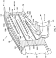
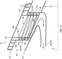
FIGS. 5-7 are partial perspective cutaway illustrations of the vane array with the integral heat exchanger. -
FIG. 8 is a schematic side sectional illustration of a portion of the gas turbine engine with another heat exchange system. -
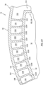
FIG. 9 is a sectional illustration through a portion of the heat exchanger. -
FIG. 10 is a cross-sectional illustration through another portion of the heat exchanger. -
FIG. 11 is a schematic side sectional illustration of a portion of the vane array with another integral heat exchanger. -
FIG. 1 is a schematic side sectional illustration of agas turbine engine 20. Thisgas turbine engine 20 extends along anaxial centerline 22 between anupstream airflow inlet 24 and adownstream airflow exhaust 26. Thegas turbine engine 20 includes afan section 28, acompressor section 29, acombustor section 30 and aturbine section 31. Thecompressor section 29 includes a low pressure compressor (LPC)section 29A and a high pressure compressor (HPC)section 29B. Theturbine section 31 includes a high pressure turbine (HPT)section 31A and a low pressure turbine (LPT)section 31B. - The engine sections 28-31B are arranged sequentially along the
axial centerline 22 within anengine housing 34. Thisengine housing 34 includes an inner case 36 (e.g., a core case) and an outer case 38 (e.g., a fan case). Theinner case 36 may house one or more of theengine sections 29A-31B; e.g., a core of thegas turbine engine 20. Theouter case 38 may house at least thefan section 28. - Each of the
engine sections - The
fan rotor 40 and theLPC rotor 41 are connected to and driven by the LPT rotor 44 through alow speed shaft 46. TheHPC rotor 42 is connected to and driven by theHPT rotor 43 through ahigh speed shaft 48. Theshafts bearings forward bearings 50A may be connected to theinner case 36 by a first support structure, which first support structure may include an inter-compressor case (ICC) 52 between theLPC rotor 41 and theHPC rotor 42. Theaft bearings 50B may be connected to theinner case 36 by a second support structure, which second support structure may include an inter-turbine case (ITC) 54 between theHPT rotor 43 and the LPT rotor 44. The present disclosure, however, is not limited to such an exemplary arrangement. - During operation, air enters the
gas turbine engine 20 through theairflow inlet 24. This air is directed through thefan section 28 and into acore flowpath 54 and abypass flowpath 56. Thecore flowpath 54 extends sequentially through theengine sections core flowpath 54 may be referred to as "core air". Thebypass flowpath 56 extends through a bypass duct, which bypasses the engine core. The air within thebypass flowpath 56 may be referred to as "bypass air". - The core air is compressed by the
LPC rotor 41 and theHPC rotor 42 and directed into a (e.g., annular)combustion chamber 58 of a (e.g., annular)combustor 60 in thecombustor section 30. Fuel is injected into thecombustion chamber 58 and mixed with the compressed core air to provide a fuel-air mixture. This fuel air mixture is ignited and combustion products thereof flow through and sequentially cause theHPT rotor 43 and the LPT rotor 44 to rotate. The rotation of theHPT rotor 43 and the LPT rotor 44 respectively drive rotation of theHPC rotor 42 and theLPC rotor 41 and, thus, compression of the air received from an inlet to thecore flowpath 54. The rotation of the LPT rotor 44 also drives rotation of thefan rotor 40, which propels bypass air through and out of thebypass flowpath 56. The propulsion of the bypass air may account for a majority of thrust generated by thegas turbine engine 20, e.g., more than fifty percent (50%) of engine thrust. Thegas turbine engine 20 of the present disclosure, however, is not limited to the foregoing exemplary thrust ratio. -
FIG. 2 schematically illustrates aheat exchanger system 62 arranged with thecompressor section 29. Thisheat exchanger system 62 includes aninlet circuit 64, a heat exchanger 66 (schematically shown) and anoutlet circuit 68. - The
inlet circuit 64 is configured to provide a heat exchanger fluid to theheat exchanger 66. This heat exchange fluid may be compressed core air bleed from thecore flowpath 54. Theinlet circuit 64 ofFIG. 2 , for example, includes a bleed orifice 70 (or multiple bleed orifices) located downstream of theheat exchanger 66 along thecore flowpath 54. Theinlet circuit 64 is configured to bleed the compressed core air from thecore flowpath 54 through thebleed orifice 70, and direct that bled compressed core air to theheat exchanger 66. Thebleed orifice 70 may be disposed downstream of one or more or each stage 72 (e.g., array of blades) ofHPC rotor 42; e.g., at a downstream end of theHPC rotor 42 along thecore flowpath 54. The present disclosure, however, is not limited to such an exemplary inlet circuit arrangement. - The
heat exchanger 66 is fluidly coupled with and between theinlet circuit 64 and theoutlet circuit 68. Theheat exchanger 66 is integrated with (e.g., configured as part of, configured in, combined with, etc.) another (e.g., internal) component of thegas turbine engine 20, which may reduce weight, space requirements and/or cost of thegas turbine engine 20. Theheat exchanger 66 ofFIG. 2 , for example, is integrated with a vane array 74 (e.g., a nozzle) of thegas turbine engine 20. Thisvane array 74 ofFIG. 2 is configured as part of theinter-compressor case 52. The present disclosure, however, is not limited to such an exemplary configuration. Theengine vane array 74, for example, may be configured elsewhere along thecore flowpath 54. Furthermore, another example of engine components with which theheat exchanger 66 may also or alternatively be integrated include, but are not limited to, a flowpath wall (e.g., a shroud) for thecore flowpath 54 along thecompressor section 29. - The
heat exchanger 66 ofFIG. 2 is configured to exchange heat energy between the compressed core air received from theinlet circuit 64 and the core air flowing through theengine vane array 74. More particularly, theheat exchanger 66 may facilitate a transfer of heat energy out of the relatively warm compressed core air received from theinlet circuit 64 into the relatively cool core air flowing through theengine vane array 74. Theheat exchanger 66 may thereby cool the compressed core air received from theinlet circuit 64 to provide cooled air. Thus, theheat exchanger 66 ofFIG. 2 operates as a cooler. - The
outlet circuit 68 is configured to receive the cooled air from theheat exchanger 66, and provide that cooled air to one or moreother components 75 of thegas turbine engine 20. Examples of the other component(s) 75 include, but are not limited to, one or more of the engine rotors 42-44, one or more of the bearings 50, and one or more seal devices within the engine core. Typically, these other component(s) 75 are disposed within the engine core and, more particularly, radially inboard of an outer peripheral boundary of thecore flowpath 54 and/or theentire core flowpath 54. The present disclosure, however, is not limited to the foregoing example outlet circuit arrangement nor the foregoing exemplary component(s) receiving the cooled air. - Referring to
FIG. 3 , theengine vane array 74 includes aninner platform 76, anouter platform 78 and a plurality ofvanes 80; e.g., airfoil shaped struts. Theinner platform 76 ofFIG. 3 is configured as or otherwise includes aninner flowpath wall 82; e.g., an inner shroud. Theinner platform 76 and itsinner flowpath wall 82 extend circumferentially about (e.g., completely around) theaxial centerline 22, which may thereby provide theinner platform 76 / theinner flowpath wall 82 with a full-hoop (e.g., tubular) body. Theinner flowpath wall 82 extends radially between and to aninner side 84 of theinner flowpath wall 82 and anouter side 86 of theinner flowpath wall 82. At the wallouter side 86, theinner flowpath wall 82 may form an inner peripheral boundary of thecore flowpath 54 through theengine vane array 74. Referring toFIG. 4 , theinner platform 76 and itsinner flowpath wall 82 extend axially along theaxial centerline 22 between and to anupstream end 88 of theinner platform 76 and adownstream end 90 of theinner platform 76. - The
outer platform 78 ofFIG. 3 is configured as or otherwise includes anouter flowpath wall 92; e.g., an outer shroud. Theouter platform 78 and itsouter flowpath wall 92 extend circumferentially about (e.g., completely around) theaxial centerline 22, which may thereby provide theouter platform 78 / theouter flowpath wall 92 with a full-hoop (e.g., tubular) body. Theouter flowpath wall 92 extends radially between and to aninner side 94 of theouter flowpath wall 92 and anouter side 96 of theouter flowpath wall 92. At the wallinner side 94, theouter flowpath wall 92 may form an outer peripheral boundary of thecore flowpath 54 through theengine vane array 74. This outerflowpath wall 92 ofFIG. 3 also circumscribes theinner flowpath wall 82 as well as thevanes 80. Referring toFIG. 4 , theouter platform 78 and itsouter flowpath wall 92 extend axially along theaxial centerline 22 between and to anupstream end 98 of theouter platform 78 and adownstream end 100 of theouter platform 78. - The
vanes 80 ofFIG. 3 are arranged circumferentially about theaxial centerline 22 in an array. Each of thevanes 80 extends radially between and to theinner flowpath wall 82 and theouter flowpath wall 92. Each of thevanes 80 is also connected to (e.g., formed integral with or otherwise attached to) theinner flowpath wall 82 and theouter flowpath wall 92. With this arrangement, each of thevanes 80 extends radially across thecore flowpath 54 between theinner platform 76 and theouter platform 78. Each of thevanes 80 extends laterally (e.g., generally circumferentially) between opposingsides vane 80. Referring toFIG. 4 , each of thevanes 80 extends longitudinally (e.g., generally axially) between aleading edge 104 of thatvane 80 and a trailingedge 106 of thatvane 80, where the vane sides 102 extend longitudinally between and meet at theleading edge 104 and the trailingedge 106. - Referring to
FIGS. 5-7 , theheat exchanger 66 may be partially or completely integrated with (e.g., configured as part of) one or more vane array components (e.g., 76, 78 and/or 80). Theheat exchanger 66 ofFIGS. 5-7 , in particular, includes one or moreheat exchanger inlets 108, aheat exchanger outlet 110 and one or moreheat exchanger passages heat exchanger inlets 108 and theheat exchanger outlet 110. - Referring to
FIGS. 5 and6 , eachheat exchanger inlet 108 may be disposed at a radial outer side of theengine vane array 74. Eachheat exchanger inlet 108 ofFIGS. 5 and6 , for example, is formed by a respective conduit fitting 115 projecting radially out from theouter platform 78. Eachheat exchanger inlet 108 is fluidly coupled with and downstream of the inlet circuit 64 (seeFIG. 2 ). Alternatively, eachheat exchanger inlet 108 may be fluidly coupled with and downstream of adiscrete inlet circuit 64; e.g., seeFIG. 8 . In the embodiments ofFIGS. 5 and6 , theheat exchanger inlets 108 are disposed to opposingsides 102 of a respective one of thevanes 80; referred to below as a heat exchanger vane 118 for ease of description. - The
heat exchanger outlet 110 may be disposed at a radial inner side of theengine vane array 74. Theheat exchanger outlet 110 ofFIGS. 6 and7 , for example, is formed by a conduit fitting 120 projecting radially in from theinner platform 76. Theheat exchanger outlet 110 is fluidly coupled with and upstream of the outlet circuit 68 (seeFIG. 2 ). - Referring to
FIG. 5 , theouter platform passages 112 are arranged with theouter platform 78 and itsouter flowpath wall 92. Each of theseouter platform passages 112 is fluidly coupled with and between a respective one of theheat exchanger inlets 108 and thevane passage 114. - Referring to
FIG. 9 , eachouter platform passage 112 may follow a tortuous (e.g., serpentine, zig-zagged, wavy, etc.) trajectory along theouter flowpath wall 92. Eachouter platform passage 112 ofFIG. 9 , for example, is formed by a plurality ofinterconnected passage segments 116A-J (generally referred to as "116"). Thesepassage segments 116A-J are sequentially arranged along the respective passage trajectory. Thepassage segments 116A-J may be parallel with one another and/or may axially overlap one another. At least one of the passage segments 116 (e.g., 116C) is located circumferentially between a pair of neighboring (e.g., adjacent) passage segments (e.g., 116B and 116D). An axial first (e.g., forward or aft)end 118C of thepassage segment 116C is fluidly coupled with a respective axial first (e.g., forward or aft)end 118B of thepassage segment 116B. An axial second (e.g., aft or forward)end 120C of thepassage segment 116C is fluidly coupled with a respective axial second 120D (e.g., aft or forward) end of thepassage segment 116D. With this arrangement, the respectiveouter platform passage 112 reverses direction from thepassage segment 116B to thepassage segment 116C, and then the respectiveouter platform passage 112 reverses direction again from thepassage segment 116C to thepassage segment 116D. - The
passage segments 116 of a respectiveouter platform passage 112 may be formed by one ormore dividers 122A-I; e.g., axially extending divider walls. Each of thesedividers 122 may fluidly divide (e.g., separate, decouple, etc.) a circumferentially neighboring pair of thepassage segments 116 along their (e.g., axial) lengths except, for example, at the respective ends where thosepassage segments 116 are fluidly coupled with one another. Referring toFIG. 10 , eachdivider 122 also extends radially between and to theouter flowpath wall 92 and anexterior wall 124 of theengine vane array 74 and/or theheat exchanger 66. Thisexterior wall 124 overlaps a (e.g., arcuate) section of theouter flowpath wall 92 and covers theouter platform passages 112; see alsoFIG. 5 . With such an arrangement, eachouter platform passage 112 is formed radially by and between theouter flowpath wall 92 and theexterior wall 124. Theheat exchanger 66 and itsouter platform passages 112 may thereby be integrated with (e.g., embedded into) theengine vane array 74 and itsouter platform 78. - Referring to
FIG. 7 , thevane passage 114 is arranged with and extends through the heat exchanger vane 118. Thevane passage 114 is fluidly coupled with and between theouter platform passages 112 and theheat exchanger outlet 110. - The
vane passage 114 may follow a tortuous (e.g., serpentine, zig-zagged, wavy, etc.) trajectory along opposingwalls vane wall 126A may form an exterior surface of the vane 118 at itsside 102A, and where thevane wall 126B may form an opposing exterior surface of the vane 118 at itsside 102B. Thevane passage 114 ofFIG. 7 , for example, is formed by a plurality ofinterconnected passage segments 128A-E (generally referred to as "128"). Thesepassage segments 128A-E are sequentially arranged along the passage trajectory. Thepassage segments 128A-E may be parallel with one another and/or may axially overlap one another. At least one of the passage segments 128 (e.g., 128C) is located radially between a pair of neighboring (e.g., adjacent) passage segments 128 (e.g., 128B and 128D). An axial first (e.g., forward or aft)end 130C of thepassage segment 128C is fluidly coupled with a respective axial first (e.g., forward or aft)end 130B of thepassage segment 128B. An axial second (e.g., aft or forward)end 132C of thepassage segment 128C is fluidly coupled with a respective axial second (e.g., aft or forward)end 132D of thepassage segment 128D. With this arrangement, thevane passage 114 reverses direction from thepassage segment 128B to thepassage segment 128C, and then thevane passage 114 reverses direction again from thepassage segment 128C to thepassage segment 128D. - The
passage segments 128 of thevane passage 114 may be formed by one ormore dividers 134A-D (generally referred to as "134"); e.g., axially extending divider walls. Each of thesedividers 134 may fluidly divide (e.g., separate, decouple, etc.) a radially neighboring pair of thepassage segments 128 along their (e.g., axial) lengths except, for example, at the respective ends where thosepassage segments 128 are fluidly coupled with one another. Referring toFIG. 6 , eachdivider 134 also extends radially between and to thevane walls 126. With such an arrangement, thevane passage 114 is formed circumferentially by and between thevane walls 126. Theheat exchanger 66 and itsvane passage 114 may thereby be further integrated with (e.g., embedded into) theengine vane array 74 and its heat exchanger vane 118. - The
dividers passage segments FIGS. 7 and9 . However, in other embodiments, one or more or all of thedividers platform passage dividers 122, for example, may extend circumferentially to provide circumferentially extendingpassage segments 116 along theouter flowpath wall 92. In another example, thevane passage dividers 134 may extend radially to provide radially extendingpassage segments 128 within the heat exchanger vane 118. - In some embodiments, referring to
FIGS. 7 and9 , eachheat exchange passage heat exchanger passages vane passage 114 ofFIG. 11 , for example, may be formed between anexterior vane wall 126 of the heat exchanger vane 118 and aninterior vane wall 136 of the heat exchanger vane 118. Thisvane passage 114 may spiral about aninterior bore 138 within the heat exchanger vane 118 formed by theinterior vane wall 136. With such an arrangement, thevane passage 114 extends laterally within the heat exchanger vane 118 between and to theexterior vane wall 126 and theinterior vane wall 136. - In some embodiments, the
heat exchanger 66 may be integrated (e.g. only) with theouter platform 78 and the heat exchanger vane 118 as described above. In other embodiments, however, theheat exchanger 66 may also or alternatively be integrated with theinner platform 76. Theheat exchanger 66, for example, may include an inner platform passage (or passages) fluidly coupled between thevane passage 114 and theoutlet circuit 68. The inner platform passage(s) may be integrated with theinner platform 76 in a similar or different manner as described above with respect to the integration of theouter platform passages 112 with theouter platform 78. In still other embodiments, theheat exchanger 66 may only include heat exchanger passage(s) in a select one of the vane arrangecomponents - The
heat exchanger system 62 and/or itsheat exchanger 66 may be included in various gas turbine engines other than the one described above. Theheat exchanger system 62 and/or itsheat exchanger 66, for example, may be included in a geared gas turbine engine where a gear train connects one or more shafts to one or more rotors in a fan section, a compressor section and/or any other engine section. Alternatively, theheat exchanger system 62 and/or itsheat exchanger 66 may be included in a direct drive gas turbine engine configured without a gear train. Theheat exchanger system 62 and/or itsheat exchanger 66 may be included in a gas turbine engine configured with a single spool, with two spools (e.g., seeFIG. 1 ), or with more than two spools. The gas turbine engine may be configured as a turbofan engine, a turbojet engine, a turboprop engine, a turboshaft engine, a propfan engine, a pusher fan engine or any other type of gas turbine engine. The gas turbine engine may alternatively be configured as an auxiliary power unit (APU) or an industrial gas turbine engine. The present disclosure therefore is not limited to any particular types or configurations of gas turbine engines. - While various embodiments of the present disclosure have been described, it will be apparent to those of ordinary skill in the art that many more embodiments and implementations are possible within the scope of the disclosure. For example, the present disclosure as described herein includes several aspects and embodiments that include particular features. Although these features may be described individually, it is within the scope of the present disclosure that some or all of these features may be combined with any one of the aspects and remain within the scope of the disclosure. Accordingly, the present disclosure is not to be restricted except in light of the attached claims and their equivalents.
Claims (15)
- An apparatus for a gas turbine engine, comprising:a vane array including an inner platform, an outer platform and a plurality of vanes, the inner platform extending circumferentially about a centerline and forming an inner peripheral boundary of a flowpath through the vane array, the outer platform extending circumferentially about the centerline and forming an outer peripheral boundary of the flowpath through the vane array, and the plurality of vanes extending across the flowpath between the inner platform and the outer platform; anda heat exchanger integrated with the vane array, the heat exchanger comprising a passage following a tortuous trajectory along a first wall of the vane array.
- The apparatus of claim 1, wherein the tortuous trajectory comprises a serpentine trajectory.
- The apparatus of claim 1 or 2, whereinthe passage includes a first passage segment, a second passage segment and a third passage segment sequentially arranged along the tortuous trajectory; andthe second passage segment overlaps and is between the first passage segment and the third passage segment, optionally wherein the second passage segment is parallel with the first passage segment and the third passage segment.
- The apparatus of claim 3, wherein:
the second passage segment axially overlaps and is circumferentially or radially between the first passage segment and the third passage segment. - The apparatus of any preceding claim, wherein the outer platform comprises the first wall or the inner platform comprises the first wall.
- The apparatus of any of claims 1 to 4, wherein a first of the plurality of vanes comprises the first wall.
- The apparatus of claim 6, whereinthe first wall forms a first exterior side surface of the first of the plurality of vanes;the first of the plurality of vanes further comprises a second wall that forms an interior surface or a second exterior side surface of the first of the plurality of vanes; andthe passage extends laterally within the first of the plurality of vanes between the first wall and the second wall.
- The apparatus of claim 6 or 7, wherein the tortuous trajectory spirals about an interior bore of the first of the plurality of vanes.
- The apparatus of any preceding claim, wherein the heat exchanger is configured to exchange heat energy through the first wall between a first gas flowing through the flowpath and a second gas flowing through the passage.
- The apparatus of any preceding claim, whereinthe vane array further includes a second wall and a plurality of dividers extending between the first wall and the second wall; andthe plurality of dividers are arranged to provide the passage with the tortuous trajectory.
- The apparatus of any preceding claim, further comprising:a compressor section comprising a compressor stage downstream of the vane array along the flowpath;the passage configured to receive air compressed by the compressor stage and bled from the flowpath.
- The apparatus of any preceding claim, whereinthe passage is fluidly coupled between a heat exchanger inlet and a heat exchanger outlet;the heat exchanger inlet is disposed at an outer side of the vane array; andthe heat exchanger outlet is disposed at an inner side of the vane array.
- An apparatus for a gas turbine engine, comprising:a compressor section component comprising a wall and a heat exchange passage;the wall extending axially along and circumferentially about a centerline, and the wall radially between and at least partially forming a core flowpath through the compressor section and the heat exchange passage; andthe heat exchange passage including a first passage segment, a second passage segment and a third passage segment, the second passage segment fluidly coupled between the first passage segment and the third passage segment, and the second passage segment axially overlapping and circumferentially between the first passage segment and the third passage segment.
- The apparatus of claim 13, wherein:the compressor section component is configured as a vane array including an inner platform, an outer platform and a plurality of vanes extending through the flowpath between the inner platform and the outer platform, and the outer platform comprises the wall; and/orthe heat exchange passage extends between an inlet and an outlet, and the inlet is radially outboard of the outlet.
- An apparatus for a gas turbine engine, comprising:a vane array including an inner platform, an outer platform and a plurality of vanes, the inner platform extending circumferentially about a centerline and forming an inner peripheral boundary of a flowpath through the vane array, the outer platform extending circumferentially about the centerline and forming an outer peripheral boundary of the flowpath through the vane array, and the plurality of vanes extending across the flowpath between the inner platform and the outer platform; anda heat exchanger integrated with the vane array, the heat exchanger comprising a passage extending along and formed by the outer platform and a first of the plurality of vanes.
Applications Claiming Priority (1)
| Application Number | Priority Date | Filing Date | Title |
|---|---|---|---|
| US17/976,397 US11873758B1 (en) | 2022-10-28 | 2022-10-28 | Gas turbine engine component with integral heat exchanger |
Publications (2)
| Publication Number | Publication Date |
|---|---|
| EP4361423A2 true EP4361423A2 (en) | 2024-05-01 |
| EP4361423A3 EP4361423A3 (en) | 2024-09-18 |
Family
ID=88600397
Family Applications (1)
| Application Number | Title | Priority Date | Filing Date |
|---|---|---|---|
| EP23206825.4A Pending EP4361423A3 (en) | 2022-10-28 | 2023-10-30 | Gas turbine engine component with integral heat exchanger |
Country Status (3)
| Country | Link |
|---|---|
| US (1) | US11873758B1 (en) |
| EP (1) | EP4361423A3 (en) |
| CA (1) | CA3218364A1 (en) |
Families Citing this family (1)
| Publication number | Priority date | Publication date | Assignee | Title |
|---|---|---|---|---|
| US12607132B1 (en) | 2025-02-17 | 2026-04-21 | General Electric Company | Heat exchanger assembly configuration for a gas turbine engine |
Family Cites Families (21)
| Publication number | Priority date | Publication date | Assignee | Title |
|---|---|---|---|---|
| BE495947A (en) * | 1949-05-30 | 1950-09-16 | ||
| IT1137783B (en) | 1981-08-03 | 1986-09-10 | Nuovo Pignone Spa | HEAT EXCHANGER INTEGRATED WITH THE STATIC CASE OF A GAS TURBINE |
| US4721433A (en) * | 1985-12-19 | 1988-01-26 | United Technologies Corporation | Coolable stator structure for a gas turbine engine |
| US5313778A (en) | 1992-12-10 | 1994-05-24 | United Technologies Corporation | Automatic turbine engine bleed valve control for enhanced fuel management |
| US6254333B1 (en) * | 1999-08-02 | 2001-07-03 | United Technologies Corporation | Method for forming a cooling passage and for cooling a turbine section of a rotary machine |
| US7377098B2 (en) * | 2004-08-26 | 2008-05-27 | United Technologies Corporation | Gas turbine engine frame with an integral fluid reservoir and air/fluid heat exchanger |
| US9476313B2 (en) * | 2012-12-21 | 2016-10-25 | United Technologies Corporation | Gas turbine engine including a pre-diffuser heat exchanger |
| FR3034474B1 (en) * | 2015-04-01 | 2019-08-09 | Safran Aircraft Engines | TURBOMACHINE EQUIPPED WITH A DRAINING SECTOR AND A COOLING CIRCUIT |
| US10422233B2 (en) * | 2015-12-07 | 2019-09-24 | United Technologies Corporation | Baffle insert for a gas turbine engine component and component with baffle insert |
| GB201607791D0 (en) | 2016-05-04 | 2016-06-15 | Rolls Royce | Method to determine a state of a valve and valve monitoring apparatus |
| US11078795B2 (en) * | 2017-11-16 | 2021-08-03 | General Electric Company | OGV electroformed heat exchangers |
| US11022037B2 (en) * | 2018-01-04 | 2021-06-01 | General Electric Company | Gas turbine engine thermal management system |
| FR3078367B1 (en) * | 2018-02-23 | 2021-09-03 | Safran Aircraft Engines | TURBOMACHINE WITH A HEAT EXCHANGER IN THE SECONDARY VEIN |
| FR3093530B1 (en) * | 2019-03-08 | 2021-04-02 | Safran Aircraft Engines | Turbomachine comprising a heat exchanger formed in a platform |
| US11274602B2 (en) | 2019-05-24 | 2022-03-15 | Pratt & Whitney Canada Corp. | Air cooler for gas turbine engine |
| US11268392B2 (en) * | 2019-10-28 | 2022-03-08 | Rolls-Royce Plc | Turbine vane assembly incorporating ceramic matrix composite materials and cooling |
| GB2589125B (en) * | 2019-11-21 | 2022-10-19 | Gkn Aerospace Sweden Ab | Heat exchanger integration |
| US10975770B1 (en) | 2019-12-05 | 2021-04-13 | Hamilton Sundstrand Corporation | Integral engine case precooler |
| US11454176B2 (en) | 2020-01-31 | 2022-09-27 | Pratt & Whitney Canada Corp. | System and method for monitoring a bleed valve of a gas turbine engine |
| KR102510535B1 (en) * | 2021-02-23 | 2023-03-15 | 두산에너빌리티 주식회사 | Ring segment and turbo-machine comprising the same |
| DE202022103117U1 (en) * | 2022-06-01 | 2022-07-04 | Borgwarner Inc. | Housing |
-
2022
- 2022-10-28 US US17/976,397 patent/US11873758B1/en active Active
-
2023
- 2023-10-27 CA CA3218364A patent/CA3218364A1/en active Pending
- 2023-10-30 EP EP23206825.4A patent/EP4361423A3/en active Pending
Also Published As
| Publication number | Publication date |
|---|---|
| CA3218364A1 (en) | 2024-04-28 |
| US11873758B1 (en) | 2024-01-16 |
| EP4361423A3 (en) | 2024-09-18 |
Similar Documents
| Publication | Publication Date | Title |
|---|---|---|
| US11022037B2 (en) | Gas turbine engine thermal management system | |
| US10989411B2 (en) | Heat exchanger for turbo machine | |
| EP3845748B1 (en) | Turbine engine system with heat exchanger in bypassable secondary duct | |
| CN114991961B (en) | Multi-fluid heat exchanger | |
| EP4067623B1 (en) | Turbine engine with cooling air conduit | |
| EP4464881A1 (en) | Pressure control for bifurcated flow of a turbine engine | |
| US11873758B1 (en) | Gas turbine engine component with integral heat exchanger | |
| EP4647665A2 (en) | Separating airflows within a turbine engine | |
| EP4588805A2 (en) | Framed heat exchanger for aircraft propulsion system | |
| EP4582673A1 (en) | Cooling nozzle vanes of a turbine engine | |
| US20250075662A1 (en) | Turbine Engine having First and Second Accessory Gearboxes | |
| EP4411116A1 (en) | Buffer air system for a bearing compartment of a gas turbine | |
| US11021961B2 (en) | Rotor assembly thermal attenuation structure and system | |
| US12631143B2 (en) | Gas turbine engine with heat exchanger assembly | |
| EP4560113A1 (en) | Cooling nozzle vanes of a turbine engine | |
| EP4600466A1 (en) | Cooling nozzle vanes of a turbine engine | |
| CN112431674A (en) | Counter-rotating turbine with reversing reduction gearbox | |
| US20260009334A1 (en) | Notched turbine vane baffle | |
| EP4495383A1 (en) | Turbine engine vane array structure with air particle separator | |
| US12234748B2 (en) | Gas turbine engine having outlet guide vanes | |
| US12473835B2 (en) | Vane array structure with recessed stator vanes | |
| US20250290452A1 (en) | Turbine engine with accessory gearbox | |
| EP4685341A1 (en) | Diffuser-turbine flow network | |
| EP3569819A1 (en) | Multiple source impingement baffles for gas turbine engine components |
Legal Events
| Date | Code | Title | Description |
|---|---|---|---|
| PUAI | Public reference made under article 153(3) epc to a published international application that has entered the european phase |
Free format text: ORIGINAL CODE: 0009012 |
|
| STAA | Information on the status of an ep patent application or granted ep patent |
Free format text: STATUS: THE APPLICATION HAS BEEN PUBLISHED |
|
| AK | Designated contracting states |
Kind code of ref document: A2 Designated state(s): AL AT BE BG CH CY CZ DE DK EE ES FI FR GB GR HR HU IE IS IT LI LT LU LV MC ME MK MT NL NO PL PT RO RS SE SI SK SM TR |
|
| PUAL | Search report despatched |
Free format text: ORIGINAL CODE: 0009013 |
|
| AK | Designated contracting states |
Kind code of ref document: A3 Designated state(s): AL AT BE BG CH CY CZ DE DK EE ES FI FR GB GR HR HU IE IS IT LI LT LU LV MC ME MK MT NL NO PL PT RO RS SE SI SK SM TR |
|
| RIC1 | Information provided on ipc code assigned before grant |
Ipc: F01D 9/04 20060101ALI20240813BHEP Ipc: F02C 7/141 20060101AFI20240813BHEP |
|
| STAA | Information on the status of an ep patent application or granted ep patent |
Free format text: STATUS: REQUEST FOR EXAMINATION WAS MADE |
|
| 17P | Request for examination filed |
Effective date: 20250318 |