EP4361419A1 - Brennstoffsystem für gasturbinenmotor - Google Patents
Brennstoffsystem für gasturbinenmotor Download PDFInfo
- Publication number
- EP4361419A1 EP4361419A1 EP23199576.2A EP23199576A EP4361419A1 EP 4361419 A1 EP4361419 A1 EP 4361419A1 EP 23199576 A EP23199576 A EP 23199576A EP 4361419 A1 EP4361419 A1 EP 4361419A1
- Authority
- EP
- European Patent Office
- Prior art keywords
- fuel
- burner
- gas turbine
- turbine engine
- hydrogen
- Prior art date
- Legal status (The legal status is an assumption and is not a legal conclusion. Google has not performed a legal analysis and makes no representation as to the accuracy of the status listed.)
- Pending
Links
- 239000000446 fuel Substances 0.000 title claims abstract description 157
- UFHFLCQGNIYNRP-UHFFFAOYSA-N Hydrogen Chemical compound [H][H] UFHFLCQGNIYNRP-UHFFFAOYSA-N 0.000 claims abstract description 69
- 239000001257 hydrogen Substances 0.000 claims abstract description 69
- 229910052739 hydrogen Inorganic materials 0.000 claims abstract description 69
- 239000007789 gas Substances 0.000 claims abstract description 58
- 238000011084 recovery Methods 0.000 claims abstract description 14
- 238000002485 combustion reaction Methods 0.000 claims description 12
- 238000010438 heat treatment Methods 0.000 claims description 6
- 238000000034 method Methods 0.000 claims description 4
- 238000005086 pumping Methods 0.000 claims description 3
- 230000001419 dependent effect Effects 0.000 claims 3
- 238000002347 injection Methods 0.000 description 11
- 239000007924 injection Substances 0.000 description 11
- 230000001965 increasing effect Effects 0.000 description 7
- 238000010586 diagram Methods 0.000 description 6
- 239000007788 liquid Substances 0.000 description 4
- 239000002918 waste heat Substances 0.000 description 4
- 239000012530 fluid Substances 0.000 description 3
- 239000002699 waste material Substances 0.000 description 3
- CURLTUGMZLYLDI-UHFFFAOYSA-N Carbon dioxide Chemical compound O=C=O CURLTUGMZLYLDI-UHFFFAOYSA-N 0.000 description 2
- 230000006835 compression Effects 0.000 description 2
- 238000007906 compression Methods 0.000 description 2
- 238000001816 cooling Methods 0.000 description 2
- 230000001141 propulsive effect Effects 0.000 description 2
- 238000011144 upstream manufacturing Methods 0.000 description 2
- 239000004215 Carbon black (E152) Substances 0.000 description 1
- 238000004378 air conditioning Methods 0.000 description 1
- QVGXLLKOCUKJST-UHFFFAOYSA-N atomic oxygen Chemical compound [O] QVGXLLKOCUKJST-UHFFFAOYSA-N 0.000 description 1
- 230000009286 beneficial effect Effects 0.000 description 1
- 230000000740 bleeding effect Effects 0.000 description 1
- 229910002092 carbon dioxide Inorganic materials 0.000 description 1
- 239000001569 carbon dioxide Substances 0.000 description 1
- 150000001875 compounds Chemical class 0.000 description 1
- 238000010276 construction Methods 0.000 description 1
- 238000005485 electric heating Methods 0.000 description 1
- 230000005611 electricity Effects 0.000 description 1
- 238000000605 extraction Methods 0.000 description 1
- 238000010304 firing Methods 0.000 description 1
- 229930195733 hydrocarbon Natural products 0.000 description 1
- 150000002430 hydrocarbons Chemical class 0.000 description 1
- 239000000411 inducer Substances 0.000 description 1
- 230000001939 inductive effect Effects 0.000 description 1
- 238000009434 installation Methods 0.000 description 1
- 238000002156 mixing Methods 0.000 description 1
- 239000001301 oxygen Substances 0.000 description 1
- 229910052760 oxygen Inorganic materials 0.000 description 1
- 238000010248 power generation Methods 0.000 description 1
- 238000009834 vaporization Methods 0.000 description 1
Images


Classifications
-
- F—MECHANICAL ENGINEERING; LIGHTING; HEATING; WEAPONS; BLASTING
- F02—COMBUSTION ENGINES; HOT-GAS OR COMBUSTION-PRODUCT ENGINE PLANTS
- F02C—GAS-TURBINE PLANTS; AIR INTAKES FOR JET-PROPULSION PLANTS; CONTROLLING FUEL SUPPLY IN AIR-BREATHING JET-PROPULSION PLANTS
- F02C7/00—Features, components parts, details or accessories, not provided for in, or of interest apart form groups F02C1/00 - F02C6/00; Air intakes for jet-propulsion plants
- F02C7/22—Fuel supply systems
- F02C7/224—Heating fuel before feeding to the burner
-
- F—MECHANICAL ENGINEERING; LIGHTING; HEATING; WEAPONS; BLASTING
- F02—COMBUSTION ENGINES; HOT-GAS OR COMBUSTION-PRODUCT ENGINE PLANTS
- F02C—GAS-TURBINE PLANTS; AIR INTAKES FOR JET-PROPULSION PLANTS; CONTROLLING FUEL SUPPLY IN AIR-BREATHING JET-PROPULSION PLANTS
- F02C3/00—Gas-turbine plants characterised by the use of combustion products as the working fluid
- F02C3/20—Gas-turbine plants characterised by the use of combustion products as the working fluid using a special fuel, oxidant, or dilution fluid to generate the combustion products
- F02C3/22—Gas-turbine plants characterised by the use of combustion products as the working fluid using a special fuel, oxidant, or dilution fluid to generate the combustion products the fuel or oxidant being gaseous at standard temperature and pressure
-
- F—MECHANICAL ENGINEERING; LIGHTING; HEATING; WEAPONS; BLASTING
- F02—COMBUSTION ENGINES; HOT-GAS OR COMBUSTION-PRODUCT ENGINE PLANTS
- F02C—GAS-TURBINE PLANTS; AIR INTAKES FOR JET-PROPULSION PLANTS; CONTROLLING FUEL SUPPLY IN AIR-BREATHING JET-PROPULSION PLANTS
- F02C7/00—Features, components parts, details or accessories, not provided for in, or of interest apart form groups F02C1/00 - F02C6/00; Air intakes for jet-propulsion plants
- F02C7/12—Cooling of plants
- F02C7/14—Cooling of plants of fluids in the plant, e.g. lubricant or fuel
-
- F—MECHANICAL ENGINEERING; LIGHTING; HEATING; WEAPONS; BLASTING
- F05—INDEXING SCHEMES RELATING TO ENGINES OR PUMPS IN VARIOUS SUBCLASSES OF CLASSES F01-F04
- F05D—INDEXING SCHEME FOR ASPECTS RELATING TO NON-POSITIVE-DISPLACEMENT MACHINES OR ENGINES, GAS-TURBINES OR JET-PROPULSION PLANTS
- F05D2260/00—Function
- F05D2260/20—Heat transfer, e.g. cooling
- F05D2260/213—Heat transfer, e.g. cooling by the provision of a heat exchanger within the cooling circuit
Definitions
- This disclosure relates to fuel systems for hydrogen-fuelled aero gas turbine engines.
- the invention is directed towards a gas turbine engine fuel system comprising a hydrogen fuel preheater for heating cryogenically-stored hydrogen fuel prior to injection into gas turbine engines, gas turbine engines incorporating such gas turbines, and methods of operating such gas turbines.
- one such gas turbine engine fuel system comprises:
- the power recovery device comprises a nozzle arranged to expand exhaust gasses to produce thrust.
- waste he at and pressure from the burner is recovered, and used for propulsive thrust, thereby reducing Thrust Specific Fuel Consumption (TSFC) of the gas turbine engine.
- TSFC Thrust Specific Fuel Consumption
- the nozzle is provided separately to a gas turbine engine core nozzle.
- the exhaust communicates with a gas turbine engine core downstream of a gas turbine engine turbine stage, and the nozzle comprises an engine core nozzle.
- noise may be reduced by shielding the high velocity nozzle flow within the engine core flow.
- the power recovery device is a burner exhaust turbine.
- the waste heat and pressure in the burner exhaust flow can be used to power additional equipment via the exhaust turbine.
- the burner exhaust turbine is mechanically coupled to a load such as an electrical generator or engine accessory.
- the gas turbine engine fuel system comprises a fuel pump configured to pump the hydrogen fuel.
- the burner exhaust turbine is configured to drive the engine fuel pump.
- the burner exhaust turbine is directly coupled to the engine fuel pump to directly drive the engine fuel pump.
- the burner exhaust turbine is coupled to an electrical generator, the engine fuel pump is coupled to an electric motor, and the burner exhaust turbine is configured to drive the engine fuel pump electrically via the generator and motor.
- the burner exhaust turbine is configured to drive an auxiliary air compressor.
- the burner is arranged to be supplied with air for combustion from a core compressor bleed of a gas turbine engine.
- air for combustion from a core compressor bleed of a gas turbine engine.
- high pressure air is provided for combustion in the burner, thereby increasing burner exhaust turbine efficiency.
- the auxiliary air compressor is configured to further compress core compressor bleed air prior to delivery to the burner.
- the air compressor, burner, and burner turbine form a Brayton cycle arrangement (i.e. a gas turbine engine), in which compressed air for the burner is provided by a compressor which is driven by a turbine, which is in turn driven by hot gases provided by the burner.
- a Brayton cycle arrangement i.e. a gas turbine engine
- compressed air for the burner is provided by a compressor which is driven by a turbine, which is in turn driven by hot gases provided by the burner.
- Such an arrangement is self-sustaining in operation.
- by providing additional compression for the burner using the auxiliary compressor lower pressure bleed air is required for the burner, which increases efficiency of the main propulsive gas turbine engine.
- the auxiliary air compressor is configured to provide air to a hydrogen fuel cell.
- a hydrogen-fuelled gas turbine engine comprising a fuel system in accordance with the first aspect..
- the gas turbine engine comprises:
- a method of delivering cryogenically-stored hydrogen fuel to a gas turbine engine comprising:
- the method further comprises bleeding compressed air from a compressor of the gas turbine engine and supplying the compressed air to the burner to burn with the portion of hydrogen fuel diverted from the main fuel conduit.
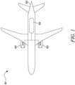
- FIG. 1 A hydrogen-fuelled airliner is illustrated in Figure 1 .
- the airliner 101 is of substantially conventional tube-and-wing twinjet configuration with a central fuselage 102 and substantially identical underwing-mounted turbofan engines 103.
- the turbofan engines 103 are geared turbofan engines.
- the hydrogen storage tank 104 is a cryogenic hydrogen storage tank and thus stores the hydrogen fuel in a liquid state, in a specific example at 25 kelvin.
- the hydrogen fuel is pressurised to a pressure from around 1 bar to around 3 bar, in a specific example 4 bar.
- FIG. 2 A block diagram of one of the turbofan engines 103 is shown in Figure 2 .
- the turbofan engine 103 comprises a core gas turbine 201.
- the core gas turbine 201 comprises, in fluid flow series, a low-pressure compressor 202, a high-pressure compressor 204, a fuel injection system 206, a combustor 207, a high-pressure turbine 208, a low-pressure turbine 209, and a core nozzle 210.
- the high-pressure compressor 204 is driven by the high-pressure turbine 208 via a first shaft 211
- the low-pressure compressor 203 is driven by the low-pressure turbine 209 via a second shaft 212.
- the core gas turbine could be of three-shaft configuration.
- the turbofan engines 103 are geared turbofan engines.
- the low-pressure turbine 209 drives a fan 213 via a reduction gearbox 214.
- the reduction gearbox receives input drive from the second shaft 212 and provides output drive to the fan 213 via a fan shaft 215.
- the reduction gearbox 214 is an epicyclic reduction gearbox. In a specific embodiment, it is a planetary reduction gearbox. Alternatively, it may be a star reduction gearbox, or a compound epicyclic reduction gearbox. As a further alternative, the reduction gearbox 214 could be a layshaft-type reduction gearbox or any other type of reduction gearbox. It will also be appreciated that the principles disclosed herein may be applied to a direct-drive type turbofan engine, i.e. in which there is no reduction gearbox between the low-pressure turbine and the fan.
- hydrogen fuel is pumped from the hydrogen storage tank 104 by a pump 216 and into a main fuel conduit 217 which ultimately delivers fuel to the fuel injection system 206.
- the pump 216 is high-speed centrifugal pump.
- the centrifugal pump comprises an axial inducer to minimise the required inlet pressure and to accommodate multiphase flow in addition to the centrifugal impeller for developing the majority of the required pressure rise.
- a piston-type pump could be used.
- the pump 216 is located inside the hydrogen storage tank 104. In this way leakage of hydrogen fuel past pump seals etc. is accommodated.
- the pump 216 is driven by an electric motor 317.
- the drive means for the pump 216 are also located in the hydrogen storage tank 104.
- the injection temperature is from 250 to 300 kelvin, for example 250 kelvin.
- a preheater 218 is therefore provided for heating of the hydrogen fuel. In the present embodiment, this takes place between the pump 216 and the fuel injection system 206. In an embodiment, the preheater 218 is configured to raise the temperature of the hydrogen fuel to the required injection temperature. The heating may provide a phase change (for example from liquid to supercritical or to gas), or the fluid may remain in a supercritical state after heating by the preheater.
- the preheater 218 is configured to raise the temperature of the hydrogen fuel to an intermediate temperature less than the injection temperature. This could for example be from 60 to 200 kelvin, for example 150 kelvin.
- the preheater 218 comprises an offtake 220 to divert a portion of the hydrogen fuel from the main fuel conduit 217.
- the amount of hydrogen bled from the main fuel conduit 217 is controlled by a valve (not shown).
- the valve is controlled actively, for example in response to the temperature of the fuel at the fuel injection system 206.
- the valve may be passively controlled. In operation, of the order of around 1 percent of the hydrogen fuel flow through the main fuel conduit 217 is bled for use in the preheater 218.
- the preheater 218 vaporises the hydrogen fuel in the main fuel conduit 217 by combustion of the bled fuel in a burner 222 located in heat exchange relationship with the main fuel conduit 217.
- the burner 222 is concentric around the main fuel conduit 217 and hence the burner 222 itself comprises the heat exchanger for transferring heat to hydrogen fuel in the main fuel conduit 217. It will of course be appreciated that other arrangements are possible.
- the burner 222 could be positioned separately from the main fuel conduit 217 and exhaust gases therefrom directed through a dedicated heat exchanger unit 224.
- Such a unit may comprise a first pass for the flow of hot exhaust products from the burner 222, and a second pass for the main fuel flow which then vaporises as it flows through the heat exchanger unit.
- air for combustion with the bled hydrogen fuel is bled from the high-pressure compressor 204 from a compressor bleed 226 via a bleed air line 228.
- it may be bled from the low-pressure compressor 202. It will be appreciated that the air for combustion could be obtained from any other suitable location.
- the air and the bled hydrogen fuel are mixed in a pre-mixer 230 prior to supply to the burner 222, although in alternative embodiments it may be directly co-injected into the burner with the hydrogen fuel instead.
- the products of combustion from the burner 222 are not mixed with the fuel in the main fuel conduit 217.
- the preheater 218 therefore differs from a pre-burner system as used in staged combustion cycle rocket engines.
- the preheater 218 comprises a pre-heater 230 to ensure that the bled hydrogen fuel boils prior to mixing with air in the pre-mixer.
- the pre-heater 230 comprises an electric heating element, for example an inductive coil.
- the pre-heater 230 could be simply configured as a boil volume, in which the ambient conditions therein contain sufficient enthalpy to boil the initial flow of bled hydrogen fuel prior to delivery to the pre-mixer and the burner 222.
- the fuel delivery system 201 and fuel injection system 206 may be used in an embodiment of the core gas turbine 201 implementing a simple cycle as described with reference to Figure 2 , possibly with fuel cooling of engine or gearbox oil or cooling air.
- the core gas turbine engine 201 may implement a complex cycle.
- Combustion products from the burner 222 are exhausted into an exhaust line 232 provided downstream of the heat exchanger 224.
- the temperature through the exhaust is relatively low in all cases, in view of the heat transfer to the hydrogen fuel via the heat exchanger 224.
- mass flow through the exhaust is relatively low, in view of the relatively small amount of fuel used by the burner.
- the available pressure is relatively high.
- energy from the exhaust flow can be recovered by a power recovery device configured to extract power from exhaust gasses of the burner downstream of the heat-exchanger.
- the power recovery device is an exhaust nozzle 234 in the form of a convergent-divergent nozzle, arranged to provide thrust.
- the convergent-divergent nozzle may be arranged to provide exhaust flow which exits into either the core nozzle or the nacelle to provide thrust to augment that provided by the engine core and fan.
- the temperature through the exhaust is relatively low in all cases, in view of the heat transfer to the hydrogen fuel via the heat exchanger 224.
- mass flow through the exhaust is relatively low, in view of the relatively small amount of fuel used by the burner.
- the available pressure is relatively high.
- flow expanded through a convergent-divergent nozzle can be "choked”, i.e. accelerated to supersonic speeds in the convergent section, before being expanded again in the divergent section.
- Such an arrangement is known as a "De Leval" nozzle, and is an efficient means of generating thrust.
- FIG. 3 A second embodiment of the gas turbine engine 203 is shown in figure 3 .
- the power recovery device is in the form of a turbine 340 in place of the nozzle 234.
- the stream turbine is of conventional construction, and is configured to receive a hot, high pressure input from the exhaust line 232, and exhaust spent, low pressure into the core nozzle or bypass stream.
- the turbine 340 is coupled to a load, which in this embodiment comprises a generator 344, via a mechanical shaft 342. As such, the turbine 340 can be used to generate electrical power from waste energy in the pre-burner exhaust stream. As will be understood, different loads such as engine or aircraft hydraulic pumps could be employed in place of the generator 344.
- an electric motor may be provided for re-introducing shaft power into the gas turbine engine, in a hybrid propulsion configuration.
- the generator 344 can be replaced by different loads.
- Figure 4 shows an embodiment in which the generator 342 is replaced by an auxiliary compressor 450 driven by the turbine 340. Consequently, high pressure air can be provided for various purposes.
- the compressor 450 is utilised to power pneumatic systems such as actuators.
- the compressor air is used to provide cabin pressurisation and air conditioning. As such, compressor bleed air requirements are reduced, thereby improving compressor operability and reducing compressor design constraints.
- Figure 5 shows a further embodiment, in which an auxiliary compressor is used in a different manner.
- an auxiliary compressor 551 is driven by the burner turbine 340 by a shaft 342.
- the auxiliary compressor 541 is placed in the air flow path of the bleed air from the main gas turbine engine core compressor 204, upstream of the burner 222.
- the auxiliary compressor is configured to further compress compressed bleed air prior to introduction to the burner 222.
- the auxiliary compressor 551, burner 222 and burner turbine 340 act as a Brayton cycle gas turbine engine.
- Such a cycle may produce excess shaft power, which can be used for various purposes.
- the shaft 342 may optionally mechanically drive the hydrogen fuel pump 216 either alone, or in combination with an electric motor. Consequently, pumping losses are reduced, and therefore overall system efficiency is increased.
- the minimum pressure requirements of the burner 222 can be met using lower initial pressure flow from the engine core compressor 204.
- an earlier compressor stage bleed is utilised, as shown in figure 5 .
- bleed flow can be taken from the low-pressure compressor 202 rather than the high-pressure compressor 204, or from an earlier stage of the high-pressure compressor 204 compared to the embodiments shown in figures 1 to 4 .
- less pneumatic power is drawn from the main engine core, thereby increasing core overall pressure ratio or reducing turbine load.
- core engine thermal efficiency is increased, thereby further increasing overall engine fuel efficiency.
- a higher pressure air flow may be provided to the burner 222 compared to the embodiments in figures 1 to 4 .
- the burner can be physically smaller and lighter, while providing the same quantity of heat to the main fuel flow.
- the system may be easier to start, requiring less main engine compressor pressure to provide combustion in view of the additional pressure rise provided by the auxiliary compressor 551.
- the electric machine can be driven by the turbine 340 to be utilised as an electric generator during operation, and may be adapted as an electric motor to drive at least the auxiliary compressor 551 and optionally the fuel pump 216 during starting.
- the burner 218 can be operated independently of the main gas turbine engine 203 to raise fuel temperature for starting, and can even be used as an auxiliary power unit (APU) to start the main engine via a main engine starter-generator (not shown) using power from the electric machine 317, or provide auxiliary power for aircraft systems when the aircraft is non-operational.
- APU auxiliary power unit
- the hydrogen compressor 216 may be powered by a separate turbine (not shown) and shaft (not shown) provided downstream or upstream in burner flow to the turbine 340.
- the power and rotational speed requirements of the auxiliary compressor 551, hydrogen pump and I or electric machine 317 can be appropriately matched.
- An additional feature of the embodiment of figure 5 is the provision of an exhaust line 232 which flows into the core engine exhaust either within or aft of the turbine 209. As such, additional power can be extracted from the exhaust, either as thrust, or as motive power introduced to the main core gas turbine engine.
- FIG. 6 shows an embodiment of the gas turbine engine 203 having a hydrogen fuel cell arrangement.
- the hydrogen fuel cell arrangement comprises a hydrogen fuel cell 562, which takes oxygen from air and fuel in the form of hydrogen to generate electricity. Waste heat from the fuel cell is reintroduced into the fuel system downstream of the fuel cell via one or more heat exchangers 564, 566.
- the air for the hydrogen fuel cell is provided by the auxiliary compressor 450, while the gaseous hydrogen fuel is tapped off from the main fuel line 217 downstream of the heat exchanger 224.
- a dedicated high pressure air flow is provided for the hydrogen fuel cell, which is at least partly independent of engine operating conditions.
- power for the air compression is provided from waste power as a result of the gas turbine engine fuel system, thereby increasing overall operational efficiency of the propulsion system as a whole.
- the fuel cell can be operated as required.
- waste heat from the fuel cell 562 is exhausted back into the main gas turbine engine 10, thereby further increasing operational efficiency.
Landscapes
- Engineering & Computer Science (AREA)
- Chemical & Material Sciences (AREA)
- Combustion & Propulsion (AREA)
- Mechanical Engineering (AREA)
- General Engineering & Computer Science (AREA)
- Engine Equipment That Uses Special Cycles (AREA)
Applications Claiming Priority (1)
| Application Number | Priority Date | Filing Date | Title |
|---|---|---|---|
| GBGB2215721.8A GB202215721D0 (en) | 2022-10-24 | 2022-10-24 | Gas turbine engine fuel system |
Publications (1)
| Publication Number | Publication Date |
|---|---|
| EP4361419A1 true EP4361419A1 (de) | 2024-05-01 |
Family
ID=84818625
Family Applications (1)
| Application Number | Title | Priority Date | Filing Date |
|---|---|---|---|
| EP23199576.2A Pending EP4361419A1 (de) | 2022-10-24 | 2023-09-26 | Brennstoffsystem für gasturbinenmotor |
Country Status (3)
| Country | Link |
|---|---|
| US (1) | US20240229717A9 (de) |
| EP (1) | EP4361419A1 (de) |
| GB (1) | GB202215721D0 (de) |
Citations (5)
| Publication number | Priority date | Publication date | Assignee | Title |
|---|---|---|---|---|
| US4942733A (en) * | 1987-03-26 | 1990-07-24 | Sundstrand Corporation | Hot gas generator system |
| CA2247197A1 (en) * | 1996-02-26 | 1997-08-28 | David John Huber | Hydrogen fueled power plant with recuperation |
| US20130276433A1 (en) * | 2010-03-24 | 2013-10-24 | Kawasaki Jukogyo Kabushiki Kaisha | Lean-fuel gas turbine engine |
| US20200088102A1 (en) * | 2018-09-14 | 2020-03-19 | United Technologies Corporation | Hybrid expander cycle with intercooling and turbo-generator |
| US20220099020A1 (en) * | 2020-09-30 | 2022-03-31 | Rolls-Royce Plc | Hydrogen fuel vaporiser |
-
2022
- 2022-10-24 GB GBGB2215721.8A patent/GB202215721D0/en active Pending
-
2023
- 2023-09-26 EP EP23199576.2A patent/EP4361419A1/de active Pending
- 2023-10-13 US US18/379,717 patent/US20240229717A9/en active Pending
Patent Citations (5)
| Publication number | Priority date | Publication date | Assignee | Title |
|---|---|---|---|---|
| US4942733A (en) * | 1987-03-26 | 1990-07-24 | Sundstrand Corporation | Hot gas generator system |
| CA2247197A1 (en) * | 1996-02-26 | 1997-08-28 | David John Huber | Hydrogen fueled power plant with recuperation |
| US20130276433A1 (en) * | 2010-03-24 | 2013-10-24 | Kawasaki Jukogyo Kabushiki Kaisha | Lean-fuel gas turbine engine |
| US20200088102A1 (en) * | 2018-09-14 | 2020-03-19 | United Technologies Corporation | Hybrid expander cycle with intercooling and turbo-generator |
| US20220099020A1 (en) * | 2020-09-30 | 2022-03-31 | Rolls-Royce Plc | Hydrogen fuel vaporiser |
Also Published As
| Publication number | Publication date |
|---|---|
| US20240133343A1 (en) | 2024-04-25 |
| US20240229717A9 (en) | 2024-07-11 |
| GB202215721D0 (en) | 2022-12-07 |
Similar Documents
| Publication | Publication Date | Title |
|---|---|---|
| EP3978738A1 (de) | Wasserstoffbrennstoffverdampfer | |
| EP3623604B1 (de) | Hybrider expansionszyklus mit vorverdichtungskühlung und turbogenerator | |
| EP3623603B1 (de) | Hybridexpanderzyklus mit turbogenerator und gekühlter leistungselektronik | |
| EP3623602B1 (de) | Hybrider expansionszyklus mit zwischenkühlung und turbogenerator | |
| US11828200B2 (en) | Hydrogen-oxygen fueled powerplant with water and heat recovery | |
| US20240328355A1 (en) | Dual cycle intercooled hydrogen engine architecture | |
| US12103699B2 (en) | Hybrid electric power for turbine engines having hydrogen fuel systems | |
| US12085280B2 (en) | Combined cycles | |
| EP4303416A1 (de) | Turboexpander für turbinenmotoren mit wasserstoffbrennstoffsystemen | |
| EP4123146A1 (de) | Zweitakt-motor mit zwischenkühlungsarchitekturen | |
| EP4361419A1 (de) | Brennstoffsystem für gasturbinenmotor | |
| EP4379201A2 (de) | Kombination aus gasturbinenmotor und brennstoffzelle | |
| US20240132227A1 (en) | Aircraft engine fuel system | |
| EP4227512A1 (de) | Wasserstoff-sauerstoff-kraftwerk mit wasser- und wärmerückgewinnung | |
| RU2349775C1 (ru) | Атомный газотурбинный авиационный двигатель | |
| RU2336429C1 (ru) | Атомный газотурбинный двигатель |
Legal Events
| Date | Code | Title | Description |
|---|---|---|---|
| PUAI | Public reference made under article 153(3) epc to a published international application that has entered the european phase |
Free format text: ORIGINAL CODE: 0009012 |
|
| STAA | Information on the status of an ep patent application or granted ep patent |
Free format text: STATUS: THE APPLICATION HAS BEEN PUBLISHED |
|
| AK | Designated contracting states |
Kind code of ref document: A1 Designated state(s): AL AT BE BG CH CY CZ DE DK EE ES FI FR GB GR HR HU IE IS IT LI LT LU LV MC ME MK MT NL NO PL PT RO RS SE SI SK SM TR |
|
| STAA | Information on the status of an ep patent application or granted ep patent |
Free format text: STATUS: REQUEST FOR EXAMINATION WAS MADE |
|
| 17P | Request for examination filed |
Effective date: 20240508 |
|
| RBV | Designated contracting states (corrected) |
Designated state(s): AL AT BE BG CH CY CZ DE DK EE ES FI FR GB GR HR HU IE IS IT LI LT LU LV MC ME MK MT NL NO PL PT RO RS SE SI SK SM TR |