EP4361410B1 - Work vehicle - Google Patents
Work vehicle Download PDFInfo
- Publication number
- EP4361410B1 EP4361410B1 EP22203935.6A EP22203935A EP4361410B1 EP 4361410 B1 EP4361410 B1 EP 4361410B1 EP 22203935 A EP22203935 A EP 22203935A EP 4361410 B1 EP4361410 B1 EP 4361410B1
- Authority
- EP
- European Patent Office
- Prior art keywords
- exhaust pipe
- exhaust
- outlet
- partition
- engine
- Prior art date
- Legal status (The legal status is an assumption and is not a legal conclusion. Google has not performed a legal analysis and makes no representation as to the accuracy of the status listed.)
- Active
Links
Images




Classifications
-
- F—MECHANICAL ENGINEERING; LIGHTING; HEATING; WEAPONS; BLASTING
- F01—MACHINES OR ENGINES IN GENERAL; ENGINE PLANTS IN GENERAL; STEAM ENGINES
- F01N—GAS-FLOW SILENCERS OR EXHAUST APPARATUS FOR MACHINES OR ENGINES IN GENERAL; GAS-FLOW SILENCERS OR EXHAUST APPARATUS FOR INTERNAL-COMBUSTION ENGINES
- F01N3/00—Exhaust or silencing apparatus having means for purifying, rendering innocuous, or otherwise treating exhaust
- F01N3/02—Exhaust or silencing apparatus having means for purifying, rendering innocuous, or otherwise treating exhaust for cooling, or for removing solid constituents of, exhaust
-
- F—MECHANICAL ENGINEERING; LIGHTING; HEATING; WEAPONS; BLASTING
- F01—MACHINES OR ENGINES IN GENERAL; ENGINE PLANTS IN GENERAL; STEAM ENGINES
- F01N—GAS-FLOW SILENCERS OR EXHAUST APPARATUS FOR MACHINES OR ENGINES IN GENERAL; GAS-FLOW SILENCERS OR EXHAUST APPARATUS FOR INTERNAL-COMBUSTION ENGINES
- F01N13/00—Exhaust or silencing apparatus characterised by constructional features
- F01N13/08—Other arrangements or adaptations of exhaust conduits
- F01N13/082—Other arrangements or adaptations of exhaust conduits of tailpipe, e.g. with means for mixing air with exhaust for exhaust cooling, dilution or evacuation
-
- F—MECHANICAL ENGINEERING; LIGHTING; HEATING; WEAPONS; BLASTING
- F01—MACHINES OR ENGINES IN GENERAL; ENGINE PLANTS IN GENERAL; STEAM ENGINES
- F01N—GAS-FLOW SILENCERS OR EXHAUST APPARATUS FOR MACHINES OR ENGINES IN GENERAL; GAS-FLOW SILENCERS OR EXHAUST APPARATUS FOR INTERNAL-COMBUSTION ENGINES
- F01N13/00—Exhaust or silencing apparatus characterised by constructional features
- F01N13/20—Exhaust or silencing apparatus characterised by constructional features having flared outlets, e.g. of fish-tail shape
-
- F—MECHANICAL ENGINEERING; LIGHTING; HEATING; WEAPONS; BLASTING
- F01—MACHINES OR ENGINES IN GENERAL; ENGINE PLANTS IN GENERAL; STEAM ENGINES
- F01N—GAS-FLOW SILENCERS OR EXHAUST APPARATUS FOR MACHINES OR ENGINES IN GENERAL; GAS-FLOW SILENCERS OR EXHAUST APPARATUS FOR INTERNAL-COMBUSTION ENGINES
- F01N3/00—Exhaust or silencing apparatus having means for purifying, rendering innocuous, or otherwise treating exhaust
- F01N3/08—Exhaust or silencing apparatus having means for purifying, rendering innocuous, or otherwise treating exhaust for rendering innocuous
- F01N3/10—Exhaust or silencing apparatus having means for purifying, rendering innocuous, or otherwise treating exhaust for rendering innocuous by thermal or catalytic conversion of noxious components of exhaust
- F01N3/24—Exhaust or silencing apparatus having means for purifying, rendering innocuous, or otherwise treating exhaust for rendering innocuous by thermal or catalytic conversion of noxious components of exhaust characterised by constructional aspects of converting apparatus
- F01N3/28—Construction of catalytic reactors
- F01N3/2892—Exhaust flow directors or the like, e.g. upstream of catalytic device
-
- F—MECHANICAL ENGINEERING; LIGHTING; HEATING; WEAPONS; BLASTING
- F01—MACHINES OR ENGINES IN GENERAL; ENGINE PLANTS IN GENERAL; STEAM ENGINES
- F01N—GAS-FLOW SILENCERS OR EXHAUST APPARATUS FOR MACHINES OR ENGINES IN GENERAL; GAS-FLOW SILENCERS OR EXHAUST APPARATUS FOR INTERNAL-COMBUSTION ENGINES
- F01N3/00—Exhaust or silencing apparatus having means for purifying, rendering innocuous, or otherwise treating exhaust
- F01N3/08—Exhaust or silencing apparatus having means for purifying, rendering innocuous, or otherwise treating exhaust for rendering innocuous
- F01N3/10—Exhaust or silencing apparatus having means for purifying, rendering innocuous, or otherwise treating exhaust for rendering innocuous by thermal or catalytic conversion of noxious components of exhaust
- F01N3/24—Exhaust or silencing apparatus having means for purifying, rendering innocuous, or otherwise treating exhaust for rendering innocuous by thermal or catalytic conversion of noxious components of exhaust characterised by constructional aspects of converting apparatus
- F01N3/30—Arrangements for supply of additional air
- F01N3/34—Arrangements for supply of additional air using air conduits or jet air pumps, e.g. near the engine exhaust port
-
- F—MECHANICAL ENGINEERING; LIGHTING; HEATING; WEAPONS; BLASTING
- F01—MACHINES OR ENGINES IN GENERAL; ENGINE PLANTS IN GENERAL; STEAM ENGINES
- F01N—GAS-FLOW SILENCERS OR EXHAUST APPARATUS FOR MACHINES OR ENGINES IN GENERAL; GAS-FLOW SILENCERS OR EXHAUST APPARATUS FOR INTERNAL-COMBUSTION ENGINES
- F01N2240/00—Combination or association of two or more different exhaust treating devices, or of at least one such device with an auxiliary device, not covered by indexing codes F01N2230/00 or F01N2250/00, one of the devices being
- F01N2240/20—Combination or association of two or more different exhaust treating devices, or of at least one such device with an auxiliary device, not covered by indexing codes F01N2230/00 or F01N2250/00, one of the devices being a flow director or deflector
-
- F—MECHANICAL ENGINEERING; LIGHTING; HEATING; WEAPONS; BLASTING
- F01—MACHINES OR ENGINES IN GENERAL; ENGINE PLANTS IN GENERAL; STEAM ENGINES
- F01N—GAS-FLOW SILENCERS OR EXHAUST APPARATUS FOR MACHINES OR ENGINES IN GENERAL; GAS-FLOW SILENCERS OR EXHAUST APPARATUS FOR INTERNAL-COMBUSTION ENGINES
- F01N2260/00—Exhaust treating devices having provisions not otherwise provided for
- F01N2260/02—Exhaust treating devices having provisions not otherwise provided for for cooling the device
- F01N2260/022—Exhaust treating devices having provisions not otherwise provided for for cooling the device using air
-
- F—MECHANICAL ENGINEERING; LIGHTING; HEATING; WEAPONS; BLASTING
- F01—MACHINES OR ENGINES IN GENERAL; ENGINE PLANTS IN GENERAL; STEAM ENGINES
- F01N—GAS-FLOW SILENCERS OR EXHAUST APPARATUS FOR MACHINES OR ENGINES IN GENERAL; GAS-FLOW SILENCERS OR EXHAUST APPARATUS FOR INTERNAL-COMBUSTION ENGINES
- F01N2260/00—Exhaust treating devices having provisions not otherwise provided for
- F01N2260/20—Exhaust treating devices having provisions not otherwise provided for for heat or sound protection, e.g. using a shield or specially shaped outer surface of exhaust device
-
- F—MECHANICAL ENGINEERING; LIGHTING; HEATING; WEAPONS; BLASTING
- F01—MACHINES OR ENGINES IN GENERAL; ENGINE PLANTS IN GENERAL; STEAM ENGINES
- F01N—GAS-FLOW SILENCERS OR EXHAUST APPARATUS FOR MACHINES OR ENGINES IN GENERAL; GAS-FLOW SILENCERS OR EXHAUST APPARATUS FOR INTERNAL-COMBUSTION ENGINES
- F01N2270/00—Mixing air with exhaust gases
- F01N2270/02—Mixing air with exhaust gases for cooling exhaust gases or the apparatus
-
- F—MECHANICAL ENGINEERING; LIGHTING; HEATING; WEAPONS; BLASTING
- F01—MACHINES OR ENGINES IN GENERAL; ENGINE PLANTS IN GENERAL; STEAM ENGINES
- F01N—GAS-FLOW SILENCERS OR EXHAUST APPARATUS FOR MACHINES OR ENGINES IN GENERAL; GAS-FLOW SILENCERS OR EXHAUST APPARATUS FOR INTERNAL-COMBUSTION ENGINES
- F01N2470/00—Structure or shape of exhaust gas passages, pipes or tubes
- F01N2470/24—Concentric tubes or tubes being concentric to housing, e.g. telescopically assembled
-
- F—MECHANICAL ENGINEERING; LIGHTING; HEATING; WEAPONS; BLASTING
- F01—MACHINES OR ENGINES IN GENERAL; ENGINE PLANTS IN GENERAL; STEAM ENGINES
- F01N—GAS-FLOW SILENCERS OR EXHAUST APPARATUS FOR MACHINES OR ENGINES IN GENERAL; GAS-FLOW SILENCERS OR EXHAUST APPARATUS FOR INTERNAL-COMBUSTION ENGINES
- F01N2470/00—Structure or shape of exhaust gas passages, pipes or tubes
- F01N2470/30—Tubes with restrictions, i.e. venturi or the like, e.g. for sucking air or measuring mass flow
-
- F—MECHANICAL ENGINEERING; LIGHTING; HEATING; WEAPONS; BLASTING
- F01—MACHINES OR ENGINES IN GENERAL; ENGINE PLANTS IN GENERAL; STEAM ENGINES
- F01N—GAS-FLOW SILENCERS OR EXHAUST APPARATUS FOR MACHINES OR ENGINES IN GENERAL; GAS-FLOW SILENCERS OR EXHAUST APPARATUS FOR INTERNAL-COMBUSTION ENGINES
- F01N2590/00—Exhaust or silencing apparatus adapted to particular use, e.g. for military applications, airplanes, submarines
- F01N2590/08—Exhaust or silencing apparatus adapted to particular use, e.g. for military applications, airplanes, submarines for heavy duty applications, e.g. trucks, buses, tractors, locomotives
Definitions
- the present invention relates to a work vehicle, and in particular to a configuration of an engine exhaust therein.
- a muffler is provided at a lower portion of the mechanical body due to restrictions on the height of the mechanical body, or the like.
- combustibles such as fallen leaves may accumulate on the ground, so there is a demand to lower the temperature of the engine exhaust discharged from the muffler.
- a tractor which is an example of a work vehicle, may be provided with a configuration as disclosed in patent literature 1 as a configuration for lowering the temperature of engine exhaust.
- a first exhaust pipe from which engine exhaust is sent and a second exhaust pipe provided with an inlet having a larger outer diameter than an outlet of the first exhaust pipe are provided, wherein the outlet of the first exhaust pipe and the inlet of the second exhaust pipe are disposed in close proximity such that the outlet of the first exhaust pipe is disposed in the interior of the inlet of the second exhaust pipe.
- Patent literature 2 describes an apparatus for reducing the temperature of an exhaust gas for an engine of a construction machine. More particularly, patent literature 2 relates to an improved exhaust gas temperature reduction apparatus for an engine of a construction machine, in which when an exhaust gas generated in the combustion process of a smoke reduction device of an engine, preferably a diesel engine of the construction machine passes through a diffuser and a tail pipe, the exhaust gas is mixed with a cooling fan air flow and an external air so that a low-temperature exhaust gas can be discharged to the outside of an engine room.
- a smoke reduction device of an engine preferably a diesel engine of the construction machine passes through a diffuser and a tail pipe
- Patent literature 3 describes an exhaust gas diffusion device introducing outside air into an outside air mixing cylinder, which has a larger inner diameter than an outer diameter of an exhaust side end part of an exhaust pipe that sends out exhaust gas of a vehicle engine and is arranged at a position where the exhaust gas from the exhaust pipe is received, and mixes introduced outside air with exhaust gas.
- the exhaust gas diffusion device comprises a wind direction member that promotes the mixing of the outside air and the exhaust gas by being arranged at an upstream position in a flow direction of the exhaust gas or an internal position of the exhaust pipe in the outside air mixing cylinder.
- Patent literature 4 describes a device for cooling an exhaust gas stream having a discharge nozzle impinged by an exhaust gas flow.
- the discharge nozzle projects in an open end of an adjacent exhaust gas pipe such that a low pressure compared to the environment is generated in a suction area with passage of the exhaust gas flow.
- the suction area is formed between the discharge nozzle and the exhaust gas pipe.
- An adjusting unit is provided for changing the flow cross-section of the discharge nozzle.
- An independent claim is also included for a motor vehicle with an engine chamber.
- Patent literature 5 describes an exhaust assembly including an exhaust pipe, a first venturi member at the inlet end of the pipe and a second venturi member at the outlet end of the pipe.
- a diffuser/mixer is mounted at the outlet end of the exhaust pipe.
- a shield pipe surrounds a portion of the exhaust pipe.
- a shield member is mounted to the shield pipe and covers a portion of the first venturi member. The first and second venturi members operate to combine ambient air with exhaust gases.
- Patent literature 6 describes an exhaust stack for an internal combustion engine including an upstream segment having a proximal portion and a distal portion, and a downstream segment.
- the distal portion of the upstream segment has a non-circular cross section and at least partially defines a venturi opening.
- the downstream segment has a downstream proximal portion that at least partially defines the venturi opening.
- the distal portion defines a flow area that is less than or equal to a flow area of the proximal portion, and defines a perimeter that is greater than a perimeter of the proximal portion.
- Patent literature 7 describes a tail pipe arrangement for an exhaust system of a vehicle.
- the tail pipe arrangement comprises an inlet, by which the surrounding air is introduced into the exhaust flow for cooling the exhaust flow.
- a primary pipe is provided, which introduces the exhaust gas area by area into an inlet opening of a secondary pipe in the flow direction.
- An object of the present invention is to configure a work vehicle such that when the outlet of the first exhaust pipe and the inlet of the second exhaust pipe are disposed in proximity, the temperature of the engine exhaust may be lowered by a large amount of outside air being drawn into the flow of engine exhaust and mixed into the engine exhaust without squeezing the outlet of the first exhaust pipe more than necessary.
- a work vehicle comprises a first exhaust pipe for engine exhaust, and a second exhaust pipe provided with an inlet having an outer diameter larger than an outer diameter of an outlet of the first exhaust pipe, wherein the outlet of the first exhaust pipe and the inlet of the second exhaust pipe are disposed in proximity such that the outlet of the first exhaust pipe is disposed inside the inlet of the second exhaust pipe.
- the work vehicle further comprises a partition dividing a cross-section of the outlet of the first exhaust pipe into a plurality of divided regions when viewed from the flow direction and partitions the adjacent divided regions at intervals.
- a cross-section of the partition has a wedge shape tapering toward an upstream of the exhaust discharged from the outlet of the first exhaust pipe.
- the outlet of the first exhaust pipe and the inlet of the second exhaust pipe are disposed in proximity such that the outlet of the first exhaust pipe is disposed inside the inlet of the second exhaust pipe, the cross-section of the outlet of the first exhaust pipe is divided into a plurality of divided regions by the partition and the adjacent divided regions are partitioned at intervals by the partition.
- the flow of the engine exhaust is divided into a plurality of flows corresponding to the divided regions while passing through the plurality of divided regions due to the partition.
- the plurality of flows of engine exhaust become independent flows, and after this, the plurality of flows of the engine exhaust are mixed with outside air and then converge.
- the region of the outlet of the first exhaust pipe is narrowed by the partition, the flow speed of the plurality of flows of engine exhaust is increased.
- the peripheral part of the divided region serves as the boundary surface, and thus, the sum of boundary surfaces of the plurality of flows of engine exhaust becomes the boundary surface of the engine exhaust when the partition is provided.
- the boundary surface of the engine exhaust when the partition is not provided is the peripheral part of the outlet of the first exhaust pipe.
- the boundary surface of engine exhaust when the partition is provided is larger than the boundary surface of the engine exhaust when the partition is not provided.
- the partition by providing the partition, it is possible to increase the boundary surface of the engine exhaust while increasing the flow speed of the engine exhaust appropriately, and thus, it is possible to configure so that a large amount of outside air is drawn into the flow of engine exhaust, introduced into the interior of the second exhaust pipe from the inlet of the second exhaust pipe, and mixed with the engine exhaust, so that and the temperature of the engine exhaust can be reduced.
- a cross-section of the partition has a wedge shape when viewed from a direction orthogonal to the flow direction, the wedge shape tapering toward an upstream of a flow of the exhaust discharged from the outlet of the first exhaust pipe.
- the cross-sectional shape of the partition is wedge-shaped, and therefore, the flow of engine exhaust is guided along the partition, spaces in which engine exhaust cannot flow in regions downstream of the partition are more easily generated, and these spaces are more easily expanded further downstream.
- the outside air is more easily mixed into a space wherein the engine exhaust cannot flow, it can be expected that the temperature of the engine exhaust is efficiently decreased.
- the partition may be attached to the outlet of the first exhaust pipe.
- the partition may be attached across one portion of the peripheral part and another portion of the peripheral part of the outlet, and therefore the outlet of the first exhaust pipe is reinforced by the partition.
- the partition may be formed such that the areas of the plurality of divided regions are all the same when viewed from the flow direction.
- the areas of the plurality of divided regions due to the partition are all the same, and the boundary surfaces of each of the plurality of flows of engine exhaust are substantially the same, and therefore, outside air can be expected to mix in each of the plurality of flows of engine exhaust substantially evenly and the temperatures of the engine exhaust of each of the plurality of flows of engine exhaust can be expected to decrease substantially evenly.
- the partition may extend radially outward from a center of the outlet of the first exhaust pipe when viewed from the flow direction.
- the partition is disposed and formed radially, it is possible to form the partition in a simple manner while giving the partition sufficient strength.
- the work vehicle may further comprise a further partition, the further partition being a flat-shaped member having a plurality of openings.
- the further partition is formed in a flat shape having a plurality of openings, it is possible to form the further partition in a simple manner while giving the further partition sufficient strength.
- the partition may be line symmetrical with respect to a virtual straight line passing through a center of the outlet of the first exhaust pipe when viewed from the flow direction.
- the temperature of the engine exhaust will be reduced substantially evenly due to the outside air mixing with the engine exhaust along the line-symmetrical partition.
- the work vehicle further comprises one or more notch parts extending from an end of the outlet of the first exhaust pipe to the direction opposite to the second exhaust pipe and is formed on the peripheral part of the outlet of the first exhaust pipe.
- the flow of the engine exhaust is divided into a plurality of flows corresponding to the divided regions while passing through the plurality of divided regions due to the partition.
- the plurality of flows of engine exhaust become independent flows, and after this, the plurality of flows of the engine exhaust are mixed with outside air and then converge.
- the region of the outlet of the first exhaust pipe is narrowed by the partition, the flow speed of the plurality of flows of engine exhaust is increased.
- the peripheral part of the divided region serves as the boundary surface, and thus, the sum of boundary surfaces of the plurality of flows of engine exhaust becomes the boundary surface of the engine exhaust when the partition is provided.
- the peripheral part of the notch part When the engine exhaust is discharged from the outlet of the first exhaust pipe, the engine exhaust is also discharged from the notch part, so the peripheral part of the notch part also serves as the boundary surface.
- the peripheral part of the notch part is long due to the notch part extending from the end of the outlet of the first exhaust pipe to the direction opposite to the second exhaust pipe.
- the boundary surface of engine exhaust when the partition is provided and the boundary surface of the engine exhaust when the notch part is provided are summed.
- the boundary surface of the engine exhaust when the partition and notch part are not provided is the peripheral part of the outlet of the first exhaust pipe.
- the boundary surface of engine exhaust when the partition and notch part are provided is larger than the boundary surface of the engine exhaust when the partition and notch part are not provided.
- the partition and notch part by providing the partition and notch part, it is possible to increase the boundary surface of the engine exhaust while increasing the flow speed of the engine exhaust appropriately, and thus, it is possible to configure so that a large amount of outside air is drawn into the flow of engine exhaust, introduced into the interior of the second exhaust pipe from the inlet of the second exhaust pipe, and mixed with the engine exhaust, so that and the temperature of the engine exhaust can be reduced.
- the partition may be attached on the first exhaust pipe across a portion further separated to the direction opposite to the second exhaust pipe than the end of the notch part in the direction opposite to the second exhaust pipe, and the end of the outlet of the first exhaust pipe, and the partition may protrude from the end of the outlet of the first exhaust pipe toward the second exhaust pipe.
- the partition is formed in a long shape in the flow direction, and therefore, when the flow of engine exhaust is divided into a plurality of flows by the partition as described above, the plurality of flows of engine exhaust each easily become independent flows. This is advantageous in that the peripheral parts of the divided regions of each of the plurality of flows of engine exhaust serve as the boundary surface.
- the partition and the notch part may be line symmetrical with respect to a virtual straight line passing through a center of the outlet of the first exhaust pipe when viewed from the flow section.
- the temperature of the engine exhaust will be reduced substantially evenly due to the outside air mixing with the engine exhaust along the line-symmetrical partition and notch part.
- FIGS. 1 to 9 illustrate a tractor that is an example of a work vehicle, wherein F shows a forward direction, B shows a backward direction, U shows an upward direction, and D shows a downward direction.
- a mechanical body 3 is supported by right and left front wheels 1 and right and left rear wheels 2.
- a diesel-type engine 4 is provided at a front portion of the mechanical body 3
- a driving unit 5 is provided at back portion of the mechanical body 3
- a driver's seat 6 and a steering wheel 7 for the front wheels 1 are provided in the driving unit 5.
- An arch-shaped ROPS frame 8 is provided between the engine 4 and the driving unit 5.
- exhaust of the engine 4 is fed to an exhaust purification device (not illustrated) (DPF) to remove particulates from the exhaust of the engine 4.
- DPF exhaust purification device
- SCR exhaust purification device 9
- the exhaust purification device 9 is disposed along the horizontal or left-right direction between the engine 4 and the driving unit 5 (steering wheel 7), and a round pipe shaped exhaust pipe 10 is extended downward from a right portion of the engine purification device 9.
- a round pipe shaped first exhaust pipe 11 is connected to the exhaust pipe 10 and extended downward, and a round pipe shaped second exhaust pipe 12 is supported along the vertical or up-down direction on the bottom of the first exhaust pipe 11.
- the exhaust of the engine 4 is fed from the exhaust purification device (not illustrated) (DPF) to the exhaust purification device 9 (SCR) and sent from the exhaust pipe 10 to the first exhaust pipe 11, sent from an outlet 13 of a lower portion of the first exhaust pipe 11 to an inlet 14 of an upper portion of the second exhaust pipe 12 and discharged from an outlet 15 of a lower portion of the second exhaust pipe 12 .
- DPF exhaust purification device
- SCR exhaust purification device 9
- triangular notch parts 18 are formed at intervals of 90 degrees on a peripheral part of the outlet 13 of the first exhaust pipe 11.
- two triangular notch parts 19 smaller than the notch parts 18 are formed on each of the four portions between the adjacent notch parts 18, forming a total of eight notch parts 19.
- a plurality of notch parts 19 are thereby formed across the entire periphery of the peripheral port of the outlet 13 of the first exhaust pipe 11.
- the notch parts 18, 19 are formed with point symmetry with respect to a center D1 of the outlet 13 of the first exhaust pipe 11 seen from the direction A1 of the flow of exhaust discharged from the outlet 13 of the first exhaust pipe 11 (see FIG. 2 ).
- the notch parts 19 are formed with line symmetry with respect to virtual straight lines E1, E2, E3, E4.
- Notch parts 18, 19 are formed to extend upward from end parts 13a, 13b of the outlet 13 of the first exhaust pipe 11 (opposite side of the second exhaust pipe 12). Regarding end parts 13a, 13b of the outlet 13 of the first exhaust pipe 11, the end part 13a adjacent to the notch parts 18 extends farther downward (to the second exhaust pipe 12 side) than the end part 13b between notch parts 19.
- a plate material is folded into a triangular cross-section to form partitions 16, 17 and the partitions 16, 17 are combined so as to cross orthogonally and connect to each other.
- the partitions 16, 17 are inserted into the notch parts 18 of the outlet 13 of the first exhaust pipe 11 and attached to the outlet 13 of the first exhaust pipe 11.
- the orthogonally crossing portions of the partitions 16, 17 are disposed at the center of the outlet 13 of the first exhaust pipe 11. Seen from the direction A1 of the flow of exhaust discharged from the outlet 13 of the first exhaust pipe 11, the partitions 16, 17 are disposed and formed radially facing outward from the center of the outlet 13 of the first exhaust pipe 11.
- the cross-sectional shape of the partitions 16, 17 is formed in a wedge shape tapering upstream of the flow of exhaust discharged from the outlet 13 of the first exhaust pipe 11.
- the partitions 16, 17 are formed with point symmetry with respect to the center D1 of the outlet 13 of the first exhaust pipe 11 seen from the direction A1 of the flow of exhaust discharged from the outlet 13 of the first exhaust pipe 11 (see FIG. 2 ).
- Outer ends 16a, 17a of the partitions 16, 17 protrude radially outward from the outer peripheral portion of the outlet 13 of the first exhaust pipe 11.
- the upper end parts 16b, 17b of the partitions 16, 17 are positioned above the upper end part 19a of the notch part 19 (opposite side of the second exhaust pipe 12) (see FIG. 4 ), and the lower end parts 16c, 17c of the partitions 16, 17 protrude downward from the end parts 13a, 13b of the outlet 13 of the first exhaust pipe 11 (to the second exhaust pipe 12 side) (see FIG. 4 ).
- the partitions 16, 17 are attached on the first exhaust pipe across a portion further separated on the opposite side of the second exhaust pipe 12 than the end part 19a of the opposite side of the second exhaust pipe 12 of the notch part 19, and the end part 13a of the outlet 13 of the first exhaust pipe 11, and the partitions 16, 17 protrude from the end parts 13a, 13b of the outlet 13 of the first exhaust pipe 11 towards the second exhaust pipe 12 side.
- the region of the outlet 13 of the first exhaust pipe 11 is divided by the partitions 16, 17 into four divided regions B1.
- a region of the notch part 19 is also included in the four divided regions B1, and the adjacent divided regions B1 are partitioned by the partitions 16, 17 with intervals C1 of the width of the partitions 16, 17.
- the areas of the four divided regions B1 are all the same.
- the cross-sectional shape of the partitions 16, 17 is formed in a wedge shape that tapers upstream of the flow of the exhaust discharged from the outlet 13 of the first exhaust pipe 11, and thus, the region of the outlet 13 of the first exhaust pipe 11 is narrowed by the partitions 16, 17 and flow of the exhaust of the engine 4 is obstructed by the partition 16, 17, causing the flow speed of the four flows of exhaust of the engine 4 to increase.
- a negative pressure space in which exhaust of the engine 4 cannot flow is more easily generated in the region downstream of the partitions 16, 17, and this negative pressure space is more easily expanded downstream.
- the boundary surface which is the portions at which the flow of exhaust of the engine 4 contacts outside air, is the sum of a portion L1 corresponding to the lower end part 16c of the partition 16, a portion L2 corresponding to the lower end part 17c of the partition 17, two portions L3 corresponding to the peripheral parts of the two notch parts 19, and three portions L4 corresponding to end parts 13a, 13b of the outlet 13 of the first exhaust pipe 11.
- the boundary surface when the partitions 16, 17 and the notch parts 19 are provided is the sum of the boundary surfaces of the four flows corresponding to the divided regions B1 of the exhaust of the engine 4.
- the second exhaust pipe 12 is formed to have a larger diameter than the first exhaust pipe 11, and the inlet 14 of the second exhaust pipe 12 is formed to have a larger outer diameter than the outlet 13 of the first exhaust pipe 11.
- the outlet 15 of the second exhaust pipe 12 is formed so as to face laterally outward to the right from the mechanical body 3.
- the outlet 13 of the first exhaust pipe 11 and the inlet 14 of the second exhaust pipe 12 are disposed in proximity such that the outlet of the first exhaust pipe 11 (end parts 16c, 17c of the partitions 16, 17) and the outlet 14 of the second exhaust pipe 12 are disposed at small intervals C2.
- the outlet 13 of the first exhaust pipe 11 and the partitions 16, 17 are disposed in the interior of the inlet 14 of the second exhaust pipe 12.
- the peripheral part of the outlet 13 of the first exhaust pipe 11 and the peripheral part of the inlet 14 of the second exhaust pipe 12 are disposed at intervals C3.
- the outer end parts 16a, 17a of the partitions 16, 17 and the peripheral part of the inlet 14 of the second exhaust pipe 12 are disposed at intervals C4 narrower than the intervals C3.
- the exhaust of the engine 4 is discharged from the outlet 13 of the first exhaust pipe 11, is sent to the inlet 14 of the second exhaust pipe 12, enters the interior of the second exhaust pipe 12, and is exhausted from the outlet 15 of the lower portion of the second exhaust pipe 12.
- a negative pressure space in which exhaust of the engine 4 cannot flow is more easily generated in the region downstream of the partitions 16, 17, and outside air more easily mixes in this negative pressure space.
- the boundary surface when the partitions 16, 17 and the notch parts 19 are provided is the sum of the boundary surfaces of the four flows corresponding to the divided regions B1 of the exhaust of the engine 4.
- the notch part 19 may be removed.
- the outlet 13 of the first exhaust pipe 11 may be disposed along the direction A1 (see FIG. 2 ) of the flow of exhaust discharged from the outlet 13 of the first exhaust pipe 11 so as to slightly enter the interior of the inlet 14 of the second exhaust pipe 12.
- Partitions 16, 17 may be provided in the inlet 14 of the second exhaust pipe 12 and the outlet 13 of the first exhaust pipe 11 may be disposed in proximity to the partitions 16, 17.
- the invention may also configure the work vehicle so that the partitions 16, 17 are configured to combine and connect to each other at angles other than 90 degrees so that the areas of the four divided regions B1 are not all the same while forming the partitions 16, 17 with point symmetry with respect to the center D1 of the outlet 13 of the first exhaust pipe 11 seen from the direction A1 (see FIG. 2 ) of the flow of exhaust discharged from the outlet 13 of the first exhaust pipe 11.
- the cross-sectional shape of the partitions 16, 17 may be formed in a wedge shape that is 1/2 of an elongated ellipse instead of a triangular wedge shape.
- the outer surfaces of the partitions 16, 17 are not linear but arcuate in cross section, and therefore it can be expected that the flow of exhaust of the engine 4 along the outer surfaces of the partitions 16, 17 will be smooth.
- a partition 20 may be configured by a flat-shaped member or a flat plate and the partition 20 formed so that a plurality of arm portions 20a extend radially outward from the center of the outlet 13 of the first exhaust pipe 11 form the center of the partition 20.
- the arm portions 20a of the partition 20 are disposed with point symmetry with respect to the center D1 of the outlet 13 of the first exhaust pipe 11 seen from the direction A1 of the flow of exhaust discharged from the outlet 13 of the first exhaust pipe 11 (see FIG. 2 ).
- the partition 20 is formed with line symmetry with respect to virtual straight lines E1, E2.
- the virtual straight line E1 may be imagined so that it passes through a different arm portion 20a than the arm portion 20a illustrated in FIG. 7 of the partition 20.
- the virtual straight line E2 may be imagined so that it passes through a different gap of arm portions 20a than the gap of arm portions 20a illustrated in FIG. 7 of the partition 20.
- One divided region B1 is formed by two adjacent arm portions 20a of the partition 20 and the peripheral part of the outlet 13 of the first exhaust pipe 11. By setting the angles between adjacent arm portions 20a of the partition 20 to be all the same, the areas of the plurality of divided regions B1 are made all the same.
- the number of arm portions 20a of the partition 20 is assumed to be 3, 4, 5, and various other numbers.
- the angles between adjacent arm portions 20a of the partition 20 may be set to be different from each other, to configure so that the areas of the plurality of divided regions B1 are not all the same.
- a notch part 19 illustrated in FIGS. 4 and 5 may be formed on the outlet 13 of the first exhaust pipe 11.
- the partition 20 may be configured by a flat-shaped member or a flat plate, and a plurality of circular openings 20b of the same inner diameter opened to form the partition 20.
- One divided region B1 is formed by one opening 20b of the partition 20. Because the openings 20b of the partition 20 have the same inner diameter, the areas of the plurality of divided regions B1 are all the same.
- the openings 20b of the partition 20 are disposed with point symmetry with respect to the center D1 of the outlet 13 of the first exhaust pipe 11 seen from the direction A1 of the flow of exhaust discharged from the outlet 13 of the first exhaust pipe 11 (see FIG. 2 ).
- the partition 20 is formed with line symmetry with respect to virtual straight lines E1, E2.
- the virtual straight line E1 may be imagined so that it passes through a different inside opening 20b than the inside opening 20b illustrated in FIG. 8 of the partition 20.
- the virtual straight line E2 may be imagined so that it passes through a different outside opening 20b than the outside opening 20b illustrated in FIG. 8 of the partition 20.
- the inner diameters of the plurality of opening 20b of the partition 20 may be set to be different from each other to configure so that the areas of the plurality of divided regions B1 are not all the same.
- the partitions 16, 17, 20 may be removed to form a plurality of notch parts 19 across the entire periphery of the peripheral portion of the outlet 13 of the first exhaust pipe 11.
- the notch parts 19 may be configured so that a mixture of different sizes are present, such as large notch parts 19 and small notch parts 19.
- the notch parts 19 are formed with point symmetry with respect to the center D1 (see FIGS. 7 and 8 ) of the outlet 13 of the first exhaust pipe 11 seen from the direction A1 of the flow of exhaust discharged from the outlet 13 of the first exhaust pipe 11 (see FIG. 2 ).
- the notch parts 19 are formed with line symmetry with respect to virtual straight lines E1, E2.
- the virtual straight line E1 may be imagined to that it passes through an end part of the second exhaust pipe 12 side of a different notch part 19 than the notch part 19 illustrated in FIG. 9 .
- the virtual straight line E2 may be imagined to that it passes through the center part of a different notch part 19 than the notch part 19 illustrated in FIG. 9 .
- notch parts 19 of various shapes such as U-shaped, rectangular, and semicircular may be formed, and a mixture of notch parts 19 with different shapes may be configured.
- the present invention may be applied not only to tractors but also to agricultural work vehicles such as combine harvesters and ridden rice planters, construction work vehicles such as backhoes and wheel loaders, and work vehicles for transporting materials and the like.
Landscapes
- Engineering & Computer Science (AREA)
- Chemical & Material Sciences (AREA)
- Combustion & Propulsion (AREA)
- Mechanical Engineering (AREA)
- General Engineering & Computer Science (AREA)
- Chemical Kinetics & Catalysis (AREA)
- Health & Medical Sciences (AREA)
- Toxicology (AREA)
- Exhaust Silencers (AREA)
Description
- The present invention relates to a work vehicle, and in particular to a configuration of an engine exhaust therein.
- For example, among work vehicles such as tractors used in orchards, livestock barns, and the like, in some work vehicles provided with an engine, a muffler is provided at a lower portion of the mechanical body due to restrictions on the height of the mechanical body, or the like. In these cases, in use environments such as orchards and livestock barns, combustibles such as fallen leaves may accumulate on the ground, so there is a demand to lower the temperature of the engine exhaust discharged from the muffler.
- A tractor, which is an example of a work vehicle, may be provided with a configuration as disclosed in
patent literature 1 as a configuration for lowering the temperature of engine exhaust. - In
patent literature 1, a first exhaust pipe from which engine exhaust is sent and a second exhaust pipe provided with an inlet having a larger outer diameter than an outlet of the first exhaust pipe are provided, wherein the outlet of the first exhaust pipe and the inlet of the second exhaust pipe are disposed in close proximity such that the outlet of the first exhaust pipe is disposed in the interior of the inlet of the second exhaust pipe. - When engine exhaust exits from the outlet of the first exhaust pipe and enters the interior of the second exhaust pipe from the inlet of the second exhaust pipe, outside air is drawn into the flow of the engine exhaust due to an ejector effect, brought into the interior of the second exhaust pipe from the inlet of the second exhaust pipe, and mixes with the engine exhaust. The temperature of the engine exhaust is thereby lowered by the outside air.
-
Patent literature 2 describes an apparatus for reducing the temperature of an exhaust gas for an engine of a construction machine. More particularly,patent literature 2 relates to an improved exhaust gas temperature reduction apparatus for an engine of a construction machine, in which when an exhaust gas generated in the combustion process of a smoke reduction device of an engine, preferably a diesel engine of the construction machine passes through a diffuser and a tail pipe, the exhaust gas is mixed with a cooling fan air flow and an external air so that a low-temperature exhaust gas can be discharged to the outside of an engine room. -
Patent literature 3 describes an exhaust gas diffusion device introducing outside air into an outside air mixing cylinder, which has a larger inner diameter than an outer diameter of an exhaust side end part of an exhaust pipe that sends out exhaust gas of a vehicle engine and is arranged at a position where the exhaust gas from the exhaust pipe is received, and mixes introduced outside air with exhaust gas. The exhaust gas diffusion device comprises a wind direction member that promotes the mixing of the outside air and the exhaust gas by being arranged at an upstream position in a flow direction of the exhaust gas or an internal position of the exhaust pipe in the outside air mixing cylinder. -
Patent literature 4 describes a device for cooling an exhaust gas stream having a discharge nozzle impinged by an exhaust gas flow. The discharge nozzle projects in an open end of an adjacent exhaust gas pipe such that a low pressure compared to the environment is generated in a suction area with passage of the exhaust gas flow. The suction area is formed between the discharge nozzle and the exhaust gas pipe. An adjusting unit is provided for changing the flow cross-section of the discharge nozzle. An independent claim is also included for a motor vehicle with an engine chamber. -
Patent literature 5 describes an exhaust assembly including an exhaust pipe, a first venturi member at the inlet end of the pipe and a second venturi member at the outlet end of the pipe. A diffuser/mixer is mounted at the outlet end of the exhaust pipe. A shield pipe surrounds a portion of the exhaust pipe. A shield member is mounted to the shield pipe and covers a portion of the first venturi member. The first and second venturi members operate to combine ambient air with exhaust gases. -
Patent literature 6 describes an exhaust stack for an internal combustion engine including an upstream segment having a proximal portion and a distal portion, and a downstream segment. The distal portion of the upstream segment has a non-circular cross section and at least partially defines a venturi opening. The downstream segment has a downstream proximal portion that at least partially defines the venturi opening. The distal portion defines a flow area that is less than or equal to a flow area of the proximal portion, and defines a perimeter that is greater than a perimeter of the proximal portion. -
Patent literature 7 describes a tail pipe arrangement for an exhaust system of a vehicle. The tail pipe arrangement comprises an inlet, by which the surrounding air is introduced into the exhaust flow for cooling the exhaust flow. A primary pipe is provided, which introduces the exhaust gas area by area into an inlet opening of a secondary pipe in the flow direction. -
-
Patent Literature 1JP 2016-153304 A -
Patent Literature 2US 2014/020638 A1 -
Patent Literature 3JP 2022 102298 A -
Patent Literature 4DE 10 2009 046253 A1 -
Patent Literature 5US 2013/205759 A1 -
Patent Literature 6US 2012/145268 A1 -
Patent Literature 7DE 10 2011 014908 A1 - In the above configuration of
patent literature 1, in order to bring in a large amount of outside air in order to lower the temperature of the engine exhaust, it is preferable to increase the flow speed of the engine exhaust at the outlet of the first exhaust pipe, and for the outlet of the first exhaust pipe, it is preferable to increase a portion (boundary surface) where the engine exhaust flow contacts the outside air. - In
patent literature 1, in order to increase the flow speed of the engine exhaust at the outlet of the first exhaust pipe, the outlet of the first exhaust pipe is squeezed to a flat shape to increase the flow speed of the engine exhaust. However, if the outlet of the first exhaust pipe is squeezed too much, the disadvantage of increased engine exhaust back pressure increases. - In order to increase the portion (boundary surface) where the engine exhaust flow contacts the outside air, increasing the diameters of the outlet of the first exhaust pipe and the inlet of the second exhaust pipe, and providing many configurations wherein the outlet of the first exhaust pipe and the inlet of the second exhaust pipe are disposed in close proximity are considered, but these lead to undesired larger or more complicated structures.
- An object of the present invention is to configure a work vehicle such that when the outlet of the first exhaust pipe and the inlet of the second exhaust pipe are disposed in proximity, the temperature of the engine exhaust may be lowered by a large amount of outside air being drawn into the flow of engine exhaust and mixed into the engine exhaust without squeezing the outlet of the first exhaust pipe more than necessary.
- A work vehicle according to the present invention comprises a first exhaust pipe for engine exhaust, and a second exhaust pipe provided with an inlet having an outer diameter larger than an outer diameter of an outlet of the first exhaust pipe, wherein the outlet of the first exhaust pipe and the inlet of the second exhaust pipe are disposed in proximity such that the outlet of the first exhaust pipe is disposed inside the inlet of the second exhaust pipe. The work vehicle further comprises a partition dividing a cross-section of the outlet of the first exhaust pipe into a plurality of divided regions when viewed from the flow direction and partitions the adjacent divided regions at intervals. A cross-section of the partition has a wedge shape tapering toward an upstream of the exhaust discharged from the outlet of the first exhaust pipe.
- According to the present invention, the outlet of the first exhaust pipe and the inlet of the second exhaust pipe are disposed in proximity such that the outlet of the first exhaust pipe is disposed inside the inlet of the second exhaust pipe, the cross-section of the outlet of the first exhaust pipe is divided into a plurality of divided regions by the partition and the adjacent divided regions are partitioned at intervals by the partition.
- According to the present invention, when the engine exhaust is discharged from the outlet of the first exhaust pipe, the flow of the engine exhaust is divided into a plurality of flows corresponding to the divided regions while passing through the plurality of divided regions due to the partition. Immediately after the partition, the plurality of flows of engine exhaust become independent flows, and after this, the plurality of flows of the engine exhaust are mixed with outside air and then converge. At the same time, because the region of the outlet of the first exhaust pipe is narrowed by the partition, the flow speed of the plurality of flows of engine exhaust is increased.
- According to the present invention, in each of the plurality of flows of engine exhaust, the peripheral part of the divided region serves as the boundary surface, and thus, the sum of boundary surfaces of the plurality of flows of engine exhaust becomes the boundary surface of the engine exhaust when the partition is provided.
- In contrast, the boundary surface of the engine exhaust when the partition is not provided is the peripheral part of the outlet of the first exhaust pipe.
- Therefore, the boundary surface of engine exhaust when the partition is provided is larger than the boundary surface of the engine exhaust when the partition is not provided.
- As described above, according to the present invention, by providing the partition, it is possible to increase the boundary surface of the engine exhaust while increasing the flow speed of the engine exhaust appropriately, and thus, it is possible to configure so that a large amount of outside air is drawn into the flow of engine exhaust, introduced into the interior of the second exhaust pipe from the inlet of the second exhaust pipe, and mixed with the engine exhaust, so that and the temperature of the engine exhaust can be reduced.
- In the present invention, a cross-section of the partition has a wedge shape when viewed from a direction orthogonal to the flow direction, the wedge shape tapering toward an upstream of a flow of the exhaust discharged from the outlet of the first exhaust pipe.
- According to the present invention, when the flow of engine exhaust is divided into a plurality of divided regions by the partition, the cross-sectional shape of the partition is wedge-shaped, and therefore, the flow of engine exhaust is guided along the partition, spaces in which engine exhaust cannot flow in regions downstream of the partition are more easily generated, and these spaces are more easily expanded further downstream. Thus, because the outside air is more easily mixed into a space wherein the engine exhaust cannot flow, it can be expected that the temperature of the engine exhaust is efficiently decreased.
- According to an embodiment, the partition may be attached to the outlet of the first exhaust pipe.
- According to an embodiment, at the outlet of the first exhaust pipe, the partition may be attached across one portion of the peripheral part and another portion of the peripheral part of the outlet, and therefore the outlet of the first exhaust pipe is reinforced by the partition.
- According to an embodiment, the partition may be formed such that the areas of the plurality of divided regions are all the same when viewed from the flow direction.
- According to this embodiment, when the flow of engine exhaust is divided into a plurality of flows by the partition as described above, the areas of the plurality of divided regions due to the partition are all the same, and the boundary surfaces of each of the plurality of flows of engine exhaust are substantially the same, and therefore, outside air can be expected to mix in each of the plurality of flows of engine exhaust substantially evenly and the temperatures of the engine exhaust of each of the plurality of flows of engine exhaust can be expected to decrease substantially evenly.
- Thus, when the flows of the engine exhaust converge after being divided into a plurality of flows by the partition, it can be expected that the temperature of the engine exhaust will decrease substantially evenly.
- According to an embodiment, the partition may extend radially outward from a center of the outlet of the first exhaust pipe when viewed from the flow direction.
- According to this embodiment, since the partition is disposed and formed radially, it is possible to form the partition in a simple manner while giving the partition sufficient strength.
- According to an embodiment, the work vehicle may further comprise a further partition, the further partition being a flat-shaped member having a plurality of openings.
- According to this embodiment, since the further partition is formed in a flat shape having a plurality of openings, it is possible to form the further partition in a simple manner while giving the further partition sufficient strength.
- According to an embodiment, the partition may be line symmetrical with respect to a virtual straight line passing through a center of the outlet of the first exhaust pipe when viewed from the flow direction.
- According to this embodiment, it can be expected that the temperature of the engine exhaust will be reduced substantially evenly due to the outside air mixing with the engine exhaust along the line-symmetrical partition.
- According to an embodiment, the work vehicle further comprises one or more notch parts extending from an end of the outlet of the first exhaust pipe to the direction opposite to the second exhaust pipe and is formed on the peripheral part of the outlet of the first exhaust pipe.
- According to this embodiment, when the engine exhaust is discharged from the outlet of the first exhaust pipe, the flow of the engine exhaust is divided into a plurality of flows corresponding to the divided regions while passing through the plurality of divided regions due to the partition. Immediately after the partition, the plurality of flows of engine exhaust become independent flows, and after this, the plurality of flows of the engine exhaust are mixed with outside air and then converge. At the same time, because the region of the outlet of the first exhaust pipe is narrowed by the partition, the flow speed of the plurality of flows of engine exhaust is increased. When the engine exhaust is discharged from the outlet of the first exhaust pipe, the engine exhaust is also discharged from the notch part.
- According to this embodiment, in each of the plurality of flows of engine exhaust, the peripheral part of the divided region serves as the boundary surface, and thus, the sum of boundary surfaces of the plurality of flows of engine exhaust becomes the boundary surface of the engine exhaust when the partition is provided.
- When the engine exhaust is discharged from the outlet of the first exhaust pipe, the engine exhaust is also discharged from the notch part, so the peripheral part of the notch part also serves as the boundary surface. In this case, the peripheral part of the notch part is long due to the notch part extending from the end of the outlet of the first exhaust pipe to the direction opposite to the second exhaust pipe.
- According to this embodiment, the boundary surface of engine exhaust when the partition is provided and the boundary surface of the engine exhaust when the notch part is provided are summed.
- In contrast, the boundary surface of the engine exhaust when the partition and notch part are not provided is the peripheral part of the outlet of the first exhaust pipe.
- Therefore, the boundary surface of engine exhaust when the partition and notch part are provided is larger than the boundary surface of the engine exhaust when the partition and notch part are not provided.
- As described above, according to an embodiment, by providing the partition and notch part, it is possible to increase the boundary surface of the engine exhaust while increasing the flow speed of the engine exhaust appropriately, and thus, it is possible to configure so that a large amount of outside air is drawn into the flow of engine exhaust, introduced into the interior of the second exhaust pipe from the inlet of the second exhaust pipe, and mixed with the engine exhaust, so that and the temperature of the engine exhaust can be reduced.
- According to an embodiment, the partition may be attached on the first exhaust pipe across a portion further separated to the direction opposite to the second exhaust pipe than the end of the notch part in the direction opposite to the second exhaust pipe, and the end of the outlet of the first exhaust pipe, and the partition may protrude from the end of the outlet of the first exhaust pipe toward the second exhaust pipe.
- According to this embodiment, the partition is formed in a long shape in the flow direction, and therefore, when the flow of engine exhaust is divided into a plurality of flows by the partition as described above, the plurality of flows of engine exhaust each easily become independent flows. This is advantageous in that the peripheral parts of the divided regions of each of the plurality of flows of engine exhaust serve as the boundary surface.
- According to an embodiment, the partition and the notch part may be line symmetrical with respect to a virtual straight line passing through a center of the outlet of the first exhaust pipe when viewed from the flow section.
- According to this embodiment, it can be expected that the temperature of the engine exhaust will be reduced substantially evenly due to the outside air mixing with the engine exhaust along the line-symmetrical partition and notch part.
-
-
FIG. 1 is a side view of a tractor, that is an embodiment of a work vehicle. -
FIG. 2 is a side view in the vicinity of an exhaust purification device, a first exhaust pipe, and a second exhaust pipe. -
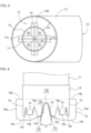
FIG. 3 is a plan view of the vicinity of an outlet of a first exhaust pipe, an inlet of a second exhaust pipe, and a partition. -
FIG. 4 is a side view of the vicinity of an outlet of a first exhaust pipe and a partition. -
FIG. 5 is a bottom view of the vicinity of an outlet of a first exhaust pipe and a partition. -
FIG. 6 is a schematic diagram illustrating divided regions. -
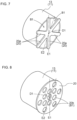
FIG. 7 is a perspective view of the vicinity of an outlet of a first exhaust pipe and partition in a further embodiment of the present invention. -
FIG. 8 is a perspective view of the vicinity of an outlet of a first exhaust pipe and partition in a further embodiment of the present invention. -
FIG. 9 is a perspective view of the vicinity of an outlet of a first exhaust pipe and notch part in a further embodiment of the present invention. -
FIGS. 1 to 9 illustrate a tractor that is an example of a work vehicle, wherein F shows a forward direction, B shows a backward direction, U shows an upward direction, and D shows a downward direction. - As illustrated in
FIG. 1 , amechanical body 3 is supported by right and leftfront wheels 1 and right and leftrear wheels 2. A diesel-type engine 4 is provided at a front portion of themechanical body 3, adriving unit 5 is provided at back portion of themechanical body 3, and a driver'sseat 6 and asteering wheel 7 for thefront wheels 1 are provided in thedriving unit 5. An arch-shapedROPS frame 8 is provided between theengine 4 and thedriving unit 5. - As illustrated in
FIGS. 1 and2 , exhaust of theengine 4 is fed to an exhaust purification device (not illustrated) (DPF) to remove particulates from the exhaust of theengine 4. Next, the exhaust of theengine 4 is fed from the exhaust purification device (DPF) to an exhaust purification device 9 (SCR), and nitrogen oxide is removed from the exhaust of theengine 4. - The
exhaust purification device 9 is disposed along the horizontal or left-right direction between theengine 4 and the driving unit 5 (steering wheel 7), and a round pipe shapedexhaust pipe 10 is extended downward from a right portion of theengine purification device 9. A round pipe shapedfirst exhaust pipe 11 is connected to theexhaust pipe 10 and extended downward, and a round pipe shapedsecond exhaust pipe 12 is supported along the vertical or up-down direction on the bottom of thefirst exhaust pipe 11. - With the above configuration, the exhaust of the
engine 4 is fed from the exhaust purification device (not illustrated) (DPF) to the exhaust purification device 9 (SCR) and sent from theexhaust pipe 10 to thefirst exhaust pipe 11, sent from anoutlet 13 of a lower portion of thefirst exhaust pipe 11 to aninlet 14 of an upper portion of thesecond exhaust pipe 12 and discharged from anoutlet 15 of a lower portion of thesecond exhaust pipe 12 . - As illustrated in
FIGS. 4 and5 , fourtriangular notch parts 18 are formed at intervals of 90 degrees on a peripheral part of theoutlet 13 of thefirst exhaust pipe 11. - At the peripheral part of the
outlet 13 of thefirst exhaust pipe 11, twotriangular notch parts 19 smaller than thenotch parts 18 are formed on each of the four portions between theadjacent notch parts 18, forming a total of eightnotch parts 19. A plurality ofnotch parts 19 are thereby formed across the entire periphery of the peripheral port of theoutlet 13 of thefirst exhaust pipe 11. - The
notch parts outlet 13 of thefirst exhaust pipe 11 seen from the direction A1 of the flow of exhaust discharged from theoutlet 13 of the first exhaust pipe 11 (seeFIG. 2 ). - As illustrated in
FIGS. 5 and 6 , when imagining virtual straight lines E1, E2, E3, E4 passing through the center D1 of theoutlet 13 of thefirst exhaust pipe 11 seen from the direction A1 of the flow of exhaust discharged from theoutlet 13 of the first exhaust pipe 11 (seeFIG. 2 ), thenotch parts 19 are formed with line symmetry with respect to virtual straight lines E1, E2, E3, E4. -
Notch parts end parts outlet 13 of the first exhaust pipe 11 (opposite side of the second exhaust pipe 12). Regardingend parts outlet 13 of thefirst exhaust pipe 11, theend part 13a adjacent to thenotch parts 18 extends farther downward (to thesecond exhaust pipe 12 side) than theend part 13b betweennotch parts 19. - As illustrated in
FIGS. 3, 4 , and5 , a plate material is folded into a triangular cross-section to formpartitions partitions partitions notch parts 18 of theoutlet 13 of thefirst exhaust pipe 11 and attached to theoutlet 13 of thefirst exhaust pipe 11. - Seen from the direction A1 of the flow of exhaust discharged from the
outlet 13 of the first exhaust pipe 11 (seeFIG. 2 ), the orthogonally crossing portions of thepartitions outlet 13 of thefirst exhaust pipe 11. Seen from the direction A1 of the flow of exhaust discharged from theoutlet 13 of thefirst exhaust pipe 11, thepartitions outlet 13 of thefirst exhaust pipe 11. - Due to the
partitions FIG. 2 ) of the flow of exhaust discharged from theoutlet 13 of the first exhaust pipe 11 (seeFIG. 4 ), the cross-sectional shape of thepartitions outlet 13 of thefirst exhaust pipe 11. - The
partitions outlet 13 of thefirst exhaust pipe 11 seen from the direction A1 of the flow of exhaust discharged from theoutlet 13 of the first exhaust pipe 11 (seeFIG. 2 ). - As illustrated in
FIGS. 5 and 6 , when imagining virtual straight lines E1, E2, E3, E4 passing through the center D1 of theoutlet 13 of thefirst exhaust pipe 11 seen from the direction A1 of the flow of exhaust discharged from theoutlet 13 of the first exhaust pipe 11 (seeFIG. 2 ), thepartitions - Even in a configuration in which the
partitions notch part 19 are combined, the configuration in which thepartitions notch part 19 are combined is formed with line symmetry with respect to the virtual straight lines E1, E2, E3, E4. - Outer ends 16a, 17a of the
partitions outlet 13 of thefirst exhaust pipe 11. Theupper end parts partitions upper end part 19a of the notch part 19 (opposite side of the second exhaust pipe 12) (seeFIG. 4 ), and thelower end parts partitions end parts outlet 13 of the first exhaust pipe 11 (to thesecond exhaust pipe 12 side) (seeFIG. 4 ). - Thus, the
partitions second exhaust pipe 12 than theend part 19a of the opposite side of thesecond exhaust pipe 12 of thenotch part 19, and theend part 13a of theoutlet 13 of thefirst exhaust pipe 11, and thepartitions end parts outlet 13 of thefirst exhaust pipe 11 towards thesecond exhaust pipe 12 side. - As illustrated in
FIGS. 5 and 6 , seen from the direction A1 of the flow of exhaust discharged from theoutlet 13 of the first exhaust pipe 11 (seeFIG. 2 ), the region of theoutlet 13 of thefirst exhaust pipe 11 is divided by thepartitions notch part 19 is also included in the four divided regions B1, and the adjacent divided regions B1 are partitioned by thepartitions partitions - Thus, seen from the direction A1 (see
FIG. 2 ) of the flow of exhaust discharged from theoutlet 13 of thefirst exhaust pipe 11, the areas of the four divided regions B1 are all the same. - When exhaust of the
engine 4 is sent to thefirst exhaust pipe 11, the exhaust of theengine 4 is divided into four flows corresponding to the divided regions B1 at theoutlet 13 of thefirst exhaust pipe 11 while passing through the divided regions B1 due to thepartitions partitions engine 4 become independent flows, and after this, the four flows of exhaust of theengine 4 are mixed with outside air and then converge. - At the same time, the cross-sectional shape of the
partitions outlet 13 of thefirst exhaust pipe 11, and thus, the region of theoutlet 13 of thefirst exhaust pipe 11 is narrowed by thepartitions engine 4 is obstructed by thepartition engine 4 to increase. A negative pressure space in which exhaust of theengine 4 cannot flow is more easily generated in the region downstream of thepartitions - In the flow corresponding to the divided regions B1 of the exhaust of the
engine 4, the boundary surface, which is the portions at which the flow of exhaust of theengine 4 contacts outside air, is the sum of a portion L1 corresponding to thelower end part 16c of thepartition 16, a portion L2 corresponding to thelower end part 17c of thepartition 17, two portions L3 corresponding to the peripheral parts of the twonotch parts 19, and three portions L4 corresponding to endparts outlet 13 of thefirst exhaust pipe 11. - Thus, the boundary surface when the
partitions notch parts 19 are provided is the sum of the boundary surfaces of the four flows corresponding to the divided regions B1 of the exhaust of theengine 4. - As illustrated in
FIG. 3 , thesecond exhaust pipe 12 is formed to have a larger diameter than thefirst exhaust pipe 11, and theinlet 14 of thesecond exhaust pipe 12 is formed to have a larger outer diameter than theoutlet 13 of thefirst exhaust pipe 11. Theoutlet 15 of thesecond exhaust pipe 12 is formed so as to face laterally outward to the right from themechanical body 3. - As illustrated in
FIG. 2 , in a side view (direction orthogonal to the direction A1 of the flow exhaust discharged from theoutlet 13 of the first exhaust pipe 11), theoutlet 13 of thefirst exhaust pipe 11 and theinlet 14 of thesecond exhaust pipe 12 are disposed in proximity such that the outlet of the first exhaust pipe 11 (endparts partitions 16, 17) and theoutlet 14 of thesecond exhaust pipe 12 are disposed at small intervals C2. - As illustrated in
FIG. 3 , seen from the direction A1 of the flow of exhaust discharged from theoutlet 13 of the first exhaust pipe 11 (seeFIG. 2 ), theoutlet 13 of thefirst exhaust pipe 11 and thepartitions inlet 14 of thesecond exhaust pipe 12. - The peripheral part of the
outlet 13 of thefirst exhaust pipe 11 and the peripheral part of theinlet 14 of thesecond exhaust pipe 12 are disposed at intervals C3. Theouter end parts partitions inlet 14 of thesecond exhaust pipe 12 are disposed at intervals C4 narrower than the intervals C3. - With the above configuration, the exhaust of the
engine 4 is discharged from theoutlet 13 of thefirst exhaust pipe 11, is sent to theinlet 14 of thesecond exhaust pipe 12, enters the interior of thesecond exhaust pipe 12, and is exhausted from theoutlet 15 of the lower portion of thesecond exhaust pipe 12. - As described above (relationship between the partitions and notch parts and the outlet of the first exhaust pipe), by providing the
partitions parts 19, the flow speed of exhaust of theengine 4 can be appropriately increased. - A negative pressure space in which exhaust of the
engine 4 cannot flow is more easily generated in the region downstream of thepartitions - The boundary surface when the
partitions notch parts 19 are provided is the sum of the boundary surfaces of the four flows corresponding to the divided regions B1 of the exhaust of theengine 4. - Thus, a large amount of outside air is drawn into the flow of exhaust of the
engine 4, brought into the interior of thesecond exhaust pipe 12 from between the peripheral part of theoutlet 13 of thefirst exhaust pipe 11 and theinlet 14 of thesecond exhaust pipe 12, mixed into the exhaust of theengine 4, and the temperature of the exhaust of theengine 4 is lowered. - In the configuration illustrated in
FIGS. 2 to 5 , thenotch part 19 may be removed. - In a side view, in order to overlap the
outlet 13 of thefirst exhaust pipe 11 and theinlet 14 of thesecond exhaust pipe 12, theoutlet 13 of thefirst exhaust pipe 11 may be disposed along the direction A1 (seeFIG. 2 ) of the flow of exhaust discharged from theoutlet 13 of thefirst exhaust pipe 11 so as to slightly enter the interior of theinlet 14 of thesecond exhaust pipe 12. -
Partitions inlet 14 of thesecond exhaust pipe 12 and theoutlet 13 of thefirst exhaust pipe 11 may be disposed in proximity to thepartitions - The invention may also configure the work vehicle so that the
partitions partitions outlet 13 of thefirst exhaust pipe 11 seen from the direction A1 (seeFIG. 2 ) of the flow of exhaust discharged from theoutlet 13 of thefirst exhaust pipe 11. - The cross-sectional shape of the
partitions - According to this configuration, the outer surfaces of the
partitions engine 4 along the outer surfaces of thepartitions - As illustrated in
FIG. 7 , apartition 20 may be configured by a flat-shaped member or a flat plate and thepartition 20 formed so that a plurality ofarm portions 20a extend radially outward from the center of theoutlet 13 of thefirst exhaust pipe 11 form the center of thepartition 20. - In the configuration illustrated in
FIG. 7 , thearm portions 20a of thepartition 20 are disposed with point symmetry with respect to the center D1 of theoutlet 13 of thefirst exhaust pipe 11 seen from the direction A1 of the flow of exhaust discharged from theoutlet 13 of the first exhaust pipe 11 (seeFIG. 2 ). - When imagining virtual straight lines E1, E2 passing through the center D1 of the
outlet 13 of thefirst exhaust pipe 11 seen from the direction A1 of the flow of exhaust discharged from theoutlet 13 of the first exhaust pipe 11 (seeFIG. 2 ), thepartition 20 is formed with line symmetry with respect to virtual straight lines E1, E2. The virtual straight line E1 may be imagined so that it passes through adifferent arm portion 20a than thearm portion 20a illustrated inFIG. 7 of thepartition 20. The virtual straight line E2 may be imagined so that it passes through a different gap ofarm portions 20a than the gap ofarm portions 20a illustrated inFIG. 7 of thepartition 20. - One divided region B1 is formed by two
adjacent arm portions 20a of thepartition 20 and the peripheral part of theoutlet 13 of thefirst exhaust pipe 11. By setting the angles betweenadjacent arm portions 20a of thepartition 20 to be all the same, the areas of the plurality of divided regions B1 are made all the same. - In this case, the number of
arm portions 20a of thepartition 20 is assumed to be 3, 4, 5, and various other numbers. The angles betweenadjacent arm portions 20a of thepartition 20 may be set to be different from each other, to configure so that the areas of the plurality of divided regions B1 are not all the same. In addition to thepartition 20, anotch part 19 illustrated inFIGS. 4 and5 may be formed on theoutlet 13 of thefirst exhaust pipe 11. - As illustrated in
FIG. 8 , thepartition 20 may be configured by a flat-shaped member or a flat plate, and a plurality ofcircular openings 20b of the same inner diameter opened to form thepartition 20. - One divided region B1 is formed by one
opening 20b of thepartition 20. Because theopenings 20b of thepartition 20 have the same inner diameter, the areas of the plurality of divided regions B1 are all the same. - In the configuration illustrated in
FIG. 8 , theopenings 20b of thepartition 20 are disposed with point symmetry with respect to the center D1 of theoutlet 13 of thefirst exhaust pipe 11 seen from the direction A1 of the flow of exhaust discharged from theoutlet 13 of the first exhaust pipe 11 (seeFIG. 2 ). - When imagining virtual straight lines E1, E2 passing through the center D1 of the
outlet 13 of thefirst exhaust pipe 11 seen from the direction A1 of the flow of exhaust discharged from theoutlet 13 of the first exhaust pipe 11 (seeFIG. 2 ), thepartition 20 is formed with line symmetry with respect to virtual straight lines E1, E2. The virtual straight line E1 may be imagined so that it passes through a differentinside opening 20b than theinside opening 20b illustrated inFIG. 8 of thepartition 20. The virtual straight line E2 may be imagined so that it passes through a differentoutside opening 20b than theoutside opening 20b illustrated inFIG. 8 of thepartition 20. - In this case, the inner diameters of the plurality of
opening 20b of thepartition 20 may be set to be different from each other to configure so that the areas of the plurality of divided regions B1 are not all the same. - As illustrated in
FIG. 9 , thepartitions notch parts 19 across the entire periphery of the peripheral portion of theoutlet 13 of thefirst exhaust pipe 11. - In the plurality of
notch parts 19, instead of forming all thenotch parts 19 at the same size, thenotch parts 19 may be configured so that a mixture of different sizes are present, such aslarge notch parts 19 andsmall notch parts 19. - In the configuration illustrated in
FIG. 9 , thenotch parts 19 are formed with point symmetry with respect to the center D1 (seeFIGS. 7 and 8 ) of theoutlet 13 of thefirst exhaust pipe 11 seen from the direction A1 of the flow of exhaust discharged from theoutlet 13 of the first exhaust pipe 11 (seeFIG. 2 ). - When imagining virtual straight lines E1, E2 passing through the center D1 of the
outlet 13 of thefirst exhaust pipe 11 seen from the direction A1 of the flow of exhaust discharged from theoutlet 13 of the first exhaust pipe 11 (seeFIG. 2 ), thenotch parts 19 are formed with line symmetry with respect to virtual straight lines E1, E2. - The virtual straight line E1 may be imagined to that it passes through an end part of the
second exhaust pipe 12 side of adifferent notch part 19 than thenotch part 19 illustrated inFIG. 9 . The virtual straight line E2 may be imagined to that it passes through the center part of adifferent notch part 19 than thenotch part 19 illustrated inFIG. 9 . - Instead of
triangular notch parts 19,notch parts 19 of various shapes such as U-shaped, rectangular, and semicircular may be formed, and a mixture ofnotch parts 19 with different shapes may be configured. - The present invention may be applied not only to tractors but also to agricultural work vehicles such as combine harvesters and ridden rice planters, construction work vehicles such as backhoes and wheel loaders, and work vehicles for transporting materials and the like.
Claims (9)
- A work vehicle comprising:a first exhaust pipe (11) for engine exhaust; anda second exhaust pipe (12) provided with an inlet (14) having an outer diameter larger than an outlet diameter of an outlet (13) of the first exhaust pipe (11), whereinthe outlet (13) of the first exhaust pipe (11) and the inlet (14) of the second exhaust pipe (12) are disposed in proximity such that the outlet (13) of the first exhaust pipe (11) is disposed inside the inlet (14) of the second exhaust pipe (12), andthe work vehicle further comprises a partition (16, 17) dividing a cross-section of the outlet (13) of the first exhaust pipe (11) into a plurality of divided regions when viewed from an exhaust flow direction and partitioning the adjacent divided regions at intervals, wherein a cross-section of the partition (16, 17) has a wedge shape tapering toward an upstream of the exhaust discharged from the outlet (13) of the first exhaust pipe (11).
- The work vehicle according to claim 1, wherein the partition (16, 17) is attached to the outlet (13) of the first exhaust pipe (11).
- The work vehicle according to claim 1 or claim 2, wherein areas of the plurality of divided regions are all the same when viewed from the exhaust flow direction.
- The work vehicle according to any one of claims 1 to 3, wherein the partition (16, 17)extends radially outward from a center of the outlet (13) of the first exhaust pipe (11) when viewed from the exhaust flow direction.
- The work vehicle according to any one of claims 1 to 3, further comprising a further partition (20), the further partition (20) being a flat-shaped member having a plurality of openings (20b).
- The work vehicle according to any one of claims 1 to 5, wherein the partition (16, 17) is line symmetrical with respect to a virtual straight line passing through a center of the outlet (13) of the first exhaust pipe (11) when viewed from the exhaust flow direction.
- The work vehicle according to claim 1wherein
the work vehicle further comprises one or more notch parts (19) extending from an end (13a, 13b) of the outlet (13) of the first exhaust pipe (11) to a direction opposite to the second exhaust pipe (12) and formed on a peripheral part of the outlet (13) of the first exhaust pipe (11). - The work vehicle according to claim 7, whereinthe partition (16, 17) is attached on the first exhaust pipe (11) across a portion of the first exhaust pipe (11) further separated to a direction opposite to the second exhaust pipe (12) than the end of the one or more notch parts (19) in the opposite direction, and the end of the outlet (13) of the first exhaust pipe (11), andthe partition (16, 17) protrudes from the end of the outlet (13) of the first exhaust pipe (11) toward the second exhaust pipe (12).
- The work vehicle according to claim 7 or claim 8, wherein the partition (16, 17) and the one or more notch parts (19) are line symmetrical with respect to a virtual straight line passing through a center of the outlet (13) of the first exhaust pipe (11) when viewed from the exhaust flow direction.
Priority Applications (1)
| Application Number | Priority Date | Filing Date | Title |
|---|---|---|---|
| EP22203935.6A EP4361410B1 (en) | 2022-10-26 | 2022-10-26 | Work vehicle |
Applications Claiming Priority (1)
| Application Number | Priority Date | Filing Date | Title |
|---|---|---|---|
| EP22203935.6A EP4361410B1 (en) | 2022-10-26 | 2022-10-26 | Work vehicle |
Publications (2)
| Publication Number | Publication Date |
|---|---|
| EP4361410A1 EP4361410A1 (en) | 2024-05-01 |
| EP4361410B1 true EP4361410B1 (en) | 2025-02-12 |
Family
ID=84688314
Family Applications (1)
| Application Number | Title | Priority Date | Filing Date |
|---|---|---|---|
| EP22203935.6A Active EP4361410B1 (en) | 2022-10-26 | 2022-10-26 | Work vehicle |
Country Status (1)
| Country | Link |
|---|---|
| EP (1) | EP4361410B1 (en) |
Family Cites Families (7)
| Publication number | Priority date | Publication date | Assignee | Title |
|---|---|---|---|---|
| DE102009046253A1 (en) * | 2009-10-30 | 2011-05-05 | Deere & Company, Moline | Device for cooling an exhaust gas flow |
| US20120145268A1 (en) * | 2010-12-08 | 2012-06-14 | Caterpillar Inc. | Exhaust Ejector For An Internal Combustion Engine |
| DE102011014908A1 (en) * | 2011-03-24 | 2011-11-10 | Daimler Ag | Tail pipe arrangement for exhaust system of vehicle, comprises inlet, by which surrounding air is introduced into exhaust flow for cooling exhaust flow |
| US20140020638A1 (en) * | 2011-04-07 | 2014-01-23 | Volvo Construction Equipment Ab | Exhaust gas temperature reduction device for an engine of construction equipment |
| JP5911758B2 (en) | 2011-07-29 | 2016-04-27 | 株式会社クボタ | Work vehicle exhaust system |
| US8720195B2 (en) * | 2012-02-14 | 2014-05-13 | Deere & Company | Exhaust assembly |
| JP7507681B2 (en) * | 2020-12-25 | 2024-06-28 | 株式会社クボタ | Exhaust gas diffusion device |
-
2022
- 2022-10-26 EP EP22203935.6A patent/EP4361410B1/en active Active
Also Published As
| Publication number | Publication date |
|---|---|
| EP4361410A1 (en) | 2024-05-01 |
Similar Documents
| Publication | Publication Date | Title |
|---|---|---|
| CN107178406B (en) | Mixer | |
| US9464546B2 (en) | Assembly for purifying exhaust gases | |
| US10408110B2 (en) | Reductant decomposition reactor chamber | |
| JP5905997B2 (en) | Work vehicle | |
| CA2763018C (en) | Catalytic converter module | |
| DE102016222743A1 (en) | Integrated exhaust aftertreatment system | |
| KR102018390B1 (en) | Combine | |
| CN103184917B (en) | Waste gas treatment equipment | |
| US20230016427A1 (en) | Body mixing decomposition reactor | |
| CN107435576A (en) | Integrated exhaust gas aftertreatment system | |
| CN212054866U (en) | Tail gas aftertreatment system | |
| US9488091B2 (en) | Exhaust pipe structure with catalyst for engine | |
| JP5865197B2 (en) | Exhaust pipe | |
| WO2013112170A1 (en) | Cross style (4 port) ammonia gas injector | |
| WO2013154573A1 (en) | Mixing plate as stabilizer for ammonia gas injector | |
| EP4361410A1 (en) | Work vehicle | |
| US11946402B2 (en) | Work vehicle | |
| JP2022102298A (en) | Exhaust gas diffusion device | |
| US20210270170A1 (en) | Outlet flow mixers for selective catalytic reduction systems of work vehicles | |
| EP4170140B1 (en) | Exhaust treatment system for work vehicles and related flow mixers | |
| US9174167B2 (en) | Mixing plate providing reductant distribution | |
| CN119801708A (en) | Exhaust mixer assembly | |
| JP7142505B2 (en) | work vehicle | |
| AU2017367585B2 (en) | Inlet diffuser for exhaust aftertreatment system | |
| US20260102746A1 (en) | Exhaust treatment device |
Legal Events
| Date | Code | Title | Description |
|---|---|---|---|
| PUAI | Public reference made under article 153(3) epc to a published international application that has entered the european phase |
Free format text: ORIGINAL CODE: 0009012 |
|
| STAA | Information on the status of an ep patent application or granted ep patent |
Free format text: STATUS: THE APPLICATION HAS BEEN PUBLISHED |
|
| AK | Designated contracting states |
Kind code of ref document: A1 Designated state(s): AL AT BE BG CH CY CZ DE DK EE ES FI FR GB GR HR HU IE IS IT LI LT LU LV MC ME MK MT NL NO PL PT RO RS SE SI SK SM TR |
|
| STAA | Information on the status of an ep patent application or granted ep patent |
Free format text: STATUS: REQUEST FOR EXAMINATION WAS MADE |
|
| 17P | Request for examination filed |
Effective date: 20240618 |
|
| RBV | Designated contracting states (corrected) |
Designated state(s): AL AT BE BG CH CY CZ DE DK EE ES FI FR GB GR HR HU IE IS IT LI LT LU LV MC ME MK MT NL NO PL PT RO RS SE SI SK SM TR |
|
| GRAP | Despatch of communication of intention to grant a patent |
Free format text: ORIGINAL CODE: EPIDOSNIGR1 |
|
| STAA | Information on the status of an ep patent application or granted ep patent |
Free format text: STATUS: GRANT OF PATENT IS INTENDED |
|
| INTG | Intention to grant announced |
Effective date: 20240927 |
|
| GRAS | Grant fee paid |
Free format text: ORIGINAL CODE: EPIDOSNIGR3 |
|
| GRAA | (expected) grant |
Free format text: ORIGINAL CODE: 0009210 |
|
| STAA | Information on the status of an ep patent application or granted ep patent |
Free format text: STATUS: THE PATENT HAS BEEN GRANTED |
|
| AK | Designated contracting states |
Kind code of ref document: B1 Designated state(s): AL AT BE BG CH CY CZ DE DK EE ES FI FR GB GR HR HU IE IS IT LI LT LU LV MC ME MK MT NL NO PL PT RO RS SE SI SK SM TR |
|
| REG | Reference to a national code |
Ref country code: GB Ref legal event code: FG4D |
|
| REG | Reference to a national code |
Ref country code: CH Ref legal event code: EP |
|
| REG | Reference to a national code |
Ref country code: DE Ref legal event code: R096 Ref document number: 602022010442 Country of ref document: DE |
|
| REG | Reference to a national code |
Ref country code: IE Ref legal event code: FG4D |
|
| REG | Reference to a national code |
Ref country code: NL Ref legal event code: MP Effective date: 20250212 |
|
| PG25 | Lapsed in a contracting state [announced via postgrant information from national office to epo] |
Ref country code: RS Free format text: LAPSE BECAUSE OF FAILURE TO SUBMIT A TRANSLATION OF THE DESCRIPTION OR TO PAY THE FEE WITHIN THE PRESCRIBED TIME-LIMIT Effective date: 20250512 |
|
| PG25 | Lapsed in a contracting state [announced via postgrant information from national office to epo] |
Ref country code: FI Free format text: LAPSE BECAUSE OF FAILURE TO SUBMIT A TRANSLATION OF THE DESCRIPTION OR TO PAY THE FEE WITHIN THE PRESCRIBED TIME-LIMIT Effective date: 20250212 |
|
| PG25 | Lapsed in a contracting state [announced via postgrant information from national office to epo] |
Ref country code: PL Free format text: LAPSE BECAUSE OF FAILURE TO SUBMIT A TRANSLATION OF THE DESCRIPTION OR TO PAY THE FEE WITHIN THE PRESCRIBED TIME-LIMIT Effective date: 20250212 |
|
| PG25 | Lapsed in a contracting state [announced via postgrant information from national office to epo] |
Ref country code: ES Free format text: LAPSE BECAUSE OF FAILURE TO SUBMIT A TRANSLATION OF THE DESCRIPTION OR TO PAY THE FEE WITHIN THE PRESCRIBED TIME-LIMIT Effective date: 20250212 |
|
| REG | Reference to a national code |
Ref country code: LT Ref legal event code: MG9D |
|
| PG25 | Lapsed in a contracting state [announced via postgrant information from national office to epo] |
Ref country code: IS Free format text: LAPSE BECAUSE OF FAILURE TO SUBMIT A TRANSLATION OF THE DESCRIPTION OR TO PAY THE FEE WITHIN THE PRESCRIBED TIME-LIMIT Effective date: 20250612 Ref country code: NO Free format text: LAPSE BECAUSE OF FAILURE TO SUBMIT A TRANSLATION OF THE DESCRIPTION OR TO PAY THE FEE WITHIN THE PRESCRIBED TIME-LIMIT Effective date: 20250512 |
|
| PG25 | Lapsed in a contracting state [announced via postgrant information from national office to epo] |
Ref country code: NL Free format text: LAPSE BECAUSE OF FAILURE TO SUBMIT A TRANSLATION OF THE DESCRIPTION OR TO PAY THE FEE WITHIN THE PRESCRIBED TIME-LIMIT Effective date: 20250212 |
|
| PG25 | Lapsed in a contracting state [announced via postgrant information from national office to epo] |
Ref country code: HR Free format text: LAPSE BECAUSE OF FAILURE TO SUBMIT A TRANSLATION OF THE DESCRIPTION OR TO PAY THE FEE WITHIN THE PRESCRIBED TIME-LIMIT Effective date: 20250212 |
|
| PG25 | Lapsed in a contracting state [announced via postgrant information from national office to epo] |
Ref country code: LV Free format text: LAPSE BECAUSE OF FAILURE TO SUBMIT A TRANSLATION OF THE DESCRIPTION OR TO PAY THE FEE WITHIN THE PRESCRIBED TIME-LIMIT Effective date: 20250212 Ref country code: PT Free format text: LAPSE BECAUSE OF FAILURE TO SUBMIT A TRANSLATION OF THE DESCRIPTION OR TO PAY THE FEE WITHIN THE PRESCRIBED TIME-LIMIT Effective date: 20250612 |
|
| PG25 | Lapsed in a contracting state [announced via postgrant information from national office to epo] |
Ref country code: GR Free format text: LAPSE BECAUSE OF FAILURE TO SUBMIT A TRANSLATION OF THE DESCRIPTION OR TO PAY THE FEE WITHIN THE PRESCRIBED TIME-LIMIT Effective date: 20250513 Ref country code: BG Free format text: LAPSE BECAUSE OF FAILURE TO SUBMIT A TRANSLATION OF THE DESCRIPTION OR TO PAY THE FEE WITHIN THE PRESCRIBED TIME-LIMIT Effective date: 20250212 |
|
| PG25 | Lapsed in a contracting state [announced via postgrant information from national office to epo] |
Ref country code: SE Free format text: LAPSE BECAUSE OF FAILURE TO SUBMIT A TRANSLATION OF THE DESCRIPTION OR TO PAY THE FEE WITHIN THE PRESCRIBED TIME-LIMIT Effective date: 20250212 |
|
| PG25 | Lapsed in a contracting state [announced via postgrant information from national office to epo] |
Ref country code: SM Free format text: LAPSE BECAUSE OF FAILURE TO SUBMIT A TRANSLATION OF THE DESCRIPTION OR TO PAY THE FEE WITHIN THE PRESCRIBED TIME-LIMIT Effective date: 20250212 |
|
| PG25 | Lapsed in a contracting state [announced via postgrant information from national office to epo] |
Ref country code: DK Free format text: LAPSE BECAUSE OF FAILURE TO SUBMIT A TRANSLATION OF THE DESCRIPTION OR TO PAY THE FEE WITHIN THE PRESCRIBED TIME-LIMIT Effective date: 20250212 |
|
| PG25 | Lapsed in a contracting state [announced via postgrant information from national office to epo] |
Ref country code: IT Free format text: LAPSE BECAUSE OF FAILURE TO SUBMIT A TRANSLATION OF THE DESCRIPTION OR TO PAY THE FEE WITHIN THE PRESCRIBED TIME-LIMIT Effective date: 20250212 |
|
| PG25 | Lapsed in a contracting state [announced via postgrant information from national office to epo] |
Ref country code: AT Free format text: LAPSE BECAUSE OF FAILURE TO SUBMIT A TRANSLATION OF THE DESCRIPTION OR TO PAY THE FEE WITHIN THE PRESCRIBED TIME-LIMIT Effective date: 20250212 |
|
| PG25 | Lapsed in a contracting state [announced via postgrant information from national office to epo] |
Ref country code: EE Free format text: LAPSE BECAUSE OF FAILURE TO SUBMIT A TRANSLATION OF THE DESCRIPTION OR TO PAY THE FEE WITHIN THE PRESCRIBED TIME-LIMIT Effective date: 20250212 Ref country code: CZ Free format text: LAPSE BECAUSE OF FAILURE TO SUBMIT A TRANSLATION OF THE DESCRIPTION OR TO PAY THE FEE WITHIN THE PRESCRIBED TIME-LIMIT Effective date: 20250212 |
|
| PG25 | Lapsed in a contracting state [announced via postgrant information from national office to epo] |
Ref country code: RO Free format text: LAPSE BECAUSE OF FAILURE TO SUBMIT A TRANSLATION OF THE DESCRIPTION OR TO PAY THE FEE WITHIN THE PRESCRIBED TIME-LIMIT Effective date: 20250212 |
|
| PG25 | Lapsed in a contracting state [announced via postgrant information from national office to epo] |
Ref country code: SK Free format text: LAPSE BECAUSE OF FAILURE TO SUBMIT A TRANSLATION OF THE DESCRIPTION OR TO PAY THE FEE WITHIN THE PRESCRIBED TIME-LIMIT Effective date: 20250212 |
|
| REG | Reference to a national code |
Ref country code: DE Ref legal event code: R097 Ref document number: 602022010442 Country of ref document: DE |
|
| PLBE | No opposition filed within time limit |
Free format text: ORIGINAL CODE: 0009261 |
|
| STAA | Information on the status of an ep patent application or granted ep patent |
Free format text: STATUS: NO OPPOSITION FILED WITHIN TIME LIMIT |
|
| PGFP | Annual fee paid to national office [announced via postgrant information from national office to epo] |
Ref country code: DE Payment date: 20251029 Year of fee payment: 4 |
|
| PGFP | Annual fee paid to national office [announced via postgrant information from national office to epo] |
Ref country code: FR Payment date: 20251027 Year of fee payment: 4 |
|
| 26N | No opposition filed |
Effective date: 20251113 |