EP4361402A1 - Rotor assemblies - Google Patents
Rotor assemblies Download PDFInfo
- Publication number
- EP4361402A1 EP4361402A1 EP23206768.6A EP23206768A EP4361402A1 EP 4361402 A1 EP4361402 A1 EP 4361402A1 EP 23206768 A EP23206768 A EP 23206768A EP 4361402 A1 EP4361402 A1 EP 4361402A1
- Authority
- EP
- European Patent Office
- Prior art keywords
- root
- rotor
- spacer
- blade
- slot
- Prior art date
- Legal status (The legal status is an assumption and is not a legal conclusion. Google has not performed a legal analysis and makes no representation as to the accuracy of the status listed.)
- Pending
Links
- 230000000712 assembly Effects 0.000 title 1
- 238000000429 assembly Methods 0.000 title 1
- 125000006850 spacer group Chemical group 0.000 claims abstract description 107
- 210000004027 cell Anatomy 0.000 claims abstract description 36
- 210000003850 cellular structure Anatomy 0.000 claims abstract description 27
- 230000001413 cellular effect Effects 0.000 claims description 38
- 239000011148 porous material Substances 0.000 claims description 11
- 239000000463 material Substances 0.000 description 11
- 238000011144 upstream manufacturing Methods 0.000 description 8
- 238000002485 combustion reaction Methods 0.000 description 3
- 230000007423 decrease Effects 0.000 description 3
- 239000000446 fuel Substances 0.000 description 2
- 238000004519 manufacturing process Methods 0.000 description 2
- 239000000203 mixture Substances 0.000 description 2
- 239000007787 solid Substances 0.000 description 2
- 239000010936 titanium Substances 0.000 description 2
- 229920002430 Fibre-reinforced plastic Polymers 0.000 description 1
- RTAQQCXQSZGOHL-UHFFFAOYSA-N Titanium Chemical compound [Ti] RTAQQCXQSZGOHL-UHFFFAOYSA-N 0.000 description 1
- 239000000654 additive Substances 0.000 description 1
- 230000000996 additive effect Effects 0.000 description 1
- 239000000956 alloy Substances 0.000 description 1
- 229910045601 alloy Inorganic materials 0.000 description 1
- 229910052782 aluminium Inorganic materials 0.000 description 1
- XAGFODPZIPBFFR-UHFFFAOYSA-N aluminium Chemical compound [Al] XAGFODPZIPBFFR-UHFFFAOYSA-N 0.000 description 1
- 238000005452 bending Methods 0.000 description 1
- 238000005266 casting Methods 0.000 description 1
- 239000002131 composite material Substances 0.000 description 1
- 230000006835 compression Effects 0.000 description 1
- 238000007906 compression Methods 0.000 description 1
- 239000011151 fibre-reinforced plastic Substances 0.000 description 1
- 239000006260 foam Substances 0.000 description 1
- 229910052751 metal Inorganic materials 0.000 description 1
- 239000002184 metal Substances 0.000 description 1
- 238000000034 method Methods 0.000 description 1
- NJPPVKZQTLUDBO-UHFFFAOYSA-N novaluron Chemical compound C1=C(Cl)C(OC(F)(F)C(OC(F)(F)F)F)=CC=C1NC(=O)NC(=O)C1=C(F)C=CC=C1F NJPPVKZQTLUDBO-UHFFFAOYSA-N 0.000 description 1
- 238000005096 rolling process Methods 0.000 description 1
- 238000010008 shearing Methods 0.000 description 1
- 229910052719 titanium Inorganic materials 0.000 description 1
Images


Classifications
-
- F—MECHANICAL ENGINEERING; LIGHTING; HEATING; WEAPONS; BLASTING
- F01—MACHINES OR ENGINES IN GENERAL; ENGINE PLANTS IN GENERAL; STEAM ENGINES
- F01D—NON-POSITIVE DISPLACEMENT MACHINES OR ENGINES, e.g. STEAM TURBINES
- F01D5/00—Blades; Blade-carrying members; Heating, heat-insulating, cooling or antivibration means on the blades or the members
- F01D5/30—Fixing blades to rotors; Blade roots ; Blade spacers
-
- F—MECHANICAL ENGINEERING; LIGHTING; HEATING; WEAPONS; BLASTING
- F01—MACHINES OR ENGINES IN GENERAL; ENGINE PLANTS IN GENERAL; STEAM ENGINES
- F01D—NON-POSITIVE DISPLACEMENT MACHINES OR ENGINES, e.g. STEAM TURBINES
- F01D5/00—Blades; Blade-carrying members; Heating, heat-insulating, cooling or antivibration means on the blades or the members
- F01D5/30—Fixing blades to rotors; Blade roots ; Blade spacers
- F01D5/32—Locking, e.g. by final locking blades or keys
- F01D5/323—Locking of axial insertion type blades by means of a key or the like parallel to the axis of the rotor
-
- F—MECHANICAL ENGINEERING; LIGHTING; HEATING; WEAPONS; BLASTING
- F01—MACHINES OR ENGINES IN GENERAL; ENGINE PLANTS IN GENERAL; STEAM ENGINES
- F01D—NON-POSITIVE DISPLACEMENT MACHINES OR ENGINES, e.g. STEAM TURBINES
- F01D11/00—Preventing or minimising internal leakage of working-fluid, e.g. between stages
- F01D11/005—Sealing means between non relatively rotating elements
- F01D11/006—Sealing the gap between rotor blades or blades and rotor
- F01D11/008—Sealing the gap between rotor blades or blades and rotor by spacer elements between the blades, e.g. independent interblade platforms
-
- F—MECHANICAL ENGINEERING; LIGHTING; HEATING; WEAPONS; BLASTING
- F05—INDEXING SCHEMES RELATING TO ENGINES OR PUMPS IN VARIOUS SUBCLASSES OF CLASSES F01-F04
- F05D—INDEXING SCHEME FOR ASPECTS RELATING TO NON-POSITIVE-DISPLACEMENT MACHINES OR ENGINES, GAS-TURBINES OR JET-PROPULSION PLANTS
- F05D2220/00—Application
- F05D2220/30—Application in turbines
- F05D2220/32—Application in turbines in gas turbines
-
- F—MECHANICAL ENGINEERING; LIGHTING; HEATING; WEAPONS; BLASTING
- F05—INDEXING SCHEMES RELATING TO ENGINES OR PUMPS IN VARIOUS SUBCLASSES OF CLASSES F01-F04
- F05D—INDEXING SCHEME FOR ASPECTS RELATING TO NON-POSITIVE-DISPLACEMENT MACHINES OR ENGINES, GAS-TURBINES OR JET-PROPULSION PLANTS
- F05D2240/00—Components
- F05D2240/80—Platforms for stationary or moving blades
-
- F—MECHANICAL ENGINEERING; LIGHTING; HEATING; WEAPONS; BLASTING
- F05—INDEXING SCHEMES RELATING TO ENGINES OR PUMPS IN VARIOUS SUBCLASSES OF CLASSES F01-F04
- F05D—INDEXING SCHEME FOR ASPECTS RELATING TO NON-POSITIVE-DISPLACEMENT MACHINES OR ENGINES, GAS-TURBINES OR JET-PROPULSION PLANTS
- F05D2250/00—Geometry
- F05D2250/10—Two-dimensional
- F05D2250/18—Two-dimensional patterned
- F05D2250/183—Two-dimensional patterned zigzag
-
- F—MECHANICAL ENGINEERING; LIGHTING; HEATING; WEAPONS; BLASTING
- F05—INDEXING SCHEMES RELATING TO ENGINES OR PUMPS IN VARIOUS SUBCLASSES OF CLASSES F01-F04
- F05D—INDEXING SCHEME FOR ASPECTS RELATING TO NON-POSITIVE-DISPLACEMENT MACHINES OR ENGINES, GAS-TURBINES OR JET-PROPULSION PLANTS
- F05D2250/00—Geometry
- F05D2250/10—Two-dimensional
- F05D2250/18—Two-dimensional patterned
- F05D2250/184—Two-dimensional patterned sinusoidal
-
- F—MECHANICAL ENGINEERING; LIGHTING; HEATING; WEAPONS; BLASTING
- F05—INDEXING SCHEMES RELATING TO ENGINES OR PUMPS IN VARIOUS SUBCLASSES OF CLASSES F01-F04
- F05D—INDEXING SCHEME FOR ASPECTS RELATING TO NON-POSITIVE-DISPLACEMENT MACHINES OR ENGINES, GAS-TURBINES OR JET-PROPULSION PLANTS
- F05D2250/00—Geometry
- F05D2250/20—Three-dimensional
- F05D2250/28—Three-dimensional patterned
- F05D2250/283—Three-dimensional patterned honeycomb
-
- F—MECHANICAL ENGINEERING; LIGHTING; HEATING; WEAPONS; BLASTING
- F05—INDEXING SCHEMES RELATING TO ENGINES OR PUMPS IN VARIOUS SUBCLASSES OF CLASSES F01-F04
- F05D—INDEXING SCHEME FOR ASPECTS RELATING TO NON-POSITIVE-DISPLACEMENT MACHINES OR ENGINES, GAS-TURBINES OR JET-PROPULSION PLANTS
- F05D2250/00—Geometry
- F05D2250/70—Shape
-
- F—MECHANICAL ENGINEERING; LIGHTING; HEATING; WEAPONS; BLASTING
- F05—INDEXING SCHEMES RELATING TO ENGINES OR PUMPS IN VARIOUS SUBCLASSES OF CLASSES F01-F04
- F05D—INDEXING SCHEME FOR ASPECTS RELATING TO NON-POSITIVE-DISPLACEMENT MACHINES OR ENGINES, GAS-TURBINES OR JET-PROPULSION PLANTS
- F05D2300/00—Materials; Properties thereof
- F05D2300/50—Intrinsic material properties or characteristics
- F05D2300/514—Porosity
-
- F—MECHANICAL ENGINEERING; LIGHTING; HEATING; WEAPONS; BLASTING
- F05—INDEXING SCHEMES RELATING TO ENGINES OR PUMPS IN VARIOUS SUBCLASSES OF CLASSES F01-F04
- F05D—INDEXING SCHEME FOR ASPECTS RELATING TO NON-POSITIVE-DISPLACEMENT MACHINES OR ENGINES, GAS-TURBINES OR JET-PROPULSION PLANTS
- F05D2300/00—Materials; Properties thereof
- F05D2300/60—Properties or characteristics given to material by treatment or manufacturing
- F05D2300/612—Foam
Definitions
- This disclosure relates generally to a gas turbine engine and, more particularly, to a root spacer for arranging between a rotor disk and a root of a rotor blade.
- a fan rotor for a typical turbofan gas turbine engine includes a plurality of fan blades arranged circumferentially around a rotor disk.
- Each fan blade may include an airfoil connected to a dovetail root.
- the root is inserted into a respective dovetail slot within the rotor disk to connect the fan blade to the rotor disk.
- a radial height of the root is typically less than a radial height of the slot to facilitate fan blade assembly with the rotor disk.
- a gap may therefore extend between a radial inner surface of the root and a radial inner surface of the slot.
- Such a gap is typically filled with a root spacer, which is sometimes also referred to as a fan blade spacer.
- Various types and configurations of root spacers are known in the art. While these known root spacers have various benefits, there is still room in the art for improvement.
- a rotor assembly includes a rotor disk, a rotor blade and a rotor spacer.
- the rotor disk includes a slot.
- the rotor blade includes a blade root arranged within the slot.
- the root spacer is arranged within the slot between the rotor disk and the blade root.
- the root spacer is configured as or otherwise includes a cellular structure with a plurality of internal cells.
- another rotor assembly includes a rotor disk, a rotor blade and a rotor spacer.
- the rotor disk includes a slot.
- the rotor blade includes a blade root arranged within the slot.
- the root spacer is arranged within the slot radially between the rotor disk and the blade root.
- the root spacer is configured with a plurality of apertures in the root spacer.
- a first of the apertures has a lateral width that is less than a radial thickness of the root spacer at the first of the apertures.
- another rotor assembly includes a rotor disk, a rotor blade and a rotor spacer.
- the rotor disk includes a slot.
- the rotor disk is configured to rotate about an axis.
- the rotor blade includes a blade root arranged within the slot.
- the root spacer is arranged within the slot between the rotor disk and the blade root.
- the root spacer has a corrugated geometry in a reference plane perpendicular to the axis.
- the slot may extend longitudinally into the rotor disk from an axial side of the rotor disk.
- the root spacer may include a plurality of longitudinally extending corrugations.
- the first of the apertures may include a cavity embedded within the root spacer.
- the root spacer may include a cellular core forming the plurality of apertures.
- the internal cells may include a plurality of closed cells.
- the internal cells may include a plurality of open cells.
- the cellular structure may be formed from a porous material.
- the internal cells may include a plurality of pores within the porous material.
- the cellular structure may include: a first sidewall engaging the blade root; a second sidewall engaging the rotor disk; and a cellular core between and connected to the first sidewall and the second sidewall.
- the cellular core may include a plurality of core elements extending between the first sidewall and the second sidewall.
- a first of the core elements may be configured as or otherwise include a column.
- a first of the core elements may be configured as or otherwise include a rail.
- the cellular core may be configured as or otherwise include a honeycomb core.
- the first sidewall may be non-perforated.
- the second sidewall may be non-perforated.
- a first portion of the cellular structure may have a first porosity.
- a second portion of the cellular structure may have a second porosity that is different than the first porosity.
- the root spacer may be radially between the rotor disk and the blade root.
- the root spacer may have a radial thickness at a first of the internal cells.
- the first of the internal cells may have a lateral width that is less than the radial thickness.
- the root spacer may be radially between the rotor disk and the blade root.
- a first of the internal cells may have a radial height and a lateral width that is less than the radial height.
- the rotor blade may be configured as a gas turbine engine fan blade.
- the slot may be one of a plurality of slots that extend longitudinally into the rotor disk.
- the rotor blade may be one of a plurality of rotor blades that are arranged circumferentially around an axis. Each of the rotor blades may include a respective blade root that is arranged within a respective one of the slots.
- the root spacer may be one of a plurality of root spacers. Each of the root spacers may be arranged within a respective one of the slots between the rotor disk and a respective one of the blade roots.
- the present disclosure may include any one or more of the individual features disclosed above and/or below alone or in any combination thereof.
- FIG. 1 is a side cutaway illustration of a geared gas turbine engine 20.
- This gas turbine engine 20 extends along an axial centerline 22 between an upstream airflow inlet 24 and a downstream exhaust 26.
- the gas turbine engine 20 includes a fan section 28, a compressor section 29, a combustor section 30 and a turbine section 31.
- the compressor section 29 includes a low pressure compressor (LPC) section 29A and a high pressure compressor (HPC) section 29B.
- the turbine section 31 includes a high pressure turbine (HPT) section 31A and a low pressure turbine (LPT) section 31B.
- the engine sections 28-31B are arranged sequentially along the axial centerline 22 within an engine housing 34.
- This engine housing 34 includes an inner case 36 (e.g., a core case) and an outer case 38 (e.g., a fan case).
- the inner case 36 may house one or more of the engine sections 29A-31B; e.g., a core of the gas turbine engine 20.
- the outer case 38 may house at least the fan section 28.
- Each of the engine sections 28, 29A, 29B, 31A and 31B includes a respective bladed rotor 40-44.
- Each of these bladed rotors 40-44 includes a plurality of rotor blades arranged circumferentially around and connected to one or more respective rotor disks.
- the rotor blades may be formed integral with or mechanically fastened, welded, brazed, adhered and/or otherwise attached to the respective rotor disk(s).
- the fan rotor 40 is connected to a geartrain 46, for example, through a fan shaft 48.
- the geartrain 46 and the LPC rotor 41 are connected to and driven by the LPT rotor 44 through a low speed shaft 49.
- the HPC rotor 42 is connected to and driven by the HPT rotor 43 through a high speed shaft 50.
- the shafts 48-50 are rotatably supported by a plurality of bearings 52; e.g., rolling element and/or thrust bearings. Each of these bearings 52 is connected to the engine housing 34 by at least one stationary structure such as, for example, an annular support strut.
- bypass air During operation, air enters the gas turbine engine 20 through the airflow inlet 24. This air is directed through the fan section 28 and into a core flowpath 54 and a bypass flowpath 56.
- the core flowpath 54 extends sequentially through the engine sections 29A-31B; e.g., the engine core.
- the air within the core flowpath 54 may be referred to as "core air”.
- the bypass flowpath 56 extends through a bypass duct, which bypass flowpath 56 bypasses (e.g., extends outboard of) the engine core.
- the air within the bypass flowpath 56 may be referred to as "bypass air".
- the core air is compressed by the LPC rotor 41 and the HPC rotor 42 and directed into a (e.g., annular) combustion chamber 58 of a (e.g., annular) combustor 60 in the combustor section 30.
- Fuel is injected into the combustion chamber 58 through one or more fuel injectors and mixed with the compressed core air to provide a fuel-air mixture.
- This fuel-air mixture is ignited and combustion products thereof flow through and sequentially cause the HPT rotor 43 and the LPT rotor 44 to rotate.
- the rotation of the HPT rotor 43 and the LPT rotor 44 respectively drive rotation of the HPC rotor 42 and the LPC rotor 41 and, thus, compression of the air received from an inlet to the core flowpath 54.
- the rotation of the LPT rotor 44 also drives rotation of the fan rotor 40, which propels bypass air through and out of the bypass flowpath 56.
- the propulsion of the bypass air may account for a majority of thrust generated by the gas turbine engine 20, e.g., more than seventy-five percent (75%) of engine thrust.
- the gas turbine engine 20 of the present disclosure is not limited to the foregoing exemplary thrust ratio.
- FIG. 2 is a perspective illustration of a partially assembled rotor assembly 62 for one of the above bladed rotors; e.g., the fan rotor 40.
- This rotor assembly 62 is configured to rotate about a rotational axis 64, which rotational axis 64 may be parallel with (e.g., coaxial with) the axial centerline 22.
- the rotor assembly 62 of FIG. 2 includes a rotor disk 66, one or more rotor blades 68 (e.g., fan blades) and one or more root spacers 70 (e.g., fan blade spacers).
- the rotor disk 66 extends axially along the rotational axis 64 between and to a forward, upstream side 72 of the rotor disk 66 and an aft, downstream side 74 of the rotor disk 66.
- the rotor disk 66 extends radially out to a distal, outer side 76 of the rotor disk 66.
- the rotor disk 66 extends circumferentially around the rotational axis 64, which provides the rotor disk 66 of FIG. 2 with an annular body.
- the rotor disk 66 includes one or more blade root slots 78 (e.g., dovetail slots) arranged circumferentially about the rotational axis 64 in an array.
- each of the root slots 78 each extends longitudinally (e.g., generally axially) into the rotor disk 66 from one or both of the disk sides 72 and 74.
- Each root slot 78 of FIG. 3 for example, extends longitudinally through the rotor disk 66 between and to the disk upstream side 72 and the disk downstream side 74.
- each of the root slots 78 extends radially into the rotor disk 66 from an (e.g., segmented) outer surface 80 of the rotor disk 66 at the disk outer side 76 to a respective slot base surface 82 of the rotor disk 66.
- Each of the root slots 78 extends laterally (e.g., circumferentially) between a respective set of opposing slot side surfaces 84A and 84B (generally referred to as "84") of the rotor disk 66, where the respective slot base surface 82 may extend laterally between and to the slot side surfaces 84.
- each of the rotor blades 68 includes a blade root 86 and a blade airfoil 88; see also FIG. 2 .
- the blade root 86 extends longitudinally between a forward, upstream end 90 of the blade root 86 and an aft, downstream end 92 of the blade root 86.
- the blade root 86 may include a root base portion 94 and a pair of root side portions 96A and 96B (generally referred to as "96").
- the root base portion 94 extends radially between and to the blade airfoil 88 and a root base surface 97 of the blade root 86.
- the root side portions 96A and 96B respectively extend laterally out from the root base portion 94 to opposing root side surfaces 98A and 98B (generally referred to as "98") of the blade root 86, where the root base surface 97 may extend laterally between and to the root side surfaces 98.
- each of the root spacers 70 extends longitudinally between and to a forward upstream end 100 of the root spacer 70 and an aft, downstream end 102 of the root spacer 70.
- the root spacer 70 of FIG. 5 includes a spacer base portion 104 and one or more spacer side portions 106A and 106B (generally referred to as "106").
- each of the spacer portions 104 and 106 extends radially between an inner surface 108 of the root spacer 70 and an outer surface 110 of the root spacer 70.
- the spacer base portion 104 extends laterally between the spacer side portions 106.
- the spacer base portion 104 has a lateral base portion chord 112.
- the spacer side portions 106 respectively extend laterally out from the spacer base portion 104 to opposing sides 114A and 114B (generally referred to as "114") of the root spacer 70.
- Each of the spacer side portions 106A, 106B has a respective lateral side portion chord 116A, 116B (generally referred to as "116").
- Each side portion chord 116 may be angularly offset from the base portion chord 112 by an obtuse angle; e.g., between one-hundred and thirty-five degrees (135°) and one-hundred and sixty degrees (160°).
- the present disclosure is not limited to such an exemplary arrangement.
- the rotor blades 68 are arranged circumferentially around the rotational axis 64 in an array.
- the blade roots 86 and the root spacers 70 are respectively arranged within the root slots 78.
- the spacer upstream end 100 and the root upstream end 90 may be substantially longitudinally aligned and arranged at (e.g., on, adjacent or proximate) the disk upstream side 72.
- the spacer downstream end 102 and the root downstream end 92 may be substantially longitudinally aligned and arranged at the disk downstream side 74.
- the root side portions 106 extend laterally between the root base portion 94 and the rotor disk 66.
- the root side surfaces 98A and 98B are configured to respectively engage (e.g., contact) the slot side surfaces 84A and 84B; e.g., when the gas turbine engine 20 is operational.
- the root spacer 70 is arranged radially between the blade root 86 and the rotor disk 66.
- the spacer outer surface 110 may engage one or more of the root surfaces 97, 98A and/or 98B; e.g., when the gas turbine engine 20 is operational as well as non-operational.
- the spacer inner surface 108 may engage the slot base surface 82; e.g., when the gas turbine engine 20 is non-operational.
- each root spacer 70 may maintain the respective rotor blade 68 in a certain location and/or orientation when the gas turbine engine 20 is non-operational such that, for example, the rotor blade 68 does not pitch to its side.
- each of the root spacers 70 may be configured from or otherwise include a cellular structure 118.
- the cellular structure 118 of FIG. 6 includes an outer sidewall 120, an inner sidewall 122 and a cellular core 124.
- the outer sidewall 120 may be configured from or otherwise include a solid layer of material; e.g., a non-perforated, non-porous layer of material. This outer sidewall 120 at least partially or completely forms the spacer outer surface 110.
- the outer sidewall 120 has a radial thickness 126.
- the inner sidewall 122 may be configured from or otherwise include a solid layer of material; e.g., a non-perforated, non-porous layer of material. This inner sidewall 122 at least partially or completely forms the spacer inner surface 108.
- the inner sidewall 122 has a radial thickness 128 that may be equal to or different (e.g., greater or less) than the outer sidewall thickness 126.
- the cellular core 124 is arranged radially between the outer sidewall 120 and the inner sidewall 122.
- the cellular core 124 of FIG. 6 extends radially between and to the outer sidewall 120 and the inner sidewall 122.
- the cellular core 124 has a radial thickness 130.
- This cellular core thickness 130 may be (e.g., between 2x and 20x) greater than the outer sidewall thickness 126 and/or the inner sidewall thickness 128.
- the cellular core thickness 130 for example, may be at least 2x, 4x, 6x, 8x or 10x the outer sidewall thickness 126 and/or the inner sidewall thickness 128.
- the present disclosure is not limited to such an exemplary arrangement.
- the cellular core thickness 130 may be uniform (e.g., constant) laterally and/or longitudinally across the root spacer 70 and its cellular core 124, the cellular core thickness 130 may alternatively continuously or incrementally change (e.g., increase, decrease and/or undulate) laterally and/or longitudinally across the root spacer 70 and its cellular core 124.
- the cellular core thickness 130 may be locally sized to tailor a root spacer impact response.
- the cellular core 124 is connected to the outer sidewall 120 and the inner sidewall 122.
- the cellular core 124 may be formed integral with the outer sidewall 120 and/or the inner sidewall 122 using additive manufacturing, casting, and/or other manufacturing techniques. With such a configuration, the cellular core 124 and, more broadly, the root spacer 70 may be formed as a single monolithic body. In another example, the cellular core 124 is formed discrete from and then bonded and/or otherwise attached to the outer sidewall 120 and/or the inner sidewall 122.
- the cellular structure 118 and its cellular core 124 and, more generally, the root spacer 70 are configured to elastically (e.g., temporarily) and/or plastically (e.g., permanently) deform under certain conditions.
- the cellular structure 118 and its cellular core 124 may be configured to deform when the rotor blade 68 exerts more than a threshold load onto the root spacer 70.
- This threshold load may be selected to be, for example, slightly (e.g., by a safety factor) less than an impact load that may be exerted when the rotor blade 68 comes into contact with a relatively large foreign object; e.g., a relatively large bird.
- the root spacer 70 may operate as a damper for the rotor blade 68 thereby reducing or eliminating impact related damage (e.g., foreign object damage (FOD)) to the rotor blade 68.
- impact related damage e.g., foreign object damage (FOD)
- the deformation of the cellular structure 118 and its cellular core 124 may facilitate controlled pitching, pivoting and/or other movement of the impacted rotor blade 68 relative to the rotor disk 66.
- the cellular core 124 of FIG. 6 includes an array of core elements 132; e.g., radially members. Referring to FIGS. 7A and 7B , one or more or all of these core elements 132 is configured to deform such that a value of the cellular core thickness 130 decreases under certain conditions; e.g., during a bird strike. With such deformation, the outer sidewall 120 and the inner sidewall 122 may move radially towards one another; e.g., the outer sidewall 120 may move radially inwards.
- the cellular structure 118 more particularly, may be compressed locally in one or more discrete regions, or globally such that the entire cellular structure 118 is compressed.
- core element deformation examples include, but are not limited to, bending, buckling and compressing. This deformation may occur elastically and/or plastically. It is also contemplated the deformation may (or may not) result in fracturing, shearing, snapping and/or otherwise breaking members (e.g., 120, 122 and/or 132) of the cellular structure 118.
- Each of the core elements 132 of FIG. 6 extends radially between and to the outer sidewall 120 and the inner sidewall 122. Each of the core elements 132 may also be connected to the outer sidewall 120 and/or the inner sidewall 122. Referring to FIG. 8A , each of these core elements 132 may be configured as a point protrusion 134 such as, but not limited to, a column or pedestal. Referring to FIG. 8B , one or more or all of the core elements 132 may also or alternatively be configured as an elongated protrusion 136 such as, but not limited to, a rail or a wall. Referring to FIG.
- each core element 132 may be laterally and/or longitudinally spaced from (e.g., any) neighboring (e.g., adjacent) core elements 132.
- Each core element 132 of FIGS. 9A and 9B may thereby be isolated from / disengaged from the other neighboring core elements 132.
- one or more of the core elements 132 may be laterally and/or longitudinally engaged.
- the core elements 132 of FIG. 9C may thereby be interconnected and form a lattice structure.
- the cellular core 124 of FIG. 9C for example, may be configured as a honeycomb core 138.
- the spacing between the core elements 132 provides the cellular core 124 with one or more (e.g., internal) cells 140; e.g., cavities, channels or other apertures.
- these cells 140 may be a closed cell where, for example, the cells 140 are fluidly discrete. Some or all of the cells 140 may also or alternatively be an open cell where, for example, those cells 140 are fluidly coupled (e.g., interconnected) with one another.
- Each cell 140 of FIG. 6 extends (e.g., laterally and/or longitudinally) between neighboring core elements 132.
- Each cell 140 of FIG. 6 extends radially through the cellular core 124 between and to the outer sidewall 120 and the inner sidewall 122.
- the outer sidewall 120 and the inner sidewall 122 may thereby enclose (e.g., cap off) outer and inner ends of each cell 140.
- one or more of the cells 140 may alternatively extend radially through the cellular structure 118 to orifices in the spacer outer surface 110 and/or to orifices in the spacer inner surface 108.
- each cell 140 has a lateral width 142.
- This lateral width 142 may be sized greater than a lateral thickness 144 of an adjacent one of the core elements 132.
- the lateral width 142 may be sized smaller than a radial height 146 of that respective cell 140.
- the lateral width 142 may also or alternatively be sized smaller than a radial thickness 148 of the root spacer 70 and its cellular structure 118 at (e.g., on, adjacent or proximate) the respective cell 140.
- the lateral width 142 may be uniform (e.g., constant) radially, laterally and/or longitudinally across the root spacer 70 and its cellular core 124, the lateral width 142 may alternatively continuously or incrementally change (e.g., increase, decrease and/or undulate) radially, laterally and/or longitudinally across the root spacer 70 and its cellular core 124.
- the lateral width 142 may be locally sized to tailor a root spacer impact response. The present disclosure, however, is not limited to the foregoing exemplary dimensional relationships.
- the cellular structure 118 and its cellular core 124 may have a uniform (e.g., constant) porosity longitudinally, laterally and/or radially across the root spacer 70.
- porosity may describe a ratio of empty volume (e.g., associated with the cell(s) 140) to filled volume (e.g., associated with the core elements 132).
- the cellular structure 118 and its cellular core 124 may include a plurality of portions 150A and 150B (generally referred to as "150") with different porosities. These different porosity portions 150 may be arranged longitudinally, laterally and/or radially across the root spacer 70. The different porosity portions 150 may be arranged to tailor root spacer deformation to more effectively damp certain types of impacts against the respective rotor blade 68 (see FIG. 6 ).
- each core element 132 may have a common (e.g., the same) thickness 151.
- the core element thickness 151 may be different (e.g., larger or smaller) for one or more of the core element 132 than one or more other of the core element 132.
- the core element thicknesses 151 may be locally sized to tailor a root spacer impact response.
- the cellular structure 118 may be or otherwise include an engineered structure such as the cellular core 124 described above.
- at least a portion or the entire cellular structure 118 (or the cellular core 124) may be formed from material with integral (e.g., internal) cells 140.
- the cellular structure 118 of FIG. 12 is formed from or may otherwise include a foam or other porous material with integral internal pores 152. Each of these pores 152 may form a respective one of the cells 140.
- the material forming the pores 152 may form the deformable elements 132.
- FIG. 12 the cellular structure 118 may be or otherwise include an engineered structure such as the cellular core 124 described above.
- at least a portion or the entire cellular structure 118 (or the cellular core 124) may be formed from material with integral (e.g., internal) cells 140.
- the cellular structure 118 of FIG. 12 is formed from or may otherwise include a foam or other porous material with integral internal pores 152. Each of these pores 152 may form a
- corrugated body 154 may provide the root spacer 70 with a corrugated geometry in a reference plane, for example, perpendicular to the rotational axis 64.
- the corrugated body 154 of FIG, 13 includes plurality of corrugations 156 arranged laterally between the spacer sides 114. Each of these corrugations 156 may extend longitudinally between the spacer ends 100 and 102.
- the root spacer 70 may be formed from a single material. In other embodiments, the root spacer 70 may be formed from multiple materials, where the different materials are selectively placed to enhance / tune the deformation. Examples of root spacer materials include, but are not limited to, metal (e.g., aluminum (Al), titanium (Ti) and/or alloys thereof) and composite material (e.g., fiber-reinforced polymer). The present disclosure, however, is not limited to the foregoing exemplary materials.
- the rotor assembly 62 and/or its root spacers 70 may be included in various gas turbine engines other than the one described above.
- the rotor assembly 62 and/or its root spacers 70 may be included in a geared gas turbine engine where a geartrain connects one or more shafts to one or more rotors in a fan section, a compressor section and/or any other engine section.
- the rotor assembly 62 and/or its root spacers 70 may be included in a direct drive gas turbine engine configured without a geartrain.
- the rotor assembly 62 and/or its root spacers 70 may be included in a gas turbine engine configured with a single spool, with two spools (e.g., see FIG.
- the gas turbine engine may be configured as a turbofan engine, a propfan engine, a pusher fan engine or any other type of gas turbine engine.
- the present disclosure therefore is not limited to any particular types or configurations of gas turbine engines.
Landscapes
- Engineering & Computer Science (AREA)
- Mechanical Engineering (AREA)
- General Engineering & Computer Science (AREA)
- Structures Of Non-Positive Displacement Pumps (AREA)
Abstract

Description
- This disclosure relates generally to a gas turbine engine and, more particularly, to a root spacer for arranging between a rotor disk and a root of a rotor blade.
- A fan rotor for a typical turbofan gas turbine engine includes a plurality of fan blades arranged circumferentially around a rotor disk. Each fan blade may include an airfoil connected to a dovetail root. The root is inserted into a respective dovetail slot within the rotor disk to connect the fan blade to the rotor disk. A radial height of the root is typically less than a radial height of the slot to facilitate fan blade assembly with the rotor disk. A gap may therefore extend between a radial inner surface of the root and a radial inner surface of the slot. Such a gap is typically filled with a root spacer, which is sometimes also referred to as a fan blade spacer. Various types and configurations of root spacers are known in the art. While these known root spacers have various benefits, there is still room in the art for improvement.
- According to an aspect of the present disclosure, a rotor assembly is provided that includes a rotor disk, a rotor blade and a rotor spacer. The rotor disk includes a slot. The rotor blade includes a blade root arranged within the slot. The root spacer is arranged within the slot between the rotor disk and the blade root. The root spacer is configured as or otherwise includes a cellular structure with a plurality of internal cells.
- According to another aspect of the present disclosure, another rotor assembly is provided that includes a rotor disk, a rotor blade and a rotor spacer. The rotor disk includes a slot. The rotor blade includes a blade root arranged within the slot. The root spacer is arranged within the slot radially between the rotor disk and the blade root. The root spacer is configured with a plurality of apertures in the root spacer. A first of the apertures has a lateral width that is less than a radial thickness of the root spacer at the first of the apertures.
- According to still another aspect of the present disclosure, another rotor assembly is provided that includes a rotor disk, a rotor blade and a rotor spacer. The rotor disk includes a slot. The rotor disk is configured to rotate about an axis. The rotor blade includes a blade root arranged within the slot. The root spacer is arranged within the slot between the rotor disk and the blade root. The root spacer has a corrugated geometry in a reference plane perpendicular to the axis.
- The slot may extend longitudinally into the rotor disk from an axial side of the rotor disk. The root spacer may include a plurality of longitudinally extending corrugations.
- The first of the apertures may include a cavity embedded within the root spacer.
- The root spacer may include a cellular core forming the plurality of apertures.
- The internal cells may include a plurality of closed cells.
- The internal cells may include a plurality of open cells.
- The cellular structure may be formed from a porous material. The internal cells may include a plurality of pores within the porous material.
- The cellular structure may include: a first sidewall engaging the blade root; a second sidewall engaging the rotor disk; and a cellular core between and connected to the first sidewall and the second sidewall.
- The cellular core may include a plurality of core elements extending between the first sidewall and the second sidewall.
- A first of the core elements may be configured as or otherwise include a column.
- A first of the core elements may be configured as or otherwise include a rail.
- The cellular core may be configured as or otherwise include a honeycomb core.
- The first sidewall may be non-perforated. An addition or alternatively, the second sidewall may be non-perforated.
- A first portion of the cellular structure may have a first porosity. A second portion of the cellular structure may have a second porosity that is different than the first porosity.
- The root spacer may be radially between the rotor disk and the blade root. The root spacer may have a radial thickness at a first of the internal cells. The first of the internal cells may have a lateral width that is less than the radial thickness.
- The root spacer may be radially between the rotor disk and the blade root. A first of the internal cells may have a radial height and a lateral width that is less than the radial height.
- The rotor blade may be configured as a gas turbine engine fan blade.
- The slot may be one of a plurality of slots that extend longitudinally into the rotor disk. The rotor blade may be one of a plurality of rotor blades that are arranged circumferentially around an axis. Each of the rotor blades may include a respective blade root that is arranged within a respective one of the slots. The root spacer may be one of a plurality of root spacers. Each of the root spacers may be arranged within a respective one of the slots between the rotor disk and a respective one of the blade roots.
- The present disclosure may include any one or more of the individual features disclosed above and/or below alone or in any combination thereof.
- The foregoing features and the operation of the invention will become more apparent in light of the following description and the accompanying drawings.
-
-
FIG. 1 is a side cutaway illustration of a geared gas turbine engine. -
FIG. 2 is a perspective illustration of a partially assembled rotor assembly. -
FIG. 3 is a side sectional illustration of a portion of the rotor assembly. -
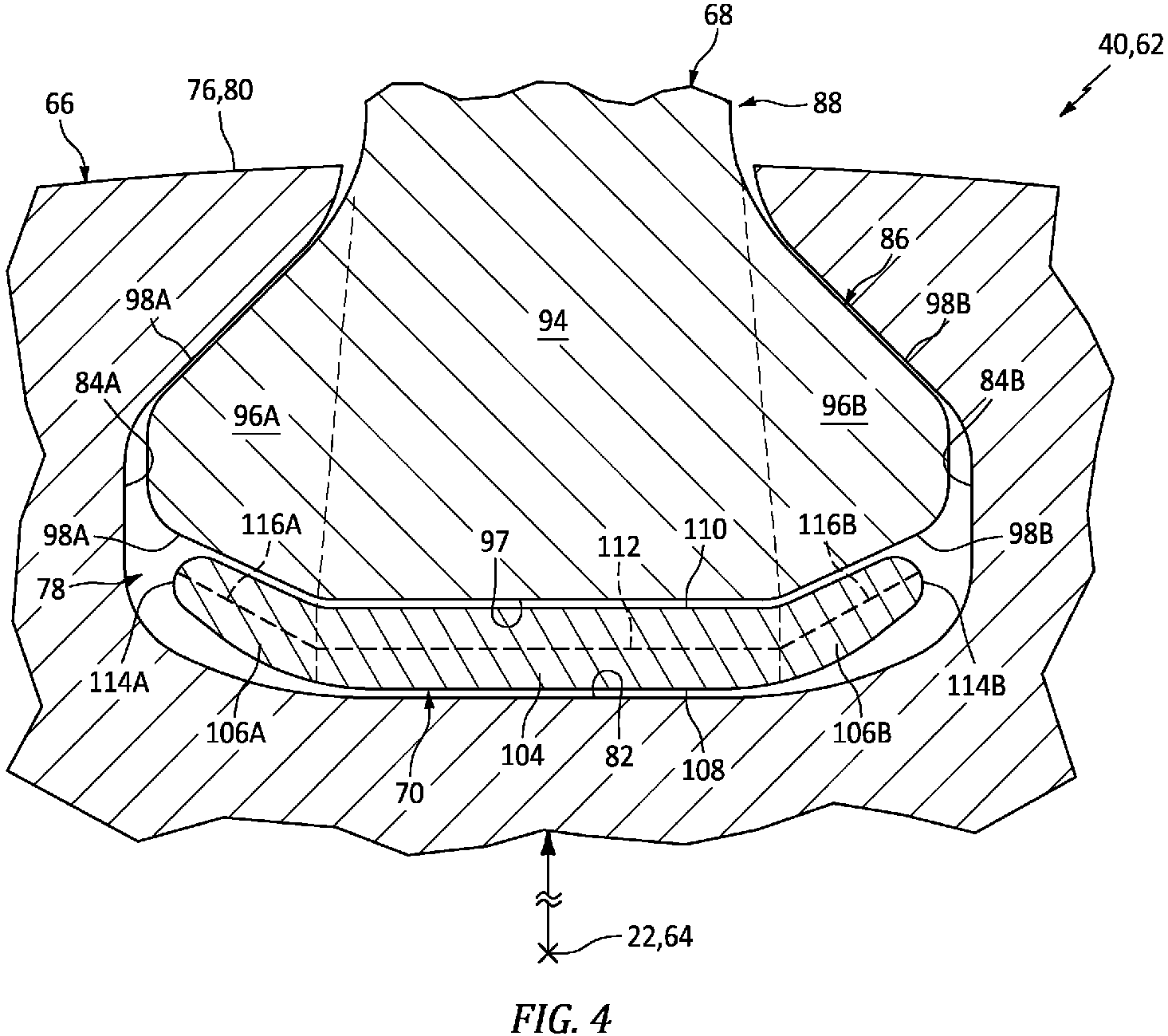
FIG. 4 is a cross-sectional illustration of a portion of the rotor assembly. -
FIG. 5 is a top view illustration of a root spacer. -
FIG. 6 is a sectional illustration of a portion of the root spacer between a rotor disk and a root of a rotor blade. -
FIGS. 7A and7B are illustrations of the root spacer depicting different types of deformation. -
FIGS. 8A and 8B are illustrations of a core element with various different configurations. -
FIGS. 9A-9C are sectional illustrations of a portion of the root spacer with various different core element arrangements. -
FIG. 10 is a sectional illustration of a portion of the root spacer. -
FIG. 11 is a sectional illustration of portions of the same root spacer with different porosities. -
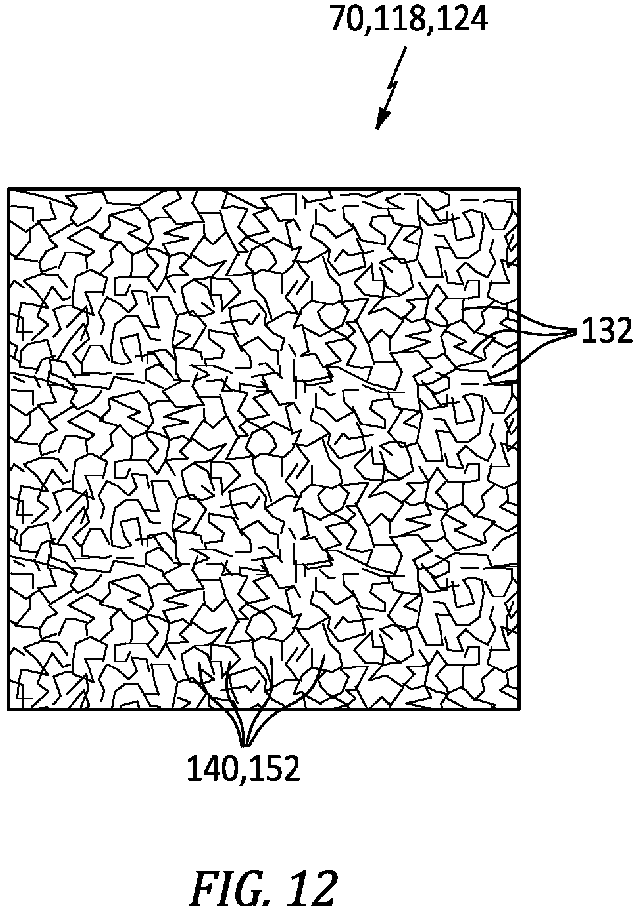
FIG. 12 is a sectional illustration of a portion of the root spacer formed from porous material. -
FIG. 13 is a perspective illustration of a root spacer with a corrugated geometry. -
FIG. 1 is a side cutaway illustration of a gearedgas turbine engine 20. Thisgas turbine engine 20 extends along anaxial centerline 22 between anupstream airflow inlet 24 and adownstream exhaust 26. Thegas turbine engine 20 includes afan section 28, acompressor section 29, acombustor section 30 and aturbine section 31. Thecompressor section 29 includes a low pressure compressor (LPC)section 29A and a high pressure compressor (HPC)section 29B. Theturbine section 31 includes a high pressure turbine (HPT)section 31A and a low pressure turbine (LPT)section 31B. - The engine sections 28-31B are arranged sequentially along the
axial centerline 22 within anengine housing 34. Thisengine housing 34 includes an inner case 36 (e.g., a core case) and an outer case 38 (e.g., a fan case). Theinner case 36 may house one or more of theengine sections 29A-31B; e.g., a core of thegas turbine engine 20. Theouter case 38 may house at least thefan section 28. - Each of the
engine sections - The
fan rotor 40 is connected to ageartrain 46, for example, through afan shaft 48. Thegeartrain 46 and theLPC rotor 41 are connected to and driven by theLPT rotor 44 through alow speed shaft 49. TheHPC rotor 42 is connected to and driven by theHPT rotor 43 through ahigh speed shaft 50. The shafts 48-50 are rotatably supported by a plurality ofbearings 52; e.g., rolling element and/or thrust bearings. Each of thesebearings 52 is connected to theengine housing 34 by at least one stationary structure such as, for example, an annular support strut. - During operation, air enters the
gas turbine engine 20 through theairflow inlet 24. This air is directed through thefan section 28 and into acore flowpath 54 and abypass flowpath 56. Thecore flowpath 54 extends sequentially through theengine sections 29A-31B; e.g., the engine core. The air within thecore flowpath 54 may be referred to as "core air". Thebypass flowpath 56 extends through a bypass duct, which bypass flowpath 56 bypasses (e.g., extends outboard of) the engine core. The air within thebypass flowpath 56 may be referred to as "bypass air". - The core air is compressed by the
LPC rotor 41 and theHPC rotor 42 and directed into a (e.g., annular)combustion chamber 58 of a (e.g., annular)combustor 60 in thecombustor section 30. Fuel is injected into thecombustion chamber 58 through one or more fuel injectors and mixed with the compressed core air to provide a fuel-air mixture. This fuel-air mixture is ignited and combustion products thereof flow through and sequentially cause theHPT rotor 43 and theLPT rotor 44 to rotate. The rotation of theHPT rotor 43 and theLPT rotor 44 respectively drive rotation of theHPC rotor 42 and theLPC rotor 41 and, thus, compression of the air received from an inlet to thecore flowpath 54. The rotation of theLPT rotor 44 also drives rotation of thefan rotor 40, which propels bypass air through and out of thebypass flowpath 56. The propulsion of the bypass air may account for a majority of thrust generated by thegas turbine engine 20, e.g., more than seventy-five percent (75%) of engine thrust. Thegas turbine engine 20 of the present disclosure, however, is not limited to the foregoing exemplary thrust ratio. -
FIG. 2 is a perspective illustration of a partially assembled rotor assembly 62 for one of the above bladed rotors; e.g., thefan rotor 40. This rotor assembly 62 is configured to rotate about a rotational axis 64, which rotational axis 64 may be parallel with (e.g., coaxial with) theaxial centerline 22. The rotor assembly 62 ofFIG. 2 includes arotor disk 66, one or more rotor blades 68 (e.g., fan blades) and one or more root spacers 70 (e.g., fan blade spacers). - The
rotor disk 66 extends axially along the rotational axis 64 between and to a forward,upstream side 72 of therotor disk 66 and an aft,downstream side 74 of therotor disk 66. Therotor disk 66 extends radially out to a distal, outer side 76 of therotor disk 66. Therotor disk 66 extends circumferentially around the rotational axis 64, which provides therotor disk 66 ofFIG. 2 with an annular body. - The
rotor disk 66 includes one or more blade root slots 78 (e.g., dovetail slots) arranged circumferentially about the rotational axis 64 in an array. Referring toFIG. 3 , each of theroot slots 78 each extends longitudinally (e.g., generally axially) into therotor disk 66 from one or both of the disk sides 72 and 74. Eachroot slot 78 ofFIG. 3 , for example, extends longitudinally through therotor disk 66 between and to the diskupstream side 72 and the diskdownstream side 74. Referring toFIG. 4 , each of theroot slots 78 extends radially into therotor disk 66 from an (e.g., segmented) outer surface 80 of therotor disk 66 at the disk outer side 76 to a respectiveslot base surface 82 of therotor disk 66. Each of theroot slots 78 extends laterally (e.g., circumferentially) between a respective set of opposingslot side surfaces rotor disk 66, where the respectiveslot base surface 82 may extend laterally between and to the slot side surfaces 84. - Referring to
FIG. 3 , each of therotor blades 68 includes ablade root 86 and ablade airfoil 88; see alsoFIG. 2 . Theblade root 86 extends longitudinally between a forward,upstream end 90 of theblade root 86 and an aft,downstream end 92 of theblade root 86. Referring toFIG. 4 , theblade root 86 may include aroot base portion 94 and a pair ofroot side portions root base portion 94 extends radially between and to theblade airfoil 88 and aroot base surface 97 of theblade root 86. Theroot side portions root base portion 94 to opposingroot side surfaces blade root 86, where theroot base surface 97 may extend laterally between and to the root side surfaces 98. - Referring to
FIG. 5 , each of theroot spacers 70 extends longitudinally between and to a forwardupstream end 100 of theroot spacer 70 and an aft,downstream end 102 of theroot spacer 70. Theroot spacer 70 ofFIG. 5 includes aspacer base portion 104 and one or morespacer side portions FIG. 4 , each of thespacer portions 104 and 106 extends radially between aninner surface 108 of theroot spacer 70 and anouter surface 110 of theroot spacer 70. Thespacer base portion 104 extends laterally between the spacer side portions 106. Thespacer base portion 104 has a lateralbase portion chord 112. The spacer side portions 106 respectively extend laterally out from thespacer base portion 104 to opposingsides root spacer 70. Each of thespacer side portions side portion chord base portion chord 112 by an obtuse angle; e.g., between one-hundred and thirty-five degrees (135°) and one-hundred and sixty degrees (160°). The present disclosure, however, is not limited to such an exemplary arrangement. - Referring to
FIG. 2 , therotor blades 68 are arranged circumferentially around the rotational axis 64 in an array. Theblade roots 86 and theroot spacers 70 are respectively arranged within theroot slots 78. Referring toFIG. 3 , the spacerupstream end 100 and the rootupstream end 90 may be substantially longitudinally aligned and arranged at (e.g., on, adjacent or proximate) the diskupstream side 72. The spacerdownstream end 102 and the rootdownstream end 92 may be substantially longitudinally aligned and arranged at the diskdownstream side 74. Referring toFIG. 4 , the root side portions 106 extend laterally between theroot base portion 94 and therotor disk 66. Theroot side surfaces slot side surfaces gas turbine engine 20 is operational. Theroot spacer 70 is arranged radially between theblade root 86 and therotor disk 66. The spacerouter surface 110 may engage one or more of the root surfaces 97, 98A and/or 98B; e.g., when thegas turbine engine 20 is operational as well as non-operational. The spacerinner surface 108 may engage theslot base surface 82; e.g., when thegas turbine engine 20 is non-operational. With this arrangement, eachroot spacer 70 may maintain therespective rotor blade 68 in a certain location and/or orientation when thegas turbine engine 20 is non-operational such that, for example, therotor blade 68 does not pitch to its side. - Referring to
FIG. 6 , each of theroot spacers 70 may be configured from or otherwise include a cellular structure 118. The cellular structure 118 ofFIG. 6 includes anouter sidewall 120, aninner sidewall 122 and acellular core 124. - The
outer sidewall 120 may be configured from or otherwise include a solid layer of material; e.g., a non-perforated, non-porous layer of material. Thisouter sidewall 120 at least partially or completely forms the spacerouter surface 110. Theouter sidewall 120 has aradial thickness 126. - The
inner sidewall 122 may be configured from or otherwise include a solid layer of material; e.g., a non-perforated, non-porous layer of material. Thisinner sidewall 122 at least partially or completely forms the spacerinner surface 108. Theinner sidewall 122 has aradial thickness 128 that may be equal to or different (e.g., greater or less) than theouter sidewall thickness 126. - The
cellular core 124 is arranged radially between theouter sidewall 120 and theinner sidewall 122. Thecellular core 124 ofFIG. 6 , for example, extends radially between and to theouter sidewall 120 and theinner sidewall 122. Thecellular core 124 has aradial thickness 130. Thiscellular core thickness 130 may be (e.g., between 2x and 20x) greater than theouter sidewall thickness 126 and/or theinner sidewall thickness 128. Thecellular core thickness 130, for example, may be at least 2x, 4x, 6x, 8x or 10x theouter sidewall thickness 126 and/or theinner sidewall thickness 128. The present disclosure, however, is not limited to such an exemplary arrangement. Furthermore, while thecellular core thickness 130 may be uniform (e.g., constant) laterally and/or longitudinally across theroot spacer 70 and itscellular core 124, thecellular core thickness 130 may alternatively continuously or incrementally change (e.g., increase, decrease and/or undulate) laterally and/or longitudinally across theroot spacer 70 and itscellular core 124. Thecellular core thickness 130, for example, may be locally sized to tailor a root spacer impact response. - The
cellular core 124 is connected to theouter sidewall 120 and theinner sidewall 122. Thecellular core 124, for example, may be formed integral with theouter sidewall 120 and/or theinner sidewall 122 using additive manufacturing, casting, and/or other manufacturing techniques. With such a configuration, thecellular core 124 and, more broadly, theroot spacer 70 may be formed as a single monolithic body. In another example, thecellular core 124 is formed discrete from and then bonded and/or otherwise attached to theouter sidewall 120 and/or theinner sidewall 122. - The cellular structure 118 and its
cellular core 124 and, more generally, theroot spacer 70 are configured to elastically (e.g., temporarily) and/or plastically (e.g., permanently) deform under certain conditions. The cellular structure 118 and itscellular core 124, for example, may be configured to deform when therotor blade 68 exerts more than a threshold load onto theroot spacer 70. This threshold load may be selected to be, for example, slightly (e.g., by a safety factor) less than an impact load that may be exerted when therotor blade 68 comes into contact with a relatively large foreign object; e.g., a relatively large bird. With such an arrangement, theroot spacer 70 may operate as a damper for therotor blade 68 thereby reducing or eliminating impact related damage (e.g., foreign object damage (FOD)) to therotor blade 68. The deformation of the cellular structure 118 and itscellular core 124, for example, may facilitate controlled pitching, pivoting and/or other movement of the impactedrotor blade 68 relative to therotor disk 66. - The
cellular core 124 ofFIG. 6 includes an array ofcore elements 132; e.g., radially members. Referring toFIGS. 7A and7B , one or more or all of thesecore elements 132 is configured to deform such that a value of thecellular core thickness 130 decreases under certain conditions; e.g., during a bird strike. With such deformation, theouter sidewall 120 and theinner sidewall 122 may move radially towards one another; e.g., theouter sidewall 120 may move radially inwards. The cellular structure 118, more particularly, may be compressed locally in one or more discrete regions, or globally such that the entire cellular structure 118 is compressed. Examples of core element deformation include, but are not limited to, bending, buckling and compressing. This deformation may occur elastically and/or plastically. It is also contemplated the deformation may (or may not) result in fracturing, shearing, snapping and/or otherwise breaking members (e.g., 120, 122 and/or 132) of the cellular structure 118. - Each of the
core elements 132 ofFIG. 6 extends radially between and to theouter sidewall 120 and theinner sidewall 122. Each of thecore elements 132 may also be connected to theouter sidewall 120 and/or theinner sidewall 122. Referring toFIG. 8A , each of thesecore elements 132 may be configured as a point protrusion 134 such as, but not limited to, a column or pedestal. Referring toFIG. 8B , one or more or all of thecore elements 132 may also or alternatively be configured as an elongated protrusion 136 such as, but not limited to, a rail or a wall. Referring toFIG. 9A and 9B , at least a portion or an entirety of eachcore element 132 may be laterally and/or longitudinally spaced from (e.g., any) neighboring (e.g., adjacent)core elements 132. Eachcore element 132 ofFIGS. 9A and 9B may thereby be isolated from / disengaged from the other neighboringcore elements 132. Alternatively, referring toFIG. 9C , one or more of thecore elements 132 may be laterally and/or longitudinally engaged. Thecore elements 132 ofFIG. 9C may thereby be interconnected and form a lattice structure. Thecellular core 124 ofFIG. 9C , for example, may be configured as ahoneycomb core 138. - Referring to
FIG. 6 , the spacing between thecore elements 132 provides thecellular core 124 with one or more (e.g., internal)cells 140; e.g., cavities, channels or other apertures. One or more or all of thesecells 140 may be a closed cell where, for example, thecells 140 are fluidly discrete. Some or all of thecells 140 may also or alternatively be an open cell where, for example, thosecells 140 are fluidly coupled (e.g., interconnected) with one another. Eachcell 140 ofFIG. 6 extends (e.g., laterally and/or longitudinally) between neighboringcore elements 132. Eachcell 140 ofFIG. 6 extends radially through thecellular core 124 between and to theouter sidewall 120 and theinner sidewall 122. Theouter sidewall 120 and theinner sidewall 122 may thereby enclose (e.g., cap off) outer and inner ends of eachcell 140. However, in other embodiments, it is contemplated one or more of thecells 140 may alternatively extend radially through the cellular structure 118 to orifices in the spacerouter surface 110 and/or to orifices in the spacerinner surface 108. - Referring to
FIG. 10 , eachcell 140 has alateral width 142. Thislateral width 142 may be sized greater than alateral thickness 144 of an adjacent one of thecore elements 132. Thelateral width 142, however, may be sized smaller than a radial height 146 of thatrespective cell 140. Thelateral width 142 may also or alternatively be sized smaller than aradial thickness 148 of theroot spacer 70 and its cellular structure 118 at (e.g., on, adjacent or proximate) therespective cell 140. Furthermore, while thelateral width 142 may be uniform (e.g., constant) radially, laterally and/or longitudinally across theroot spacer 70 and itscellular core 124, thelateral width 142 may alternatively continuously or incrementally change (e.g., increase, decrease and/or undulate) radially, laterally and/or longitudinally across theroot spacer 70 and itscellular core 124. Thelateral width 142, for example, may be locally sized to tailor a root spacer impact response. The present disclosure, however, is not limited to the foregoing exemplary dimensional relationships. - Referring to
FIG. 6 , the cellular structure 118 and itscellular core 124 may have a uniform (e.g., constant) porosity longitudinally, laterally and/or radially across theroot spacer 70. Here, the term "porosity" may describe a ratio of empty volume (e.g., associated with the cell(s) 140) to filled volume (e.g., associated with the core elements 132). Alternatively, referring toFIG. 11 , the cellular structure 118 and itscellular core 124 may include a plurality ofportions root spacer 70. The different porosity portions 150 may be arranged to tailor root spacer deformation to more effectively damp certain types of impacts against the respective rotor blade 68 (seeFIG. 6 ). - In some embodiments, referring to
FIG. 6 , each core element 132 (e.g., core wall) may have a common (e.g., the same)thickness 151. In other embodiments, thecore element thickness 151 may be different (e.g., larger or smaller) for one or more of thecore element 132 than one or more other of thecore element 132. The core element thicknesses 151, for example, may be locally sized to tailor a root spacer impact response. - In some embodiments, referring to
FIG. 6 , the cellular structure 118 may be or otherwise include an engineered structure such as thecellular core 124 described above. In other embodiments, referring toFIG. 12 , at least a portion or the entire cellular structure 118 (or the cellular core 124) may be formed from material with integral (e.g., internal)cells 140. The cellular structure 118 ofFIG. 12 , for example, is formed from or may otherwise include a foam or other porous material with integral internal pores 152. Each of these pores 152 may form a respective one of thecells 140. The material forming the pores 152 may form thedeformable elements 132. In still other embodiments, referring toFIG. 13 , at least a portion or the entire cellular structure 118 (or the cellular core 124) may be replaced with acorrugated body 154. Thiscorrugated body 154 may provide theroot spacer 70 with a corrugated geometry in a reference plane, for example, perpendicular to the rotational axis 64. Thecorrugated body 154 ofFIG, 13 , for example, includes plurality ofcorrugations 156 arranged laterally between the spacer sides 114. Each of thesecorrugations 156 may extend longitudinally between the spacer ends 100 and 102. - In some embodiments, the
root spacer 70 may be formed from a single material. In other embodiments, theroot spacer 70 may be formed from multiple materials, where the different materials are selectively placed to enhance / tune the deformation. Examples of root spacer materials include, but are not limited to, metal (e.g., aluminum (Al), titanium (Ti) and/or alloys thereof) and composite material (e.g., fiber-reinforced polymer). The present disclosure, however, is not limited to the foregoing exemplary materials. - The rotor assembly 62 and/or its
root spacers 70 may be included in various gas turbine engines other than the one described above. The rotor assembly 62 and/or itsroot spacers 70, for example, may be included in a geared gas turbine engine where a geartrain connects one or more shafts to one or more rotors in a fan section, a compressor section and/or any other engine section. Alternatively, the rotor assembly 62 and/or itsroot spacers 70 may be included in a direct drive gas turbine engine configured without a geartrain. The rotor assembly 62 and/or itsroot spacers 70 may be included in a gas turbine engine configured with a single spool, with two spools (e.g., seeFIG. 1 ), or with more than two spools. The gas turbine engine may be configured as a turbofan engine, a propfan engine, a pusher fan engine or any other type of gas turbine engine. The present disclosure therefore is not limited to any particular types or configurations of gas turbine engines. - While various embodiments of the present disclosure have been described, it will be apparent to those of ordinary skill in the art that many more embodiments and implementations are possible within the scope of the disclosure. For example, the present disclosure as described herein includes several aspects and embodiments that include particular features. Although these features may be described individually, it is within the scope of the present disclosure that some or all of these features may be combined with any one of the aspects and remain within the scope of the disclosure. Accordingly, the present disclosure is not to be restricted except in light of the attached claims and their equivalents.
Claims (15)
- A rotor assembly (62), comprising:a rotor disk (66) including a slot (78);a rotor blade (68) including a blade root (86) arranged within the slot (78); anda root spacer (70) arranged within the slot (78) between the rotor disk (66) and the blade root (86), the root spacer (70) comprising a cellular structure (118) with a plurality of internal cells (140).
- The rotor assembly of claim 1, wherein the plurality of internal cells (140) comprise a plurality of closed cells.
- The rotor assembly of claim 1 or 2, wherein the plurality of internal cells (140) comprise a plurality of open cells.
- The rotor assembly of any preceding claim, whereinthe cellular structure (118) is formed from a porous material; andthe plurality of internal cells (140)comprises a plurality of pores (152) within the porous material.
- The rotor assembly of any preceding claim, wherein the cellular structure (118) includes:a first sidewall (120) engaging the blade root (86);a second sidewall (122) engaging the rotor disk (66); anda cellular core (124), between and connected to the first sidewall (120) and the second sidewall (122), wherein the cellular core (124) optionally comprises a honeycomb core (138).
- The rotor assembly of claim 5, wherein the cellular core (124) includes a plurality of core elements (132) extending between the first sidewall (120) and the second sidewall (122).
- The rotor assembly of claim 6, wherein a first of the plurality of core elements (132) comprises a column (134) and/or a rail (136).
- The rotor assembly of any of claims 5 to 7, wherein at least one ofthe first sidewall (120) is non-perforated; orthe second sidewall (122) is non-perforated.
- The rotor assembly of any preceding claim, whereina first portion (150A) of the cellular structure (118) has a first porosity; anda second portion (150B) of the cellular structure (118) has a second porosity that is different than the first porosity.
- The rotor assembly of any preceding claim, wherein:
the root spacer (70) is radially between the rotor disk (66) and the blade root (86); and either:the root spacer (70) has a radial thickness (148) at a first of the plurality of internal cells (140) and the first of the plurality of internal cells (140) has a lateral width (142) that is less than the radial thickness (148); ora first of the plurality of internal cells (140) has a radial height (146) and a lateral width (142) that is less than the radial height (146). - The rotor assembly of any preceding claim, wherein the rotor blade (68) comprises a gas turbine engine fan blade.
- The rotor assembly of any preceding claim, whereinthe slot (78) is one of a plurality of slots (78) that extend longitudinally into the rotor disk (66);the rotor blade (68) is one of a plurality of rotor blades (68) that are arranged circumferentially around an axis (22, 64), and each of the plurality of rotor blades (68) includes a respective blade root (86) that is arranged within a respective one of the plurality of slots (78); andthe root spacer (70) is one of a plurality of root spacers (70), and each of the plurality of root spacers (70) is arranged within a respective one of the plurality of slots (78) between the rotor disk (66) and a respective one of the plurality of blade roots (86).
- A rotor assembly (62), comprising:a rotor disk (66) including a slot (78);a rotor blade (68) including a blade root (86) arranged within the slot (78); anda root spacer (70) arranged within the slot (78) radially between the rotor disk (66) and the blade root (86), the root spacer (70) configured with a plurality of apertures (140) in the root spacer (70), and a first of the plurality of apertures (140) having a lateral width (142) that is less than a radial thickness (148) of the root spacer (70) at the first of the plurality of apertures (140).
- The rotor assembly of claim 13, wherein the first of the plurality of apertures (140) comprises a cavity embedded within the root spacer (70); and/or wherein the root spacer (70) comprises a cellular core (124) forming the plurality of apertures (140).
- A rotor assembly (62), comprising:a rotor disk (66) including a slot (78), the rotor disk (66) configured to rotate about an axis (22, 64);a rotor blade (68) including a blade root (86) arranged within the slot (78); anda root spacer (70) arranged within the slot (78) between the rotor disk (66) and the blade root (86), the root spacer (70) having a corrugated geometry in a reference plane perpendicular to the axis (22, 64), wherein optionally:the slot (78) extends longitudinally into the rotor disk (66) from an axial side (72; 74) of the rotor disk (66); andthe root spacer (70) comprises a plurality of longitudinally extending corrugations (156).
Applications Claiming Priority (1)
| Application Number | Priority Date | Filing Date | Title |
|---|---|---|---|
| US17/976,345 US12146421B2 (en) | 2022-10-28 | 2022-10-28 | Deformable root spacer for a gas turbine engine rotor blade |
Publications (1)
| Publication Number | Publication Date |
|---|---|
| EP4361402A1 true EP4361402A1 (en) | 2024-05-01 |
Family
ID=88600462
Family Applications (1)
| Application Number | Title | Priority Date | Filing Date |
|---|---|---|---|
| EP23206768.6A Pending EP4361402A1 (en) | 2022-10-28 | 2023-10-30 | Rotor assemblies |
Country Status (2)
| Country | Link |
|---|---|
| US (1) | US12146421B2 (en) |
| EP (1) | EP4361402A1 (en) |
Citations (9)
| Publication number | Priority date | Publication date | Assignee | Title |
|---|---|---|---|---|
| US20050207892A1 (en) * | 2004-02-25 | 2005-09-22 | Mitsubishi Heavy Industries, Ltd. | Rotating blade body and rotary machine using rotating blade body |
| US20130156591A1 (en) * | 2011-12-16 | 2013-06-20 | United Technologies Corporation | Energy absorbent fan blade spacer |
| EP2719865A1 (en) * | 2012-10-12 | 2014-04-16 | MTU Aero Engines GmbH | Insert for disc-blade connections of fluid flow engines |
| US20150252678A1 (en) * | 2014-03-07 | 2015-09-10 | United Technologies Corporation | Fan blade spacer |
| US20160061040A1 (en) * | 2014-08-29 | 2016-03-03 | Rolls-Royce Corporation | Composite fan slider with nano-coating |
| US20160251972A1 (en) * | 2013-10-21 | 2016-09-01 | United Technologies Corporation | Ceramic attachment configuration and method for manufacturing same |
| FR3082555A1 (en) * | 2018-06-18 | 2019-12-20 | Safran Aircraft Engines | RECTIFIER BLADE WHEEL OF AN AIRCRAFT ENGINE, SUCH AS A TURBOJET |
| FR3120389A1 (en) * | 2021-03-04 | 2022-09-09 | Safran Aircraft Engines | Set for a rotor for a turbomachine |
| FR3121171A1 (en) * | 2021-03-25 | 2022-09-30 | Safran Aircraft Engines | Fan rotor for a turbomachine |
Family Cites Families (15)
| Publication number | Priority date | Publication date | Assignee | Title |
|---|---|---|---|---|
| US5259728A (en) * | 1992-05-08 | 1993-11-09 | General Electric Company | Bladed disk assembly |
| US5281096A (en) * | 1992-09-10 | 1994-01-25 | General Electric Company | Fan assembly having lightweight platforms |
| FR2728299B1 (en) * | 1994-12-14 | 1997-01-24 | Snecma | DEVICE FOR AXIAL FIXING OF TURBO-SPINDLE ROTOR BLADES |
| FR2841609B1 (en) | 2002-06-27 | 2004-09-10 | Snecma Moteurs | BLOWER RETAINER LEVEL RETAINER |
| FR2881174B1 (en) | 2005-01-27 | 2010-08-20 | Snecma Moteurs | DEVICE FOR POSITIONING A DASHBOARD AND AUBAGE DISK COMPRISING SUCH A DEVICE |
| FR2918129B1 (en) | 2007-06-26 | 2009-10-30 | Snecma Sa | IMPROVEMENT TO AN INTERCALE BETWEEN A FOOT OF DAWN AND THE BACKGROUND OF THE ALVEOLE OF THE DISK IN WHICH IT IS MOUNTED |
| FR2945074B1 (en) | 2009-04-29 | 2011-06-03 | Snecma | REINFORCED BLOW OF BREATHING BLADE |
| US8616850B2 (en) * | 2010-06-11 | 2013-12-31 | United Technologies Corporation | Gas turbine engine blade mounting arrangement |
| FR2978796B1 (en) | 2011-08-03 | 2013-08-09 | Snecma | TURBOMACHINE AUBES WHEEL |
| US9422819B2 (en) | 2012-12-18 | 2016-08-23 | United Technologies Corporation | Rotor blade root spacer for arranging between a rotor disk and a root of a rotor blade |
| US9359906B2 (en) | 2012-12-18 | 2016-06-07 | United Technologies Corporation | Rotor blade root spacer with a fracture feature |
| US10508556B2 (en) | 2013-01-17 | 2019-12-17 | United Technologies Corporation | Rotor blade root spacer with grip element |
| EP3058179B1 (en) | 2013-10-11 | 2020-01-15 | United Technologies Corporation | Compressible fan blade with root spacer |
| WO2015130377A2 (en) * | 2013-12-12 | 2015-09-03 | United Technologies Corporation | Structural honeycomb panel |
| US10371163B2 (en) * | 2016-02-02 | 2019-08-06 | General Electric Company | Load absorption systems and methods |
-
2022
- 2022-10-28 US US17/976,345 patent/US12146421B2/en active Active
-
2023
- 2023-10-30 EP EP23206768.6A patent/EP4361402A1/en active Pending
Patent Citations (9)
| Publication number | Priority date | Publication date | Assignee | Title |
|---|---|---|---|---|
| US20050207892A1 (en) * | 2004-02-25 | 2005-09-22 | Mitsubishi Heavy Industries, Ltd. | Rotating blade body and rotary machine using rotating blade body |
| US20130156591A1 (en) * | 2011-12-16 | 2013-06-20 | United Technologies Corporation | Energy absorbent fan blade spacer |
| EP2719865A1 (en) * | 2012-10-12 | 2014-04-16 | MTU Aero Engines GmbH | Insert for disc-blade connections of fluid flow engines |
| US20160251972A1 (en) * | 2013-10-21 | 2016-09-01 | United Technologies Corporation | Ceramic attachment configuration and method for manufacturing same |
| US20150252678A1 (en) * | 2014-03-07 | 2015-09-10 | United Technologies Corporation | Fan blade spacer |
| US20160061040A1 (en) * | 2014-08-29 | 2016-03-03 | Rolls-Royce Corporation | Composite fan slider with nano-coating |
| FR3082555A1 (en) * | 2018-06-18 | 2019-12-20 | Safran Aircraft Engines | RECTIFIER BLADE WHEEL OF AN AIRCRAFT ENGINE, SUCH AS A TURBOJET |
| FR3120389A1 (en) * | 2021-03-04 | 2022-09-09 | Safran Aircraft Engines | Set for a rotor for a turbomachine |
| FR3121171A1 (en) * | 2021-03-25 | 2022-09-30 | Safran Aircraft Engines | Fan rotor for a turbomachine |
Also Published As
| Publication number | Publication date |
|---|---|
| US12146421B2 (en) | 2024-11-19 |
| US20240141794A1 (en) | 2024-05-02 |
Similar Documents
| Publication | Publication Date | Title |
|---|---|---|
| EP3896255B1 (en) | Multi-material vane for a gas turbine engine | |
| EP2925970B1 (en) | Trailing edge and tip cooling | |
| EP2333241B1 (en) | Duct with elongated ridge for a gas turbine engine | |
| EP3594452B1 (en) | Seal segment for a gas turbine engine | |
| EP2900929B1 (en) | Fan blade with tall dovetail for individually bladed rotors | |
| US9920634B2 (en) | Method of manufacturing a turbomachine component, an airfoil and a gas turbine engine | |
| EP2984292B1 (en) | Stator vane platform with flanges | |
| WO2015085078A1 (en) | Hollow blade having internal damper | |
| EP2984290B1 (en) | Integrally bladed rotor | |
| EP2971570B1 (en) | Fan blade dovetail and spacer | |
| EP3033493B1 (en) | Coating pocket stress reduction for rotor disk of a gas turbine engine | |
| WO2014052597A1 (en) | Structural guide vane internal topology | |
| EP4361402A1 (en) | Rotor assemblies | |
| EP3896254B1 (en) | Multi-material vane for a gas turbine engine | |
| EP3553283B1 (en) | Gas turbine engine component for acoustic attenuation | |
| EP4365425A1 (en) | Gas turbine engine with third stream | |
| US11859515B2 (en) | Gas turbine engines with improved guide vane configurations | |
| EP3299587B1 (en) | Gas turbine engine airfoil | |
| EP3333365B1 (en) | Stator with support structure feature for tuned airfoil | |
| EP4397847A1 (en) | Engine exhaust center body with acoustic attenuation | |
| US11873730B1 (en) | Gas turbine engine airfoil with extended laminar flow | |
| EP2885503B1 (en) | Integrally bladed rotor | |
| US20240369072A1 (en) | Forward load reduction structures for high pressure compressors | |
| US20220090504A1 (en) | Rotor blade for a gas turbine engine having a metallic structural member and a composite fairing |
Legal Events
| Date | Code | Title | Description |
|---|---|---|---|
| PUAI | Public reference made under article 153(3) epc to a published international application that has entered the european phase |
Free format text: ORIGINAL CODE: 0009012 |
|
| STAA | Information on the status of an ep patent application or granted ep patent |
Free format text: STATUS: THE APPLICATION HAS BEEN PUBLISHED |
|
| AK | Designated contracting states |
Kind code of ref document: A1 Designated state(s): AL AT BE BG CH CY CZ DE DK EE ES FI FR GB GR HR HU IE IS IT LI LT LU LV MC ME MK MT NL NO PL PT RO RS SE SI SK SM TR |
|
| STAA | Information on the status of an ep patent application or granted ep patent |
Free format text: STATUS: REQUEST FOR EXAMINATION WAS MADE |
|
| 17P | Request for examination filed |
Effective date: 20241031 |
|
| RBV | Designated contracting states (corrected) |
Designated state(s): AL AT BE BG CH CY CZ DE DK EE ES FI FR GB GR HR HU IE IS IT LI LT LU LV MC ME MK MT NL NO PL PT RO RS SE SI SK SM TR |