EP4361247A1 - Cell thawing machine and method for operating same - Google Patents
Cell thawing machine and method for operating same Download PDFInfo
- Publication number
- EP4361247A1 EP4361247A1 EP22828696.9A EP22828696A EP4361247A1 EP 4361247 A1 EP4361247 A1 EP 4361247A1 EP 22828696 A EP22828696 A EP 22828696A EP 4361247 A1 EP4361247 A1 EP 4361247A1
- Authority
- EP
- European Patent Office
- Prior art keywords
- heating
- heating block
- block
- container
- cell thawing
- Prior art date
- Legal status (The legal status is an assumption and is not a legal conclusion. Google has not performed a legal analysis and makes no representation as to the accuracy of the status listed.)
- Pending
Links
Images












Classifications
-
- B—PERFORMING OPERATIONS; TRANSPORTING
- B01—PHYSICAL OR CHEMICAL PROCESSES OR APPARATUS IN GENERAL
- B01L—CHEMICAL OR PHYSICAL LABORATORY APPARATUS FOR GENERAL USE
- B01L7/00—Heating or cooling apparatus; Heat insulating devices
- B01L7/52—Heating or cooling apparatus; Heat insulating devices with provision for submitting samples to a predetermined sequence of different temperatures, e.g. for treating nucleic acid samples
-
- B—PERFORMING OPERATIONS; TRANSPORTING
- B01—PHYSICAL OR CHEMICAL PROCESSES OR APPARATUS IN GENERAL
- B01L—CHEMICAL OR PHYSICAL LABORATORY APPARATUS FOR GENERAL USE
- B01L7/00—Heating or cooling apparatus; Heat insulating devices
-
- B—PERFORMING OPERATIONS; TRANSPORTING
- B01—PHYSICAL OR CHEMICAL PROCESSES OR APPARATUS IN GENERAL
- B01L—CHEMICAL OR PHYSICAL LABORATORY APPARATUS FOR GENERAL USE
- B01L7/00—Heating or cooling apparatus; Heat insulating devices
- B01L7/54—Heating or cooling apparatus; Heat insulating devices using spatial temperature gradients
-
- C—CHEMISTRY; METALLURGY
- C12—BIOCHEMISTRY; BEER; SPIRITS; WINE; VINEGAR; MICROBIOLOGY; ENZYMOLOGY; MUTATION OR GENETIC ENGINEERING
- C12M—APPARATUS FOR ENZYMOLOGY OR MICROBIOLOGY; APPARATUS FOR CULTURING MICROORGANISMS FOR PRODUCING BIOMASS, FOR GROWING CELLS OR FOR OBTAINING FERMENTATION OR METABOLIC PRODUCTS, i.e. BIOREACTORS OR FERMENTERS
- C12M45/00—Means for pre-treatment of biological substances
- C12M45/22—Means for packing or storing viable microorganisms
-
- C—CHEMISTRY; METALLURGY
- C12—BIOCHEMISTRY; BEER; SPIRITS; WINE; VINEGAR; MICROBIOLOGY; ENZYMOLOGY; MUTATION OR GENETIC ENGINEERING
- C12N—MICROORGANISMS OR ENZYMES; COMPOSITIONS THEREOF; PROPAGATING, PRESERVING, OR MAINTAINING MICROORGANISMS; MUTATION OR GENETIC ENGINEERING; CULTURE MEDIA
- C12N5/00—Undifferentiated human, animal or plant cells, e.g. cell lines; Tissues; Cultivation or maintenance thereof; Culture media therefor
- C12N5/54—Mechanical aspects of preservation of animal cells or human cells; Apparatus or containers therefor
- C12N5/542—Apparatus
-
- B—PERFORMING OPERATIONS; TRANSPORTING
- B01—PHYSICAL OR CHEMICAL PROCESSES OR APPARATUS IN GENERAL
- B01L—CHEMICAL OR PHYSICAL LABORATORY APPARATUS FOR GENERAL USE
- B01L2200/00—Solutions for specific problems relating to chemical or physical laboratory apparatus
- B01L2200/02—Adapting objects or devices to another
- B01L2200/025—Align devices or objects to ensure defined positions relative to each other
-
- B—PERFORMING OPERATIONS; TRANSPORTING
- B01—PHYSICAL OR CHEMICAL PROCESSES OR APPARATUS IN GENERAL
- B01L—CHEMICAL OR PHYSICAL LABORATORY APPARATUS FOR GENERAL USE
- B01L2200/00—Solutions for specific problems relating to chemical or physical laboratory apparatus
- B01L2200/14—Process control and prevention of errors
- B01L2200/143—Quality control, feedback systems
- B01L2200/147—Employing temperature sensors
-
- B—PERFORMING OPERATIONS; TRANSPORTING
- B01—PHYSICAL OR CHEMICAL PROCESSES OR APPARATUS IN GENERAL
- B01L—CHEMICAL OR PHYSICAL LABORATORY APPARATUS FOR GENERAL USE
- B01L2300/00—Additional constructional details
- B01L2300/02—Identification, exchange or storage of information
- B01L2300/025—Displaying results or values with integrated means
-
- B—PERFORMING OPERATIONS; TRANSPORTING
- B01—PHYSICAL OR CHEMICAL PROCESSES OR APPARATUS IN GENERAL
- B01L—CHEMICAL OR PHYSICAL LABORATORY APPARATUS FOR GENERAL USE
- B01L2300/00—Additional constructional details
- B01L2300/06—Auxiliary integrated devices, integrated components
- B01L2300/0609—Holders integrated in container to position an object
-
- B—PERFORMING OPERATIONS; TRANSPORTING
- B01—PHYSICAL OR CHEMICAL PROCESSES OR APPARATUS IN GENERAL
- B01L—CHEMICAL OR PHYSICAL LABORATORY APPARATUS FOR GENERAL USE
- B01L2300/00—Additional constructional details
- B01L2300/06—Auxiliary integrated devices, integrated components
- B01L2300/0627—Sensor or part of a sensor is integrated
- B01L2300/0663—Whole sensors
-
- B—PERFORMING OPERATIONS; TRANSPORTING
- B01—PHYSICAL OR CHEMICAL PROCESSES OR APPARATUS IN GENERAL
- B01L—CHEMICAL OR PHYSICAL LABORATORY APPARATUS FOR GENERAL USE
- B01L2300/00—Additional constructional details
- B01L2300/08—Geometry, shape and general structure
- B01L2300/0809—Geometry, shape and general structure rectangular shaped
-
- B—PERFORMING OPERATIONS; TRANSPORTING
- B01—PHYSICAL OR CHEMICAL PROCESSES OR APPARATUS IN GENERAL
- B01L—CHEMICAL OR PHYSICAL LABORATORY APPARATUS FOR GENERAL USE
- B01L2300/00—Additional constructional details
- B01L2300/12—Specific details about materials
- B01L2300/123—Flexible; Elastomeric
-
- B—PERFORMING OPERATIONS; TRANSPORTING
- B01—PHYSICAL OR CHEMICAL PROCESSES OR APPARATUS IN GENERAL
- B01L—CHEMICAL OR PHYSICAL LABORATORY APPARATUS FOR GENERAL USE
- B01L2300/00—Additional constructional details
- B01L2300/18—Means for temperature control
- B01L2300/1805—Conductive heating, heat from thermostatted solids is conducted to receptacles, e.g. heating plates, blocks
-
- B—PERFORMING OPERATIONS; TRANSPORTING
- B01—PHYSICAL OR CHEMICAL PROCESSES OR APPARATUS IN GENERAL
- B01L—CHEMICAL OR PHYSICAL LABORATORY APPARATUS FOR GENERAL USE
- B01L2300/00—Additional constructional details
- B01L2300/18—Means for temperature control
- B01L2300/1883—Means for temperature control using thermal insulation
-
- B—PERFORMING OPERATIONS; TRANSPORTING
- B01—PHYSICAL OR CHEMICAL PROCESSES OR APPARATUS IN GENERAL
- B01L—CHEMICAL OR PHYSICAL LABORATORY APPARATUS FOR GENERAL USE
- B01L9/00—Supporting devices; Holding devices
- B01L9/06—Test-tube stands; Test-tube holders
-
- C—CHEMISTRY; METALLURGY
- C12—BIOCHEMISTRY; BEER; SPIRITS; WINE; VINEGAR; MICROBIOLOGY; ENZYMOLOGY; MUTATION OR GENETIC ENGINEERING
- C12M—APPARATUS FOR ENZYMOLOGY OR MICROBIOLOGY; APPARATUS FOR CULTURING MICROORGANISMS FOR PRODUCING BIOMASS, FOR GROWING CELLS OR FOR OBTAINING FERMENTATION OR METABOLIC PRODUCTS, i.e. BIOREACTORS OR FERMENTERS
- C12M45/00—Means for pre-treatment of biological substances
- C12M45/20—Heating; Cooling
Definitions
- the present invention relates to a cell thawing machine and an operating method thereof.
- various biological materials are stored at low temperature after being stored in containers such as vials.
- plasma and tissue cells are stored at a maximum of -100 degrees Celsius
- stem cells are stored at cryogenic temperatures of up to -165 degrees Celsius by using gaseous liquid nitrogen.
- a cell thawing machine has been proposed for thawing a biological material in a low-temperature state by heating a container such as a vial in which the biological material is stored.
- conventional cell thawing machines adopt a method of transferring heat while a heating block and a container are in contact with each other. Accordingly, the conventional cell thawing machines have a problem in that it is difficult to uniformly heat the container as a whole, and since the high-temperature heating block directly contacts the container, there is a problem in that the container is cracked or deformed by the high temperature.
- the conventional cell thawing machine was a method of simply displaying whether the heating block was operating normally through an indicator such as an LED.
- the conventional cell thawing machines have a problem in that the operating temperature of the heating block cannot be easily measured during qualification evaluation to determine whether the heating block operates correctly.
- the present invention has been devised in view of the above points, and an object of the present invention is to provide a cell thawing machine which is capable of uniformly heating the container as a whole while securing the heat stability of the container including the biological material during the heating process, and an operation method thereof.
- Another object of the present invention is to provide a cell thawing machine which is capable of increasing energy use efficiency and an operating method thereof.
- Still another object of the present invention is to provide a cell thawing machine which is capable of conveniently measuring the operating temperature of a heating block during qualification evaluation.
- the present invention provides a cell thawing machine, including a thawing part including a heating block which includes a first heating block and a second heating block that form a heating space for heating a container in which a predetermined amount of biological material including cells is stored, a heater which is installed in the heating block to provide heat to the heating block, a heat insulating block which is coupled to the heating block to surround the heater, and a pedestal which is configured to support a lower portion of the container in the heating space; a driving part for providing a driving force that linearly moves each of the first heating block and the second heating block in left and right directions; a sensing part including a sensor for detecting the state of the container disposed in the heating space, and a mounting member on which the sensor is mounted and which moves in forward and backward directions in connection with the operation of the driving part; and a control part for controlling the operations of the thawing part, the driving part and the sensing part.
- a heating block which includes a first heating block and a second heating block that
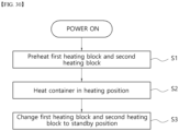
- the present invention provides a method for operating a cell thawing machine including a heating block including a first heating block and a second heating block which form a heating space for heating a container in which a predetermined amount of biological material including cells is stored through linear movement by a driving force of a motor, and heat the container accommodated in the heating space through heat provided from a heater; and a sensor for changing a position in connection with the linear movement of the heating block and detecting the state of the container disposed in the heating space, the method including a first step of preheating the first heating block and the second heating block to a predetermined temperature by driving the heater while one surface of the first heating block and one surface of the second heating block facing each other are in contact with each other; a second step of heating the container disposed in the heating space to thaw the biological material while the first heating block and the second heating block are changed to a heating position forming the heating space; and a third step of changing the first and second heating blocks to a standby position by moving the same in a direction of
- the container can be uniformly heated by heating the container in a non-contact heating manner by using radiant heat, and it is possible to prevent cracks or thermal deformation of the container that may occur during heating by conductive heat in advance.
- the present invention since the temperature of the heating block can be maintained to be constant, a plurality of containers can be sequentially thawed. Through this, the present invention can improve energy consumption efficiency, because it is possible to thaw a plurality of containers while reducing the reuse waiting time for thawing containers.
- the sensor insertion hole for qualification evaluation is exposed to the outside such that it is possible to easily perform qualification evaluation.
- the cell thawing machines 100, 200 may heat and thaw biological materials in a low-temperature state (e.g., frozen state) contained in a container 10.
- a low-temperature state e.g., frozen state
- the biological material may include cells, which are the structural basic unit of an organism, and the container 10 may be a known laboratory container or a container for medical use, such as a vial, a beaker or a test tube.
- the container 10 may include a container main body 12 in which the biological material is accommodated, a cap part 14 for covering an open upper portion of the container main body 12, and a flange part 16 which is formed to protrude from a lower portion of the container main body 12, and a biological material of about 2 mL capacity may be contained in the container main body 12.
- a biological material of about 2 mL capacity may be contained in the container main body 12.
- the shape of the container 10 and the capacity of the biological material contained in the container main body 12 are not limited thereto and may be changed into various shapes depending on design conditions.
- the cell thawing machines 100, 200 may heat the container 10 uniformly as a whole by heating the container 10 in a non-contact heating manner through radiant heat and/or convection heat, and it is possible to prevent cracks or thermal deformation of the container 10 that may occur during contact heating by conductive heat in advance.
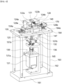
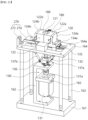
- the cell thawing machines 100, 200 include a housing 110, a thawing part 120, a driving part 130, a sensing part 140 and a control part 150.
- the housing 110 may form an outer surface of the cell thawing machine 100, 200, and it may be formed in a box shape such that the thawing part 120, the driving part 130, the sensing part 140 and the control part 150 can be disposed therein.
- the housing 110 may be composed of one member or may be composed of a plurality of members, and the plurality of members may be detachably coupled.
- the housing 110 may include a box-shaped main body 111, a lower cover 112 for covering an open lower portion of the main body 111, a rear cover 113 for covering an open rear surface of the main body 111, and an upper cover 114 for covering an upper portion of the main body 111.
- the thawing part 120, the driving part 130, the sensing part 140 and the control part 150 may be disposed inside the main body 111.
- the housing 110 may include an inlet 115 which is formed to penetrate a predetermined area such that the container 10 can be inserted into the main body 111, and the inlet 115 may be covered through a cover 116.
- the inlet 115 may be formed to penetrate the housing 110 so as to be located at a position corresponding to a heating space 121 to be described below.
- the inlet 115 may be formed to penetrate the upper cover 114 to communicate with a heating space 121 formed in the thawing part 120 at a heating position to be described below.
- the cap part 14 of the container 10 may be exposed to the outside through the inlet 115, and the remaining portion except for the cap part 14 may be inserted into the heating space 121.
- a manipulation part 117 for manipulating the operation of the cell thawing machines 100, 200 according to one embodiment of the present invention, and a display 118 for displaying the operating state of the cell thawing machines 100, 200 may be provided on one side of the housing 110.
- Such a manipulation part 117 may be an interface for transmitting an input signal to the control part 150 through user manipulation.
- the manipulation part 117 may be configured with a known press-type physical button or capacitive touch button.
- the display 118 may be provided separately from the display 118, it may be provided in an integrated form with the display 118.
- the display 118 may output information on the overall operating state of the cell thawing machines 100, 200 operated through the control part 150 (e.g., the operating status such as the temperature of the heating blocks 122a, 122b, the surface temperature of the container 10, thawing or completion of thawing, or thawing progress time), date and time at the time of thawing, an error message such as sensor or heater failure, which will be described below, and the like.
- the operating status such as the temperature of the heating blocks 122a, 122b, the surface temperature of the container 10, thawing or completion of thawing, or thawing progress time
- date and time at the time of thawing e.g., the time at the time of thawing, an error message such as sensor or heater failure, which will be described below, and the like.
- the user may transmit input signals, such as operation and stop of the cell thawing machines 100, 200, thawing temperature adjustment and thawing time adjustment, to the control part 150 through manipulation of the manipulation part 117, and the display 118 may output information on the overall state of the cell thawing machines 100, 200 through the control part 150.
- input signals such as operation and stop of the cell thawing machines 100, 200, thawing temperature adjustment and thawing time adjustment
- the cell thawing machines 100, 200 may include at least one communication port 119 that is provided to be exposed to the outside from one side of the housing 110, and the communication port 119 may be electrically connected to the control part 150.
- the communication port 119 may include a LAN port 119a for communication with communication equipment such as an external network device or a PC, and a USB port 119b for inputting or outputting data, and the communication port 119 may be mounted on the rear cover 113 so as to be electrically connected to the control part 150.
- the control part 150 may be time-synchronized with communication equipment such as the external network device or PC.
- the cell thawing machines 100, 200 when the cell thawing machines 100, 200 are connected to a PC such as a laptop computer, the cell thawing machines 100, 200 may be synchronized with the date and time of the PC by using a synchronization program installed in the PC.
- the cell thawing machines 100, 200 may be synchronized with the local time of the region where thawing is performed when in use, and the local time of the region may be output through the display 118.
- the cell thawing machines 100, 200 may store history information about the exact time of thawing of the biological material contained in the container 10, and the user may confirm the exact thawing time of the biological material contained in the container 10 through the history information.
- information related to thawing may be stored in the cell thawing machines 100, 200 themselves or may be stored in a synchronization program of a communication device that is connected through the communication port 119.
- the information related to thawing stored in the cell thawing machines 100, 200 or the synchronization program may be stored by date
- a thawing history may be stored for each thawing case, and the thawing history may include the local time of the region where the thawing is performed.
- the thawing part 120 may heat the container 10 while the container 10 introduced into the housing 110 through the inlet 115 is accommodated in a heating space 121.
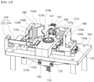
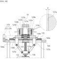
- the thawing part 120 may include heating blocks 122a, 122b for forming a heating space 121 for accommodating the container 10, heaters 123a, 123b which are installed on the heating blocks 122a, 122b to provide heat to the heating blocks 122a, 122b, and heat insulating blocks 124a, 124b which are coupled to the heating blocks 122a, 122b so as to surround the heaters 123a, 123b, and a pedestal 125 for supporting a lower portion of the container 10 in the heating space 121.
- the lower portion of the container 10 may be supported through a pedestal 125, and the container 10 may be surrounded through the heating blocks 122a, 122b while being accommodated in the heating space 121 (refer to FIGS. 16 , 19 and 28 ).
- the heating blocks 122a, 122b may include arrangement grooves 126a, 126b which are formed to be drawn inward on one surface, and the heaters 123a, 123b may be inserted into the arrangement grooves 126a, 126b, and the heat insulating blocks 124a, 124b may be coupled to the heating blocks 122a, 122b so as to completely cover the arrangement grooves 126a, 126b while the heaters 123a, 123b are inserted into the arrangement grooves 126a, 126b.
- the heating blocks 122a, 122b may be made of a material having thermal conductivity such as metal, and the heat insulating blocks 124a, 124b may be made of a material having heat insulation property.
- the heating blocks 122a, 122b may be heated by the heat generated from the heaters 123a, 123b, and the heat generated from the heaters 123a, 123b may be concentrated toward the heating blocks 122a, 122b by limiting the direction of heat movement through the heat insulating blocks 124a, 124b, and the heat transferred from the heaters 123a, 123b to the heating blocks 122a, 122b may be transferred toward the heating space 121.
- the container 10 may be heated by the heat provided from the heating blocks 122a, 122b, and the biological material stored in the container 10 may be thawed by the heat.
- the cell thawing machines 100, 200 may improve energy consumption efficiency.
- the container 10 accommodated in the heating space 121 may be heated by using the heat of the heating blocks 122a, 122b that are heated to a constant temperature by the heat transferred from the heaters 123a, 123b, the circumferential surface of the container 10 may be heated to a uniform temperature.
- the circumferential surface of the container 10 may be the circumferential surface of the container main body 12 excluding the cap part 14 and the flange part 16.
- the thawing part 120 may include temperature sensors 128a, 128b which are installed on the heating blocks 122a, 122b so as to measure the temperature of the heating blocks 122a, 122b.
- the temperature sensors 128a, 128b may be known contact-type temperature sensors such as thermocouples, resistance thermometers (RTDs) and thermistors, and the temperatures of the heating blocks 122a, 122b measured through the temperature sensors 128a, 128b may be transmitted to the control part 150.
- control part 150 may control the driving of the heaters 123a, 123b based on the temperature information measured by the temperature sensors 128a, 128b to maintain the temperatures of the heating blocks 122a, 122b to constant temperatures.
- control part 150 may maintain the temperatures of the heating blocks 122a, 122b to be constant by controlling the driving of the heaters 123a, 123b through PID control.
- control part 150 may prevent overheating of the heating blocks 122a, 122b by controlling driving of the heaters 123a, 123b based on the temperature information measured by the temperature sensors 128a, 128b.
- the heaters 123a, 123b may be ceramic heaters to secure reliability and improve the lifespan cycle of products even under operating conditions in which heating and cooling are repeatedly performed, but the present invention not limited thereto, and various known heaters may be applied.
- the heating space 121 may be provided in a shape corresponding to the shape of the container 10, and the heating space 121 may be formed through at least two heating blocks 122a, 122b.
- the heating blocks 122a, 122b may include a first heating block 122a and a second heating block 122b that are disposed such that surfaces thereof face each other, and the heating space 121 may be formed through a pair of opposing surfaces 127a, 127b that are formed to be drawn on surfaces facing each other on the first heating block 122a and the second heating block 122b, respectively.
- the pair of opposing surfaces 127a, 127b may be drawn inward to have a shape corresponding to the circumferential surface of the container 10.
- the pair of opposing surfaces 127a, 127b may be arc-shaped curved surfaces, and when the container 10 is formed in the shape of a square column, the pair of opposing surfaces 127a, 127b may be formed as bent surfaces having a substantially 'c' cross-sectional shape.
- the container 10 when the container 10 is introduced into the heating space 121 through the inlet 115, the container 10 may be completely surrounded by a pair of opposing surfaces 127a, 127b on which the circumferential surface thereof defines the heating space 121.
- the circumferential surface of the container 10 accommodated in the heating space 121 may be uniformly heated by the heat provided from the first heating block 122a and the second heating block 122b.
- each of the first heating block 122a and the second heating block 122b may include arrangement grooves 126a, 126b that are formed to be drawn inward on one surface thereof, respectively, and the heaters 123a, 123b may include a first heater 123a and a second heater 123b that are disposed to be inserted into the arrangement groove 126a formed in the first heating block 122a and the arrangement groove 126b formed in the second heating block 122b, respectively.
- the heat insulating blocks 124a, 124b may include a first heat insulating block 124a and a second heat insulating block 124b, and the first heat insulating block 124a may be coupled to the first heating block 122a so as to completely cover the arrangement groove 126a while the first heater 123a is inserted into the arrangement groove 126a of the first heating block 122a, and the second heat insulating block 124b may be coupled to the second heating block 122b so as to completely cover the arrangement groove 126b while the second heater 123b is inserted into the arrangement groove 126b of the second heating block 122b.
- the temperature sensors 128a, 128b may include a first temperature sensor 128a which is installed in the first heating block 122a to measure the temperature of the first heating block 122a, and a second temperature sensor 128b which is installed in the second heating block 122b to measure the temperature of the second heating block 122b.
- the heat generated from the first heater 123a may heat the first heating block 122a
- the heat generated from the second heater 123b may heat the second heating block 122b
- the control part 150 may control the driving of the first heater 123a and the second heater 123b based on the temperature information measured by the first temperature sensor 128a and the second temperature sensor 128b such that it is possible to maintain the temperatures of the first heating block 122a and the second heating block 122b to be constant.
- control part 150 may control the operations of the first heater 123a and the second heater 123b together based on the temperature information measured through the first temperature sensor 128a and the second temperature sensor 128b, or the control part 150 may individually control the operations of the first heater 123a and the second heater 123b based on the temperature information measured through the first temperature sensor 128a and the second temperature sensor 128b.
- the temperatures of the first heating block 122a and the second heating block 122b may be precisely controlled through the control of the control part 150.
- the circumferential surface of the container 10 may be uniformly heated.
- control part 150 individually controls the driving of the first heater 123a and the second heater 123b
- the user may immediately check an anomaly of the corresponding part based on the information output through the display 118, and take appropriate action on the corresponding part in which the abnormality occurred.
- the user may immediately check an abnormality of the corresponding part based on the information output through the display 118, and take appropriate action on the corresponding part in which the abnormality has occurred.
- the container 10 accommodated in the heating space 121 does not contact the heating block 122a, 122b
- the container 10 may be heated by the heat transferred from the heating block 122a., 122b in a non-contact manner.
- the circumferential surface of the container 10 may be spaced apart by a certain interval from the opposing surface 127a of the first heating block 122a and the opposing surface 127b of the second heating block 122b forming the heating space 121.
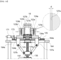
- a gap (d) may be formed between the pair of opposing surfaces 127a, 127b and the outer surface of the container 10.
- the heat stored in the first heating block 122a and the second heating block 122b may be transferred to the relatively low-temperature container 10 through convection and/or radiation instead of conduction.
- the cell thawing machines 100, 200 may heat the circumferential surface of the container 10 through heat transfer using convection and/or radiation, the circumferential surface of the container 10 may be uniformly heated through convective heat and/or radiant heat transmitted from the heating blocks 122a, 122b.
- the cell thawing machines 100, 200 may uniformly heat the circumferential surface of the container through convective heat and/or radiant heat, and thus, it is possible to prevent the concentration of heat in a local location of the container 10.
- the first heating block 122a and the second heating block 122b do not come into direct contact with the container 10, and thus, it is possible to prevent cracks or thermal deformation of the container that may occur due to heat when in direct contact with a high-temperature obj ect.
- the gap (d) between the pair of opposing surfaces 127a, 127b forming the heating space 121 and the outer surface of the container 10 may be 0.2 mm to 0.3 mm, but the present invention is limited thereto, and the size of the gap (d) may be appropriately changed depending on the overall size of the container 10.
- At least any one of the first heating block 122a and the second heating block 122b may be linearly moved reciprocally in a straight line, and the heating space 121 may be formed when the first heating block 122a and the second heating block 122b are disposed to be located in nearby positions through the linear movement of at least any one of the first heating block 122a and the second heating block 122b.
- the detailed description thereof will be described below.
- the pedestal 125 for supporting a lower portion of the container 10 may include a seating groove 125a which is formed on one surface supporting a lower portion of the container 10 in order to allow a lower edge of the container 10 to be inserted, and a protruding member 125d which is formed to protrude at a certain height such that the lower surface of the container 10 can be spaced apart at a certain height from one surface of the pedestal 125.
- the seating groove 125a may stably support the container 10 by fixing the lower edge of the container 10.
- the protruding member 125d may support the lower surface of the container 10 such that the lower surface of the container 10 is spaced apart at a certain height from one surface of the pedestal 125.
- the seating groove 125a may be formed in a shape corresponding to a flange part 16 such that the flange part 16 formed along the lower edge of the container 10 can be inserted therein, and as illustrated in FIGS. 9 and 10 , the seating groove 125a may be formed to be located outside the protruding member 125d along the circumferential direction of the protruding member 125d.
- the lower surface of the container 10 may be supported by one surface of the protruding member 125d, and the flange part 16 may be inserted into the seating groove 125a, and the container 10 in which the flange part 16 is inserted into the seating groove 125a may maintain an upright state without tilting in any direction.
- the container 10 disposed in the heating space 121 is correctly positioned such that the circumferential surface thereof faces a pair of opposing surfaces 127a and 127b forming the heating space 121 in the heating space 121, it may maintain a uniform gap with the pair of opposing surfaces 127a, 127b.
- the driving part 130 may linearly move the heating blocks 122a, 122b in left and right directions.
- the heating blocks 122a, 122b include a first heating block 122a and a second heating block 122b
- the driving part 130 may linearly move at least any one of the first heating block 122a and the second heating block 122b reciprocally in the left and right directions.
- the driving part 130 may linearly move the first heating block 122a and the second heating block 122b reciprocally in the left and right directions, respectively.
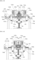
- the cell thawing machines 100, 200 may be changed to a heating position in which the first heating block 122a and the first heating block 122a are disposed to be close to each other through the driving of the driving part 130, and a standby position in which the first heating block 122a and the second heating block 122b are disposed to be spaced apart from each other at a gap through the driving of the driving part 130 as illustrated in FIGS. 13 , 15 , 17 , 25 , 27 and 29 .
- a heating space 121 for accommodating the container 10 to heat the container 10 may be formed between the opposing surface 127a of the first heating block 122a and the opposing surface 127b of the second heating block 122b.
- a gap between the opposing surface 127a of the first heating block 122a and the opposing surface 127b of the second heating block 122b may be widened.
- the user may easily introduce the container 10 to be disposed between the first heating block 122a and the second heating block 122b or may easily remove the container 10 which is disposed between the first heating block 122a and the second heating block 122b.
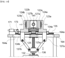
- the driving part 130 may include a motor 131 for providing a driving force, a rotating member 132 which is axially coupled to a rotating shaft 131a of the motor 131, and a power transmission member for interconnecting the rotating member 132 and the thawing part 120 so as to linearly move the first heating block 122a and the second heating block 122b, respectively, when the motor 131 is driven.
- the power transmission member may include guide blocks 134a, 134b which are fixedly coupled to the heat insulating blocks 124a, 124b, guide rails 135 for guiding linear movement of the guide blocks 134a, 134b, a moving member 136 which moves up and down in the top and down directions along the rotating member 132 when the motor 131 is driven, and link members 137a, 137b for linking the guide blocks 134a, 134b and the moving member 136 to each other.
- the guide blocks 134a, 134b may include a first guide block 134a which is fixedly coupled to the first heat insulating block 124a and a second guide block 134b which is fixedly coupled to the second heat insulating block 124b, the first guide block 134a and the second guide block 134b may be coupled to the guide rail 135 so as to be slidably movable.
- link members 137a, 137b may include a first link member 137a for linking the moving member 136 and the first guide block 134a to each other, and a second link member 137b for linking the moving member 136 and the second link member 137b to each other.
- the cell thawing machines 100, 200 may further include a base 161, a mounting table 162, a support bar 163 and a support 164 that are disposed inside the housing 110.
- a mounting table 162 may be fixedly coupled to an upper surface of the base 161, and the motor 131 may be fixedly coupled to one side of the mounting table 162 via a coupling base 165, and the rotating member 132 which is axially coupled to a rotating shaft 131a of the motor 131 may be rotatably coupled to the mounting table 162.
- the plate-shaped support 164 having a predetermined area may be disposed at a certain interval from an upper portion from the base 161 through at least one support bar 163 having a predetermined length and one end of which is fixedly coupled to the base 161, and the guide rail 135 and the pedestal 125 may be fixedly coupled to one surface of a support 164.
- first guide block 134a and the second guide block 134b may be slidably coupled to the guide rail 135, and the first heat insulating block 124a may be fixedly coupled to the first guide block 134a, and the second heat insulating block 124b may be fixedly coupled to the second guide block 134b.
- the rotating member 132 may be a screw bar having a predetermined length and having one end axially coupled to a rotating shaft 131a of the motor 131, and the moving member 136 may be screw-coupled to the rotating member 132 to be movable.
- the support 164 may include a through-hole 164a having a long hole through which the first link member 137a and the second link member 137b may respectively pass.
- both ends of the first link member 137a may be linked to the rotating member 132 and the first guide block 134a, respectively, and both ends of the second link member 137b may be linked to the rotating member 132 and the second guide block 134b, respectively.
- the moving member 136 may move up and down by screw movement along the rotating member 132, and the first guide block 134a and the second guide block 134b which are respectively linked to the moving member 136 may be linearly moved in the left and right directions along the guide rail 135 through the ascending and descending of the moving member 136.
- first heat insulating block 124a and the second heat insulating block 124b which are fixedly coupled to the first guide block 134a and the second guide block 134b, respectively, may be linearly moved in the left and right directions in the same manner as the first guide block 134a and the second guide block 134b, and the first heating block 122a and the second heating block 122b, which are fixedly coupled to the first heat insulating block 124a and the second heat insulating block 124b, respectively, may also be linearly moved in the left and right directions.
- the first heating block 122a and the second heating block 122b may be changed to a heating position in which the first heating block 122a and the second heating block 122b are disposed to be close to each other through the driving of the driving part 130, and may be changed to a standby position in which the first heating block 122a and the second heating block 122b are disposed to be spaced apart from each other at an interval through the driving of the driving part 130.
- a lower portion of the container 10, which is accommodated in the heating space 121 may be located at a relatively higher position than the lower surfaces of the first heating block 122a and the second heating block 122b through the protruding member 125d.
- the container 10 which is disposed in the heating space 121 may be disposed in a state where the circumferential surface faces a pair of opposing surfaces 127a, 127b forming the heating space 121.
- the cell thawing machines 100, 200 may further include a position detecting means for detecting the positions of the heating blocks 122a, 122b.
- the position detecting means may be a limit switch 170 for detecting the positions of the heating blocks 122a, 122b through contact with the heat insulating blocks 124a, 124b.
- the limit switch 170 may be installed on one surface of the support 164, and may detect the position of the second heating block 122b through contact with the second heat insulating block 124b, and the information detected through the limit switch 170 may be provided to the control part 150.
- the limit switch 170 may include a switch box 171 which is fixedly installed on one surface of the support 164, an operating lever 172 which performs a hinge operation on one side of the switch box 171, and a roller 173 which is rotatably coupled to one end of the operating lever 172.
- the switch box 171 when the roller 173 contacts the second heat insulating block 124b and the operating lever 172 operates, the switch box 171 may be operated, and information on whether the switch box 171 is operated may be transmitted to the control part 150.
- the second heat insulating block 124b may move together with the second heating block 122b.
- the second heat insulating block 124b may come into contact with the roller 173, and as illustrated in FIG. 7 , when the second heating block 122b is completely moved to the standby position, the operating lever 172 may be operated such that the switch box 171 can be operated.
- control part 150 determines that the second heating block 122b is positioned in the standby position and controls the driving of the motor 131 such that it is possible to prevent the second heating block 122b from moving excessively.
- the second heat insulating block 124b is moved together with the second heating block 122b such that the contact state between the second heat insulating block 124b and the roller 173 can be released.
- FIG. 1 The drawings and description exemplify a hinge roller-type limit switch as a position detection means for detecting the position of the second heating block 122b, but the present invention is not limited thereto, and various known limit switches, such as lever-type limit switches and pin-type limit switches, may all be employed.
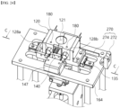
- the position detection means may be a position detection sensor 270 for detecting the positions of the heating blocks 122a, 122b that linearly move in left and right directions through the driving of the driving part 130.
- Such a position detection sensor 270 may be a non-contact position detection sensor.
- the non-contact position detection sensor 270 may be a known photo-microsensor.
- the non-contact position detection sensor 270 may include a photosensor 272 which is installed on one surface of the support 164, and a detection bar 274, one end of which is fixedly installed in the second heat insulating block 124b.
- the photosensor 272 may detect the position of the second heating block 122b through the detection bar 274, and the information detected through the position detection sensor 270 may be provided to the control part 150.
- control part 150 may accurately detect the position of the second heating block 122b through the non-contact position detection sensor 270, and may accurately check the origin of the motor 131.
- the second heat insulating block 124b may move together with the second heating block 122b.
- the detection bar 274 which is fixed to the second heat insulating block 124b, may move toward the photosensor 272, and as illustrated in FIG. 23 , when the second heating block 122b is completely moved to the standby position, a partial length of the detection bar 274 may enter a groove portion that is formed in the photosensor 272.
- control part 150 determines that the second heating block 122b is correctly located in the standby position and controls the driving of the motor 131 such that it is possible to prevent the second heating block 122b from moving excessively.
- the detection bar 274 which is fixed to second heat insulating block 124b, may move away from the photosensor 272.
- FIG. 1 The drawings and description exemplify a non-contact sensor as a method for detecting the position of the second heating block 122b, but the present invention is not limited thereto, and various known position detection sensors may be employed as long as the position of the heating block 122 can be detected.
- the sensing part 140 may check the state of the container 10 disposed in the heating space 121. For example, when the thawing part 120 is located at the heating position, the sensing part 140 may detect the surface temperature of the container 10 that is disposed in the heating space 121, and provide the detected result to the control part 150.
- control part 150 may output information on the container 10 detected through the sensing part 140 at the heating position to the display 118.
- the user may check the thawing process of the biological material contained in the container 10 in real time through the information output from the display 118, and may monitor whether the biological material is thawing within an appropriate temperature range.
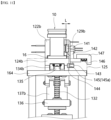
- the sensing part 140 may include a sensor 141 for checking the state of the container 10 disposed in the heating space 121, and a mounting member 142 on which the sensor 141 is mounted.
- the senor 141 may be an infrared temperature sensor to measure the surface temperature of the container 10 in a non-contact manner, and while the sensor 141 is fixed to the mounting member 142, it may measure the surface temperature of the container 10 disposed in the heating space 121.
- the heating blocks 122a, 122b may include placement holes 129a, 129b that are formed in a shape corresponding to the sensor 141 such that the sensor 141 may enter the heating space 121.
- the placement holes 129a, 129b may be formed to pass through the first heating block 122a and the second heating block 122b, respectively, and the placement holes 129a, 129b may be formed by joining a portion 129a that is formed in the first heating block 122a and a portion 129b that is formed in the second heating block 122b.
- the sensor 141 does not come into contact with the container 10 disposed in the heating space 121 through the placement holes 129a, 129b, and may measure the surface temperature of the container 10 at a location very close to the container 10.
- the temperature information measured by the sensor 141 may be used as information for detecting whether the container 10 is disposed in the heating space 121.
- an infrared temperature sensor is exemplified as the sensor 141, but the present invention is not limited thereto, and various known sensors may all be employed, and depending on the type of sensor employed, the information of the container 10 measured may vary.
- the mounting member 142 may be provided to move in forward and backward directions in association with the operation of the power transmission member.
- the mounting member 142 may move in a direction closer to the container 10, and when the first heating block 122a and the second heating block 122b are changed from the heating position to the standby position, the mounting member 142 may move in a direction of moving away from the container 10.
- the sensing part 140 may include a roller member 143 which is rotatably coupled to the mounting member 142, and a contact member 144 which is fixedly coupled to the first heat insulating block 124a, protrudes a certain length in a direction parallel to the moving direction of the first insulation block 124a and is formed with a contact surface 145 with which the roller member 143 comes into contact, and the contact surface 145 may be formed as a flat cam.
- the sensing part 140 may further include an elastic member 146 for pressing the mounting member 142 toward the heating space 121, and a fixture 147 which is coupled to the pedestal 125 so as to support an end of the elastic member 146.
- the pedestal 125 may include a coupling groove 125b which is formed to be drawn from one surface to a certain depth such that a portion of the mounting member 142 can be accommodated, and a moving path 125c of a long hole which is formed through the coupling groove 125b such that the roller member 143 protruding from mounting member 142 can pass through, and the fixture 147 may be coupled to the pedestal 125 so as to cover a portion of the mounting member 142 that is inserted into the coupling groove 125b.
- the mounting member 142 may be pressed toward the contact member 144 through the elastic force provided from the elastic member 146 in a state where a portion thereof is accommodated in the coupling groove 125b, and the roller member 143 may maintain a state of being in contact with the contact surface 145 of the contact member 144, and the roller member 143 may be rotated while one side thereof is in contact with the contact surface 145.
- the contact member 144 which is fixed to the first heat insulating block 124a may slidably move along the guide rail 135 together with the first insulation block 124a, and in the contact surface 145, the position of a portion in contact with the roller member 143 may be changed.
- the contact surface 145 may include a first portion 145a, a second portion 145b and a third portion 145c, and the first portion 145a and the third portion 145c may be connected to each other via the second portion 145b.
- the first portion 145a and the third portion 145c may be formed stepwise from each other, and the third portion 145c may be formed to protrude toward the roller member 43 relatively compared to the first portion 145a.
- the mounting member 142 moves a certain distance (L) in the front and rear directions along the moving path 125c within the coupling groove 125b, it may move in a direction closer to the container 10 or move in a direction away from the container 10 based on the state in which the container 10 is disposed in the heating space 121.
- the user may easily dispose a container 10 on the pedestal 125 or easily remove a container 10 from the pedestal 125 in a state where the first heating block 122a and the second heating block 122b are located at a standby position without being interfered by the sensor 141.
- the control part 150 may control overall driving of the cell thawing machines 100, 200 according to one embodiment of the present invention.
- control part 150 may include a circuit board 151 and a chipset 152 such as an MCU that is mounted on the circuit board 151, and the control part 150 may control all operations of the thawing part 120, the driving part 130, the sensing part 140, the display 118, the manipulation part 117 and the position detection means described above.
- control part 150 may control the driving of the driving part 130 so as to heat the container while the first heating block 122a and the second heating block 122b are in contact with each other, but it may control the driving of the driving part 130 so as to heat the container 10 while the first heating block 122a and the second heating block 122b do not come into contact with each other.
- control part 150 may set the heating position such that a predetermined gap is formed in the remaining portion except for portions where the opposing surfaces 127a, 127b for forming the heating space 121 are formed among the surfaces of the first heating block 122a and the second heating block 122b facing each other.
- the cell thawing machines 100, 200 may prevent a load that may occur in the motor 131 in order to maintain contact between the first heating block 122a and the second heating block 122b at the heating position.
- the cell thawing machines 100, 200 may discharge water vapor or moisture generated from the surface of the container 10 to the outside through the gap. Through this, the biological material contained in the container 10 may be thawed more smoothly.
- control part 150 may start thawing the biological material contained in the container 10.
- control part 150 may maintain the temperatures of the heating blocks 122a, 122b to be constant through PID control, and when the heating blocks 122a, 122b are provided in plurality, the control part 150 may individually control each of the heating blocks 122a, 122b.
- the preheating temperature of the heating blocks 122a, 122b may be the same as the thawing temperature for thawing the biological material contained in the container 10 or may be a relatively higher temperature than the thawing temperature.
- control part 150 may maintain the temperatures of the heating blocks 122a, 122b to be constant while the container 10 which is introduced into the heating space 121 is completely thawed and the heating blocks 122a, 122b are changed to the standby position.
- the cell thawing machines 100, 200 may be changed between the heating position and the standby position while the heating blocks 122a, 122b are continuously maintained at a constant temperature.
- the user may sequentially introduce and remove a plurality of containers 10 into the heating space 121 to perform thawing, thereby minimizing the waiting time increase work productivity.
- the cell thawing machine 200 may conveniently perform qualification evaluation in order to verify the operating temperature of the heating block.
- the cell thawing machine 200 may further include a sensor insertion hole 180, and the sensor insertion hole 180 may be formed to be drawn at a certain depth from one surface of the heating blocks 122a, 122b.
- the sensor insertion hole 180 may be a space into which a calibration sensor is inserted during calibration in order to check whether the heating blocks 122a, 122b are normally operating.
- the calibration sensor (not illustrated) may be a bar-shaped temperature sensor having a predetermined length, and a partial length of the calibration sensor may be inserted into the sensor insertion hole 180.
- the checker may easily measure the temperatures of the heating blocks 122a, 122b through the calibration sensor inserted into the sensor insertion hole 180, it is possible to check whether the cell thawing machines 100, 200 according to one embodiment of the present invention are normally operating.
- the sensor insertion hole 180 may be provided as one, when the heating blocks 122a, 122b include the above-described first heating block 122a and second heating block 122b, it may be provided in plurality so as to be respectively formed in the first heating block 122a and the second heating block 122b.
- the sensor insertion hole 180 may be formed on a side surface of the heating blocks 122a, 122b, but as illustrated in FIG. 18 , the sensor insertion hole 180 may be formed on the heating blocks 122a, 122b to be drawn in at a certain depth from the upper surface to the lower portion of the heating block 122a, 122b.
- the sensor insertion holes 180 formed on the upper surfaces of the heating blocks 122a, 122b may be exposed to the outside.
- the sensor insertion hole 180 for calibration may be exposed to the outside.
- the calibration sensor which is inserted into the sensor insertion hole 180 may maintain a state of being inserted upright into the sensor insertion hole 180 even without a separate fixing means.
- the checker may insert a partial length of the calibration sensor into the sensor insertion hole 180 formed on the upper surface of the heating block 122a, 122b, and then, it is possible to simply and accurately measure the operating temperatures of the heating block 122a, 122b.
- the sensor insertion hole 180 may be formed to be located directly above the temperature sensors 128a, 128b that are embedded in the heating blocks 122a, 122b.
- the sensor insertion hole 180 may be formed in the heating blocks 122a, 122b such that a lower end, which is a sealed end, is located directly above the temperature sensors 128a, 128b, and the lower end of the sensor insertion hole 180 may be formed on the heating block 122a, 122b to have a gap of 1 mm to 5 mm from the temperature sensor 128a, 128b.
- the temperatures of the heating blocks 122a, 122b measured by the calibration sensor inserted into the sensor insertion hole 180 may be similar to the temperatures of the heating blocks 122a, 122b measured by the temperature sensors 128a, 128b, when the cell thawing machines 100, 200 according to one embodiment of the present invention operate.
- the temperatures of the heating blocks 122a, 122b measured through the calibration sensor are similar to the temperatures of the heating blocks 122a, 122b measured by the temperature sensors 128a, 128b during normal operation, and thus, the calibration result may secure high reliability.
- a cover 116 for covering the inlet 115 is removed, and power is supplied to the cell thawing machines 100, 200.
- control part 150 may drive the driving part 130 to change the thawing part 120 to a standby position.
- control part 150 may drive the motor 131 to raise the moving member 136. Accordingly, the first heating block 122a and the second heating block 122b may be slid and moved away from each other, and may be changed to a standby position of being spaced apart from each other at a predetermined interval.
- the preparation step of changing the thawing part 120 to the standby position when power is applied may be omitted.
- the control part 150 operates the first heater 123a and the second heater 123b to preheat the first heating block 122a and the second heating block 122b to a predetermined temperature.
- the preheating temperature of the first heating block 122a and the second heating block 122b may be equal to or relatively higher than the thawing temperature for thawing the biological material contained in the container 10.
- the preheating of the first heating block 122a and the second heating block 122b may be performed in a state where surfaces of the first heating block 122a and the second heating block 122b facing each other are in contact with each other.
- the control part 150 may lower the moving member 136 by driving the motor 131. Accordingly, the first heating block 122a and the second heating block 122b may slid and moved in a direction closer to each other in the standby position, respectively, and they may be changed to a state where surfaces of the first heating block 122a and the second heating block 122b facing each other are in contact with each other.
- control part 150 may control the driving of the motor 131 such that the contact state of the first heating block 122a and the second heating block 122b may be maintained until the preheating of the first heating block 122a and the second heating block 122b is finished.
- the first heating block 122a and the second heating block 122b may be simultaneously heated through a first heater 123a and a second heater 123b that are respectively placed on both sides, and thus, the first heating block 122a and the second heating block 122b may be quickly heated to a predetermined temperature through heat transferred from the first heater 123a and the second heater 123b.
- the control part 150 may output a message indicating that the preheating is completed to the display 118, and the control part 150 may slide and move the first heating block 122a and the second heating block 122b by driving the motor 131.
- the first heating block 122a and the second heating block 122b may be changed to a standby position of being spaced apart from each other at a predetermined interval.
- the user may check the set thawing time through the display 118, and if the set thawing time needs to be changed, the user may manipulate the manipulation part 117 to change the set thawing time to an appropriate time.
- the user may dispose a container 10 that needs to be thawed between the first heating block 122a and the second heating block 122b that are disposed in the standby position.
- the container 10 may be disposed such that a flange part 16 is inserted into the seating groove 125a while the lower surface is seated on one surface of the protruding member 125d.
- the user may input a thawing start signal through the manipulation part 117 in a state where the container 10 that needs to be thawed is placed between the first heating block 122a and the second heating block 122b that are disposed in the standby position.
- control part 150 may heat the container 10 so as to thaw the biological material contained in the container 10 as a second step (S2).
- control part 150 may lower the moving member 136 by driving the motor 131 such that the first heating block 122a and the second heating block 122b can be moved in a direction closer to each other.
- the first heating block 122a and the second heating block 122b may be changed from a standby position to a heating position for forming a heating space 121 for accommodating and heating the container 10, and the circumferential surface of the container 10 may be surrounded by the first heating block 122a and the second heating block 122b in a state where the container 10 is disposed in the heating space 121.
- the sensor 141 may be connected to the linear movement of the first heating block 122a and the second heating block 122b to move toward the placement holes 129a, 129b that are respectively formed on the first heating block 122a and the second heating block 122b such that it is possible to detect the state of the container accommodated in the heating space 121.
- the container 10 may be heated by the thawing time set by the user through the heat transferred from the first heating block 122a and the second heating block 122b, and through the sensor 141, it is possible to measure the state of the container 10 in real time.
- control part 150 may output a message indicating that it is thawing to the display 118, and based on the temperature information transmitted from the first temperature sensor 128a and the second temperature sensor 128b, the temperatures of the first heating block 122a and the second heating block 122b may be maintained to be constant by controlling the operation of the first heater 123a and the second heater 123b, and the state information about the container 10 detected through the sensor 141 may be output to the display 118 through driving of the control part 150.
- the container 10 disposed in the heating space 121 may be heated by the heat transferred from the first heating block 122a and the second heating block 122b in a non-contact manner.
- the circumferential surface of the container 10 may be spaced apart by a predetermined interval from the opposing surface 127a of the first heating block 122a and the opposing surface 127b of the second heating block 122b forming the heating space 121.
- a gap (d) may be formed between the pair of opposing surfaces 127a, 127b and the outer surface of the container 10 in a state where the container 10 is disposed in the heating space 121.
- the heat stored in the first heating block 122a and the second heating block 122b may be transferred to the relatively low-temperature container 10 through convection and/or radiation instead of conduction.
- the circumferential surface of the container 10 may be heated through convective heat and/or radiant heat, the circumferential surface of the container 10 may be uniformly heated by convective heat and/or radiant heat transferred from the heating block 122a, 122b.
- the control part 150 may control the driving of the motor 131 so as to heat the container 10 in a state where the first heating block 122a and the second heating block 122b are in contact with each other, but it may control the driving of the motor 131 so as to heat the container 10 in a state where the first heating block 122a and the second heating block 122b do not contact each other.
- control part 150 may set the heating position such that a predetermined gap is formed in the remaining portion except for portions where the opposing surfaces 127a, 127b for forming the heating space 121 are formed among the surfaces of the first heating block 122a and the second heating block 122b facing each other.
- the cell thawing machines 100, 200 may prevent a load that may occur in the motor in order to maintain the state where the first heating block 122a and the second heating block 122b are in contact with each other in the heating position, and in the process of thawing the biological material contained in the container 10 at the heating position, it is possible to discharge water vapor or moisture generated from the surface of the container 10 to the outside through the gap, and thus, it is possible to thaw the biological material more smoothly.
- the control part 150 may output a message indicating completion to the display 118, and as a third step (S3), the control part 150 may drive the motor 131 to change the first heating block 122a and the second heating block 122b to the standby position.
- the user may remove the container 10 disposed between the first heating block 122a and the second heating block 122b while the first heating block 122a and the second heating block 122a are located in the standby position.
- control part 150 may control the driving of the first heater 123a and the second heater 123b such that the temperatures of the first heating block 122a and the second heating block 122b are continuously maintained to be constant.
- the user may sequentially thaw a plurality of containers 10 by sequentially repeating the first step (S 1) and the second step (S2).
Landscapes
- Health & Medical Sciences (AREA)
- Chemical & Material Sciences (AREA)
- Life Sciences & Earth Sciences (AREA)
- Engineering & Computer Science (AREA)
- Organic Chemistry (AREA)
- Bioinformatics & Cheminformatics (AREA)
- Wood Science & Technology (AREA)
- Zoology (AREA)
- Chemical Kinetics & Catalysis (AREA)
- Clinical Laboratory Science (AREA)
- Biomedical Technology (AREA)
- Genetics & Genomics (AREA)
- Biotechnology (AREA)
- Biochemistry (AREA)
- General Health & Medical Sciences (AREA)
- General Engineering & Computer Science (AREA)
- Molecular Biology (AREA)
- Microbiology (AREA)
- Sustainable Development (AREA)
- Cell Biology (AREA)
- Freezing, Cooling And Drying Of Foods (AREA)
Abstract
Description
- The present invention relates to a cell thawing machine and an operating method thereof.
- In general, various biological materials are stored at low temperature after being stored in containers such as vials. For example, plasma and tissue cells are stored at a maximum of -100 degrees Celsius, and stem cells are stored at cryogenic temperatures of up to -165 degrees Celsius by using gaseous liquid nitrogen.
- These biological materials are tested at a temperature higher than the storage temperature of the aforementioned low-temperature state. Accordingly, a thawing process is required to test the biological material.
- To this end, a cell thawing machine has been proposed for thawing a biological material in a low-temperature state by heating a container such as a vial in which the biological material is stored.
- However, conventional cell thawing machines adopt a method of transferring heat while a heating block and a container are in contact with each other. Accordingly, the conventional cell thawing machines have a problem in that it is difficult to uniformly heat the container as a whole, and since the high-temperature heating block directly contacts the container, there is a problem in that the container is cracked or deformed by the high temperature.
- In addition, the conventional cell thawing machine was a method of simply displaying whether the heating block was operating normally through an indicator such as an LED.
- Accordingly, the conventional cell thawing machines have a problem in that the operating temperature of the heating block cannot be easily measured during qualification evaluation to determine whether the heating block operates correctly.
- The present invention has been devised in view of the above points, and an object of the present invention is to provide a cell thawing machine which is capable of uniformly heating the container as a whole while securing the heat stability of the container including the biological material during the heating process, and an operation method thereof.
- In addition, another object of the present invention is to provide a cell thawing machine which is capable of increasing energy use efficiency and an operating method thereof.
- Moreover, still another object of the present invention is to provide a cell thawing machine which is capable of conveniently measuring the operating temperature of a heating block during qualification evaluation.
- In order to achieve the above-described objects, the present invention provides a cell thawing machine, including a thawing part including a heating block which includes a first heating block and a second heating block that form a heating space for heating a container in which a predetermined amount of biological material including cells is stored, a heater which is installed in the heating block to provide heat to the heating block, a heat insulating block which is coupled to the heating block to surround the heater, and a pedestal which is configured to support a lower portion of the container in the heating space; a driving part for providing a driving force that linearly moves each of the first heating block and the second heating block in left and right directions; a sensing part including a sensor for detecting the state of the container disposed in the heating space, and a mounting member on which the sensor is mounted and which moves in forward and backward directions in connection with the operation of the driving part; and a control part for controlling the operations of the thawing part, the driving part and the sensing part.
- Meanwhile, the present invention provides a method for operating a cell thawing machine including a heating block including a first heating block and a second heating block which form a heating space for heating a container in which a predetermined amount of biological material including cells is stored through linear movement by a driving force of a motor, and heat the container accommodated in the heating space through heat provided from a heater; and a sensor for changing a position in connection with the linear movement of the heating block and detecting the state of the container disposed in the heating space, the method including a first step of preheating the first heating block and the second heating block to a predetermined temperature by driving the heater while one surface of the first heating block and one surface of the second heating block facing each other are in contact with each other; a second step of heating the container disposed in the heating space to thaw the biological material while the first heating block and the second heating block are changed to a heating position forming the heating space; and a third step of changing the first and second heating blocks to a standby position by moving the same in a direction of moving away from the heating position such that the container disposed in the heating space can be removed, wherein in the second step, the container disposed in the heating space is heated by heat transferred from the first heating block and the second heating block in a non-contact manner without contacting the first heating block and the second heating block.
- According to the present invention, the container can be uniformly heated by heating the container in a non-contact heating manner by using radiant heat, and it is possible to prevent cracks or thermal deformation of the container that may occur during heating by conductive heat in advance.
- In addition, according to the present invention, since the temperature of the heating block can be maintained to be constant, a plurality of containers can be sequentially thawed. Through this, the present invention can improve energy consumption efficiency, because it is possible to thaw a plurality of containers while reducing the reuse waiting time for thawing containers.
- Furthermore, according to the present invention, when the upper cover is separated, the sensor insertion hole for qualification evaluation is exposed to the outside such that it is possible to easily perform qualification evaluation.
-
-
FIG. 1 is a view showing a cell thawing machine according to one embodiment of the present invention; -
FIG. 2 is a view ofFIG. 1 viewed from another direction; -
FIG. 3 is a view in which the housing is separated fromFIG. 1 ; -
FIG. 4 is a view showing the cell thawing machine according to the first embodiment of the present invention, showing a state in which the housing and circuit board are removed fromFIG. 3 ; -
FIG. 5 is a view ofFIG. 4 viewed from another direction; -
FIG. 6 is a view in which some components are separated fromFIG. 4 ; -
FIG. 7 is an enlarged view of a part ofFIG. 5 , in which portions of the first heating block and the second heating block are cut in a standby position; -
FIG. 8 is a view showing a portion of the cell thawing machine according to the first embodiment of the present invention in a state where the heating block is disposed in a heating position; -
FIG. 9 is a view showing the configuration of a sensing part applied to the cell thawing machine according to one embodiment of the present invention, showing the position of a roller member in a state where the heating block is disposed at a heating position; -
FIG. 10 is a view showing the configuration of a sensing part applied to the cell thawing machine according to one embodiment of the present invention, showing the position of a roller member in a state where the heating block is placed in a standby position; -
FIG. 11 is a view showing the arrangement relationship of the sensing part, the heating block and the container corresponding to the state ofFIG. 9 , showing a state in which the first heating block, the first heat insulating block and the first guide block are removed; -
FIG. 12 is a view showing the arrangement relationship of the sensing part and the heating block corresponding to the state ofFIG. 10 , showing a state in which the first heating block, the first heat insulating block and the first guide block are removed; -
FIG. 13 is an operating state diagram of the cell thawing machine according to the first embodiment of the present invention, and is a partial cross-sectional view of the standby position at the time of initial operation, as viewed from the A-A direction ofFIG. 8 ; -
FIG. 14 is an operating state diagram showing a state in which the heating block is preheated in the cell thawing machine according to the first embodiment of the present invention, and is a partial cross-sectional view as viewed from the A-A direction ofFIG. 8 ; -
FIG. 15 is an operating state diagram showing the process of loading a container into the cell thawing machine according to the first embodiment of the present invention, and is a partial cross-sectional view as viewed from the A-A direction ofFIG. 8 ; -
FIG. 16 is an operating state diagram of the cell thawing machine according to the first embodiment of the present invention, and is a partial cross-sectional view of a state in which the container is heated in the heating position, as viewed from the A-A direction inFIG. 8 ; -
FIG. 17 is an operating state diagram of the cell thawing machine according to the first embodiment of the present invention, and is a partial cross-sectional view of the process of removing the container from the standby position, as viewed from the A-A direction inFIG. 8 ; -
FIG. 18 is a view showing a cell thawing machine according to the second embodiment of the present invention, showing a state in which the upper cover is separated from the state in which the cover is removed inFIG. 1 ; -
FIG. 19 is a cross-sectional view in the B-B direction ofFIG. 18 , extracting a thawing part; -
FIG. 20 is a view showing the cell thawing machine according to the second embodiment of the present invention, showing a state in which the housing and circuit board are removed fromFIG. 3 ; -
FIG. 21 is a view ofFIG. 20 viewed from another direction; -
FIG. 22 is a view in which some components are separated fromFIG. 20 ; -
FIG. 23 is an enlarged view of a part ofFIG. 21 , in which portions of the first heating block and the second heating block are cut in a standby position; -
FIG. 24 is a view showing a part of the cell thawing machine according to the second embodiment of the present invention in a state where the heating block is disposed at a heating position; -
FIG. 25 is an operating state diagram of the cell thawing machine according to a second embodiment of the present invention, and is a partial cross-sectional view of the standby position when initially driven, as viewed from the B-B direction ofFIG. 24 ; -
FIG. 26 is an operating state diagram showing a state in which the heating block is preheated in the cell thawing machine according to the second embodiment of the present invention, and is a partial cross-sectional view as viewed from the C-C direction ofFIG. 24 ; -
FIG. 27 is an operating state diagram showing the process of loading a container into the cell thawing machine according to the second embodiment of the present invention, and is a partial cross-sectional view as viewed from the C-C direction ofFIG. 24 ; -
FIG. 28 is an operating state diagram of the cell thawing machine according to the second embodiment of the present invention, and is a partial cross-sectional view of the state in which the container is heated in the heating position, as viewed from the direction C-C inFIG. 24 ; -
FIG. 29 is an operating state diagram of the cell thawing machine according to the second embodiment of the present invention, and is a partial cross-sectional view of the process of removing the container from a standby position, as viewed from the C-C direction inFIG. 24 ; and -
FIG. 30 is a block diagram showing the operating method of a cell thawing machine according to one embodiment of the present invention. - Hereinafter, with reference to the accompanying drawings, the exemplary embodiments of the present invention will be described in detail so that those skilled in the art can easily practice the present invention. The present invention may be embodied in many different forms and is not limited to the exemplary embodiments set forth herein. In order to clearly describe the present invention in the drawings, parts that are irrelevant to the description are omitted, and the same reference numerals are assigned to the same or similar components throughout the specification.
- The cell thawing machines 100, 200 according to one embodiment of the present invention may heat and thaw biological materials in a low-temperature state (e.g., frozen state) contained in a
container 10. - Herein, the biological material may include cells, which are the structural basic unit of an organism, and the
container 10 may be a known laboratory container or a container for medical use, such as a vial, a beaker or a test tube. - In addition, as illustrated in
FIG. 1 , thecontainer 10 may include a containermain body 12 in which the biological material is accommodated, acap part 14 for covering an open upper portion of the containermain body 12, and aflange part 16 which is formed to protrude from a lower portion of the containermain body 12, and a biological material of about 2 mL capacity may be contained in the containermain body 12. However, the shape of thecontainer 10 and the capacity of the biological material contained in the containermain body 12 are not limited thereto and may be changed into various shapes depending on design conditions. - In this case, the cell thawing machines 100, 200 according to one embodiment of the present invention may heat the
container 10 uniformly as a whole by heating thecontainer 10 in a non-contact heating manner through radiant heat and/or convection heat, and it is possible to prevent cracks or thermal deformation of thecontainer 10 that may occur during contact heating by conductive heat in advance. - To this end, as illustrated in
FIGS. 1 to 6 and18 to 22 , the cell thawing machines 100, 200 according to one embodiment of the present invention include ahousing 110, athawing part 120, a drivingpart 130, asensing part 140 and acontrol part 150. - As illustrated in
FIGS. 1 to 3 , thehousing 110 may form an outer surface of the cell thawing machine 100, 200, and it may be formed in a box shape such that thethawing part 120, the drivingpart 130, thesensing part 140 and thecontrol part 150 can be disposed therein. - The
housing 110 may be composed of one member or may be composed of a plurality of members, and the plurality of members may be detachably coupled. - For example, as illustrated in
FIG. 3 , thehousing 110 may include a box-shapedmain body 111, alower cover 112 for covering an open lower portion of themain body 111, arear cover 113 for covering an open rear surface of themain body 111, and anupper cover 114 for covering an upper portion of themain body 111. - In this case, the
thawing part 120, the drivingpart 130, thesensing part 140 and thecontrol part 150 may be disposed inside themain body 111. - In this case, the
housing 110 may include aninlet 115 which is formed to penetrate a predetermined area such that thecontainer 10 can be inserted into themain body 111, and theinlet 115 may be covered through acover 116. - Herein, the
inlet 115 may be formed to penetrate thehousing 110 so as to be located at a position corresponding to aheating space 121 to be described below. - For example, the
inlet 115 may be formed to penetrate theupper cover 114 to communicate with aheating space 121 formed in thethawing part 120 at a heating position to be described below. Through this, when thecontainer 10 is inserted into theinlet 115, thecap part 14 of thecontainer 10 may be exposed to the outside through theinlet 115, and the remaining portion except for thecap part 14 may be inserted into theheating space 121. - In addition, as illustrated in
FIGS. 1 and18 , amanipulation part 117 for manipulating the operation of the cell thawing machines 100, 200 according to one embodiment of the present invention, and adisplay 118 for displaying the operating state of the cell thawing machines 100, 200 may be provided on one side of thehousing 110. - Such a
manipulation part 117 may be an interface for transmitting an input signal to thecontrol part 150 through user manipulation. - Herein, the
manipulation part 117 may be configured with a known press-type physical button or capacitive touch button. - In addition, although it may be provided separately from the
display 118, it may be provided in an integrated form with thedisplay 118. - Moreover, the
display 118 may output information on the overall operating state of the cell thawing machines 100, 200 operated through the control part 150 (e.g., the operating status such as the temperature of theheating blocks container 10, thawing or completion of thawing, or thawing progress time), date and time at the time of thawing, an error message such as sensor or heater failure, which will be described below, and the like. - Through this, the user may transmit input signals, such as operation and stop of the cell thawing machines 100, 200, thawing temperature adjustment and thawing time adjustment, to the
control part 150 through manipulation of themanipulation part 117, and thedisplay 118 may output information on the overall state of the cell thawing machines 100, 200 through thecontrol part 150. - Moreover, as illustrated in
FIG. 2 , the cell thawing machines 100, 200 may include at least onecommunication port 119 that is provided to be exposed to the outside from one side of thehousing 110, and thecommunication port 119 may be electrically connected to thecontrol part 150. - For example, the
communication port 119 may include aLAN port 119a for communication with communication equipment such as an external network device or a PC, and aUSB port 119b for inputting or outputting data, and thecommunication port 119 may be mounted on therear cover 113 so as to be electrically connected to thecontrol part 150. - In this case, when the cell thawing machines 100, 200 according to one embodiment of the present invention are connected to the external network device or communication equipment such as a PC through the
communication port 119, thecontrol part 150 may be time-synchronized with communication equipment such as the external network device or PC. - For example, when the cell thawing machines 100, 200 are connected to a PC such as a laptop computer, the cell thawing machines 100, 200 may be synchronized with the date and time of the PC by using a synchronization program installed in the PC.
- Through this, the cell thawing machines 100, 200 according to one embodiment of the present invention may be synchronized with the local time of the region where thawing is performed when in use, and the local time of the region may be output through the
display 118. - As a result, the cell thawing machines 100, 200 according to one embodiment of the present invention may store history information about the exact time of thawing of the biological material contained in the
container 10, and the user may confirm the exact thawing time of the biological material contained in thecontainer 10 through the history information. - Additionally, information related to thawing may be stored in the cell thawing machines 100, 200 themselves or may be stored in a synchronization program of a communication device that is connected through the
communication port 119. - In this case, although the information related to thawing stored in the cell thawing machines 100, 200 or the synchronization program may be stored by date, a thawing history may be stored for each thawing case, and the thawing history may include the local time of the region where the thawing is performed.
- The
thawing part 120 may heat thecontainer 10 while thecontainer 10 introduced into thehousing 110 through theinlet 115 is accommodated in aheating space 121. - To this end, as illustrated in
FIGS. 4 to 8 and20 to 24 , thethawing part 120 may includeheating blocks heating space 121 for accommodating thecontainer 10,heaters heating blocks heating blocks blocks heating blocks heaters pedestal 125 for supporting a lower portion of thecontainer 10 in theheating space 121. - Accordingly, when the
container 10 is introduced into thehousing 110 through theinlet 115, the lower portion of thecontainer 10 may be supported through apedestal 125, and thecontainer 10 may be surrounded through theheating blocks FIGS. 16 ,19 and28 ). - In this case, as illustrated in
FIGS. 6 ,7 ,22 and23 , theheating blocks arrangement grooves heaters arrangement grooves heat insulating blocks heating blocks arrangement grooves heaters arrangement grooves - Herein, the
heating blocks heat insulating blocks - Accordingly, when the
heaters heating blocks heaters heaters heating blocks heat insulating blocks heaters heating blocks heating space 121. - As a result, the
container 10 may be heated by the heat provided from theheating blocks container 10 may be thawed by the heat. - Moreover, since the heat generated from the
heaters heating blocks heat insulating blocks - Additionally, since the
container 10 accommodated in theheating space 121 may be heated by using the heat of theheating blocks heaters container 10 may be heated to a uniform temperature. Herein, the circumferential surface of thecontainer 10 may be the circumferential surface of the containermain body 12 excluding thecap part 14 and theflange part 16. - In this case, as illustrated in
FIGS. 4 and20 , thethawing part 120 may includetemperature sensors heating blocks heating blocks temperature sensors heating blocks temperature sensors control part 150. - Accordingly, the
control part 150 may control the driving of theheaters temperature sensors heating blocks control part 150 may maintain the temperatures of theheating blocks heaters - Moreover, the
control part 150 may prevent overheating of theheating blocks heaters temperature sensors - In the present invention, the
heaters - Meanwhile, the
heating space 121 may be provided in a shape corresponding to the shape of thecontainer 10, and theheating space 121 may be formed through at least twoheating blocks - As a specific example, as illustrated in
FIGS. 4 to 6 and20 to 22 , theheating blocks first heating block 122a and asecond heating block 122b that are disposed such that surfaces thereof face each other, and theheating space 121 may be formed through a pair of opposingsurfaces first heating block 122a and thesecond heating block 122b, respectively. - Herein, the pair of opposing
surfaces container 10. - For example, when the
container 10 is formed in the shape of a cylinder, the pair of opposingsurfaces container 10 is formed in the shape of a square column, the pair of opposingsurfaces - Accordingly, when the
container 10 is introduced into theheating space 121 through theinlet 115, thecontainer 10 may be completely surrounded by a pair of opposingsurfaces heating space 121. - As a result, the circumferential surface of the
container 10 accommodated in theheating space 121 may be uniformly heated by the heat provided from thefirst heating block 122a and thesecond heating block 122b. - In this case, each of the
first heating block 122a and thesecond heating block 122b may includearrangement grooves heaters first heater 123a and asecond heater 123b that are disposed to be inserted into thearrangement groove 126a formed in thefirst heating block 122a and thearrangement groove 126b formed in thesecond heating block 122b, respectively. - In addition, the
heat insulating blocks heat insulating block 124a and a secondheat insulating block 124b, and the firstheat insulating block 124a may be coupled to thefirst heating block 122a so as to completely cover thearrangement groove 126a while thefirst heater 123a is inserted into thearrangement groove 126a of thefirst heating block 122a, and the secondheat insulating block 124b may be coupled to thesecond heating block 122b so as to completely cover thearrangement groove 126b while thesecond heater 123b is inserted into thearrangement groove 126b of thesecond heating block 122b. - Moreover, the
temperature sensors first temperature sensor 128a which is installed in thefirst heating block 122a to measure the temperature of thefirst heating block 122a, and asecond temperature sensor 128b which is installed in thesecond heating block 122b to measure the temperature of thesecond heating block 122b. - Accordingly, the heat generated from the
first heater 123a may heat thefirst heating block 122a, and the heat generated from thesecond heater 123b may heat thesecond heating block 122b, and thecontrol part 150 may control the driving of thefirst heater 123a and thesecond heater 123b based on the temperature information measured by thefirst temperature sensor 128a and thesecond temperature sensor 128b such that it is possible to maintain the temperatures of thefirst heating block 122a and thesecond heating block 122b to be constant. - In this case, the
control part 150 may control the operations of thefirst heater 123a and thesecond heater 123b together based on the temperature information measured through thefirst temperature sensor 128a and thesecond temperature sensor 128b, or thecontrol part 150 may individually control the operations of thefirst heater 123a and thesecond heater 123b based on the temperature information measured through thefirst temperature sensor 128a and thesecond temperature sensor 128b. - Through this, even if the
heating blocks first heating block 122a and thesecond heating block 122b in the cell thawing machines 100, 200 according to one embodiment of the present invention, the temperatures of thefirst heating block 122a and thesecond heating block 122b may be precisely controlled through the control of thecontrol part 150. - Accordingly, since the
first heating block 122a and thesecond heating block 122b may be maintained at the same temperature without temperature deviation through thecontrol part 150, the circumferential surface of thecontainer 10 may be uniformly heated. - Moreover, when the
control part 150 individually controls the driving of thefirst heater 123a and thesecond heater 123b, the user may immediately check an anomaly of the corresponding part based on the information output through thedisplay 118, and take appropriate action on the corresponding part in which the abnormality occurred. - For example, when any one of the
heaters first heating block 122a and thesecond heating block 122b or any one of thetemperature sensors first heating block 122a and thesecond heating block 122b does not operate normally, the user may immediately check an abnormality of the corresponding part based on the information output through thedisplay 118, and take appropriate action on the corresponding part in which the abnormality has occurred. - Meanwhile, in the cell thawing machines 100, 200 according to one embodiment of the present invention, while the
container 10 accommodated in theheating space 121 does not contact theheating block container 10 may be heated by the heat transferred from the heating block 122a., 122b in a non-contact manner. - For example, while the
container 10 is inserted into theheating space 121, the circumferential surface of thecontainer 10 may be spaced apart by a certain interval from the opposingsurface 127a of thefirst heating block 122a and the opposingsurface 127b of thesecond heating block 122b forming theheating space 121. - That is, as illustrated in
FIGS. 16 and28 , while thecontainer 10 is inserted into theheating space 121 and the lower portion of thecontainer 10 is supported through thepedestal 125, a gap (d) may be formed between the pair of opposingsurfaces container 10. - Accordingly, the heat stored in the
first heating block 122a and thesecond heating block 122b may be transferred to the relatively low-temperature container 10 through convection and/or radiation instead of conduction. - As a result, since the cell thawing machines 100, 200 according to one embodiment of the present invention may heat the circumferential surface of the
container 10 through heat transfer using convection and/or radiation, the circumferential surface of thecontainer 10 may be uniformly heated through convective heat and/or radiant heat transmitted from theheating blocks - That is, compared to the case where the
container 10 and theheating blocks container 10 is heated through conduction heat, the cell thawing machines 100, 200 according to one embodiment of the present invention may uniformly heat the circumferential surface of the container through convective heat and/or radiant heat, and thus, it is possible to prevent the concentration of heat in a local location of thecontainer 10. - Moreover, in the cell thawing machines 100, 200 according to one embodiment of the present invention, even if the
container 10 is made of a glass or plastic material that is vulnerable to high-temperature heat, thefirst heating block 122a and thesecond heating block 122b do not come into direct contact with thecontainer 10, and thus, it is possible to prevent cracks or thermal deformation of the container that may occur due to heat when in direct contact with a high-temperature obj ect. - In the present invention, the gap (d) between the pair of opposing
surfaces heating space 121 and the outer surface of thecontainer 10 may be 0.2 mm to 0.3 mm, but the present invention is limited thereto, and the size of the gap (d) may be appropriately changed depending on the overall size of thecontainer 10. - In this case, at least any one of the
first heating block 122a and thesecond heating block 122b may be linearly moved reciprocally in a straight line, and theheating space 121 may be formed when thefirst heating block 122a and thesecond heating block 122b are disposed to be located in nearby positions through the linear movement of at least any one of thefirst heating block 122a and thesecond heating block 122b. The detailed description thereof will be described below. - Meanwhile, as illustrated in
FIGS. 6 ,7 ,22 and23 , thepedestal 125 for supporting a lower portion of thecontainer 10 may include aseating groove 125a which is formed on one surface supporting a lower portion of thecontainer 10 in order to allow a lower edge of thecontainer 10 to be inserted, and a protrudingmember 125d which is formed to protrude at a certain height such that the lower surface of thecontainer 10 can be spaced apart at a certain height from one surface of thepedestal 125. - When the
container 10 is inserted into theinlet 115, theseating groove 125a may stably support thecontainer 10 by fixing the lower edge of thecontainer 10. - In addition, when the
container 10 is inserted into theinlet 115, the protrudingmember 125d may support the lower surface of thecontainer 10 such that the lower surface of thecontainer 10 is spaced apart at a certain height from one surface of thepedestal 125. - To this end, the
seating groove 125a may be formed in a shape corresponding to aflange part 16 such that theflange part 16 formed along the lower edge of thecontainer 10 can be inserted therein, and as illustrated inFIGS. 9 and 10 , theseating groove 125a may be formed to be located outside the protrudingmember 125d along the circumferential direction of the protrudingmember 125d. - Accordingly, when the
container 10 is inserted into theinlet 115, the lower surface of thecontainer 10 may be supported by one surface of the protrudingmember 125d, and theflange part 16 may be inserted into theseating groove 125a, and thecontainer 10 in which theflange part 16 is inserted into theseating groove 125a may maintain an upright state without tilting in any direction. - As a result, while the
container 10 disposed in theheating space 121 is correctly positioned such that the circumferential surface thereof faces a pair of opposingsurfaces heating space 121 in theheating space 121, it may maintain a uniform gap with the pair of opposingsurfaces - The driving
part 130 may linearly move theheating blocks heating blocks first heating block 122a and asecond heating block 122b, the drivingpart 130 may linearly move at least any one of thefirst heating block 122a and thesecond heating block 122b reciprocally in the left and right directions. - As a non-limiting example, when the
heating blocks first heating block 122a and asecond heating block 122b, the drivingpart 130 may linearly move thefirst heating block 122a and thesecond heating block 122b reciprocally in the left and right directions, respectively. - Through this, as illustrated in
FIGS. 16 ,26 and28 , the cell thawing machines 100, 200 according to one embodiment of the present invention may be changed to a heating position in which thefirst heating block 122a and thefirst heating block 122a are disposed to be close to each other through the driving of the drivingpart 130, and a standby position in which thefirst heating block 122a and thesecond heating block 122b are disposed to be spaced apart from each other at a gap through the driving of the drivingpart 130 as illustrated inFIGS. 13 ,15 ,17 ,25 ,27 and29 . - Accordingly, as illustrated in
FIGS. 16 and28 , when thefirst heating block 122a and thesecond heating block 122b are located at the heating position, aheating space 121 for accommodating thecontainer 10 to heat thecontainer 10 may be formed between the opposingsurface 127a of thefirst heating block 122a and the opposingsurface 127b of thesecond heating block 122b. - In addition, as illustrated in
FIGS. 15 ,17 ,27 and29 , when thefirst heating block 122a and thesecond heating block 122b are located in the standby position, a gap between the opposingsurface 127a of thefirst heating block 122a and the opposingsurface 127b of thesecond heating block 122b may be widened. Through this, the user may easily introduce thecontainer 10 to be disposed between thefirst heating block 122a and thesecond heating block 122b or may easily remove thecontainer 10 which is disposed between thefirst heating block 122a and thesecond heating block 122b. - To this end, as illustrated in
FIGS. 4 to 6 and20 to 22 , the drivingpart 130 may include amotor 131 for providing a driving force, a rotatingmember 132 which is axially coupled to arotating shaft 131a of themotor 131, and a power transmission member for interconnecting the rotatingmember 132 and thethawing part 120 so as to linearly move thefirst heating block 122a and thesecond heating block 122b, respectively, when themotor 131 is driven. - In addition, the power transmission member may include
guide blocks heat insulating blocks guide rails 135 for guiding linear movement of theguide blocks member 136 which moves up and down in the top and down directions along the rotatingmember 132 when themotor 131 is driven, andlink members guide blocks member 136 to each other. - As a specific example, the
guide blocks first guide block 134a which is fixedly coupled to the firstheat insulating block 124a and asecond guide block 134b which is fixedly coupled to the secondheat insulating block 124b, thefirst guide block 134a and thesecond guide block 134b may be coupled to theguide rail 135 so as to be slidably movable. - In addition, the
link members first link member 137a for linking the movingmember 136 and thefirst guide block 134a to each other, and asecond link member 137b for linking the movingmember 136 and thesecond link member 137b to each other. - In this case, the cell thawing machines 100, 200 according to one embodiment of the present invention may further include a
base 161, a mounting table 162, asupport bar 163 and asupport 164 that are disposed inside thehousing 110. - That is, as illustrated in
FIGS. 6 and22 , a mounting table 162 may be fixedly coupled to an upper surface of thebase 161, and themotor 131 may be fixedly coupled to one side of the mounting table 162 via acoupling base 165, and the rotatingmember 132 which is axially coupled to arotating shaft 131a of themotor 131 may be rotatably coupled to the mounting table 162. - In addition, the plate-shaped
support 164 having a predetermined area may be disposed at a certain interval from an upper portion from the base 161 through at least onesupport bar 163 having a predetermined length and one end of which is fixedly coupled to thebase 161, and theguide rail 135 and thepedestal 125 may be fixedly coupled to one surface of asupport 164. - Moreover, the
first guide block 134a and thesecond guide block 134b may be slidably coupled to theguide rail 135, and the firstheat insulating block 124a may be fixedly coupled to thefirst guide block 134a, and the secondheat insulating block 124b may be fixedly coupled to thesecond guide block 134b. - Herein, the rotating
member 132 may be a screw bar having a predetermined length and having one end axially coupled to arotating shaft 131a of themotor 131, and the movingmember 136 may be screw-coupled to the rotatingmember 132 to be movable. - In addition, the
support 164 may include a through-hole 164a having a long hole through which thefirst link member 137a and thesecond link member 137b may respectively pass. - Moreover, both ends of the
first link member 137a may be linked to the rotatingmember 132 and thefirst guide block 134a, respectively, and both ends of thesecond link member 137b may be linked to the rotatingmember 132 and thesecond guide block 134b, respectively. - Accordingly, as illustrated in
FIGS. 13 to 17 and25 to 29 , when the rotatingmember 132 which is axially coupled to therotating shaft 131a rotates when themotor 131 is driven, the movingmember 136 may move up and down by screw movement along the rotatingmember 132, and thefirst guide block 134a and thesecond guide block 134b which are respectively linked to the movingmember 136 may be linearly moved in the left and right directions along theguide rail 135 through the ascending and descending of the movingmember 136. - As a result, the first
heat insulating block 124a and the secondheat insulating block 124b, which are fixedly coupled to thefirst guide block 134a and thesecond guide block 134b, respectively, may be linearly moved in the left and right directions in the same manner as thefirst guide block 134a and thesecond guide block 134b, and thefirst heating block 122a and thesecond heating block 122b, which are fixedly coupled to the firstheat insulating block 124a and the secondheat insulating block 124b, respectively, may also be linearly moved in the left and right directions. - Through this, in the cell thawing machines 100, 200 according to one embodiment of the present invention, the
first heating block 122a and thesecond heating block 122b may be changed to a heating position in which thefirst heating block 122a and thesecond heating block 122b are disposed to be close to each other through the driving of the drivingpart 130, and may be changed to a standby position in which thefirst heating block 122a and thesecond heating block 122b are disposed to be spaced apart from each other at an interval through the driving of the drivingpart 130. - Moreover, when the cell thawing machines 100, 200 according to one embodiment of the present invention are changed from the standby position to the heating position through the control of the
control part 150, a lower portion of thecontainer 10, which is accommodated in theheating space 121, may be located at a relatively higher position than the lower surfaces of thefirst heating block 122a and thesecond heating block 122b through the protrudingmember 125d. - Accordingly, the
container 10 which is disposed in theheating space 121 may be disposed in a state where the circumferential surface faces a pair of opposingsurfaces heating space 121. - The drawings and description illustrate and describe that the rotational movement of the
motor 131 is changed to the linear movement of thefirst guide block 134a and thesecond guide block 134b through mutual coupling of the rotatingmember 132, the movingmember 136 and thelink members - In this case, the cell thawing machines 100, 200 according to one embodiment of the present invention may further include a position detecting means for detecting the positions of the
heating blocks - For example, in the cell thawing machine 100 according to one embodiment of the present invention, the position detecting means may be a
limit switch 170 for detecting the positions of theheating blocks heat insulating blocks - As illustrated in
FIG. 6 , thelimit switch 170 may be installed on one surface of thesupport 164, and may detect the position of thesecond heating block 122b through contact with the secondheat insulating block 124b, and the information detected through thelimit switch 170 may be provided to thecontrol part 150. - As a specific example, as illustrated in
FIGS. 7 and8 , thelimit switch 170 may include aswitch box 171 which is fixedly installed on one surface of thesupport 164, an operatinglever 172 which performs a hinge operation on one side of theswitch box 171, and aroller 173 which is rotatably coupled to one end of the operatinglever 172. - Accordingly, in the
limit switch 170, when theroller 173 contacts the secondheat insulating block 124b and the operatinglever 172 operates, theswitch box 171 may be operated, and information on whether theswitch box 171 is operated may be transmitted to thecontrol part 150. - Specifically, as described above, when the
first heating block 122a and thesecond heating block 122b are changed from the heating position to the standby position through the driving of the drivingpart 130, the secondheat insulating block 124b may move together with thesecond heating block 122b. - Through this, the second
heat insulating block 124b may come into contact with theroller 173, and as illustrated inFIG. 7 , when thesecond heating block 122b is completely moved to the standby position, the operatinglever 172 may be operated such that theswitch box 171 can be operated. - In this case, the
control part 150 determines that thesecond heating block 122b is positioned in the standby position and controls the driving of themotor 131 such that it is possible to prevent thesecond heating block 122b from moving excessively. - In addition, as illustrated in
FIG. 8 , when thefirst heating block 122a and thesecond heating block 122b are changed from the standby position to the heating position through the driving of the drivingpart 130, the secondheat insulating block 124b is moved together with thesecond heating block 122b such that the contact state between the secondheat insulating block 124b and theroller 173 can be released. - The drawings and description exemplify a hinge roller-type limit switch as a position detection means for detecting the position of the
second heating block 122b, but the present invention is not limited thereto, and various known limit switches, such as lever-type limit switches and pin-type limit switches, may all be employed. - As another example, in the cell thawing machine 200 according to one embodiment of the present invention, the position detection means may be a
position detection sensor 270 for detecting the positions of theheating blocks part 130. - Such a
position detection sensor 270 may be a non-contact position detection sensor. - As a specific example, the non-contact
position detection sensor 270 may be a known photo-microsensor. As a non-limiting example, as illustrated inFIGS. 20 to 21 , the non-contactposition detection sensor 270 may include a photosensor 272 which is installed on one surface of thesupport 164, and adetection bar 274, one end of which is fixedly installed in the secondheat insulating block 124b. - Accordingly, when the
detection bar 274 approaches thephotosensor 272 through linear movement of thesecond heating block 122b and the secondheat insulating block 124b, thephotosensor 272 may detect the position of thesecond heating block 122b through thedetection bar 274, and the information detected through theposition detection sensor 270 may be provided to thecontrol part 150. - As a result, the
control part 150 may accurately detect the position of thesecond heating block 122b through the non-contactposition detection sensor 270, and may accurately check the origin of themotor 131. - Specifically, as described above, when the
first heating block 122a and thesecond heating block 122b are changed from the heating position to the standby position through the driving of the drivingpart 130, the secondheat insulating block 124b may move together with thesecond heating block 122b. - Through this, the
detection bar 274, which is fixed to the secondheat insulating block 124b, may move toward thephotosensor 272, and as illustrated inFIG. 23 , when thesecond heating block 122b is completely moved to the standby position, a partial length of thedetection bar 274 may enter a groove portion that is formed in thephotosensor 272. - In this case, the
control part 150 determines that thesecond heating block 122b is correctly located in the standby position and controls the driving of themotor 131 such that it is possible to prevent thesecond heating block 122b from moving excessively. - In addition, as illustrated in
FIG. 24 , when thefirst heating block 122a and thesecond heating block 122b are changed from the standby position to the heating position through the driving of the drivingpart 130, thedetection bar 274, which is fixed to secondheat insulating block 124b, may move away from thephotosensor 272. - The drawings and description exemplify a non-contact sensor as a method for detecting the position of the
second heating block 122b, but the present invention is not limited thereto, and various known position detection sensors may be employed as long as the position of the heating block 122 can be detected. - The
sensing part 140 may check the state of thecontainer 10 disposed in theheating space 121. For example, when thethawing part 120 is located at the heating position, thesensing part 140 may detect the surface temperature of thecontainer 10 that is disposed in theheating space 121, and provide the detected result to thecontrol part 150. - Accordingly, the
control part 150 may output information on thecontainer 10 detected through thesensing part 140 at the heating position to thedisplay 118. - As a result, the user may check the thawing process of the biological material contained in the
container 10 in real time through the information output from thedisplay 118, and may monitor whether the biological material is thawing within an appropriate temperature range. - To this end, as illustrated in
FIGS. 6 ,7 ,22 and23 , thesensing part 140 may include asensor 141 for checking the state of thecontainer 10 disposed in theheating space 121, and a mountingmember 142 on which thesensor 141 is mounted. - In this case, the
sensor 141 may be an infrared temperature sensor to measure the surface temperature of thecontainer 10 in a non-contact manner, and while thesensor 141 is fixed to the mountingmember 142, it may measure the surface temperature of thecontainer 10 disposed in theheating space 121. - In addition, the
heating blocks placement holes sensor 141 such that thesensor 141 may enter theheating space 121. - That is, the
placement holes first heating block 122a and thesecond heating block 122b, respectively, and theplacement holes portion 129a that is formed in thefirst heating block 122a and aportion 129b that is formed in thesecond heating block 122b. - Accordingly, when the
thawing part 120 is located at the heating position, thesensor 141 does not come into contact with thecontainer 10 disposed in theheating space 121 through theplacement holes container 10 at a location very close to thecontainer 10. - Moreover, the temperature information measured by the
sensor 141 may be used as information for detecting whether thecontainer 10 is disposed in theheating space 121. - In the above description, an infrared temperature sensor is exemplified as the
sensor 141, but the present invention is not limited thereto, and various known sensors may all be employed, and depending on the type of sensor employed, the information of thecontainer 10 measured may vary. - Meanwhile, when the
motor 131 is driven, the mountingmember 142 may be provided to move in forward and backward directions in association with the operation of the power transmission member. - That is, when the
first heating block 122a and thesecond heating block 122b are changed from the standby position to the heating position based on the state in which thecontainer 10 is disposed in theheating space 121, the mountingmember 142 may move in a direction closer to thecontainer 10, and when thefirst heating block 122a and thesecond heating block 122b are changed from the heating position to the standby position, the mountingmember 142 may move in a direction of moving away from thecontainer 10. - To this end, as illustrated in
FIGS. 6 ,9 to12 and 22 , thesensing part 140 may include aroller member 143 which is rotatably coupled to the mountingmember 142, and acontact member 144 which is fixedly coupled to the firstheat insulating block 124a, protrudes a certain length in a direction parallel to the moving direction of thefirst insulation block 124a and is formed with acontact surface 145 with which theroller member 143 comes into contact, and thecontact surface 145 may be formed as a flat cam. - In addition, as illustrated in
FIGS. 9 and 10 , thesensing part 140 may further include anelastic member 146 for pressing the mountingmember 142 toward theheating space 121, and afixture 147 which is coupled to thepedestal 125 so as to support an end of theelastic member 146. - In this case, as illustrated in
FIGS. 6 and22 , thepedestal 125 may include acoupling groove 125b which is formed to be drawn from one surface to a certain depth such that a portion of the mountingmember 142 can be accommodated, and a movingpath 125c of a long hole which is formed through thecoupling groove 125b such that theroller member 143 protruding from mountingmember 142 can pass through, and thefixture 147 may be coupled to thepedestal 125 so as to cover a portion of the mountingmember 142 that is inserted into thecoupling groove 125b. - Accordingly, the mounting
member 142 may be pressed toward thecontact member 144 through the elastic force provided from theelastic member 146 in a state where a portion thereof is accommodated in thecoupling groove 125b, and theroller member 143 may maintain a state of being in contact with thecontact surface 145 of thecontact member 144, and theroller member 143 may be rotated while one side thereof is in contact with thecontact surface 145. - As a result, as described above, when the
first guide block 134a to which the firstheat insulating block 124a is fixed is slidably moved along theguide rail 135, thecontact member 144 which is fixed to the firstheat insulating block 124a may slidably move along theguide rail 135 together with thefirst insulation block 124a, and in thecontact surface 145, the position of a portion in contact with theroller member 143 may be changed. - That is, as illustrated in the enlarged views of
FIGS. 6 and22 , thecontact surface 145 may include afirst portion 145a, asecond portion 145b and athird portion 145c, and thefirst portion 145a and thethird portion 145c may be connected to each other via thesecond portion 145b. In this case, thefirst portion 145a and thethird portion 145c may be formed stepwise from each other, and thethird portion 145c may be formed to protrude toward the roller member 43 relatively compared to thefirst portion 145a. - Accordingly, when the
contact member 144 which is fixedly installed on the firstheat insulating block 124a is slidably moved along theguide rail 135 together with the firstheat insulating block 124a, as illustrated inFIGS. 9 and 10 , a portion of theroller member 143 which is in contact with thecontact surface 145 may be changed from thefirst portion 145a to thethird portion 145c or from thethird portion 145c to thefirst portion 145a. - As a result, as illustrated in
FIGS. 11 and12 , as the mountingmember 142 moves a certain distance (L) in the front and rear directions along the movingpath 125c within thecoupling groove 125b, it may move in a direction closer to thecontainer 10 or move in a direction away from thecontainer 10 based on the state in which thecontainer 10 is disposed in theheating space 121. - Accordingly, as illustrated in
FIG. 1 , even if thecontainer 10 includes aflange part 16 protruding from the containermain body 12, the user may easily dispose acontainer 10 on thepedestal 125 or easily remove acontainer 10 from thepedestal 125 in a state where thefirst heating block 122a and thesecond heating block 122b are located at a standby position without being interfered by thesensor 141. - The
control part 150 may control overall driving of the cell thawing machines 100, 200 according to one embodiment of the present invention. - As illustrated in
FIG. 3 , thecontrol part 150 may include acircuit board 151 and achipset 152 such as an MCU that is mounted on thecircuit board 151, and thecontrol part 150 may control all operations of thethawing part 120, the drivingpart 130, thesensing part 140, thedisplay 118, themanipulation part 117 and the position detection means described above. - In this case, when heating the
container 10 accommodated in theheating space 121 at the heating position, thecontrol part 150 may control the driving of the drivingpart 130 so as to heat the container while thefirst heating block 122a and thesecond heating block 122b are in contact with each other, but it may control the driving of the drivingpart 130 so as to heat thecontainer 10 while thefirst heating block 122a and thesecond heating block 122b do not come into contact with each other. - That is, the
control part 150 may set the heating position such that a predetermined gap is formed in the remaining portion except for portions where the opposingsurfaces heating space 121 are formed among the surfaces of thefirst heating block 122a and thesecond heating block 122b facing each other. - Through this, the cell thawing machines 100, 200 according to one embodiment of the present invention may prevent a load that may occur in the
motor 131 in order to maintain contact between thefirst heating block 122a and thesecond heating block 122b at the heating position. - Additionally, in the process of thawing the biological material contained in the
container 10 at the heating position, the cell thawing machines 100, 200 according to one embodiment of the present invention may discharge water vapor or moisture generated from the surface of thecontainer 10 to the outside through the gap. Through this, the biological material contained in thecontainer 10 may be thawed more smoothly. - Moreover, after preheating the
heating blocks heaters control part 150 may start thawing the biological material contained in thecontainer 10. - As described above, the
control part 150 may maintain the temperatures of theheating blocks heating blocks control part 150 may individually control each of theheating blocks - Herein, the preheating temperature of the
heating blocks container 10 or may be a relatively higher temperature than the thawing temperature. - In addition, the
control part 150 may maintain the temperatures of theheating blocks container 10 which is introduced into theheating space 121 is completely thawed and theheating blocks - Through this, the cell thawing machines 100, 200 according to one embodiment of the present invention may be changed between the heating position and the standby position while the
heating blocks - Accordingly, when the cell thawing machines 100, 200 according to one embodiment of the present invention are used, the user may sequentially introduce and remove a plurality of
containers 10 into theheating space 121 to perform thawing, thereby minimizing the waiting time increase work productivity. - Meanwhile, the cell thawing machine 200 according to one embodiment of the present invention may conveniently perform qualification evaluation in order to verify the operating temperature of the heating block.
- To this end, the cell thawing machine 200 according to one embodiment of the present invention may further include a
sensor insertion hole 180, and thesensor insertion hole 180 may be formed to be drawn at a certain depth from one surface of theheating blocks - The
sensor insertion hole 180 may be a space into which a calibration sensor is inserted during calibration in order to check whether theheating blocks - For example, the calibration sensor (not illustrated) may be a bar-shaped temperature sensor having a predetermined length, and a partial length of the calibration sensor may be inserted into the
sensor insertion hole 180. - Accordingly, since the checker may easily measure the temperatures of the
heating blocks sensor insertion hole 180, it is possible to check whether the cell thawing machines 100, 200 according to one embodiment of the present invention are normally operating. - Although the
sensor insertion hole 180 may be provided as one, when theheating blocks first heating block 122a andsecond heating block 122b, it may be provided in plurality so as to be respectively formed in thefirst heating block 122a and thesecond heating block 122b. - In this case, the
sensor insertion hole 180 may be formed on a side surface of theheating blocks FIG. 18 , thesensor insertion hole 180 may be formed on theheating blocks heating block - Accordingly, when the
upper cover 114 on which theinlet 115 is formed is separated from thehousing 110, the sensor insertion holes 180 formed on the upper surfaces of theheating blocks - As a result, even if only the
upper cover 114 is separated from thehousing 110 without the need to separate the entire housing in the cell thawing machines 100, 200 according to one embodiment of the present invention, thesensor insertion hole 180 for calibration may be exposed to the outside. - Additionally, in the cell thawing machine 200 according to one embodiment of the present invention, since the
sensor insertion hole 180 is formed to be drawn at a certain depth from the upper surface to the lower portion of theheating block sensor insertion hole 180 may maintain a state of being inserted upright into thesensor insertion hole 180 even without a separate fixing means. - Through this, after separating the
upper cover 114, the checker may insert a partial length of the calibration sensor into thesensor insertion hole 180 formed on the upper surface of theheating block heating block - In this case, the
sensor insertion hole 180 may be formed to be located directly above thetemperature sensors heating blocks - For example, as illustrated in
FIG. 19 , thesensor insertion hole 180 may be formed in theheating blocks temperature sensors sensor insertion hole 180 may be formed on theheating block temperature sensor - Accordingly, during calibration, the temperatures of the
heating blocks sensor insertion hole 180 may be similar to the temperatures of theheating blocks temperature sensors - As a result, when calibration of the cell thawing machine 200 according to one embodiment of the present invention is performed by using the
sensor insertion hole 180, the temperatures of theheating blocks heating blocks temperature sensors - Hereinafter, the method for operating the above-described cell thawing machines 100, 200 will be described with reference to
FIGS. 13 to 17 and25 to 30 . - First of all, as a preparation step, a
cover 116 for covering theinlet 115 is removed, and power is supplied to the cell thawing machines 100, 200. - When power is applied to the cell thawing machines 100, 200, the
control part 150 may drive the drivingpart 130 to change thethawing part 120 to a standby position. - That is, as illustrated in
FIGS. 13 and25 , thecontrol part 150 may drive themotor 131 to raise the movingmember 136. Accordingly, thefirst heating block 122a and thesecond heating block 122b may be slid and moved away from each other, and may be changed to a standby position of being spaced apart from each other at a predetermined interval. - If the
first heating block 122a and thesecond heating block 122b are located in the standby position, the preparation step of changing thethawing part 120 to the standby position when power is applied may be omitted. - Next, as a first step (S1), the
control part 150 operates thefirst heater 123a and thesecond heater 123b to preheat thefirst heating block 122a and thesecond heating block 122b to a predetermined temperature. - For example, the preheating temperature of the
first heating block 122a and thesecond heating block 122b may be equal to or relatively higher than the thawing temperature for thawing the biological material contained in thecontainer 10. - In this case, the preheating of the
first heating block 122a and thesecond heating block 122b may be performed in a state where surfaces of thefirst heating block 122a and thesecond heating block 122b facing each other are in contact with each other. - That is, as illustrated in
FIGS. 14 and26 , thecontrol part 150 may lower the movingmember 136 by driving themotor 131. Accordingly, thefirst heating block 122a and thesecond heating block 122b may slid and moved in a direction closer to each other in the standby position, respectively, and they may be changed to a state where surfaces of thefirst heating block 122a and thesecond heating block 122b facing each other are in contact with each other. - In this state, the
control part 150 may control the driving of themotor 131 such that the contact state of thefirst heating block 122a and thesecond heating block 122b may be maintained until the preheating of thefirst heating block 122a and thesecond heating block 122b is finished. - Accordingly, while the
first heating block 122a and thesecond heating block 122b are in contact with each other, thefirst heating block 122a and thesecond heating block 122b may be simultaneously heated through afirst heater 123a and asecond heater 123b that are respectively placed on both sides, and thus, thefirst heating block 122a and thesecond heating block 122b may be quickly heated to a predetermined temperature through heat transferred from thefirst heater 123a and thesecond heater 123b. - Thereafter, when the preheating of the
first heating block 122a and thesecond heating block 122b is completed, thecontrol part 150 may output a message indicating that the preheating is completed to thedisplay 118, and thecontrol part 150 may slide and move thefirst heating block 122a and thesecond heating block 122b by driving themotor 131. Through this, as illustrated inFIG. 15 , thefirst heating block 122a and thesecond heating block 122b may be changed to a standby position of being spaced apart from each other at a predetermined interval. - In this way, when the preheating of the
first heating block 122a and thesecond heating block 122b is completed, the user may check the set thawing time through thedisplay 118, and if the set thawing time needs to be changed, the user may manipulate themanipulation part 117 to change the set thawing time to an appropriate time. - Next, as illustrated in
FIGS. 15 and27 , in a state where thefirst heating block 122a and thesecond heating block 122b are located in the standby position, the user may dispose acontainer 10 that needs to be thawed between thefirst heating block 122a and thesecond heating block 122b that are disposed in the standby position. In this case, thecontainer 10 may be disposed such that aflange part 16 is inserted into theseating groove 125a while the lower surface is seated on one surface of the protrudingmember 125d. - Thereafter, the user may input a thawing start signal through the
manipulation part 117 in a state where thecontainer 10 that needs to be thawed is placed between thefirst heating block 122a and thesecond heating block 122b that are disposed in the standby position. - Accordingly, the
control part 150 may heat thecontainer 10 so as to thaw the biological material contained in thecontainer 10 as a second step (S2). - That is, the
control part 150 may lower the movingmember 136 by driving themotor 131 such that thefirst heating block 122a and thesecond heating block 122b can be moved in a direction closer to each other. - Accordingly, as illustrated in
FIGS. 16 and28 , thefirst heating block 122a and thesecond heating block 122b may be changed from a standby position to a heating position for forming aheating space 121 for accommodating and heating thecontainer 10, and the circumferential surface of thecontainer 10 may be surrounded by thefirst heating block 122a and thesecond heating block 122b in a state where thecontainer 10 is disposed in theheating space 121. - In addition, as described above, the
sensor 141 may be connected to the linear movement of thefirst heating block 122a and thesecond heating block 122b to move toward theplacement holes first heating block 122a and thesecond heating block 122b such that it is possible to detect the state of the container accommodated in theheating space 121. - Through this, the
container 10 may be heated by the thawing time set by the user through the heat transferred from thefirst heating block 122a and thesecond heating block 122b, and through thesensor 141, it is possible to measure the state of thecontainer 10 in real time. - In this case, the
control part 150 may output a message indicating that it is thawing to thedisplay 118, and based on the temperature information transmitted from thefirst temperature sensor 128a and thesecond temperature sensor 128b, the temperatures of thefirst heating block 122a and thesecond heating block 122b may be maintained to be constant by controlling the operation of thefirst heater 123a and thesecond heater 123b, and the state information about thecontainer 10 detected through thesensor 141 may be output to thedisplay 118 through driving of thecontrol part 150. - In this case, as described above, while the
container 10 disposed in theheating space 121 is not in contact with thefirst heating block 122a and thesecond heating block 122b, it may be heated by the heat transferred from thefirst heating block 122a and thesecond heating block 122b in a non-contact manner. - That is, while the
container 10 is inserted into theheating space 121, the circumferential surface of thecontainer 10 may be spaced apart by a predetermined interval from the opposingsurface 127a of thefirst heating block 122a and the opposingsurface 127b of thesecond heating block 122b forming theheating space 121. - Through this, a gap (d) may be formed between the pair of opposing
surfaces container 10 in a state where thecontainer 10 is disposed in theheating space 121. - Accordingly, the heat stored in the
first heating block 122a and thesecond heating block 122b may be transferred to the relatively low-temperature container 10 through convection and/or radiation instead of conduction. - As a result, since the circumferential surface of the
container 10 may be heated through convective heat and/or radiant heat, the circumferential surface of thecontainer 10 may be uniformly heated by convective heat and/or radiant heat transferred from theheating block - Additionally, in the second step (S2), the
control part 150 may control the driving of themotor 131 so as to heat thecontainer 10 in a state where thefirst heating block 122a and thesecond heating block 122b are in contact with each other, but it may control the driving of themotor 131 so as to heat thecontainer 10 in a state where thefirst heating block 122a and thesecond heating block 122b do not contact each other. - That is, the
control part 150 may set the heating position such that a predetermined gap is formed in the remaining portion except for portions where the opposingsurfaces heating space 121 are formed among the surfaces of thefirst heating block 122a and thesecond heating block 122b facing each other. - Through this, the cell thawing machines 100, 200 according to one embodiment of the present invention may prevent a load that may occur in the motor in order to maintain the state where the
first heating block 122a and thesecond heating block 122b are in contact with each other in the heating position, and in the process of thawing the biological material contained in thecontainer 10 at the heating position, it is possible to discharge water vapor or moisture generated from the surface of thecontainer 10 to the outside through the gap, and thus, it is possible to thaw the biological material more smoothly. - Next, when the thawing time set by the user elapses, the
control part 150 may output a message indicating completion to thedisplay 118, and as a third step (S3), thecontrol part 150 may drive themotor 131 to change thefirst heating block 122a and thesecond heating block 122b to the standby position. - Accordingly, as illustrated in
FIGS. 17 and29 , the user may remove thecontainer 10 disposed between thefirst heating block 122a and thesecond heating block 122b while thefirst heating block 122a and thesecond heating block 122a are located in the standby position. - In this case, the
control part 150 may control the driving of thefirst heater 123a and thesecond heater 123b such that the temperatures of thefirst heating block 122a and thesecond heating block 122b are continuously maintained to be constant. - Accordingly, the user may sequentially thaw a plurality of
containers 10 by sequentially repeating the first step (S 1) and the second step (S2). - Although one exemplary embodiment of the present invention has been described above, the spirit of the present invention is not limited to the exemplary embodiments presented herein, and those skilled in the art who understand the spirit of the present invention may easily suggest other exemplary embodiments by changing, modifying, deleting or adding components within the scope of the same spirit, but this will also fall within the scope of the present invention.
Claims (20)
- A cell thawing machine, comprising:a thawing part comprising a heating block which comprises a first heating block and a second heating block that form a heating space for heating a container in which a predetermined amount of biological material including cells is stored, a heater which is installed in the heating block to provide heat to the heating block, a heat insulating block which is coupled to the heating block to surround the heater, and a pedestal configured to support a lower portion of the container in the heating space;a driving part for providing a driving force that linearly moves each of the first heating block and the second heating block in left and right directions;a sensing part comprising a sensor for detecting the state of the container disposed in the heating space, and a mounting member on which the sensor is mounted and which moves in forward and backward directions in connection with the operation of the driving part; anda control part for controlling the operations of the thawing part, the driving part and the sensing part.
- The cell thawing machine of claim 1, wherein the container which is accommodated in the heating space is heated by heat transferred from the heating block in a non-contact manner without contacting the heating block.
- The cell thawing machine of claim 1, wherein the heating block is made of a thermally conductive material.
- The cell thawing machine of claim 1, wherein the heating block comprises an arrangement groove that is formed to be drawn inward on one surface, the heater is inserted into the arrangement groove, and the heat insulating block is coupled to the heating block to cover the arrangement groove.
- The cell thawing machine of claim 1, wherein the heating space is formed through opposing surfaces that are formed to be each drawn inward to have a shape corresponding to the circumferential surface of the container on surfaces facing each other in the first heating block and the second heating block.
- The cell thawing machine of claim 1, wherein the pedestal comprises a seating groove that is formed on one surface facing the heating space such that a lower edge of the container can be inserted therein.
- The cell thawing machine of claim 1, wherein the thawing part comprises a temperature sensor that is installed on the heating block to measure the temperature of the heating block.
- The cell thawing machine of claim 7, wherein the cell thawing machine further comprises a sensor insertion hole that is formed to be drawn at a certain depth from an upper surface of the heating block to a lower portion such that a calibration sensor for measuring the temperature of the heating block can be inserted therein, and
wherein the sensor insertion hole is formed to be located directly above the temperature sensor. - The cell thawing machine of claim 1, wherein the driving part comprises a motor for providing a driving force, a rotating member which is axially coupled to a rotating shaft of the motor, and a power transmission member for interconnecting the rotating member and the thawing part such that the first heating block and the second heating block can be moved linearly in the left and right directions, respectively, through the driving force of the motor.
- The cell thawing machine of claim 9, wherein the power transmission member comprises a guide block which is fixedly coupled to the heat insulating block, a guide rail which guides the linear movement of the guide block, a moving member which moves up and down along the rotating member through the driving force of the motor, and a link member for linking the guide block and the moving member to each other.
- The cell thawing machine of claim 1, wherein the sensing part comprises a roller member which is rotatably coupled to the mounting member, and a contact member which is fixedly coupled to the heat insulating block and protrudes a certain length in a direction parallel to the moving direction of the heat insulating block to form a contact surface with which the roller member comes into contact, and
wherein the contact surface is formed by a flat cam. - The cell thawing machine of claim 11, wherein the sensing part further comprises an elastic member which presses the mounting member toward the heating space, and a fixture which is coupled to the pedestal to support an end of the elastic member.
- The cell thawing machine of claim 11, wherein the pedestal comprises a movement path of a long hole which is formed to penetrate such that the roller member protruding from the mounting member can pass through.
- The cell thawing machine of claim 1, wherein the cell thawing machine further comprises a limit switch for detecting the position of the heating block through contact with the heat insulating block.
- The cell thawing machine of claim 1, wherein the cell thawing machine further comprises a non-contact position detection sensor for detecting the position of the heating block.
- The cell thawing machine of claim 1, wherein the cell thawing machine comprises a housing having an inlet that is formed through a position corresponding to the heating space.
- The cell thawing machine of claim 16, wherein the cell thawing machine further comprises a sensor insertion hole which is formed to be drawn at a certain depth from an upper surface of the heating block to a lower portion such that a calibration sensor for measuring the temperature of the heating block can be inserted therein,wherein the housing comprises a box-shaped main body and an upper cover which is detachably coupled to the main body so as to cover an upper portion of the main body,wherein the inlet is formed on the upper cover to be located in a position corresponding to the heating space, andwherein the sensor insertion hole is exposed to the outside when the upper cover and the main body are separated.
- The cell thawing machine of claim 1, wherein when heating a container accommodated in the heating space, the control part controls the driving of the driving part to heat the container in a state where the first heating block and the second heating block are not in contact with each other.
- The cell thawing machine of claim 1, wherein the control part individually controls the temperatures of the first heating block and the second heating block.
- A method for operating a cell thawing machine comprising a heating block comprising a first heating block and a second heating block which form a heating space for accommodating and heating a container in which a predetermined amount of biological material including cells is stored through linear movement by a driving force of a motor, and heat the container accommodated in the heating space through heat provided from a heater; and a sensor for changing a position in connection with the linear movement of the heating block and detecting the state of the container disposed in the heating space, the method comprising:a first step of preheating the first heating block and the second heating block to a predetermined temperature by driving the heater while one surface of the first heating block and one surface of the second heating block facing each other are in contact with each other;a second step of heating the container disposed in the heating space to thaw the biological material while the first heating block and the second heating block are changed to a heating position forming the heating space; anda third step of changing the first heating block and the second heating block to a standby position by moving the same in a direction of moving away from the heating position such that the container disposed in the heating space can be removed,wherein in the second step, the container disposed in the heating space is heated by heat transferred from the first heating block and the second heating block in a non-contact manner without contacting the first heating block and the second heating block.
Applications Claiming Priority (4)
| Application Number | Priority Date | Filing Date | Title |
|---|---|---|---|
| KR1020210082930A KR20230000617A (en) | 2021-06-25 | 2021-06-25 | Cell thawing apparatus |
| KR1020210098640A KR102677560B1 (en) | 2021-07-27 | 2021-07-27 | Cell thawing device and a method of operating the same |
| KR1020210151328A KR102791932B1 (en) | 2021-11-05 | 2021-11-05 | Cell thawing device |
| PCT/KR2022/008718 WO2022270849A1 (en) | 2021-06-25 | 2022-06-20 | Cell thawing machine and method for operating same |
Publications (2)
| Publication Number | Publication Date |
|---|---|
| EP4361247A1 true EP4361247A1 (en) | 2024-05-01 |
| EP4361247A4 EP4361247A4 (en) | 2025-06-25 |
Family
ID=84545578
Family Applications (1)
| Application Number | Title | Priority Date | Filing Date |
|---|---|---|---|
| EP22828696.9A Pending EP4361247A4 (en) | 2021-06-25 | 2022-06-20 | CELL THAWING MACHINE AND ITS OPERATING METHOD |
Country Status (3)
| Country | Link |
|---|---|
| US (1) | US20250256281A1 (en) |
| EP (1) | EP4361247A4 (en) |
| WO (1) | WO2022270849A1 (en) |
Families Citing this family (1)
| Publication number | Priority date | Publication date | Assignee | Title |
|---|---|---|---|---|
| CN117348638A (en) * | 2023-10-27 | 2024-01-05 | 上海爱萨尔生物科技有限公司 | Software control method, system, storage medium and equipment for stem cell recovery |
Family Cites Families (9)
| Publication number | Priority date | Publication date | Assignee | Title |
|---|---|---|---|---|
| EP2914104B1 (en) * | 2012-10-31 | 2020-04-29 | Pluristem Ltd. | Method and device for thawing biological material |
| JP6035178B2 (en) * | 2013-03-26 | 2016-11-30 | 大陽日酸株式会社 | Cryopreservation sample thawing apparatus and cryopreservation sample thawing method |
| GB201421556D0 (en) * | 2014-12-04 | 2015-01-21 | Milne S And Lamb S | Improved method and equipment for thawing cryopreserved samples |
| US10729126B2 (en) * | 2017-01-16 | 2020-08-04 | Biolife Solutions, Inc. | Portable thawer components and features |
| WO2018195107A1 (en) * | 2017-04-17 | 2018-10-25 | MedCision, Inc. | Systems, devices, and methods for automated large gauge sample thawing |
| WO2019028399A1 (en) * | 2017-08-03 | 2019-02-07 | MedCision, Inc. | Systems, devices, and methods for automated thawing of bag-format storage vessels |
| JP2020080838A (en) * | 2018-11-19 | 2020-06-04 | 竹中 伸太郎 | In-air defrosting method for various frozen products |
| JP7186957B2 (en) * | 2019-01-25 | 2022-12-12 | Ysec株式会社 | Cell thawing device |
| KR102441836B1 (en) * | 2019-10-17 | 2022-09-08 | 주식회사 아모그린텍 | Modular cell culture device |
-
2022
- 2022-06-20 US US18/574,055 patent/US20250256281A1/en active Pending
- 2022-06-20 EP EP22828696.9A patent/EP4361247A4/en active Pending
- 2022-06-20 WO PCT/KR2022/008718 patent/WO2022270849A1/en not_active Ceased
Also Published As
| Publication number | Publication date |
|---|---|
| EP4361247A4 (en) | 2025-06-25 |
| WO2022270849A1 (en) | 2022-12-29 |
| US20250256281A1 (en) | 2025-08-14 |
Similar Documents
| Publication | Publication Date | Title |
|---|---|---|
| US20250256281A1 (en) | Cell thawing machine and method for operating same | |
| KR102074024B1 (en) | Method and device for thawing biological material | |
| CN101363001A (en) | Sliding mode heat transfer media plate PCR instrument | |
| KR102756205B1 (en) | Cell thawing device and a method of operating the same | |
| EP4361246A1 (en) | Cell thawer and operating method therefor | |
| EP4361248A1 (en) | Cell thawing machine and method for operating same | |
| KR102791932B1 (en) | Cell thawing device | |
| WO1998015843A1 (en) | Modular, semiconductor reliability test system | |
| KR102677560B1 (en) | Cell thawing device and a method of operating the same | |
| KR102923893B1 (en) | Cell thawing device | |
| KR102923892B1 (en) | Cell thawing device | |
| KR102756204B1 (en) | Cell thawing device and a method of operating the same | |
| CN220788608U (en) | Nucleic acid amplification device and nucleic acid detection system | |
| CN208968917U (en) | The heating device of blood coagulation analyzer and its reagent card | |
| KR20130137387A (en) | Potable diagnosis device | |
| JP2008170224A (en) | Temperature tester and temperature test method | |
| CN119355035A (en) | A method for testing the thermal insulation performance of a thermos bottle | |
| CN119666172A (en) | Temperature measuring device | |
| EP4361245A1 (en) | Cell thawing device | |
| CN214320180U (en) | Glassware temperature difference experimental device for measuring instrument verification | |
| CN212721828U (en) | Temperature detection mechanism, temperature detection device and electrical equipment | |
| CN102705881A (en) | Induction cooker | |
| CN219265527U (en) | Temperature measurement system for photovoltaic cell | |
| US7386411B2 (en) | Automatic hi-pot test apparatus and method | |
| CN222599010U (en) | Handheld temperature sensor calibrator and calibration system |
Legal Events
| Date | Code | Title | Description |
|---|---|---|---|
| STAA | Information on the status of an ep patent application or granted ep patent |
Free format text: STATUS: THE INTERNATIONAL PUBLICATION HAS BEEN MADE |
|
| PUAI | Public reference made under article 153(3) epc to a published international application that has entered the european phase |
Free format text: ORIGINAL CODE: 0009012 |
|
| STAA | Information on the status of an ep patent application or granted ep patent |
Free format text: STATUS: REQUEST FOR EXAMINATION WAS MADE |
|
| 17P | Request for examination filed |
Effective date: 20231220 |
|
| AK | Designated contracting states |
Kind code of ref document: A1 Designated state(s): AL AT BE BG CH CY CZ DE DK EE ES FI FR GB GR HR HU IE IS IT LI LT LU LV MC MK MT NL NO PL PT RO RS SE SI SK SM TR |
|
| DAV | Request for validation of the european patent (deleted) | ||
| DAX | Request for extension of the european patent (deleted) | ||
| A4 | Supplementary search report drawn up and despatched |
Effective date: 20250521 |
|
| RIC1 | Information provided on ipc code assigned before grant |
Ipc: A01N 1/142 20250101ALI20250516BHEP Ipc: C12M 1/00 20060101ALI20250516BHEP Ipc: B01L 7/00 20060101ALI20250516BHEP Ipc: C12M 1/34 20060101AFI20250516BHEP |