EP4360815A1 - Electrohydraulic robot - Google Patents
Electrohydraulic robot Download PDFInfo
- Publication number
- EP4360815A1 EP4360815A1 EP22828096.2A EP22828096A EP4360815A1 EP 4360815 A1 EP4360815 A1 EP 4360815A1 EP 22828096 A EP22828096 A EP 22828096A EP 4360815 A1 EP4360815 A1 EP 4360815A1
- Authority
- EP
- European Patent Office
- Prior art keywords
- control device
- hydraulic pump
- joints
- hydraulic
- drive devices
- Prior art date
- Legal status (The legal status is an assumption and is not a legal conclusion. Google has not performed a legal analysis and makes no representation as to the accuracy of the status listed.)
- Pending
Links
Images
Classifications
-
- B—PERFORMING OPERATIONS; TRANSPORTING
- B25—HAND TOOLS; PORTABLE POWER-DRIVEN TOOLS; MANIPULATORS
- B25J—MANIPULATORS; CHAMBERS PROVIDED WITH MANIPULATION DEVICES
- B25J9/00—Program-controlled manipulators
- B25J9/10—Program-controlled manipulators characterised by positioning means for manipulator elements
- B25J9/14—Program-controlled manipulators characterised by positioning means for manipulator elements fluid
-
- B—PERFORMING OPERATIONS; TRANSPORTING
- B25—HAND TOOLS; PORTABLE POWER-DRIVEN TOOLS; MANIPULATORS
- B25J—MANIPULATORS; CHAMBERS PROVIDED WITH MANIPULATION DEVICES
- B25J13/00—Controls for manipulators
- B25J13/08—Controls for manipulators by means of sensing devices, e.g. viewing or touching devices
- B25J13/088—Controls for manipulators by means of sensing devices, e.g. viewing or touching devices with position, velocity or acceleration sensors
-
- B—PERFORMING OPERATIONS; TRANSPORTING
- B25—HAND TOOLS; PORTABLE POWER-DRIVEN TOOLS; MANIPULATORS
- B25J—MANIPULATORS; CHAMBERS PROVIDED WITH MANIPULATION DEVICES
- B25J9/00—Program-controlled manipulators
- B25J9/10—Program-controlled manipulators characterised by positioning means for manipulator elements
- B25J9/12—Program-controlled manipulators characterised by positioning means for manipulator elements electric
- B25J9/126—Rotary actuators
-
- B—PERFORMING OPERATIONS; TRANSPORTING
- B25—HAND TOOLS; PORTABLE POWER-DRIVEN TOOLS; MANIPULATORS
- B25J—MANIPULATORS; CHAMBERS PROVIDED WITH MANIPULATION DEVICES
- B25J9/00—Program-controlled manipulators
- B25J9/10—Program-controlled manipulators characterised by positioning means for manipulator elements
- B25J9/14—Program-controlled manipulators characterised by positioning means for manipulator elements fluid
- B25J9/144—Linear actuators
-
- B—PERFORMING OPERATIONS; TRANSPORTING
- B25—HAND TOOLS; PORTABLE POWER-DRIVEN TOOLS; MANIPULATORS
- B25J—MANIPULATORS; CHAMBERS PROVIDED WITH MANIPULATION DEVICES
- B25J9/00—Program-controlled manipulators
- B25J9/16—Program controls
- B25J9/1612—Program controls characterised by the hand, wrist, grip control
-
- F—MECHANICAL ENGINEERING; LIGHTING; HEATING; WEAPONS; BLASTING
- F15—FLUID-PRESSURE ACTUATORS; HYDRAULICS OR PNEUMATICS IN GENERAL
- F15B—SYSTEMS ACTING BY MEANS OF FLUIDS IN GENERAL; FLUID-PRESSURE ACTUATORS, e.g. SERVOMOTORS; DETAILS OF FLUID-PRESSURE SYSTEMS, NOT OTHERWISE PROVIDED FOR
- F15B15/00—Fluid-actuated devices for displacing a member from one position to another; Gearing associated therewith
- F15B15/18—Combined units comprising both motor and pump
-
- F—MECHANICAL ENGINEERING; LIGHTING; HEATING; WEAPONS; BLASTING
- F15—FLUID-PRESSURE ACTUATORS; HYDRAULICS OR PNEUMATICS IN GENERAL
- F15B—SYSTEMS ACTING BY MEANS OF FLUIDS IN GENERAL; FLUID-PRESSURE ACTUATORS, e.g. SERVOMOTORS; DETAILS OF FLUID-PRESSURE SYSTEMS, NOT OTHERWISE PROVIDED FOR
- F15B15/00—Fluid-actuated devices for displacing a member from one position to another; Gearing associated therewith
- F15B15/20—Other details, e.g. assembly with regulating devices
- F15B15/28—Means for indicating the position, e.g. end of stroke
- F15B15/2815—Position sensing, i.e. means for continuous measurement of position, e.g. LVDT
Definitions
- the present invention relates to an electrohydraulic robot including a plurality of joints of a manipulator.
- Articulated robots are in practical use at various work sites.
- the articulated robots include industrial robots and construction equipment.
- the robot disclosed in Patent Literature (PTL) 1 is known as an industrial robot.
- the robot disclosed in PTL 1 includes: a manipulator including a plurality of joints; and an electric motor that drives each of the plurality of joints. The robot moves the joints using the electric motor, thereby moving an end effector located at the tip of the manipulator. Thus, the robot handles a workpiece with the end effector.
- the size (i.e., output) of the electric motor is selected so as to ensure that specifications thereof meet the demands.
- a speed reducer is provided on the electric motor.
- the speed reduction ratio of the speed reducer is set high, the joints are moved in a torque-focused manner.
- the speed reduction ratio of the speed reducer is set low, the joints are moved in a speed-focused manner. Therefore, the speed reduction ratio is set according to a torque-focused or speed-focused demand.
- the speed reduction ratio is set high, the speed for joint movement may be reduced, and when the speed reduction ratio is set low, the torque for joint movement may be insufficient.
- the torque and the speed that are required at each joint varies depending on the posture of the manipulator and therefore, the insufficient torque or the speed reduction at each joint results in a failure to make a desired movement.
- the present invention has an object to provide an electrohydraulic robot capable of making a desired movement at each j oint when moving a plurality of joints.
- An electrohydraulic robot includes: a manipulator including a plurality of joints; a plurality of drive devices that are provided in a one-to-one correspondence with the plurality of joints and each move a corresponding one of the plurality of joints; and a control device that controls movement of each of the plurality of drive devices.
- Each of the plurality of drive devices includes: a hydraulic actuator that moves a corresponding one of the plurality of joints; a hydraulic pump of a variable capacity type that supplies a working fluid to the hydraulic actuator; and an electric motor that drives the hydraulic pump.
- the control device controls an operation of the electric motor and a discharge capacity of the hydraulic pump in each of the plurality of drive devices.
- the control device drives the electric motor and causes the working fluid to be discharged from the hydraulic pump. Furthermore, the control device controls a discharge pressure and a discharge flow rate by adjusting the discharge capacity of the hydraulic pump. This allows the control device to adjust the drive force (thrust or torque) and the speed of the hydraulic actuator. This means that the control device can move each joint in a drive-force-focused manner or a speed-focused manner by adjusting the discharge capacity of the hydraulic pump. Therefore, it is possible to make a desired movement at each joint when moving the plurality of joints.
- an electrohydraulic robot 1 (hereinafter referred to simply as “the robot") according to an embodiment of the present invention will be described with reference to the aforementioned drawings.
- the concept of directions mentioned in the following description is used for the sake of explanation; the orientations, etc., of elements according to the invention are not limited to these directions.
- the robot 1 described below is merely one embodiment of the present invention.
- the present invention is not limited to the embodiments and may be subject to addition, deletion, and alteration within the scope of the essence of the invention.
- the robot 1 illustrated in Fig. 1 can be driven using electric power and a working fluid (oils, water, or other fluids).
- the robot 1 is placed at a work site such as a production line in a factory, for example.
- the robot 1 is capable of performing various tasks such as transporting, assembling, and painting.
- the robot 1 is an articulated robot.
- the robot 1 is an industrial robot, construction equipment such as an excavator and a crane, a tunnel boring machine, a cargo vehicle, a service robot, or a humanoid, for example.
- the robot 1 is a vertical articulated industrial robot.
- the robot 1 includes a manipulator 11, a plurality of drive devices 12 to 15, a plurality of angular displacement sensors 16A to 16D, an operation device 17, and a control device 18.
- the manipulator 11 includes a plurality of joints JT0 to JT4.
- the manipulator 11 includes five joints JT0 to JT4.
- the number of joints JT0 to JT4 of the manipulator 11 is not limited to four and may be three or four or may be six or more.
- the shape of the manipulator 11 is not limited to that described below. More specifically, the manipulator 11 includes a turning body 21, a first arm 22, a second arm 23, a third arm 24, and an end effector 25.
- the elements 21 to 25 are coupled to each other in such a manner as to allow angular displacement thereof. Portions of manipulator 11 at which the elements 21 to 25 are coupled to each other constitute the joints JT0 to JT4.
- the manipulator 11 can assume various postures by moving the plurality of joints JT0 to JT4. Furthermore, the manipulator 11 can perform various tasks by operating the end effector 25.
- the elements 21 to 25 will be described in detail.
- the turning body 21 is fixed to a floor or the like via a base 20.
- the turning body 21 is provided on the base 20 in such a manner as to be able to rotate about a predetermined axial line L0.
- the turning body 21 constitutes the joint JT0 at a portion coupled to the base 30.
- the shape of the base 20 is not limited to the aforementioned shape.
- the turning body 21 may be provided on a traveling device that travels on the floor, the ground, or the like.
- the turning body 21 is turned using a driver not illustrated in the drawings, for example, an electric motor or a hydraulic motor.
- the orientation of the turning body 21 (more specifically, the orientation of the manipulator 11) can be changed.
- the first arm 22 is rotatably coupled to the turning body 21. More specifically, one end portion of the first arm 22 is rotatably coupled to a front portion of the turning body 21.
- the first arm 22 constitutes the first joint JT1 at a portion coupled to the turning body 21. More specifically, the first arm 22 extends diagonally upward to the front from the turning body 21, for example. At the first joint JT1, the first arm 22 can swing vertically with respect to the turning body 21.
- the second arm 23 is rotatably coupled to the first arm 22. More specifically, one end portion of the second arm 23 is rotatably coupled to the other end portion of the first arm 22.
- the second arm 23 constitutes the second joint JT2 at a portion coupled to the first arm 22. More specifically, the second arm 23 extends diagonally downward to the front from the other end of the first arm 22, for example. At the second joint JT2, the second arm 23 can swing depthwise with respect to the first arm 22.
- the third arm 24 is rotatably coupled to the second arm 23. More specifically, one end portion of the third arm 24 is rotatably coupled to the other end portion of the second arm 23.
- the third arm 24 constitutes the third joint JT3 at a portion coupled to the second arm 23. More specifically, the third arm 24 extends downward from the other end of the second arm 23, for example. At the third joint JT3, the third arm 24 can swing depthwise with respect to the second arm 23.
- the end effector 25 is rotatably coupled to the third arm 24. More specifically, the end effector 25 is coupled to the other end of the third arm 24 in such a manner as to be able to rotate about an axial line orthogonal to the other end surface of the third arm 24.
- the end effector 25 constitutes the fourth joint JT4 at a portion coupled to the third arm 24. At the fourth joint JT4, the end effector 25 can rotate about said axial line with respect to the third arm 24.
- the end effector 25 disposed as just described is a device that performs various tasks on a workpiece 2 (refer to the workpiece 2 illustrated in Fig. 4 which will be described later).
- the end effector 25 is a hand that picks the workpiece 2, a suction device that attaches to the workpiece 2 by suction and lifts the workpiece 2, a screwdriver that tightens a screw on the workpiece 2, or a welding machine that welds the workpiece 2, for example.
- the end effector 25 is a hand and picks the workpiece 2 by closing a pair of grippers 25a.
- the plurality of drive devices 12 to 15 are independently provided in a one-to-one correspondence with the four joints JT1 to JT4.
- the first to fourth drive devices 12 to 15 move the corresponding joints JT1 to JT4.
- the elements of the first to fourth drive devices 12 to 15 will be described in detail.
- the first to third drive devices 12 to 14 have similar elements. Therefore, regarding the first to third drive devices 12 to 14, elements of the first drive device 12 will be mainly described. Elements of the second and third drive devices 13, 14 that are the same as those of the first drive device 12 will be assigned the same reference signs and description thereof will be omitted while elements of the second and third drive devices 13, 14 that are different from those of the first drive device 12 will be mainly described.
- the first drive device 12 moves the first joint JT1. Specifically, the first drive device 12 drives the first arm 22 so that the first arm 22 swings with respect to the turning body 21. More specifically, the first drive device 12 includes a first hydraulic cylinder 31A, a hydraulic pump 32, an electric motor 33, and a hydraulic circuit 34, as illustrated in Fig. 2 .
- the first drive device 12 is a hydraulically driven actuator. Specifically, the first drive device 12 drives the hydraulic pump 32 using the electric motor 33. Furthermore, the first drive device 12 actuates the first hydraulic cylinder 31A using a pressurized fluid discharged from the hydraulic pump 32.
- the elements of the first drive device 12 will be described in detail.
- the first hydraulic cylinder 31A which is one example of the hydraulic actuator, moves the corresponding joint JT1, namely, the first joint JT1. More specifically, the first hydraulic cylinder 31A is provided so as to serve as a bridge between the turning body 21 and the first arm 22, as illustrated in Fig. 1 . Furthermore, the first hydraulic cylinder 31A can stretch when supplied with the pressurized fluid. By stretching, the first hydraulic cylinder 31A causes the first arm 22 to swing with respect to the turning body 21, in other words, moves the first joint JT 1.
- the hydraulic pump 32 illustrated in Fig. 2 discharges the pressurized fluid in order to supply the working fluid to the first hydraulic actuator 31A. More specifically, the hydraulic pump 32 discharges the pressurized fluid in one direction and the other direction according to a rotational direction.
- the hydraulic pump 32 is a pump of the variable capacity type with a discharge capacity varying according to a command from the control device 18, which will be described later.
- the hydraulic pump 32 is a swash plate pump of the variable capacity type.
- the hydraulic pump 32 includes a regulator 32a and a swash plate 32b.
- the regulator 32a is driven using a direct-acting motor or a pilot pressure output from a control valve not illustrated in the drawings.
- the regulator 32a When driven, the regulator 32a changes the tilt angle of the swash plate 32b. Accordingly, the discharge capacity of the hydraulic pump 32 is changed.
- the hydraulic pump 32 is not limited to the swash plate pump of the variable capacity type and may be an axial piston pump of the variable capacity type or may be any pump with a variable discharge capacity.
- the hydraulic pump 32 is attached to a portion other than a corresponding arm, that is, the first arm 22.
- the hydraulic pump 32 is attached to a floor (not illustrated in the drawings) to which the turning body 21 and the base 20 are fixed, for example. Note that the attachment position is not limited to said position.
- the electric motor 33 drives the hydraulic pump 32. More specifically, the electric motor 33 rotatably drives the hydraulic pump 32 to cause the hydraulic pump 32 to discharge the pressurized fluid.
- the electric motor 33 can rotatably drives the hydraulic pump 32 forward and backward. Thus, the electric motor 33 can cause the hydraulic pump 32 to discharge the pressurized fluid in one direction and the other direction.
- the electric motor 33 is a servomotor. Note that the electric motor 33 is not limited to the servomotor and may be another motor.
- the electric motor 33 is attached to a floor (not illustrated in the drawings) to which the turning body 21 and the base 20 are fixed, for example. Note that the attachment position is not limited to said position.
- the hydraulic circuit 34 connects the first hydraulic cylinder 31A and the hydraulic pump 32. More specifically, the hydraulic circuit 34 supplies the first hydraulic cylinder 31A with the pressurized fluid discharged from the hydraulic pump 32 and causes the pressurized fluid to be drained from the first hydraulic cylinder 31A. In the present embodiment, the hydraulic circuit 34 forms a closed circuit together with the first hydraulic cylinder 31A and the hydraulic pump 32. Specifically, the hydraulic circuit 34 supplies the first hydraulic cylinder 31A with the pressurized fluid discharged from the hydraulic pump 32 and returns the pressurized fluid from the first hydraulic cylinder 31A to the hydraulic pump 32.
- the hydraulic circuit 34 brings, to a rod-end port 31a of the first hydraulic cylinder 31A, the pressurized fluid discharged from the hydraulic pump 32 in one direction, and also brings, to a head-end portion 31b of the first hydraulic cylinder 31A, the pressurized fluid discharged from the hydraulic pump 32 in the other direction.
- the first hydraulic cylinder 31A stretches.
- the hydraulic circuit 34 includes a supply/drain mechanism 34a. The supply/drain mechanism 34a brings, back to a tank, a portion of the pressurized fluid drained from the head-end port 31b of the first hydraulic cylinder 31A.
- the supply/drain mechanism 34a adds a fluid pressure to compensate for an insufficient fluid pressure when supplying the pressurized fluid to the rod-end port 31a of the first hydraulic cylinder 31A. Note that the configuration of the supply/drain mechanism 34a is not limited to that illustrated in Fig. 2 .
- the electric motor 33 drives the hydraulic pump 32.
- the pressurized fluid is discharged from the hydraulic pump 32 in one of the first direction and the other direction according to the rotational direction.
- the first hydraulic cylinder 31A is retracted. This causes the first arm 22 to swing downward at the first joint JT1.
- the first hydraulic cylinder 31A is extended. This causes the first arm 22 to swing upward at the first joint JT1.
- the second drive device 13 moves the second joint JT2. Specifically, the second drive device 13 causes the second arm 23 to swing with respect to the first arm 22. More specifically, the second drive device 13 includes a second hydraulic cylinder 31B, a hydraulic pump 32, an electric motor 33, and a hydraulic circuit 34.
- the second hydraulic cylinder 31B which is one example of the hydraulic actuator, moves the corresponding joint JT2, namely, the second joint JT2. More specifically, the second hydraulic cylinder 31B is provided so as to serve as a bridge between the first arm 22 and the second arm 23, as illustrated in Fig. 1 . Furthermore, the second hydraulic cylinder 31B can stretch when supplied with the pressurized fluid. By stretching, the second hydraulic cylinder 31B causes the second arm 23 to swing with respect to the first arm 22, in other words, moves the second joint JT2.
- the second hydraulic cylinder 31B is retracted. This causes the second arm 23 to swing forward at the second joint JT2.
- the second hydraulic cylinder 31B is extended. This causes the second arm 23 to swing backward at the second joint JT2.
- the third drive device 14 moves the third joint JT3. Specifically, the third drive device 14 causes the third arm 24 to swing with respect to the second arm 23. More specifically, the third drive device 14 includes a third hydraulic cylinder 31C, a hydraulic pump 32, an electric motor 33, and a hydraulic circuit 34.
- the third hydraulic cylinder 31C which is one example of the hydraulic actuator, moves the corresponding joint JT3, namely, the third joint JT3. More specifically, the third hydraulic cylinder 31C is provided so as to serve as a bridge between the second arm 23 and the third arm 24, as illustrated in Fig. 1 . Furthermore, the third hydraulic cylinder 31C can stretch when supplied with the pressurized fluid. By stretching, the third hydraulic cylinder 31C causes the third arm 24 to swing with respect to the second arm 23, in other words, moves the third joint JT3.
- the third hydraulic cylinder 31C is retracted. This causes the third arm 24 to swing backward at the third j oint JT3.
- the third hydraulic cylinder 31C is extended. This causes the third arm 24 to swing forward at the third joint JT3.
- the fourth drive device 15 moves the fourth joint JT4.
- the fourth drive device 15 rotates the end effector 25 with respect to the third arm 24.
- the fourth drive device 15 includes an electric motor and a speed reducer not illustrated in the drawings. When the electric motor is driven, the end effector 25 is rotatably driven via the speed reducer.
- the angular displacement sensors 16A to 16D which are one example of the displacement amount detector and the position detector, detect the amounts of displacement of the joints JT1 to JT4 of the manipulator 11. More specifically, the angular displacement sensors 16A to 16D are provided in a one-to-one correspondence with the joints JT1 to JT4. The angular displacement sensors 16A to 16D detect the amounts of angular displacement (i.e., the tilt angles) of the joints JT1 to JT4 of the manipulator 11.
- the operation device 17 illustrated in Fig. 1 provides a position command about the position of the end effector 25.
- the operation device 17 is, for example, a joystick, and includes an operation lever not illustrated in the drawings, for example.
- the operation device 17 outputs a position command corresponding to the direction and angle of tilt (i.e., the amount of operation) of the operation lever.
- the operation device 17 does not need to be a joystick and may be a touch panel on which an operation can be performed via a screen.
- the operation device 17 does not necessarily need to output the position command and may receive the movement plan, which will be described later.
- the control device 18 controls the movement of the driver that drives the turning body 21 and each of the first to fourth drive devices 12 to 15. Furthermore, the control device 18 moves each of the joints JT0 to JT4 of the manipulator 11. More specifically, using the driver, the control device 18 causes the turning body 21 to turn, in other words, moves the joint JT0. Thus, the control device 18 changes the orientation of the manipulator 11. Furthermore, the control device 18 drives the electric motors 33 of the first to third drive devices 12 to 14, causing the working fluid to be discharged from the hydraulic pumps 32. Thus, the hydraulic cylinders 31A and 31C are actuated. Accordingly, the first to third arms 22 to 24 swing, meaning that the first to third joints JT1 to JT3 move.
- control device 18 controls the position of the end effector 25 by moving each of the joints JT 1 to JT3. In addition, by controlling the movement of the joint JT4 and the movement of the end effector 25, the control device 18 causes the workpiece 2 to be picked and held. Moreover, the control device 18 adjusts the discharge capacity of the hydraulic pump 32. Specifically, the control device 18 adjusts the discharge capacity of the hydraulic pump 32 by controlling the operation of the control valve or the direct-acting motor (not illustrated in the drawings) of the regulator 32a. Furthermore, the control device 18 controls the discharge pressure and the discharge flow rate at the hydraulic pump 32. Thus, the control device 18 can adjust the drive force (in the present embodiment, the thrust) and the speed of the hydraulic cylinders 31A to 31C (refer to Fig. 3 ).
- the movement plan regarding the manipulator 11 is stored.
- the control device 18 controls the movement of the driver in accordance with the movement plan or the operation command from the operation device 17.
- the control device 18 changes the orientation of the end effector 25.
- the control device 18 controls the operation of the electric motors 33 and the discharge capacity of the hydraulic pumps 32 of the first to the third drive devices 12 to 14 in accordance with the movement plan or the operation command from the operation device 17.
- the control device 18 changes the position of the end effector 25.
- the movement plan is a plan regarding a path in which the end effector 25 moves and tasks for the end effector 25 (in the present embodiment, the task of picking and holding the workpiece 2 and the task of releasing the workpiece 2, for example).
- the movement plan is stored into the control device 18 in advance as a program or is selectively input from the operation device 17.
- the control device 18 obtains detection results from the angular displacement sensors 16A to 16C. Subsequently, the control device 18 controls the discharge capacity of the hydraulic pumps 32 of the drive devices 12 to 14 on the basis of the movement plan and the detection results from the angular displacement sensors 16A to 16C. More specifically, the control device 18 calculates a target amount of displacement (that is a target amount of angular displacement and will be hereinafter referred to as "the target value" in the present embodiment) of each of the joints JT1 to JT3 on the basis of the movement plan (for example, the trajectory of the end effector 25), for example. Note that the target value may be included in the movement plan.
- the control device 18 compares the target value and the amounts of displacement of the joints JT1 to JT3 detected by the angular displacement sensors 16A to 16C (each of which is the amount of angular displacement detected and will be hereinafter referred to as "the actual value" in the present embodiment). Furthermore, the control device 18 drives the electric motor 33 of each of the drive devices 12 to 14 so that the target value and the actual value match. Thus, the control device 18 changes the position of the end effector 25.
- control device 18 controls the discharge capacity of the hydraulic pump 32 of each of the drive devices 12 to 14 according to the difference between the target value and the actual value included in the comparison result. For example, when the actual value is less than the target value, the discharge capacity of the hydraulic pump 32 is increased. On the other hand, when the actual value exceeds the target value, the discharge capacity of the hydraulic pump 32 is reduced. Thus, the drive force to be generated at the hydraulic cylinders 31A to 31C is adjusted; note that in the present embodiment, the control device 18 adjusts the drive force at the hydraulic cylinders 31A to 31C by controlling the output torque of the electric motor 33.
- the control device 18 adjusts the discharge capacity of the hydraulic pump 32 to adjust the drive force at the hydraulic cylinders 31A to 31C.
- a predetermined torque for example, the maximum torque
- the control device 18 does not necessarily need to adjust the discharge capacity of the hydraulic pump 32 when the output torque of the electric motor 33 reaches the predetermined torque (for example, the maximum torque).
- the control device 18 may comprehensively control the output torque of the electric motor 33 and the discharge capacity of the hydraulic pump 32 according to the energy efficiency or the like.
- control device 18 automatically operates the manipulator 11 on the basis of the movement plan and the angular displacement sensors 16A to 16C in the robot 1.
- the control device 18 moves the manipulator 11 as follows. Specifically, the control device 18 changes the position of the end effector 25 on the basis of the movement plan. More specifically, the control device 18 changes the position of the end effector 25 by driving the electric motor 33 of each of the drive devices 12 to 14. For example, in a standby state before the movement plan is started, the control device 18 maximizes the discharge capacity of the hydraulic pump 32.
- the control device 18 drives the electric motor 33 of each of the drive devices 12 to 14 while the discharge capacity of the hydraulic pump32 is maximum (this state will be hereinafter referred to as "the maximized state"). Furthermore, the control device 18 controls the position of the end effector 25 by driving the electric motor 33 of each of the drive devices 12 to 14 on the basis of the result of comparison between the target value and the actual value (the comparison result).
- control device 18 automatically operates the manipulator 11 on the basis of the movement plan indicating that the end effector 25 is to vertically lift the workpiece 2, as illustrated in Fig. 4 , after the end effector 25 moves down and picks and holds the workpiece 2.
- the control device 18 controls the position of the end effector 25 in the aforementioned method in the state where the end effector 25 is not picking or holding the workpiece 2.
- the control device 18 actuates the fourth joint JT4 and the end effector 25, thereby causing the end effector 25 to pick and hold the workpiece 2.
- the control device 18 moves up the end effector 25 holding the workpiece 2 on the basis of the movement plan. More specifically, the control device 18 moves up the end effector 25 by driving the electric motor 33 of each of the drive devices 12 to 14. At this time, the control device 18 also controls the discharge capacity of the hydraulic pump 32 of each of the drive devices 12 to 14 according to the loads on the first to third joints JT1 to JT3. Specifically, the control device 18 compares the target value and the actual value of each of the first to third joints JT1 to JT3. Subsequently, the control device 18 first adjusts the output torque of the electric motor 33 of each of the drive devices 12 to 14 according to the difference between the target value and the actual value.
- the control device 18 can adjust the output torque of the electric motor 33 while maintaining the maximized state. This allows the control device 18 to secure the discharge flow rate at the hydraulic pump 32 while reducing the discharge pressure at the hydraulic pump 32. Therefore, the control device 18 can move the manipulator 11 in a speed-focused manner.
- the control device 18 controls each of the drive devices 12 to 15 as follows. Specifically, when the output torque of the electric motor 33 reaches the maximum and the actual value is less than the target value, the control device 18 reduces the discharge capacity of the hydraulic pump 32 of each of the drive devices 12 to 14. Thus, the control device 18 can increase the discharge pressure at the hydraulic pump 32 of each of the drive devices 12 to 15. In other words, the control device 18 can generate a greater drive force at the hydraulic actuator. Therefore, the control device 18 can cause the manipulator 11 to lift a high-load workpiece 2. In other words, the control device 18 can move the manipulator 11 in a drive-force-focused manner.
- control device 18 increases the discharge capacity of the hydraulic pump 32 of each of the drive devices 12 to 14 or controls the output torque of the electric motor 33 of each of the drive devices 12 to 14. Accordingly, the drive force at each of the hydraulic cylinders 31A to 31C is reduced, and thus the actual value can approach the target value.
- the control device 18 when automatically operating the manipulator 11 on the basis of the movement plan, controls the discharge pressure and the discharge flow rate by adjusting the discharge capacity of the hydraulic pump 32 of each of the drive devices 12 to 14. This allows the control device 18 to adjust the drive force and the speed of each of the hydraulic cylinders 31A to 31C. This means that the control device 18 can move each of the j oints JT1 to JT3 in a drive-force-focused manner and a speed-focused manner by adjusting the discharge capacity of the hydraulic pump 32. Therefore, it is possible to make a desired movement at each of the joints JT1 to JT3 when moving the plurality of joints JT1 to JT3.
- one of a high-speed, low torque and a low-speed, high torque is selected as the drive state of each of the joints JT1 o JT3. Therefore, the maximum torque required for the electric motor 33 can be reduced. Accordingly, the size of the electric motor 33 can be reduced.
- the robot 1 by adjusting the discharge capacity of the hydraulic pump 32 when controlling the position of the end effector 25, it is possible to reduce the occurrence of the drive force at each of the joints JT1 to JT3 becoming insufficient.
- the joints JT1 to JT3 can be moved in conjunction according to the movement plan and therefore, the end effector 25 can be moved along a desired path (that is, a path indicated in the movement plan). This allows for improved work efficiency of the manipulator 11.
- control device 18 controls the discharge capacity of the hydraulic pump 32 and the electric motor 33 of each of the drive devices 12 to 14 in accordance with the movement plan stored in advance. Therefore, the control device 18 can more appropriately move the joints JT1 to JT3. This allows for improved work efficiency of the manipulator 11.
- the control device 18 controls the discharge capacity of the hydraulic pump32 on the basis of the target value and the actual value regarding the position of each of the joints JT1 to JT3. For example, when the actual value is less than the target value because the drive force at each of the joints JT1 to JT3 is insufficient, the drive force can be increased by reducing the discharge capacity of the hydraulic pump 32. Therefore, it is possible to minimize the reduction in the work efficiency of the manipulator 11 that occurs due to an insufficient torque of the electric motor 33.
- the hydraulic circuit 34 forms a closed circuit, a pressure loss can be reduced, and the number of components can be reduced.
- the control device 18 automatically operates the manipulator 11 on the basis of a load that is set in the movement plan (hereinafter referred to as "the set load") in the robot 1. Specifically, the control device 18 changes the position of the end effector 25 on the basis of the set load. In other words, the control device 18 drives the electric motor 33 while controlling the discharge capacity of the hydraulic pump 32 according to the set load in each of the drive devices 12 to 14. More specifically, when the set load is less than or equal to a predetermined drive force, the output torque of the electric motor 33 is controlled while the maximized state is maintained.
- the predetermined drive force refers to the drive force generated at the hydraulic cylinders 31A to 31C when the output torque of the electric motor 33 reaches the maximum torque while the maximized state is maintained, for example.
- the control device 18 sets the output torque of the electric motor 33 to the maximum torque and controls the discharge capacity of the hydraulic pump 32 according to the set load.
- the control device 18 can cause a desired drive force to be generated at each of the hydraulic cylinders 31A to 31C.
- the control device 18 can cause a torque corresponding to the set load to be generated at each of the joints JT1 to JT3.
- the control device 18 can move the manipulator 11 in accordance with the movement plan.
- the control device 18 when the control device 18 operates the manipulator 11 on the basis of the set load, it is possible to minimize the reduction in the work efficiency of the manipulator 11 that occurs due to an insufficient torque and a speed reduction of the electric motor 33.
- the control device 18 can determine, before actual movement, a drive force required by each of the joints JT1 to JT3 at a corresponding position during the movement based on the movement plan. Therefore, the movement plan may include how to change the discharge capacity of the hydraulic pump 32 during the control of the drive force.
- the robot 1 when automatically operating the manipulator 11 on the basis of the set load, the robot 1 produces advantageous effects that are substantially the same as those produced when automatically operating the manipulator 11 on the basis of the movement plan.
- control device 18 moves the manipulator 11 on the basis of an operation performed on the operation lever of the operation device 17 in the robot 1.
- the control device 18 moves the manipulator 11 as follows. Specifically, when the operation lever is operated, the control device 18 changes the position of the end effector 25 on the basis of the position command from the operation device 17. More specifically, the control device 18 drives the electric motor 33 of each of the drive devices 12 to 14 while the maximized state is maintained. Furthermore, the control device 18 calculates a target value for each of the joints JT1 to JT3 on the basis of the position command.
- the control device 18 controls the position of the end effector 25 by driving the electric motor 33 of each of the drive devices 12 to 14 on the basis of the result of comparison between the position command (more specifically, the target value) and the actual value.
- the command from the control device 18 is not limited to the position command and may be a speed command (a rotational speed command).
- the control device 18 drives the electric motor 33 of each of the drive devices 12 to 14 on the basis of the result of comparison between the speed command and an actual value (that is, an actual speed).
- the speed of the end effector 25 is controlled.
- the control device 18 controls the movement of each of the drive devices 12 to 14 as follows, specifically, the control device 18 compares the target value and the actual value as in the case of automatic operation. Subsequently, the control device 18 first adjusts the output torque of the electric motor 33 of each of the drive devices 12 to 14 according to the difference between the target value and the actual value. As with the movement plan, when the workpiece 2 has a low weight, the control device 18 adjusts the output torque of the electric motor 33 while maintaining the maximized state.
- the control device 18 reduces the discharge capacity of the hydraulic pump 32 of each of the drive devices 12 to 14.
- the control device 18 can move the manipulator 11 in a drive-force-focused manner.
- the control device 18 reduces the discharge capacity of the hydraulic pump 32 of each of the drive devices 12 to 14 or controls the output torque of the electric motor 33 of each of the drive devices 12 to 14. Accordingly, the drive force at each of the hydraulic cylinders 31A to 31C is reduced, and thus the actual value can approach the target value.
- the control device 18 controls the discharge capacity of the hydraulic pump 32 on the basis of the actual value and the target value based on the position in the command. For example, when the actual value is less than the target value because the drive force at each of the joints is insufficient, the drive force can be increased by reducing the discharge capacity of the hydraulic pump 32. Therefore, it is possible to minimize the reduction in the work efficiency of the manipulator 11 that occurs due to an insufficient torque of the electric motor 33.
- the robot 1 when moving the manipulator 11 on the basis of the position command from the operation device 17, the robot 1 produces advantageous effects that are substantially the same as those produced when automatically operating the manipulator 11 on the basis of the movement plan.
- the form of the manipulator 11 in the robot 1 according to the present embodiment is merely one example.
- the robot 1 is a vertical articulated robot in the present embodiment, but may be a different articulated robot such as a horizontal articulated robot.
- the robot 1 may be a serial-link robot or a parallel-link robot such as another coordinate-axis robot.
- the end effector does not need to be formed at the tip portion of the manipulator 11 and may be formed midway through the manipulator 11.
- the end effector 25 is not limited to the hand and may be a bucket, a breaker, or the like of construction equipment or may be a different end effector and an attachment.
- the operation device 17 is not limited either to that including the operation lever and may be a touch panel, a switch, or the like. In other words, it is sufficient that the operation device 17 be an element to which the command can be input.
- the hydraulic actuator is each of the hydraulic cylinders 31A to 31C, but may be a hydraulic motor.
- the drive device 15 that moves the fourth joint JT4 and a turning device that turns the turning body 21 are configured to include a hydraulic motor which is one example of the hydraulic actuator.
- the control device 18 controls the movement of the electric motor on the basis of the movement plan and the operation device 17, thereby causing the pressurized fluid to be supplied from the hydraulic pump 32 to the hydraulic motor.
- the control device 18 controls the torque of the hydraulic motor by adjusting the discharge capacity of the hydraulic pump 32.
- a torque greater than or equal to the maximum torque of the electric motor can be generated at the fourth joint JT4 and the turning body 21.
- the hydraulic actuators that drive the first to third joints JT1 to JT3 are not limited either to the hydraulic cylinders 31A to 31C.
- the hydraulic actuators may be hydraulic motors.
- the first to third joints JT1 to JT3 are not limited either to revolute joints and may be prismatic joints. Note that in the case of prismatic joints, the position detector detects an amount of expansion and contraction of the arm, and the control device 18 controls the drive devices so that the amount of expansion and contraction reaches the target value.
- the hydraulic pump 32 is a single-tilting swash plate pump, but the hydraulic pump 32 may be a double-tilting swash plate pump.
- the hydraulic circuit 34 forms a closed circuit, but may form an open circuit.
- the method for controlling each of the drive devices 12 to 14 by the control device 18 in the robot 1 is not limited either to the aforementioned method.
- the robot 1 includes the operation device 17, but does not necessarily need to include the operation device 17.
- the discharge capacity of the hydraulic pump 32 is maximized, and the torque of the electric motor 33 is adjusted to adjust the drive force (the speed-focused manner). Subsequently, when the torque of the electric motor 33 exceeds the maximum, the discharge capacity of the hydraulic pump 32 is changed (the drive-force-focused manner).
- the method for controlling the discharge capacity of the hydraulic pump 32 and the torque of the electric motor 33 is not limited to this method.
- the control device 18 minimizes the discharge capacity of the hydraulic pump 32 and adjusts the torque of the electric motor 33 to adjust the drive force (the drive-force-focused manner). Subsequently, when the torque of the electric motor 33 exceeds the maximum, the control device 18 changes the discharge capacity of the hydraulic pump 32 (the speed-focused manner).
- control device 18 may change the discharge capacity of the hydraulic pump 32 before the torque of the electric motor 33 reaches the maximum. Specifically, the control device 18 may control the torque (or the rotational speed) of the electric motor 33 and the discharge capacity of the hydraulic pump 32 so that the total efficiency of the electric motor 33 and the hydraulic pump 32 is maximized (an efficiency-focused manner), for example. Aside from this, another control method may also be used to control the operation of the electric motor 33 and the discharge capacity of the hydraulic pump 32.
Landscapes
- Engineering & Computer Science (AREA)
- Mechanical Engineering (AREA)
- Robotics (AREA)
- Human Computer Interaction (AREA)
- Physics & Mathematics (AREA)
- Fluid Mechanics (AREA)
- General Engineering & Computer Science (AREA)
- Health & Medical Sciences (AREA)
- General Health & Medical Sciences (AREA)
- Orthopedic Medicine & Surgery (AREA)
- Manipulator (AREA)
Abstract
Description
- The present invention relates to an electrohydraulic robot including a plurality of joints of a manipulator.
- Articulated robots are in practical use at various work sites. Examples of the articulated robots include industrial robots and construction equipment. For example, the robot disclosed in Patent Literature (PTL) 1 is known as an industrial robot. The robot disclosed in
PTL 1 includes: a manipulator including a plurality of joints; and an electric motor that drives each of the plurality of joints. The robot moves the joints using the electric motor, thereby moving an end effector located at the tip of the manipulator. Thus, the robot handles a workpiece with the end effector. - PTL 1:
Japanese Laid-Open Patent Application Publication No. 2021-024025 - Demands for the robot disclosed in
PTL 1 vary from handleability for larger workpieces to faster handling of workpieces, for example. In the robot, the size (i.e., output) of the electric motor is selected so as to ensure that specifications thereof meet the demands. Furthermore, a speed reducer is provided on the electric motor. When the speed reduction ratio of the speed reducer is set high, the joints are moved in a torque-focused manner. When the speed reduction ratio of the speed reducer is set low, the joints are moved in a speed-focused manner. Therefore, the speed reduction ratio is set according to a torque-focused or speed-focused demand. However, when the speed reduction ratio is set high, the speed for joint movement may be reduced, and when the speed reduction ratio is set low, the torque for joint movement may be insufficient. Particularly, in the case of robots, the torque and the speed that are required at each joint varies depending on the posture of the manipulator and therefore, the insufficient torque or the speed reduction at each joint results in a failure to make a desired movement. - Thus, the present invention has an object to provide an electrohydraulic robot capable of making a desired movement at each j oint when moving a plurality of joints.
- An electrohydraulic robot according to the present invention includes: a manipulator including a plurality of joints; a plurality of drive devices that are provided in a one-to-one correspondence with the plurality of joints and each move a corresponding one of the plurality of joints; and a control device that controls movement of each of the plurality of drive devices. Each of the plurality of drive devices includes: a hydraulic actuator that moves a corresponding one of the plurality of joints; a hydraulic pump of a variable capacity type that supplies a working fluid to the hydraulic actuator; and an electric motor that drives the hydraulic pump. The control device controls an operation of the electric motor and a discharge capacity of the hydraulic pump in each of the plurality of drive devices.
- According to the present invention, the control device drives the electric motor and causes the working fluid to be discharged from the hydraulic pump. Furthermore, the control device controls a discharge pressure and a discharge flow rate by adjusting the discharge capacity of the hydraulic pump. This allows the control device to adjust the drive force (thrust or torque) and the speed of the hydraulic actuator. This means that the control device can move each joint in a drive-force-focused manner or a speed-focused manner by adjusting the discharge capacity of the hydraulic pump. Therefore, it is possible to make a desired movement at each joint when moving the plurality of joints.
- With the present invention, it is possible to make a desired movement at each joint when moving a plurality of joints.
- The above object, other objects, features, and advantages of the present invention will be made clear by the following detailed explanation of preferred embodiments with reference to the attached drawings.
-
-
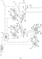
Fig. 1 is a diagram schematically illustrating an electrohydraulic robot according to an embodiment of the present invention. -
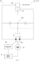
Fig. 2 is a circuit diagram illustrating a hydraulic circuit included in the electrohydraulic robot illustrated inFig. 1 . -
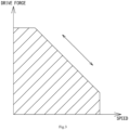
Fig. 3 is a diagram illustrating the speed-torque relationship of a hydraulic cylinder included in the electrohydraulic robot illustrated inFig. 1 . -
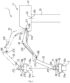
Fig. 4 is a diagram illustrating how the electrohydraulic robot illustrated inFig. 1 is actuated on the basis of a movement plan. - Hereinafter, an electrohydraulic robot 1 (hereinafter referred to simply as "the robot") according to an embodiment of the present invention will be described with reference to the aforementioned drawings. Note that the concept of directions mentioned in the following description is used for the sake of explanation; the orientations, etc., of elements according to the invention are not limited to these directions. Furthermore, the
robot 1 described below is merely one embodiment of the present invention. Thus, the present invention is not limited to the embodiments and may be subject to addition, deletion, and alteration within the scope of the essence of the invention. - The
robot 1 illustrated inFig. 1 can be driven using electric power and a working fluid (oils, water, or other fluids). Therobot 1 is placed at a work site such as a production line in a factory, for example. Therobot 1 is capable of performing various tasks such as transporting, assembling, and painting. Therobot 1 is an articulated robot. Therobot 1 is an industrial robot, construction equipment such as an excavator and a crane, a tunnel boring machine, a cargo vehicle, a service robot, or a humanoid, for example. In the present embodiment, therobot 1 is a vertical articulated industrial robot. Therobot 1 includes amanipulator 11, a plurality ofdrive devices 12 to 15, a plurality ofangular displacement sensors 16A to 16D, anoperation device 17, and acontrol device 18. - The
manipulator 11 includes a plurality of joints JT0 to JT4. In the present embodiment, themanipulator 11 includes five joints JT0 to JT4. Note that the number of joints JT0 to JT4 of themanipulator 11 is not limited to four and may be three or four or may be six or more. Furthermore, the shape of themanipulator 11 is not limited to that described below. More specifically, themanipulator 11 includes a turningbody 21, afirst arm 22, asecond arm 23, athird arm 24, and anend effector 25. Theelements 21 to 25 are coupled to each other in such a manner as to allow angular displacement thereof. Portions ofmanipulator 11 at which theelements 21 to 25 are coupled to each other constitute the joints JT0 to JT4. Themanipulator 11 can assume various postures by moving the plurality of joints JT0 to JT4. Furthermore, themanipulator 11 can perform various tasks by operating theend effector 25. Hereinafter, theelements 21 to 25 will be described in detail. - The turning
body 21 is fixed to a floor or the like via abase 20. The turningbody 21 is provided on thebase 20 in such a manner as to be able to rotate about a predetermined axial line L0. The turningbody 21 constitutes the joint JT0 at a portion coupled to the base 30. Note that the shape of thebase 20 is not limited to the aforementioned shape. The turningbody 21 may be provided on a traveling device that travels on the floor, the ground, or the like. The turningbody 21 is turned using a driver not illustrated in the drawings, for example, an electric motor or a hydraulic motor. Thus, the orientation of the turning body 21 (more specifically, the orientation of the manipulator 11) can be changed. - The
first arm 22 is rotatably coupled to the turningbody 21. More specifically, one end portion of thefirst arm 22 is rotatably coupled to a front portion of the turningbody 21. Thefirst arm 22 constitutes the first joint JT1 at a portion coupled to the turningbody 21. More specifically, thefirst arm 22 extends diagonally upward to the front from the turningbody 21, for example. At the first joint JT1, thefirst arm 22 can swing vertically with respect to the turningbody 21. - The
second arm 23 is rotatably coupled to thefirst arm 22. More specifically, one end portion of thesecond arm 23 is rotatably coupled to the other end portion of thefirst arm 22. Thesecond arm 23 constitutes the second joint JT2 at a portion coupled to thefirst arm 22. More specifically, thesecond arm 23 extends diagonally downward to the front from the other end of thefirst arm 22, for example. At the second joint JT2, thesecond arm 23 can swing depthwise with respect to thefirst arm 22. - The
third arm 24 is rotatably coupled to thesecond arm 23. More specifically, one end portion of thethird arm 24 is rotatably coupled to the other end portion of thesecond arm 23. Thethird arm 24 constitutes the third joint JT3 at a portion coupled to thesecond arm 23. More specifically, thethird arm 24 extends downward from the other end of thesecond arm 23, for example. At the third joint JT3, thethird arm 24 can swing depthwise with respect to thesecond arm 23. - The
end effector 25 is rotatably coupled to thethird arm 24. More specifically, theend effector 25 is coupled to the other end of thethird arm 24 in such a manner as to be able to rotate about an axial line orthogonal to the other end surface of thethird arm 24. Theend effector 25 constitutes the fourth joint JT4 at a portion coupled to thethird arm 24. At the fourth joint JT4, theend effector 25 can rotate about said axial line with respect to thethird arm 24. Theend effector 25 disposed as just described is a device that performs various tasks on a workpiece 2 (refer to theworkpiece 2 illustrated inFig. 4 which will be described later). More specifically, theend effector 25 is a hand that picks theworkpiece 2, a suction device that attaches to theworkpiece 2 by suction and lifts theworkpiece 2, a screwdriver that tightens a screw on theworkpiece 2, or a welding machine that welds theworkpiece 2, for example. In the present embodiment, theend effector 25 is a hand and picks theworkpiece 2 by closing a pair ofgrippers 25a. - The plurality of
drive devices 12 to 15 are independently provided in a one-to-one correspondence with the four joints JT1 to JT4. The first tofourth drive devices 12 to 15 move the corresponding joints JT1 to JT4. Hereinafter, the elements of the first tofourth drive devices 12 to 15 will be described in detail. On the other hand, the first tothird drive devices 12 to 14 have similar elements. Therefore, regarding the first tothird drive devices 12 to 14, elements of thefirst drive device 12 will be mainly described. Elements of the second andthird drive devices first drive device 12 will be assigned the same reference signs and description thereof will be omitted while elements of the second andthird drive devices first drive device 12 will be mainly described. - The
first drive device 12 moves the first joint JT1. Specifically, thefirst drive device 12 drives thefirst arm 22 so that thefirst arm 22 swings with respect to the turningbody 21. More specifically, thefirst drive device 12 includes a firsthydraulic cylinder 31A, ahydraulic pump 32, anelectric motor 33, and ahydraulic circuit 34, as illustrated inFig. 2 . Thefirst drive device 12 is a hydraulically driven actuator. Specifically, thefirst drive device 12 drives thehydraulic pump 32 using theelectric motor 33. Furthermore, thefirst drive device 12 actuates the firsthydraulic cylinder 31A using a pressurized fluid discharged from thehydraulic pump 32. Hereinafter, the elements of thefirst drive device 12 will be described in detail. - The first
hydraulic cylinder 31A, which is one example of the hydraulic actuator, moves the corresponding joint JT1, namely, the first joint JT1. More specifically, the firsthydraulic cylinder 31A is provided so as to serve as a bridge between the turningbody 21 and thefirst arm 22, as illustrated inFig. 1 . Furthermore, the firsthydraulic cylinder 31A can stretch when supplied with the pressurized fluid. By stretching, the firsthydraulic cylinder 31A causes thefirst arm 22 to swing with respect to the turningbody 21, in other words, moves the firstjoint JT 1. - The
hydraulic pump 32 illustrated inFig. 2 discharges the pressurized fluid in order to supply the working fluid to the firsthydraulic actuator 31A. More specifically, thehydraulic pump 32 discharges the pressurized fluid in one direction and the other direction according to a rotational direction. Thehydraulic pump 32 is a pump of the variable capacity type with a discharge capacity varying according to a command from thecontrol device 18, which will be described later. In the present embodiment, thehydraulic pump 32 is a swash plate pump of the variable capacity type. Specifically, thehydraulic pump 32 includes aregulator 32a and aswash plate 32b. Theregulator 32a is driven using a direct-acting motor or a pilot pressure output from a control valve not illustrated in the drawings. When driven, theregulator 32a changes the tilt angle of theswash plate 32b. Accordingly, the discharge capacity of thehydraulic pump 32 is changed. Note that thehydraulic pump 32 is not limited to the swash plate pump of the variable capacity type and may be an axial piston pump of the variable capacity type or may be any pump with a variable discharge capacity. Thehydraulic pump 32 is attached to a portion other than a corresponding arm, that is, thefirst arm 22. Thehydraulic pump 32 is attached to a floor (not illustrated in the drawings) to which the turningbody 21 and the base 20 are fixed, for example. Note that the attachment position is not limited to said position. - The
electric motor 33 drives thehydraulic pump 32. More specifically, theelectric motor 33 rotatably drives thehydraulic pump 32 to cause thehydraulic pump 32 to discharge the pressurized fluid. Theelectric motor 33 can rotatably drives thehydraulic pump 32 forward and backward. Thus, theelectric motor 33 can cause thehydraulic pump 32 to discharge the pressurized fluid in one direction and the other direction. In the present embodiment, theelectric motor 33 is a servomotor. Note that theelectric motor 33 is not limited to the servomotor and may be another motor. Theelectric motor 33 is attached to a floor (not illustrated in the drawings) to which the turningbody 21 and the base 20 are fixed, for example. Note that the attachment position is not limited to said position. - The
hydraulic circuit 34 connects the firsthydraulic cylinder 31A and thehydraulic pump 32. More specifically, thehydraulic circuit 34 supplies the firsthydraulic cylinder 31A with the pressurized fluid discharged from thehydraulic pump 32 and causes the pressurized fluid to be drained from the firsthydraulic cylinder 31A. In the present embodiment, thehydraulic circuit 34 forms a closed circuit together with the firsthydraulic cylinder 31A and thehydraulic pump 32. Specifically, thehydraulic circuit 34 supplies the firsthydraulic cylinder 31A with the pressurized fluid discharged from thehydraulic pump 32 and returns the pressurized fluid from the firsthydraulic cylinder 31A to thehydraulic pump 32. For example, thehydraulic circuit 34 brings, to a rod-end port 31a of the firsthydraulic cylinder 31A, the pressurized fluid discharged from thehydraulic pump 32 in one direction, and also brings, to a head-end portion 31b of the firsthydraulic cylinder 31A, the pressurized fluid discharged from thehydraulic pump 32 in the other direction. Thus, the firsthydraulic cylinder 31A stretches. Furthermore, thehydraulic circuit 34 includes a supply/drain mechanism 34a. The supply/drain mechanism 34a brings, back to a tank, a portion of the pressurized fluid drained from the head-end port 31b of the firsthydraulic cylinder 31A. Furthermore, the supply/drain mechanism 34a adds a fluid pressure to compensate for an insufficient fluid pressure when supplying the pressurized fluid to the rod-end port 31a of the firsthydraulic cylinder 31A. Note that the configuration of the supply/drain mechanism 34a is not limited to that illustrated inFig. 2 . - In the
first drive device 12 configured as described above, theelectric motor 33 drives thehydraulic pump 32. Thus, the pressurized fluid is discharged from thehydraulic pump 32 in one of the first direction and the other direction according to the rotational direction. For example, when the pressurized fluid is discharged from thehydraulic pump 32 in one direction, the firsthydraulic cylinder 31A is retracted. This causes thefirst arm 22 to swing downward at the first joint JT1. On the other hand, when the pressurized fluid is discharged from thehydraulic pump 32 in the other direction, the firsthydraulic cylinder 31A is extended. This causes thefirst arm 22 to swing upward at the first joint JT1. - The
second drive device 13 moves the second joint JT2. Specifically, thesecond drive device 13 causes thesecond arm 23 to swing with respect to thefirst arm 22. More specifically, thesecond drive device 13 includes a secondhydraulic cylinder 31B, ahydraulic pump 32, anelectric motor 33, and ahydraulic circuit 34. - The second
hydraulic cylinder 31B, which is one example of the hydraulic actuator, moves the corresponding joint JT2, namely, the second joint JT2. More specifically, the secondhydraulic cylinder 31B is provided so as to serve as a bridge between thefirst arm 22 and thesecond arm 23, as illustrated inFig. 1 . Furthermore, the secondhydraulic cylinder 31B can stretch when supplied with the pressurized fluid. By stretching, the secondhydraulic cylinder 31B causes thesecond arm 23 to swing with respect to thefirst arm 22, in other words, moves the second joint JT2. - In the
second drive device 13 configured as described above, when theelectric motor 33 drives thehydraulic pump 32 so that the pressurized fluid is discharged from thehydraulic pump 32 in one direction, the secondhydraulic cylinder 31B is retracted. This causes thesecond arm 23 to swing forward at the second joint JT2. On the other hand, when the pressurized fluid is discharged from thehydraulic pump 32 in the other direction, the secondhydraulic cylinder 31B is extended. This causes thesecond arm 23 to swing backward at the second joint JT2. - The
third drive device 14 moves the third joint JT3. Specifically, thethird drive device 14 causes thethird arm 24 to swing with respect to thesecond arm 23. More specifically, thethird drive device 14 includes a thirdhydraulic cylinder 31C, ahydraulic pump 32, anelectric motor 33, and ahydraulic circuit 34. - The third
hydraulic cylinder 31C, which is one example of the hydraulic actuator, moves the corresponding joint JT3, namely, the third joint JT3. More specifically, the thirdhydraulic cylinder 31C is provided so as to serve as a bridge between thesecond arm 23 and thethird arm 24, as illustrated inFig. 1 . Furthermore, the thirdhydraulic cylinder 31C can stretch when supplied with the pressurized fluid. By stretching, the thirdhydraulic cylinder 31C causes thethird arm 24 to swing with respect to thesecond arm 23, in other words, moves the third joint JT3. - In the
third drive device 14 configured as described above, when theelectric motor 33 drives thehydraulic pump 32 so that the pressurized fluid is discharged from thehydraulic pump 32 in one direction, the thirdhydraulic cylinder 31C is retracted. This causes thethird arm 24 to swing backward at the third j oint JT3. On the other hand, when the pressurized fluid is discharged from thehydraulic pump 32 in the other direction, the thirdhydraulic cylinder 31C is extended. This causes thethird arm 24 to swing forward at the third joint JT3. - The
fourth drive device 15 moves the fourth joint JT4. Thefourth drive device 15 rotates theend effector 25 with respect to thethird arm 24. More specifically, thefourth drive device 15 includes an electric motor and a speed reducer not illustrated in the drawings. When the electric motor is driven, theend effector 25 is rotatably driven via the speed reducer. - The
angular displacement sensors 16A to 16D, which are one example of the displacement amount detector and the position detector, detect the amounts of displacement of the joints JT1 to JT4 of themanipulator 11. More specifically, theangular displacement sensors 16A to 16D are provided in a one-to-one correspondence with the joints JT1 to JT4. Theangular displacement sensors 16A to 16D detect the amounts of angular displacement (i.e., the tilt angles) of the joints JT1 to JT4 of themanipulator 11. - The
operation device 17 illustrated inFig. 1 provides a position command about the position of theend effector 25. Theoperation device 17 is, for example, a joystick, and includes an operation lever not illustrated in the drawings, for example. Theoperation device 17 outputs a position command corresponding to the direction and angle of tilt (i.e., the amount of operation) of the operation lever. Note that theoperation device 17 does not need to be a joystick and may be a touch panel on which an operation can be performed via a screen. Furthermore, theoperation device 17 does not necessarily need to output the position command and may receive the movement plan, which will be described later. - The
control device 18 controls the movement of the driver that drives the turningbody 21 and each of the first tofourth drive devices 12 to 15. Furthermore, thecontrol device 18 moves each of the joints JT0 to JT4 of themanipulator 11. More specifically, using the driver, thecontrol device 18 causes the turningbody 21 to turn, in other words, moves the joint JT0. Thus, thecontrol device 18 changes the orientation of themanipulator 11. Furthermore, thecontrol device 18 drives theelectric motors 33 of the first tothird drive devices 12 to 14, causing the working fluid to be discharged from the hydraulic pumps 32. Thus, thehydraulic cylinders third arms 22 to 24 swing, meaning that the first to third joints JT1 to JT3 move. Furthermore, thecontrol device 18 controls the position of theend effector 25 by moving each of thejoints JT 1 to JT3. In addition, by controlling the movement of the joint JT4 and the movement of theend effector 25, thecontrol device 18 causes theworkpiece 2 to be picked and held. Moreover, thecontrol device 18 adjusts the discharge capacity of thehydraulic pump 32. Specifically, thecontrol device 18 adjusts the discharge capacity of thehydraulic pump 32 by controlling the operation of the control valve or the direct-acting motor (not illustrated in the drawings) of theregulator 32a. Furthermore, thecontrol device 18 controls the discharge pressure and the discharge flow rate at thehydraulic pump 32. Thus, thecontrol device 18 can adjust the drive force (in the present embodiment, the thrust) and the speed of thehydraulic cylinders 31A to 31C (refer toFig. 3 ). - More specifically, in the
control device 18, the movement plan regarding themanipulator 11 is stored. Thecontrol device 18 controls the movement of the driver in accordance with the movement plan or the operation command from theoperation device 17. Thus, thecontrol device 18 changes the orientation of theend effector 25. Furthermore, thecontrol device 18 controls the operation of theelectric motors 33 and the discharge capacity of thehydraulic pumps 32 of the first to thethird drive devices 12 to 14 in accordance with the movement plan or the operation command from theoperation device 17. Thus, thecontrol device 18 changes the position of theend effector 25. Here, the movement plan is a plan regarding a path in which theend effector 25 moves and tasks for the end effector 25 (in the present embodiment, the task of picking and holding theworkpiece 2 and the task of releasing theworkpiece 2, for example). The movement plan is stored into thecontrol device 18 in advance as a program or is selectively input from theoperation device 17. - More specifically, the
control device 18 obtains detection results from theangular displacement sensors 16A to 16C. Subsequently, thecontrol device 18 controls the discharge capacity of thehydraulic pumps 32 of thedrive devices 12 to 14 on the basis of the movement plan and the detection results from theangular displacement sensors 16A to 16C. More specifically, thecontrol device 18 calculates a target amount of displacement (that is a target amount of angular displacement and will be hereinafter referred to as "the target value" in the present embodiment) of each of the joints JT1 to JT3 on the basis of the movement plan (for example, the trajectory of the end effector 25), for example. Note that the target value may be included in the movement plan. Subsequently, thecontrol device 18 compares the target value and the amounts of displacement of the joints JT1 to JT3 detected by theangular displacement sensors 16A to 16C (each of which is the amount of angular displacement detected and will be hereinafter referred to as "the actual value" in the present embodiment). Furthermore, thecontrol device 18 drives theelectric motor 33 of each of thedrive devices 12 to 14 so that the target value and the actual value match. Thus, thecontrol device 18 changes the position of theend effector 25. - Furthermore, the
control device 18 controls the discharge capacity of thehydraulic pump 32 of each of thedrive devices 12 to 14 according to the difference between the target value and the actual value included in the comparison result. For example, when the actual value is less than the target value, the discharge capacity of thehydraulic pump 32 is increased. On the other hand, when the actual value exceeds the target value, the discharge capacity of thehydraulic pump 32 is reduced. Thus, the drive force to be generated at thehydraulic cylinders 31A to 31C is adjusted; note that in the present embodiment, thecontrol device 18 adjusts the drive force at thehydraulic cylinders 31A to 31C by controlling the output torque of theelectric motor 33. When the output torque of theelectric motor 33 reaches a predetermined torque (for example, the maximum torque), thecontrol device 18 adjusts the discharge capacity of thehydraulic pump 32 to adjust the drive force at thehydraulic cylinders 31A to 31C. However, thecontrol device 18 does not necessarily need to adjust the discharge capacity of thehydraulic pump 32 when the output torque of theelectric motor 33 reaches the predetermined torque (for example, the maximum torque). For example, thecontrol device 18 may comprehensively control the output torque of theelectric motor 33 and the discharge capacity of thehydraulic pump 32 according to the energy efficiency or the like. - The following will describe the case where the
control device 18 automatically operates themanipulator 11 on the basis of the movement plan and theangular displacement sensors 16A to 16C in therobot 1. For example, in the state where theend effector 25 is not holding theworkpiece 2, thecontrol device 18 moves themanipulator 11 as follows. Specifically, thecontrol device 18 changes the position of theend effector 25 on the basis of the movement plan. More specifically, thecontrol device 18 changes the position of theend effector 25 by driving theelectric motor 33 of each of thedrive devices 12 to 14. For example, in a standby state before the movement plan is started, thecontrol device 18 maximizes the discharge capacity of thehydraulic pump 32. Thecontrol device 18 drives theelectric motor 33 of each of thedrive devices 12 to 14 while the discharge capacity of the hydraulic pump32 is maximum (this state will be hereinafter referred to as "the maximized state"). Furthermore, thecontrol device 18 controls the position of theend effector 25 by driving theelectric motor 33 of each of thedrive devices 12 to 14 on the basis of the result of comparison between the target value and the actual value (the comparison result). - Next, the case will be described in which the
control device 18 automatically operates themanipulator 11 on the basis of the movement plan indicating that theend effector 25 is to vertically lift theworkpiece 2, as illustrated inFig. 4 , after theend effector 25 moves down and picks and holds theworkpiece 2. This means that thecontrol device 18 controls the position of theend effector 25 in the aforementioned method in the state where theend effector 25 is not picking or holding theworkpiece 2. After moving theend effector 25 down to theworkpiece 2, thecontrol device 18 actuates the fourth joint JT4 and theend effector 25, thereby causing theend effector 25 to pick and hold theworkpiece 2. - After the
workpiece 2 is successfully picked and held, thecontrol device 18 moves up theend effector 25 holding theworkpiece 2 on the basis of the movement plan. More specifically, thecontrol device 18 moves up theend effector 25 by driving theelectric motor 33 of each of thedrive devices 12 to 14. At this time, thecontrol device 18 also controls the discharge capacity of thehydraulic pump 32 of each of thedrive devices 12 to 14 according to the loads on the first to third joints JT1 to JT3. Specifically, thecontrol device 18 compares the target value and the actual value of each of the first to third joints JT1 to JT3. Subsequently, thecontrol device 18 first adjusts the output torque of theelectric motor 33 of each of thedrive devices 12 to 14 according to the difference between the target value and the actual value. For example, when theworkpiece 2 has a low weight, thecontrol device 18 can adjust the output torque of theelectric motor 33 while maintaining the maximized state. This allows thecontrol device 18 to secure the discharge flow rate at thehydraulic pump 32 while reducing the discharge pressure at thehydraulic pump 32. Therefore, thecontrol device 18 can move themanipulator 11 in a speed-focused manner. - On the other hand, when the
workpiece 2 has a high weight, thecontrol device 18 controls each of thedrive devices 12 to 15 as follows. Specifically, when the output torque of theelectric motor 33 reaches the maximum and the actual value is less than the target value, thecontrol device 18 reduces the discharge capacity of thehydraulic pump 32 of each of thedrive devices 12 to 14. Thus, thecontrol device 18 can increase the discharge pressure at thehydraulic pump 32 of each of thedrive devices 12 to 15. In other words, thecontrol device 18 can generate a greater drive force at the hydraulic actuator. Therefore, thecontrol device 18 can cause themanipulator 11 to lift a high-load workpiece 2. In other words, thecontrol device 18 can move themanipulator 11 in a drive-force-focused manner. Note that when the target value exceeds the actual value, thecontrol device 18 increases the discharge capacity of thehydraulic pump 32 of each of thedrive devices 12 to 14 or controls the output torque of theelectric motor 33 of each of thedrive devices 12 to 14. Accordingly, the drive force at each of thehydraulic cylinders 31A to 31C is reduced, and thus the actual value can approach the target value. - In the
robot 1 according to the present embodiment, when automatically operating themanipulator 11 on the basis of the movement plan, thecontrol device 18 controls the discharge pressure and the discharge flow rate by adjusting the discharge capacity of thehydraulic pump 32 of each of thedrive devices 12 to 14. This allows thecontrol device 18 to adjust the drive force and the speed of each of thehydraulic cylinders 31A to 31C. This means that thecontrol device 18 can move each of the j oints JT1 to JT3 in a drive-force-focused manner and a speed-focused manner by adjusting the discharge capacity of thehydraulic pump 32. Therefore, it is possible to make a desired movement at each of the joints JT1 to JT3 when moving the plurality of joints JT1 to JT3. In other words, one of a high-speed, low torque and a low-speed, high torque is selected as the drive state of each of the joints JT1 o JT3. Therefore, the maximum torque required for theelectric motor 33 can be reduced. Accordingly, the size of theelectric motor 33 can be reduced. - Furthermore, in the
robot 1, by adjusting the discharge capacity of thehydraulic pump 32 when controlling the position of theend effector 25, it is possible to reduce the occurrence of the drive force at each of the joints JT1 to JT3 becoming insufficient. Thus, the joints JT1 to JT3 can be moved in conjunction according to the movement plan and therefore, theend effector 25 can be moved along a desired path (that is, a path indicated in the movement plan). This allows for improved work efficiency of themanipulator 11. - Furthermore, in the
robot 1, thecontrol device 18 controls the discharge capacity of thehydraulic pump 32 and theelectric motor 33 of each of thedrive devices 12 to 14 in accordance with the movement plan stored in advance. Therefore, thecontrol device 18 can more appropriately move the joints JT1 to JT3. This allows for improved work efficiency of themanipulator 11. - Furthermore, in the
robot 1, thecontrol device 18 controls the discharge capacity of the hydraulic pump32 on the basis of the target value and the actual value regarding the position of each of the joints JT1 to JT3. For example, when the actual value is less than the target value because the drive force at each of the joints JT1 to JT3 is insufficient, the drive force can be increased by reducing the discharge capacity of thehydraulic pump 32. Therefore, it is possible to minimize the reduction in the work efficiency of themanipulator 11 that occurs due to an insufficient torque of theelectric motor 33. - Furthermore, in the
robot 1, since thehydraulic circuit 34 forms a closed circuit, a pressure loss can be reduced, and the number of components can be reduced. - The following will describe the case where the
control device 18 automatically operates themanipulator 11 on the basis of a load that is set in the movement plan (hereinafter referred to as "the set load") in therobot 1. Specifically, thecontrol device 18 changes the position of theend effector 25 on the basis of the set load. In other words, thecontrol device 18 drives theelectric motor 33 while controlling the discharge capacity of thehydraulic pump 32 according to the set load in each of thedrive devices 12 to 14. More specifically, when the set load is less than or equal to a predetermined drive force, the output torque of theelectric motor 33 is controlled while the maximized state is maintained. Here, the predetermined drive force refers to the drive force generated at thehydraulic cylinders 31A to 31C when the output torque of theelectric motor 33 reaches the maximum torque while the maximized state is maintained, for example. On the other hand, when the set load exceeds the predetermined drive force, thecontrol device 18 sets the output torque of theelectric motor 33 to the maximum torque and controls the discharge capacity of thehydraulic pump 32 according to the set load. Thus, thecontrol device 18 can cause a desired drive force to be generated at each of thehydraulic cylinders 31A to 31C. In other words, thecontrol device 18 can cause a torque corresponding to the set load to be generated at each of the joints JT1 to JT3. Thus, thecontrol device 18 can move themanipulator 11 in accordance with the movement plan. - In the
robot 1 according to the present embodiment, when thecontrol device 18 operates themanipulator 11 on the basis of the set load, it is possible to minimize the reduction in the work efficiency of themanipulator 11 that occurs due to an insufficient torque and a speed reduction of theelectric motor 33. - Furthermore, in the
robot 1, in the case where themanipulator 11 is automatically operated on the basis of the set load, thecontrol device 18 can determine, before actual movement, a drive force required by each of the joints JT1 to JT3 at a corresponding position during the movement based on the movement plan. Therefore, the movement plan may include how to change the discharge capacity of thehydraulic pump 32 during the control of the drive force. - Aside from this, when automatically operating the
manipulator 11 on the basis of the set load, therobot 1 produces advantageous effects that are substantially the same as those produced when automatically operating themanipulator 11 on the basis of the movement plan. - The following will describe the case where the
control device 18 moves themanipulator 11 on the basis of an operation performed on the operation lever of theoperation device 17 in therobot 1. For example, in the state where theend effector 25 is not picking or holding theworkpiece 2, thecontrol device 18 moves themanipulator 11 as follows. Specifically, when the operation lever is operated, thecontrol device 18 changes the position of theend effector 25 on the basis of the position command from theoperation device 17. More specifically, thecontrol device 18 drives theelectric motor 33 of each of thedrive devices 12 to 14 while the maximized state is maintained. Furthermore, thecontrol device 18 calculates a target value for each of the joints JT1 to JT3 on the basis of the position command. Subsequently, as in the case of automatic operation, thecontrol device 18 controls the position of theend effector 25 by driving theelectric motor 33 of each of thedrive devices 12 to 14 on the basis of the result of comparison between the position command (more specifically, the target value) and the actual value. Note that the command from thecontrol device 18 is not limited to the position command and may be a speed command (a rotational speed command). In this case, thecontrol device 18 drives theelectric motor 33 of each of thedrive devices 12 to 14 on the basis of the result of comparison between the speed command and an actual value (that is, an actual speed). Thus, the speed of theend effector 25 is controlled. - Next, the case will be described where the
end effector 25 is moved up in the state where theworkpiece 2 is held as illustrated inFig. 4 . When the operation lever is operated in the state where theend effector 25 is holding theworkpiece 2, thecontrol device 18 controls the movement of each of thedrive devices 12 to 14 as follows, specifically, thecontrol device 18 compares the target value and the actual value as in the case of automatic operation. Subsequently, thecontrol device 18 first adjusts the output torque of theelectric motor 33 of each of thedrive devices 12 to 14 according to the difference between the target value and the actual value. As with the movement plan, when theworkpiece 2 has a low weight, thecontrol device 18 adjusts the output torque of theelectric motor 33 while maintaining the maximized state. On the other hand, when the output torque of theelectric motor 33 reaches the maximum and the actual value is less than the target value, thecontrol device 18 reduces the discharge capacity of thehydraulic pump 32 of each of thedrive devices 12 to 14. Thus, thecontrol device 18 can move themanipulator 11 in a drive-force-focused manner. When the actual value exceeds the target value, thecontrol device 18 reduces the discharge capacity of thehydraulic pump 32 of each of thedrive devices 12 to 14 or controls the output torque of theelectric motor 33 of each of thedrive devices 12 to 14. Accordingly, the drive force at each of thehydraulic cylinders 31A to 31C is reduced, and thus the actual value can approach the target value. - In the
robot 1 according to the present embodiment, when moving themanipulator 11 on the basis of the position command from theoperation device 17, thecontrol device 18 controls the discharge capacity of thehydraulic pump 32 on the basis of the actual value and the target value based on the position in the command. For example, when the actual value is less than the target value because the drive force at each of the joints is insufficient, the drive force can be increased by reducing the discharge capacity of thehydraulic pump 32. Therefore, it is possible to minimize the reduction in the work efficiency of themanipulator 11 that occurs due to an insufficient torque of theelectric motor 33. - Aside from this, when moving the
manipulator 11 on the basis of the position command from theoperation device 17, therobot 1 produces advantageous effects that are substantially the same as those produced when automatically operating themanipulator 11 on the basis of the movement plan. - The form of the
manipulator 11 in therobot 1 according to the present embodiment is merely one example. Specifically, therobot 1 is a vertical articulated robot in the present embodiment, but may be a different articulated robot such as a horizontal articulated robot. Furthermore, therobot 1 may be a serial-link robot or a parallel-link robot such as another coordinate-axis robot. The end effector does not need to be formed at the tip portion of themanipulator 11 and may be formed midway through themanipulator 11. Furthermore, theend effector 25 is not limited to the hand and may be a bucket, a breaker, or the like of construction equipment or may be a different end effector and an attachment. Moreover, theoperation device 17 is not limited either to that including the operation lever and may be a touch panel, a switch, or the like. In other words, it is sufficient that theoperation device 17 be an element to which the command can be input. - Furthermore, in the
robot 1, the hydraulic actuator is each of thehydraulic cylinders 31A to 31C, but may be a hydraulic motor. For example, thedrive device 15 that moves the fourth joint JT4 and a turning device that turns the turningbody 21 are configured to include a hydraulic motor which is one example of the hydraulic actuator. Thecontrol device 18 controls the movement of the electric motor on the basis of the movement plan and theoperation device 17, thereby causing the pressurized fluid to be supplied from thehydraulic pump 32 to the hydraulic motor. Furthermore, thecontrol device 18 controls the torque of the hydraulic motor by adjusting the discharge capacity of thehydraulic pump 32. Thus, a torque greater than or equal to the maximum torque of the electric motor can be generated at the fourth joint JT4 and the turningbody 21. - Furthermore, in the
robot 1, the hydraulic actuators that drive the first to third joints JT1 to JT3 are not limited either to thehydraulic cylinders 31A to 31C. The hydraulic actuators may be hydraulic motors. Furthermore, the first to third joints JT1 to JT3 are not limited either to revolute joints and may be prismatic joints. Note that in the case of prismatic joints, the position detector detects an amount of expansion and contraction of the arm, and thecontrol device 18 controls the drive devices so that the amount of expansion and contraction reaches the target value. - Furthermore, in the
robot 1, thehydraulic pump 32 is a single-tilting swash plate pump, but thehydraulic pump 32 may be a double-tilting swash plate pump. Moreover, in therobot 1, thehydraulic circuit 34 forms a closed circuit, but may form an open circuit. The method for controlling each of thedrive devices 12 to 14 by thecontrol device 18 in therobot 1 is not limited either to the aforementioned method. Therobot 1 includes theoperation device 17, but does not necessarily need to include theoperation device 17. - Furthermore, in the
robot 1, the discharge capacity of thehydraulic pump 32 is maximized, and the torque of theelectric motor 33 is adjusted to adjust the drive force (the speed-focused manner). Subsequently, when the torque of theelectric motor 33 exceeds the maximum, the discharge capacity of thehydraulic pump 32 is changed (the drive-force-focused manner). However, the method for controlling the discharge capacity of thehydraulic pump 32 and the torque of theelectric motor 33 is not limited to this method. For example, thecontrol device 18 minimizes the discharge capacity of thehydraulic pump 32 and adjusts the torque of theelectric motor 33 to adjust the drive force (the drive-force-focused manner). Subsequently, when the torque of theelectric motor 33 exceeds the maximum, thecontrol device 18 changes the discharge capacity of the hydraulic pump 32 (the speed-focused manner). - Furthermore, the
control device 18 may change the discharge capacity of thehydraulic pump 32 before the torque of theelectric motor 33 reaches the maximum. Specifically, thecontrol device 18 may control the torque (or the rotational speed) of theelectric motor 33 and the discharge capacity of thehydraulic pump 32 so that the total efficiency of theelectric motor 33 and thehydraulic pump 32 is maximized (an efficiency-focused manner), for example. Aside from this, another control method may also be used to control the operation of theelectric motor 33 and the discharge capacity of thehydraulic pump 32. - From the foregoing description, many modifications and other embodiments of the present invention would be obvious to a person having ordinary skill in the art. Therefore, the foregoing description should be interpreted only as an example and is provided for the purpose of teaching the best mode for carrying out the present invention to a person having ordinary skill in the art. Substantial changes in details of the structures and/or functions of the present invention are possible within the spirit of the present invention.
Claims (8)
- An electrohydraulic robot comprising:a manipulator including a plurality of joints;a plurality of drive devices that are provided in a one-to-one correspondence with the plurality of joints and each move a corresponding one of the plurality of joints; anda control device that controls movement of each of the plurality of drive devices, wherein:each of the plurality of drive devices includes: a hydraulic actuator that moves a corresponding one of the plurality of joints; a hydraulic pump of a variable capacity type that supplies a working fluid to the hydraulic actuator; and an electric motor that drives the hydraulic pump; andthe control device controls an operation of the electric motor and a discharge capacity of the hydraulic pump in each of the plurality of drive devices.
- The electrohydraulic robot according to claim 1, wherein:the manipulator includes an end effector; andthe control device moves the manipulator and controls a position of the end effector by controlling the operation of the electric motor and the discharge capacity of the hydraulic pump in each of the plurality of drive devices.
- The electrohydraulic robot according to claim 1 or 2, wherein:each of the plurality of drive devices further includes a hydraulic circuit that connects the hydraulic actuator and the hydraulic pump; andthe hydraulic circuit forms a closed circuit together with the hydraulic actuator and the hydraulic pump.
- The electrohydraulic robot according to any one of claims 1 to 3, wherein:
the control device stores a movement plan regarding the manipulator and controls the operation of the electric motor and the discharge capacity of the hydraulic pump in each of the plurality of drive devices in accordance with the movement plan. - The electrohydraulic robot according to claim 4, further comprising:a displacement amount detector that detects an amount of displacement of each of the plurality of joints of the manipulator, wherein:the movement plan includes a target value of a position of each of the plurality of joints; andthe control device controls the discharge capacity of the hydraulic pump in each of the plurality of drive devices on the basis of the target value included in the movement plan and a result of the detection by the displacement amount detector.
- The electrohydraulic robot according to claim 4, wherein:
when a load on each of the plurality of joints that is set in the movement plan is greater than or equal to a predetermined drive force, the control device controls the discharge capacity of the hydraulic pump in a corresponding one of the plurality of drive devices. - The electrohydraulic robot according to claim 2, further comprising:an operation device that outputs a position command about the position of the end effector; anda position detector that detects a position of each of the plurality of joints of the manipulator, wherein:
the control device controls the discharge capacity of the hydraulic pump in each of the plurality of drive devices on the basis of the position command from the operation device and a result of the detection by the position detector. - The electrohydraulic robot according to any one of claims 1 to 6, wherein:the hydraulic actuator is a hydraulic cylinder that is extended and retracted according to supply of the working fluid from the hydraulic pump; andthe hydraulic cylinder is extended and retracted to move a corresponding one of the plurality of joints of the manipulator.
Applications Claiming Priority (2)
| Application Number | Priority Date | Filing Date | Title |
|---|---|---|---|
| JP2021105637A JP2023004126A (en) | 2021-06-25 | 2021-06-25 | Electric fluid pressure type robot |
| PCT/JP2022/020228 WO2022270177A1 (en) | 2021-06-25 | 2022-05-13 | Electrohydraulic robot |
Publications (2)
| Publication Number | Publication Date |
|---|---|
| EP4360815A1 true EP4360815A1 (en) | 2024-05-01 |
| EP4360815A4 EP4360815A4 (en) | 2025-06-18 |
Family
ID=84544502
Family Applications (1)
| Application Number | Title | Priority Date | Filing Date |
|---|---|---|---|
| EP22828096.2A Pending EP4360815A4 (en) | 2021-06-25 | 2022-05-13 | ELECTROHYDRAULIC ROBOT |
Country Status (6)
| Country | Link |
|---|---|
| US (1) | US20240238965A1 (en) |
| EP (1) | EP4360815A4 (en) |
| JP (1) | JP2023004126A (en) |
| KR (1) | KR20230129503A (en) |
| CN (1) | CN117279747A (en) |
| WO (1) | WO2022270177A1 (en) |
Family Cites Families (24)
| Publication number | Priority date | Publication date | Assignee | Title |
|---|---|---|---|---|
| US4086710A (en) * | 1973-10-25 | 1978-05-02 | Craine James F | Brain damage testing |
| DK146819C (en) * | 1981-03-03 | 1984-06-25 | Bates Ventilsaekke | APPARATUS FOR SEALING THE VALVE IN A VALVE BAG WITH AN ADMINISTRATIVE |
| US4442387A (en) * | 1981-11-25 | 1984-04-10 | Unimation, Inc. | Safe programming system for industrial robots |
| JPS6039085A (en) * | 1983-08-12 | 1985-02-28 | 株式会社日立製作所 | Multispindle working machine |
| US5488226A (en) * | 1994-11-18 | 1996-01-30 | The United States Of America As Represented By The Secretary Of The Army | Infrared imaging array based on temperature driven anisotropic optical absorption |
| US20050098236A1 (en) * | 2003-11-10 | 2005-05-12 | Claude Bissonnette | Method and apparatus for cutting steel to reduce slag adherence |
| US7395136B2 (en) * | 2004-02-10 | 2008-07-01 | Sig Doboy Inc. | Robot end effector detachment sensor |
| US7500758B1 (en) * | 2004-03-04 | 2009-03-10 | Sanyo Electric Co., Ltd. | Cameras and video players having image projection capabilities |
| US20150040554A1 (en) * | 2013-08-07 | 2015-02-12 | Gary L. Smith | Dynaco Stepper Pump Hydraulic System |
| US9222493B2 (en) * | 2013-10-14 | 2015-12-29 | Brian Riskas | Statically stable walking machine and power system therefor |
| JP6285787B2 (en) * | 2014-04-14 | 2018-02-28 | 日立建機株式会社 | Hydraulic drive |
| JP6502063B2 (en) * | 2014-11-05 | 2019-04-17 | 国立大学法人 東京大学 | Electrohydrostatic actuator and parameter estimation method for electrohydrostatic actuator |
| JP2017196681A (en) * | 2016-04-26 | 2017-11-02 | 川崎重工業株式会社 | Industrial robot |
| CN106223393B (en) * | 2016-09-18 | 2019-04-05 | 唐忠盛 | A kind of digitlization electric hydraulic excavating machine |
| JP6896484B2 (en) * | 2017-03-31 | 2021-06-30 | 住友重機械工業株式会社 | Position control device, hydraulic drive device |
| JP6998145B2 (en) * | 2017-08-02 | 2022-01-18 | 川崎重工業株式会社 | Hydraulic drive device |
| JP6551490B2 (en) * | 2017-11-02 | 2019-07-31 | ダイキン工業株式会社 | Hydraulic device |
| KR101943762B1 (en) * | 2017-11-17 | 2019-01-30 | 한국로봇융합연구원 | Motor assembled hydraulic pump applied multi-joint robot |
| JP7149205B2 (en) * | 2019-03-05 | 2022-10-06 | 日立建機株式会社 | self-driving work machine |
| JP7339806B2 (en) | 2019-08-05 | 2023-09-06 | 川崎重工業株式会社 | Control system, robot system and control method |
| KR200499860Y1 (en) * | 2019-10-22 | 2025-12-18 | 선전 스페리칼 플루이드 파워 테크놀로지 컴퍼니 리미티드 | Compact electro-hydraulic linear actuator and electro-hydraulic driven dextrous robot hand |
| JP7321910B2 (en) * | 2019-12-02 | 2023-08-07 | 株式会社クボタ | agricultural robot |
| CN111503077B (en) * | 2020-04-15 | 2021-05-25 | 中南大学 | An electro-hydraulic control system of a multi-degree-of-freedom hydraulic manipulator and its control method |
| JP2022102078A (en) * | 2020-12-25 | 2022-07-07 | 株式会社アイシン | Robot device |
-
2021
- 2021-06-25 JP JP2021105637A patent/JP2023004126A/en active Pending
-
2022
- 2022-05-13 WO PCT/JP2022/020228 patent/WO2022270177A1/en not_active Ceased
- 2022-05-13 EP EP22828096.2A patent/EP4360815A4/en active Pending
- 2022-05-13 US US18/560,060 patent/US20240238965A1/en active Pending
- 2022-05-13 CN CN202280033690.3A patent/CN117279747A/en active Pending
- 2022-05-13 KR KR1020237026919A patent/KR20230129503A/en active Pending
Also Published As
| Publication number | Publication date |
|---|---|
| WO2022270177A1 (en) | 2022-12-29 |
| CN117279747A (en) | 2023-12-22 |
| EP4360815A4 (en) | 2025-06-18 |
| JP2023004126A (en) | 2023-01-17 |
| KR20230129503A (en) | 2023-09-08 |
| US20240238965A1 (en) | 2024-07-18 |
Similar Documents
| Publication | Publication Date | Title |
|---|---|---|
| KR0174137B1 (en) | Limitations of the scope of construction machinery Excavation control equipment | |
| KR101760525B1 (en) | Dual-arm engineering machine | |
| EP2742185B1 (en) | System and method for recovering energy and leveling hydraulic system loads | |
| CN110118208B (en) | Hydraulic system suitable for mechanical arm and mechanical arm | |
| US11389953B2 (en) | Hydraulic delta robot control system | |
| EP2799727A1 (en) | Power regeneration device for work machine and work machine | |
| CN113348284B (en) | work machinery | |
| US9458602B2 (en) | Dual-arm work machine | |
| JP2017196681A (en) | Industrial robot | |
| JP2002167794A (en) | Hydraulic excavator front controller | |
| US20240238965A1 (en) | Electrohydraulic robot | |
| JPH1169545A (en) | Manipulator device and guidance control method therefor | |
| JP2023523729A (en) | Hydraulic circuits for machine slewing systems | |
| CN114571494B (en) | Multi-degree-of-freedom general heavy-duty lifting manipulator structure based on visual guidance | |
| US10273124B2 (en) | Rotation control system for material handling machines | |
| US20140305012A1 (en) | Single boom system having dual arm linkage | |
| JP3375202B2 (en) | Two-joint arm mechanism equipped with two-joint simultaneous drive source and operation control method thereof | |
| CN110039575A (en) | Spring loaded cylinder optimum position configuration method in four axis robots | |
| JP7143775B2 (en) | construction machinery | |
| JP2012006132A (en) | Double-arm working machine | |
| WO2023248578A1 (en) | Hydraulic drive device | |
| JP3749308B2 (en) | Operation control mechanism of manual manipulator for construction work | |
| JP3411750B2 (en) | Operation input device for manual manipulator | |
| US20250031634A1 (en) | System and method to operate a forestry machine | |
| KR102913376B1 (en) | construction machinery |
Legal Events
| Date | Code | Title | Description |
|---|---|---|---|
| STAA | Information on the status of an ep patent application or granted ep patent |
Free format text: STATUS: THE INTERNATIONAL PUBLICATION HAS BEEN MADE |
|
| PUAI | Public reference made under article 153(3) epc to a published international application that has entered the european phase |
Free format text: ORIGINAL CODE: 0009012 |
|
| STAA | Information on the status of an ep patent application or granted ep patent |
Free format text: STATUS: REQUEST FOR EXAMINATION WAS MADE |
|
| 17P | Request for examination filed |
Effective date: 20240125 |
|
| AK | Designated contracting states |
Kind code of ref document: A1 Designated state(s): AL AT BE BG CH CY CZ DE DK EE ES FI FR GB GR HR HU IE IS IT LI LT LU LV MC MK MT NL NO PL PT RO RS SE SI SK SM TR |
|
| DAV | Request for validation of the european patent (deleted) | ||
| DAX | Request for extension of the european patent (deleted) | ||
| A4 | Supplementary search report drawn up and despatched |
Effective date: 20250521 |
|
| RIC1 | Information provided on ipc code assigned before grant |
Ipc: B25J 9/16 20060101ALI20250515BHEP Ipc: B25J 13/08 20060101ALI20250515BHEP Ipc: B25J 9/12 20060101ALI20250515BHEP Ipc: B25J 9/14 20060101AFI20250515BHEP |