EP4360455A1 - Leak valve and storage container - Google Patents
Leak valve and storage container Download PDFInfo
- Publication number
- EP4360455A1 EP4360455A1 EP22828084.8A EP22828084A EP4360455A1 EP 4360455 A1 EP4360455 A1 EP 4360455A1 EP 22828084 A EP22828084 A EP 22828084A EP 4360455 A1 EP4360455 A1 EP 4360455A1
- Authority
- EP
- European Patent Office
- Prior art keywords
- opening
- closing plate
- organ
- case
- container
- Prior art date
- Legal status (The legal status is an assumption and is not a legal conclusion. Google has not performed a legal analysis and makes no representation as to the accuracy of the status listed.)
- Pending
Links
Images



Classifications
-
- F—MECHANICAL ENGINEERING; LIGHTING; HEATING; WEAPONS; BLASTING
- F16—ENGINEERING ELEMENTS AND UNITS; GENERAL MEASURES FOR PRODUCING AND MAINTAINING EFFECTIVE FUNCTIONING OF MACHINES OR INSTALLATIONS; THERMAL INSULATION IN GENERAL
- F16K—VALVES; TAPS; COCKS; ACTUATING-FLOATS; DEVICES FOR VENTING OR AERATING
- F16K24/00—Devices, e.g. valves, for venting or aerating enclosures
- F16K24/06—Devices, e.g. valves, for venting or aerating enclosures for aerating only
-
- A—HUMAN NECESSITIES
- A01—AGRICULTURE; FORESTRY; ANIMAL HUSBANDRY; HUNTING; TRAPPING; FISHING
- A01N—PRESERVATION OF BODIES OF HUMANS OR ANIMALS OR PLANTS OR PARTS THEREOF; BIOCIDES, e.g. AS DISINFECTANTS, AS PESTICIDES OR AS HERBICIDES; PEST REPELLANTS OR ATTRACTANTS; PLANT GROWTH REGULATORS
- A01N1/00—Preservation of bodies of humans or animals, or parts thereof
- A01N1/10—Preservation of living parts
- A01N1/14—Mechanical aspects of preservation; Apparatus or containers therefor
- A01N1/142—Apparatus
- A01N1/143—Apparatus for organ perfusion
-
- A—HUMAN NECESSITIES
- A01—AGRICULTURE; FORESTRY; ANIMAL HUSBANDRY; HUNTING; TRAPPING; FISHING
- A01N—PRESERVATION OF BODIES OF HUMANS OR ANIMALS OR PLANTS OR PARTS THEREOF; BIOCIDES, e.g. AS DISINFECTANTS, AS PESTICIDES OR AS HERBICIDES; PEST REPELLANTS OR ATTRACTANTS; PLANT GROWTH REGULATORS
- A01N1/00—Preservation of bodies of humans or animals, or parts thereof
- A01N1/10—Preservation of living parts
- A01N1/16—Physical preservation processes
- A01N1/165—Pressure processes, e.g. following predefined pressure changes over time
Definitions
- the present invention relates to a leak valve for adjusting pressure inside a preservation container that preserves a biological sample such as an organ ex vivo.
- Patent Literature In organ transplant operations such as liver transplantation, an organ removed from the donor is temporarily preserved ex vivo until the organ is transplanted into the recipient. At this time, the organ is placed in a preservation container and perfused with a preservation solution in order to prevent the organ from becoming ischemic.
- Patent Literature An example of a conventional system for preserving an organ ex vivo is disclosed in Patent Literature (PTL) 1.
- a liver during perfusion is placed in an organ chamber (104).
- atmospheric pressure applied to the organ be adjusted in order to improve the flow of a preservation solution in the organ.
- the flow of the preservation solution is known to be improved by reducing pressure to expand blood vessels. Similar studies on pressure application are carried out not only in the field of organs but also in the field of cell culture.
- the present invention has been made in light of such circumstances, and it is an object of the present invention to provide a technique for maintaining pressure in a preservation container that preserves a biological sample at an appropriate negative pressure without using any complex control mechanism.
- a first aspect of the present application is a leak valve for adjusting pressure inside a preservation container for preserving a biological sample.
- the leak valve includes a case having a communicating port and an intake port, the communicating port communicating with an interior of the preservation container, the intake port communicating with an external space, an opening and closing plate arranged in the case, and a biasing member that biases the opening and closing plate.
- the opening and closing plate is movable between a closed position in which a first space communicating with the intake port and a second space communicating with the communicating port are isolated from each other in the case, and an open position in which the first space and the second space communicate with each other.
- the biasing member biases the opening and closing plate in a direction from the open position toward the closed position, and the opening and closing plate is pressed toward the closed position by a biasing force of the biasing member when atmospheric pressure in the communicating port and atmospheric pressure in the intake port are approximately the same.
- a second aspect of the present application is the leak valve according to the first aspect that further includes a ring-shaped seal member.
- the intake port is arranged on one side of the case, the seal member is fixed to an inner surface of the case on the one side to surround the intake port, and when the opening and closing plate is located in the closed position, a surface of the opening and closing plate on the one side comes in tight contact with a surface of the seal member on the other side.
- a third aspect of the present application is the leak valve according to the first or second aspect that further includes a shaft whose end on the one side is arranged outside the case and whose end on the other side is fixed to the opening and closing plate in an internal space of the case.
- the intake port is arranged on the one side of the case, the shaft penetrates an interior of the intake port, the opening and closing plate expands in a direction perpendicular to the shaft, and the biasing member biases the opening and closing plate toward the one side in a direction of extension of the shaft.
- a fourth aspect of the present application is the leak valve according to the third aspect that further includes a flange member fixed to the shaft outside the case and expanding in a direction perpendicular to the shaft.
- the biasing member is a coil spring that is arranged around the shaft and between the flange member and an outer surface of the case on the one side.
- a fifth aspect of the present application is the leak valve according to the fourth aspect, in which the shaft is a bolt having an outer peripheral surface provided with a screw thread, and the flange member is a nut having a through hole whose inner peripheral surface is provided with a thread groove.
- a sixth aspect of the present application is the leak valve according to any one of the first to fifth aspects that further includes a filter arranged at the communicating port.
- a seventh aspect of the present application is a preservation container for preserving a biological sample.
- the preservation container includes a cup-shaped container body that opens upward, a container lid that covers an opening at a top of the container body, and the leak valve according to any one of claims 1 to 6, the leak valve being mounted on either the container body or the container lid.
- the length of the coil spring i.e., the biasing force exerted by the coil spring, by changing the position of the nut relative to the bolt.
- the "donor” and the “recipient” may be humans or may be non-human animals. That is, the "organ” according to the present application may be a human organ or may be an organ of a non-human animal.
- the non-human animal include rodents such as mice and rats, ungulates such as pigs, goats, and sheep, non-human primates such as chimpanzees, and any other non-human mammal, and the non-human animal may be a non-mammalian animal.
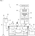
- Fig. 1 is a diagram showing a configuration of an organ preservation device 1 that includes an organ container 20 provided with a leak valve 10 according to one embodiment.
- the organ preservation device 1 is a device for use in an organ transplant operation and for temporarily preserving an organ 9 removed from the donor ex vivo until the organ 9 is transplanted into the recipient.
- the organ 9 include a liver, a kidney, a heart, and a pancreas. It is however noted that the organ 9 to be preserved in the organ preservation device 1 may be any other organ, or may be part of an organ.
- the organ preservation device 1 preserves the organ 9 while perfusing blood vessels in the organ 9 with a preservation solution such as a physiological saline.
- a catheter is connected to each of the arteries and veins of the organ 9.
- the catheter connected to an artery of the organ 9 is referred to as a "first catheter 91.”
- the catheter connected to a vein of the organ 9 is referred to as a "second catheter 92.”
- the preservation solution flows into the artery of the organ 9 through the first catheter 91 and are discharged from the vein through the second catheter 92 after flowing through capillary vessels of the organ 9.
- the "first catheter 91" through which the preservation solution flows into may be connected to a vein of the organ 9.
- the "first catheter 91" may be connected to a portal vein of the venous system.
- the "second catheter 92" through which the preservation solution is discharged does not necessarily have to be connected to the organ 9.
- the preservation solution may be discharged as-is from the vein of the organ 9 and stored in the organ container 20 described later, and one end of the “second catheter” may be positioned at the site of the storage to allow the discharge of the preservation solution from the other end of the "second catheter "to the space outside the organ container 20.
- the organ preservation device 1 includes the organ container 20, a liquid supplier 30, a drainage 40, a pressure reducer 50, and a controller 60.
- the organ container 20 is a preservation container for preserving a biological sample such as a removed organ.
- the organ container 20 includes a container body 21 and a container lid 22.
- the container body 21 is a cup-shaped member that opens upward.
- the container lid 22 is a member that covers the opening at the top of the container body 21.
- the container body 21 and the container lid 22 may be formed of a resin.
- Packing 23 having elasticity is provided at the joint of the container body 21 and the container lid 22.
- the packing 23 is arranged along the entire periphery of the edge of the opening of the container body 21.
- the organ container 20 is sealed when the container body 21 and the container lid 22 are fixed to each other by a plurality of (in the present embodiment, two) hooks 221 provided on the container lid 22. Note that the number of hooks 221 may be three or more.
- the container body 21 includes a first flow-path joint 211 and a second flow-path joint 212.
- Each of the first flow-path joint 211 and the second flow-path joint 212 penetrates the side wall of the container body 21 in the horizontal direction and allows the connection of catheters from the inside and outside of the container body 21.
- the container lid 22 includes an intake-tube joint 222 and a leak-valve joint 223. Each of the intake-tube joint 222 and the leak-valve joint 223 penetrates the container lid 22 in the up-down direction.
- the internal space of the organ container 20 communicates with the interior of an intake tube 51 described later when the intake tube 51 is connected to the intake-tube joint 22 from the outside of the container lid 22.
- the leak valve 10 described later is connected to the leak-valve joint 223.
- the internal space of the leak valve 10 and the internal space of the organ container 20 communicate with each other when a port 75 of the leak valve 10 described later is connected to the leak-valve j oint 223. Note that a specific configuration of the leak valve 10 will be described later.
- an organ holder 24 is arranged inside the organ container 20.
- the organ holder 24 holds the organ 9 in the organ container 20.
- the organ holder 24 includes a flexibly deformable holding sheet 241 and a support member 242.
- the edge of the holding sheet 241 is supported by the support member 242 that is fixedly attached to the bottom surface of the container body 21. This allows the holding sheet 241 to be maintained in an approximately horizontal open condition.
- the organ 9 is placed on the upper surface of the holding sheet 241.
- the holding sheet 241 becomes deformed along the surface shape of the organ 9. This prevents deformation of the organ 9 and allows the organ 9 to be held with reduced loads applied to the organ 9.
- the material for the holding sheet 241 may be a resin having bioadaptability, sterilization retention properties, and flexibility.
- Examples of the material for the holding sheet 241 include polypropylene, polyethylene, polyurethane, polyvinylidene chloride, polystyrene, elastomeric resins, silicon, rubber, gel materials, and polyamide.
- water or a preservation solution is stored on the bottom of the organ container 20.
- moisture becomes more susceptible to be vaporized with ease from the organ 9 by reducing pressure in the space of the organ container 20 as will be described later, but the storage of water or a preservation solution on the bottom of the organ container 20 reduces the risk of drying of the organ 9.
- the drying of the organ 9 may be prevented by immersing the holding sheet 241 in water or a preservation solution.
- the top of the organ 9 may be covered with a sheet that has been immersed in water or a preservation solution in order to further prevent the drying of the organ 9.
- the liquid supplier 30 supplies a preservation solution to the organ 9.
- the liquid supplier 30 according to the present embodiment includes a liquid reservoir 31 and a supply tube 32.
- the liquid reservoir 31 stores a preservation solution before supply to the organ 9.
- the liquid reservoir 31 according to the present embodiment is a pouch bag (so-called drip bag) in which a preservation solution is stored.
- the liquid reservoir 31 may be in any other form such as a so-called tank or bottle as long as it serves as a container capable of storing a preservation solution.
- the liquid reservoir 31 is held at a position higher than the organ 9 held in the organ container 20 by a bag holder 33.
- the supply tube 32 is a tube for supplying a preservation solution from the liquid reservoir 31 to the organ 9 held in the organ container 20.
- the upstream end of the supply tube 32 is connected to the liquid reservoir 31.
- the downstream end of the supply tube 32 is detachably connected to the first flow-path joint 211 provided at the container body 21 from the outside of the container body 21.
- the other end of the first catheter 91 whose one end is connected to the artery of the organ 9 is detachably connected to the inside of the first flow-path joint 211. This forms a flow path for the preservation solution that flows from the liquid reservoir 31 through the supply tube 32, the first flow-path joint 211, and the first catheter 91 into the organ 9.
- the path of the supply tube 32 is provided with no supply pump.
- a height difference between the liquid reservoir 31 and the organ 9 causes the preservation solution to flow from the liquid reservoir 31 through the supply tube 32 into the artery of the organ 9.
- the omission of a supply pump simplifies the device configuration and reduces pressure loads applied to the organ 9 as a result of inflow of the preservation solution.
- the drainage 40 includes a drainage tube 41 and a drain tank 42.
- the drainage tube 41 is a tube for discharging the preservation solution from the organ 9 held in the organ container 20.
- the downstream end of the drainage tube 41 is connected to the drain tank 42.
- the upstream end of the drainage tube 41 is detachably connected to the outside of the second flow-path joint 212 provided at the container body 21.
- the other end of the second catheter 92 whose one end is connected to the vein of the organ 9 is detachably connected to the inside of the second flow-path joint 212. This forms a flow path for the preservation solution that is discharged from the organ 9 through the second catheter 92, the second flow-path joint 212, and the drainage tube 41 into the drain tank 42.
- the preservation solution discharged from the vein of the organ 9 flows through the second catheter 92, the second flow-path joint 212, and the drainage tube 41 and is collected in the drain tank 42.
- the preservation solution collected in the drain tank 42 may be circulated to the liquid reservoir 31 and reused.
- the pressure reducer 50 is arranged outside the organ container 20.
- the pressure reducer 50 is a pressure-reducing mechanism for sucking gas from the inside of the organ container 20 and reducing pressure in the organ container.
- the pressure reducer 50 according to the present embodiment includes the intake tube 51, a pressure-reducing pump 52, a regulator 53, and an on-off valve 54.
- the upstream end of the intake tube 51 is detachably connected to the intake-tube joint 222 provided at the container lid 22.
- the downstream end of the intake tube 51 is connected to the pressure-reducing pump 52.
- the regulator 53 and the on-off valve 54 are provided in the path of the intake tube 51. Accordingly, when the pressure-reducing pump 52 is operated, gas is sucked from the internal space of the organ container 20 through the intake tube 51 and discharged to the external space. As a result, atmospheric pressure in the organ container 20 is reduced.
- the regulator 53 raises the negative pressure generated by the pressure-reducing pump 52 to a higher fixed negative pressure (with a smaller absolute value when expressed by the gage pressure).
- the on-off valve 54 is a valve for switching an airflow in the intake tube 51 between an open state and a stopped state.
- the controller 60 controls the operations of the pressure reducer 50.
- the controller 60 may be configured as an electronic circuit board or a computer that includes a processor such as a CPU and memory such as a RAM.
- the controller 60 is electrically connected to each of the pressure-reducing pump 52, the regulator 53, and the on-off valve 54 described above.
- the controller 60 controls the operations of these components in accordance with preset programs. Accordingly, atmospheric pressure in the organ container 20 is regulated.
- Fig. 2 is a longitudinal sectional view of the leak valve 10. Atmospheric pressure in the space outside an intake port 710 is hereinafter referred to as to an "outside pressure.” Also, atmospheric pressure in the space outside a communicating port 730 (i.e., the space inside the organ container 20) is hereinafter referred to as an "inside pressure.”
- the diagram on the left side in Fig. 2 shows the leak valve 10 when the outside pressure and the inside pressure are approximately the same. That is, the diagram on the left side in Fig. 2 shows the leak valve 10 when an atmospheric pressure difference between the outside pressure and the inside pressure is less than or equal to a predetermined value.
- the diagram on the right side in Fig. 2 shows the leak valve 10 when the inside pressure is lower than the outside pressure and the atmospheric pressure difference between the outside pressure and the inside pressure is greater than the predetermined value.
- the posture of the leak valve 10 during use is not limited to this orientation.
- the leak valve 10 may be used in such a posture that the communicating port 730 and the intake port 710 are arranged side by side in the horizontal direction (in positions at the same level of height).
- the upper side means “one side”
- the lower side means the “other side.”
- the leak valve 10 includes a case 70 and a moving part 80.
- the case 70 is a member having an internal space.
- the case 70 has a cylinder-like outside shape.
- the case 70 includes a disk-like upper plate 71, a cylinder-like side wall 72 extending downward from the outer edge of the upper plate 71, and a bottom 73 that covers an opening at the bottom of the side wall 72.
- the upper plate 71 includes the intake port 710 in the center in a top view, the intake port 710 being a through hole that penetrates the upper plate vertically. That is, the intake port 710 is arranged on the upper side (one side) of the case 70.
- the leak valve 10 During use of the leak valve 10, the leak valve 10, except part of the port 75 described later, is arranged outside the organ container 20.
- the intake port 710 is arranged in the space outside the organ container 20 and communicates with the space outside the organ container 20.
- the lower surface of the upper plate 71 is provided with a ring-shaped groove 711 that is recessed upward and located in a position surrounding the intake port 710. Then, a ring-shaped seal member 74 is provided to fit in the groove 711.
- the seal member 74 is fixedly attached to the lower surface of the upper plate 71. That is, the seal member 74 is fixedly attached to the inner surface on the upper side (one side) of the case 70.
- the seal member 74 is arranged in a position surrounding the intake port 710. Specifically, the upper surface side of the seal member 74 is housed inside the groove 711.
- the seal member 74 may be fitted in and fixedly attached to the groove 711 while becoming elastically deformed, or may be bonded to the lower surface of the upper plate 71.
- the bottom 73 has a cylinder-like outside shape.
- the bottom 73 has a communicating port 730 in the center in a bottom view, the communicating port being a through hole that penetrates the bottom vertically.
- the inner surface of the bottom 73 has a conical shape that tapers down from the lower end portion of the side wall 72 toward the communicating port 730. Note that the bottom 73 may have a disk-like shape, like the upper plate 71.
- the port 75 is mounted at the communicating port 730.
- the port 75 corresponds to a cylinder-like portion that extends downward from the communicating port 730.
- the joint of the upper end of the port 75 and the communicating port 730 is configured to prevent air leakage.
- the port 75 and the bottom 73 of the case 70 may be formed as an integral unit.
- the port 75 is inserted in and fixed to the leak-valve joint 223 provided at the container lid 22 of the organ container 20.
- the communicating port 730 of the leak valve 10 and the internal space of the organ container 20 communicate with each other.
- the outer peripheral surface of the port 75 and the leak-valve joint 223 are brought into tight contact with each other and fixed to prevent gas leakage.
- the port 75 and the leak-valve joint 223 may be fixed with an adhesive, or the leak-valve joint 223 may be provided with an adapter that prevents gas leakage.
- the moving part 80 includes an opening and closing plate 81, a shaft 82, a flange member 83, and a coil spring 84.
- the moving part 80 is movable in the up-down direction relative to the case 70.
- the opening and closing plate 81 is arranged in a closed position P1 as shown on the left side in Fig. 2 .
- the diagram on the right side in Fig. 2 shows a state in which the opening and closing plate 81 is arranged in an open position P2 located below the closed position P1.
- the opening and closing plate 81 is a disk-like member.
- the opening and closing plate 81 is arranged approximately parallel to the lower surface of the upper plate 71 of the case 70. That is, the opening and closing plate 81 expands perpendicularly to the up-down direction.
- the shaft 82 is a column-like member extending in the up-down direction.
- the upper-side (one-side) end of the shaft 82 is arranged outside and above the case 70.
- the lower-side (other-side) end of the shaft 82 is fixed to the central portion of the opening and closing plate 81 in the internal space of the case 70.
- the opening and closing plate 81 expands in a direction perpendicular to the shaft 82.
- the flange member 83 is fixed to the shaft 82 outside and above the case 70.
- the flange member 83 expands in a direction perpendicular to the shaft 82.
- the coil spring 84 is a biasing member that biases the opening and closing plate 81.
- the coil spring 84 is arranged between the upper surface of the upper plate 71 of the case 70 and the lower surface of the flange member 83.
- the coil spring 84 is arranged so as to cover around the shaft 82.
- a distance between the upper surface of the upper plate 71 and the lower surface of the flange member 83 is designed to become shorter than the natural length of the coil spring 84 when the opening and closing plate 81 is located in the closed position P1.
- the coil spring 84 is thus always in a compressed state. Accordingly, the coil spring 84 applies force in a direction causing the upper surface of the upper plate 71 and the lower surface of the flange member 83 to stay away from each other in the up-down direction. In this case, the coil spring 84 biases the flange member 83 in a direction to the upper side (one side) relative to the case 70.
- the coil spring 84 consequently biases the opening and closing plate 81 in a direction to the upper side (one side) relative to the case 70.
- the shaft 82 serves as a bolt having an outer peripheral surface provided with a screw thread.
- the flange member 83 serves as a nut having a through hole 830 that penetrates the flange member vertically in the up-down direction and that has an inner peripheral surface provided with a thread groove. Accordingly, it is possible to easily change the position in the up-down direction of the flange member 83 relative to the shaft 82 by rotating the flange member 83 relative to the shaft 82. That is, it is possible to easily change the biasing force exerted by the coil spring 84 by changing the distance between the upper surface of the upper plate 71 and the lower surface of the flange member 83 when the opening and closing plate 81 is located in the closed position P1.
- the opening and closing plate 81 isolates a first space S1 and a second space S2 from each other in the interior of the case 70, the first space S1 communicating with the external space above the case 70 through the intake port 710, the second space S2 communicating with the internal space of the organ container 20 through the communicating port 730 and the port 75.
- the first space S1 is a space surrounded by the lower surface of the upper plate 71 of the case 70, the seal member 74, and a first surface 811 of the opening and closing plate 81.
- the second space S2 is an internal space of the case 70 excluding the first space S1.
- the opening and closing plate 81 moves perpendicularly to the intake port 710 and the seal member 74.
- the opening and closing plate 81 located in the closed position P1 uniformly presses the entire periphery of the seal member 74. Accordingly, interstices are less likely to be created at the joint between the opening and closing plate 81 and the seal member 74.
- Fig. 3 is a diagram showing the force acting on the opening and closing plate 81 at the time of reducing pressure in the internal space of the organ container 20.
- Fig. 4 is a diagram showing pressure inside the organ container 20 provided with the leak valve 10 during operation of the pressure reducer 50.
- the force applied to the opening and closing plate 81 in the up-down direction is indicated by arrows.
- the length of each arrow indicates the magnitude of the force.
- atmospheric pressure in the first space S1 is applied to a region of the first surface 811 that is located inward of the seal member 74.
- atmospheric pressure in the second space S2 is applied to the entire second surface 812 and a region of the first surface 811 that is located outward of the seal member 74.
- the coil spring 84 biases the opening and closing plate 81 upward via the shaft 82.
- the atmospheric pressure in the organ container 20 (inside pressure) is the same atmospheric pressure as the outside pressure
- the atmospheric pressure in the first space S1 and the atmospheric pressure in the second space S2 are the same.
- the atmospheric pressure applied to the first surface 811 of the opening and closing plate 81 is almost equal to the atmospheric pressure applied to the second surface 812.
- the biasing force exerted by the coil spring 84 is further applied to the opening and closing plate 81, an upward force applied to the opening and closing plate 81 exceeds a downward force applied to the opening and closing plate 81. Accordingly, the opening and closing plate 81 does not move from the closed position P1.
- the atmospheric pressure in the second space S2 becomes lower than the atmospheric pressure in the first space S1.
- the downward force applied to the opening and closing plate 81 exceeds the upward force applied to the opening and closing plate 81. That is, the atmospheric pressure applied to the first surface 811 exceeds a total of the atmospheric pressure applied to the second surface 812 and the biasing force exerted by the coil spring 84. In this case, the opening and closing plate 81 moves downward and is located in the open position P2.
- the opening and closing plate 81 moves repeatedly between the open position P2 and the closed position P1 to maintain the pressure in the organ container 20 at around the predetermined pressure.
- the "predetermined pressure" at which the opening and closing plate 81 starts to move from the closed position P1 to maintain pressure is determined by the biasing force of the coil spring 84 and the area of the first surface 811 that comes in contact with the first space S1. Therefore, adjusting these elements makes it possible to maintain the pressure in the organ container 20 at a desired pressure.
- Fig. 4 is a diagram showing the result of experiment conducted using the organ container 20 provided with the leak valve 10 according to the present embodiment.
- output of the regulator 53 reduced by the pressure reducer 50 is set to be -150 mmHg, and the on-off valve 54 opens and closes to change the pressure in the organ container 20.
- the on-off valve 54 opens to start the sucking of gas via the pressure-reducing pump 52 and the regulator 53.
- the on-off valve 54 closes to stop the sucking of the gas.
- the use of the leak valve 10 allows the pressure in the organ container 20 to be maintained within the range of approximately -20 mmHg to -18 mmHg during a period in which the pressure reducer 50 reduces pressure using a target pressure of -150 mmHg.
- the use of the leak valve 10 allows the pressure in the organ container 20 to be maintained at a predetermined pressure without using any complex control mechanism.
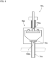
- Fig. 5 is a longitudinal sectional view of a leak valve 10A according to a first variation.
- the leak valve 10A includes a filter 76A provided at a communicating port 730A.
- the presence of the filter reduces the risk of mixing of foreign materials such as fine dust into the organ container 20 through the communicating port 730A and a port 75A, the foreign materials being included in air applied from the external space into the internal space of a case 70A through an intake port 710A.
- Fig. 6 is a longitudinal sectional view of a leak valve 10B according to a second variation.
- the leak valve 10B includes a coil spring 84B that is provided inside a case 70B and that biases an opening and closing plate 81B.
- the opening and closing plate 81B is biased upward by the coil spring 84B.
- a moving part 80B has a shorter protruding portion that protrudes to the outside of the case 70B.
- the biasing member (coil spring 84B) for biasing the opening and closing plate 81B may be arranged inside the case 70B.
- the case 70 has a column-like outside shape
- the present invention is not limited to this example.
- the case 70 may have any other shape such as a rectangular parallelepiped shape.
- leak valve 10 is mounted on the container lid 22 of the organ container 20
- the present invention is not limited to this example.
- the leak valve 10 may be mounted on the container body 21of the organ container 20.
- the leak valve 10 is mounted directly on the organ container 20, the present invention is not limited to this example.
- the leak valve 10 may be mounted on a piping circuit that controls atmospheric pressure inside the organ container 20.
- the leak valve 10 may be mounted on the intake tube 51 of the pressure reducer 50.
- the biasing member for biasing the opening and closing plate may be any other elastic member such as a plate spring or rubber.
- the preservation container with the leak valve 10 mounted thereon is the organ container 20 for placing a removed organ therein
- the present invention is not limited to this example.
- the preservation container with a leak valve mounted thereon may be any other container for holding a biological sample (e.g., cells) other than an organ.
- the organ preservation device 1 includes one supply tube 32, one first catheter 91, one drainage tube 41, and one second catheter 92.
- the organ preservation device 1 may include a plurality of supply tubes 32 and a plurality of first catheters 91 depending on the number of arteries of the organ 9.
- the organ preservation device 1 may also include a plurality of drainage tubes 41 and a plurality of second catheters 92 depending on the number of veins of the organ 9.
Landscapes
- Life Sciences & Earth Sciences (AREA)
- Engineering & Computer Science (AREA)
- Health & Medical Sciences (AREA)
- Dentistry (AREA)
- General Health & Medical Sciences (AREA)
- Wood Science & Technology (AREA)
- Zoology (AREA)
- Environmental Sciences (AREA)
- General Engineering & Computer Science (AREA)
- Mechanical Engineering (AREA)
- Agricultural Chemicals And Associated Chemicals (AREA)
- Self-Closing Valves And Venting Or Aerating Valves (AREA)
Abstract
Description
- The present invention relates to a leak valve for adjusting pressure inside a preservation container that preserves a biological sample such as an organ ex vivo.
- In organ transplant operations such as liver transplantation, an organ removed from the donor is temporarily preserved ex vivo until the organ is transplanted into the recipient. At this time, the organ is placed in a preservation container and perfused with a preservation solution in order to prevent the organ from becoming ischemic. An example of a conventional system for preserving an organ ex vivo is disclosed in Patent Literature (PTL) 1.
- PTL 1:
Japanese Unexamined Patent Application Publication (Translation of PCT Application) No.2017-518301 - In the organ care system disclosed in
PTL 1, a liver during perfusion is placed in an organ chamber (104). In the case of perfusion of such an organ placed in the preservation container, it is preferable that atmospheric pressure applied to the organ be adjusted in order to improve the flow of a preservation solution in the organ. Specifically, the flow of the preservation solution is known to be improved by reducing pressure to expand blood vessels. Similar studies on pressure application are carried out not only in the field of organs but also in the field of cell culture. - However, negative pressure applied to an organ or cells is weak on the order of about 0 mmHg to -30 mmHg, and in order to accurately maintain pressure within this pressure range, a complex control mechanism has been conventionally necessary.
- The present invention has been made in light of such circumstances, and it is an object of the present invention to provide a technique for maintaining pressure in a preservation container that preserves a biological sample at an appropriate negative pressure without using any complex control mechanism.
- To solve the problem described above, a first aspect of the present application is a leak valve for adjusting pressure inside a preservation container for preserving a biological sample. The leak valve includes a case having a communicating port and an intake port, the communicating port communicating with an interior of the preservation container, the intake port communicating with an external space, an opening and closing plate arranged in the case, and a biasing member that biases the opening and closing plate. The opening and closing plate is movable between a closed position in which a first space communicating with the intake port and a second space communicating with the communicating port are isolated from each other in the case, and an open position in which the first space and the second space communicate with each other. The biasing member biases the opening and closing plate in a direction from the open position toward the closed position, and the opening and closing plate is pressed toward the closed position by a biasing force of the biasing member when atmospheric pressure in the communicating port and atmospheric pressure in the intake port are approximately the same.
- A second aspect of the present application is the leak valve according to the first aspect that further includes a ring-shaped seal member. The intake port is arranged on one side of the case, the seal member is fixed to an inner surface of the case on the one side to surround the intake port, and when the opening and closing plate is located in the closed position, a surface of the opening and closing plate on the one side comes in tight contact with a surface of the seal member on the other side.
- A third aspect of the present application is the leak valve according to the first or second aspect that further includes a shaft whose end on the one side is arranged outside the case and whose end on the other side is fixed to the opening and closing plate in an internal space of the case. The intake port is arranged on the one side of the case, the shaft penetrates an interior of the intake port, the opening and closing plate expands in a direction perpendicular to the shaft, and the biasing member biases the opening and closing plate toward the one side in a direction of extension of the shaft.
- A fourth aspect of the present application is the leak valve according to the third aspect that further includes a flange member fixed to the shaft outside the case and expanding in a direction perpendicular to the shaft. The biasing member is a coil spring that is arranged around the shaft and between the flange member and an outer surface of the case on the one side.
- A fifth aspect of the present application is the leak valve according to the fourth aspect, in which the shaft is a bolt having an outer peripheral surface provided with a screw thread, and the flange member is a nut having a through hole whose inner peripheral surface is provided with a thread groove.
- A sixth aspect of the present application is the leak valve according to any one of the first to fifth aspects that further includes a filter arranged at the communicating port.
- A seventh aspect of the present application is a preservation container for preserving a biological sample. The preservation container includes a cup-shaped container body that opens upward, a container lid that covers an opening at a top of the container body, and the leak valve according to any one of
claims 1 to 6, the leak valve being mounted on either the container body or the container lid. - According to the first to seventh aspects of the present application, it is possible to reduce the possibility that the pressure in the preservation container may become lower than the predetermined pressure, without using any complex control mechanism.
- In particular, according to the second aspect of the present application, it is possible to reduce the risk of gas leakage between the first space and the second space at the time of closing the opening and closing plate.
- In particular, according to the fifth aspect of the present application, it is possible to easily change the length of the coil spring, i.e., the biasing force exerted by the coil spring, by changing the position of the nut relative to the bolt.
- In particular, according to the sixth aspect of the present application, it is possible to reduce the risk of mixing of foreign matters into the preservation container via the leak valve.
-
-
Fig. 1 is a diagram showing a configuration of an organ preservation device. -
Fig. 2 is a sectional view of a leak valve. -
Fig. 3 is a diagram showing the force acting on an opening and closing plate at the time of reducing pressure in an organ container. -
Fig. 4 is a diagram showing pressure inside the organ container during activation of a pressure-reducing mechanism. -
Fig. 5 is a sectional view of a leak valve according to a variation. -
Fig. 6 is a sectional view of a leak valve according to another variation. - Hereinafter, an embodiment of the present invention will be described with reference to the drawings.
- In the present application, the "donor" and the "recipient" may be humans or may be non-human animals. That is, the "organ" according to the present application may be a human organ or may be an organ of a non-human animal. Examples of the non-human animal include rodents such as mice and rats, ungulates such as pigs, goats, and sheep, non-human primates such as chimpanzees, and any other non-human mammal, and the non-human animal may be a non-mammalian animal.
-
Fig. 1 is a diagram showing a configuration of anorgan preservation device 1 that includes anorgan container 20 provided with aleak valve 10 according to one embodiment. - The
organ preservation device 1 is a device for use in an organ transplant operation and for temporarily preserving anorgan 9 removed from the donor ex vivo until theorgan 9 is transplanted into the recipient. Examples of theorgan 9 include a liver, a kidney, a heart, and a pancreas. It is however noted that theorgan 9 to be preserved in theorgan preservation device 1 may be any other organ, or may be part of an organ. Theorgan preservation device 1 preserves theorgan 9 while perfusing blood vessels in theorgan 9 with a preservation solution such as a physiological saline. - In the transplant of the
organ 9, a catheter is connected to each of the arteries and veins of theorgan 9. Hereinafter, the catheter connected to an artery of theorgan 9 is referred to as a "first catheter 91." The catheter connected to a vein of theorgan 9 is referred to as a "second catheter 92." The preservation solution flows into the artery of theorgan 9 through thefirst catheter 91 and are discharged from the vein through thesecond catheter 92 after flowing through capillary vessels of theorgan 9. Alternatively, the "first catheter 91" through which the preservation solution flows into may be connected to a vein of theorgan 9. For example, in the case where theorgan 9 is a liver, the details of which will be described later, the "first catheter 91" may be connected to a portal vein of the venous system. The "second catheter 92" through which the preservation solution is discharged does not necessarily have to be connected to theorgan 9. For example, the preservation solution may be discharged as-is from the vein of theorgan 9 and stored in theorgan container 20 described later, and one end of the "second catheter" may be positioned at the site of the storage to allow the discharge of the preservation solution from the other end of the "second catheter "to the space outside theorgan container 20. - As shown in
Fig. 1 , theorgan preservation device 1 according to the present embodiment includes theorgan container 20, aliquid supplier 30, adrainage 40, apressure reducer 50, and acontroller 60. - The
organ container 20 is a preservation container for preserving a biological sample such as a removed organ. Theorgan container 20 includes acontainer body 21 and acontainer lid 22. Thecontainer body 21 is a cup-shaped member that opens upward. Thecontainer lid 22 is a member that covers the opening at the top of thecontainer body 21. For example, thecontainer body 21 and thecontainer lid 22 may be formed of a resin. -
Packing 23 having elasticity is provided at the joint of thecontainer body 21 and thecontainer lid 22. The packing 23 is arranged along the entire periphery of the edge of the opening of thecontainer body 21. Theorgan container 20 is sealed when thecontainer body 21 and thecontainer lid 22 are fixed to each other by a plurality of (in the present embodiment, two) hooks 221 provided on thecontainer lid 22. Note that the number ofhooks 221 may be three or more. - As shown in
Fig. 1 , thecontainer body 21 includes a first flow-path joint 211 and a second flow-path joint 212. Each of the first flow-path joint 211 and the second flow-path joint 212 penetrates the side wall of thecontainer body 21 in the horizontal direction and allows the connection of catheters from the inside and outside of thecontainer body 21. - The
container lid 22 includes an intake-tube joint 222 and a leak-valve joint 223. Each of the intake-tube joint 222 and the leak-valve joint 223 penetrates thecontainer lid 22 in the up-down direction. The internal space of theorgan container 20 communicates with the interior of anintake tube 51 described later when theintake tube 51 is connected to the intake-tube joint 22 from the outside of thecontainer lid 22. - The
leak valve 10 described later is connected to the leak-valve joint 223. The internal space of theleak valve 10 and the internal space of theorgan container 20 communicate with each other when aport 75 of theleak valve 10 described later is connected to the leak-valve j oint 223. Note that a specific configuration of theleak valve 10 will be described later. - In the case of placing the
organ 9 inside theorgan container 20, anorgan holder 24 is arranged inside theorgan container 20. Theorgan holder 24 holds theorgan 9 in theorgan container 20. Theorgan holder 24 includes a flexiblydeformable holding sheet 241 and asupport member 242. The edge of the holdingsheet 241 is supported by thesupport member 242 that is fixedly attached to the bottom surface of thecontainer body 21. This allows the holdingsheet 241 to be maintained in an approximately horizontal open condition. - The
organ 9 is placed on the upper surface of the holdingsheet 241. When theorgan 9 is placed, the holdingsheet 241 becomes deformed along the surface shape of theorgan 9. This prevents deformation of theorgan 9 and allows theorgan 9 to be held with reduced loads applied to theorgan 9. - The material for the holding
sheet 241 may be a resin having bioadaptability, sterilization retention properties, and flexibility. Examples of the material for the holdingsheet 241 include polypropylene, polyethylene, polyurethane, polyvinylidene chloride, polystyrene, elastomeric resins, silicon, rubber, gel materials, and polyamide. - As shown in
Fig. 1 , water or a preservation solution is stored on the bottom of theorgan container 20. This prevents theorgan 9 from drying in theorgan container 20. In particular, moisture becomes more susceptible to be vaporized with ease from theorgan 9 by reducing pressure in the space of theorgan container 20 as will be described later, but the storage of water or a preservation solution on the bottom of theorgan container 20 reduces the risk of drying of theorgan 9. Note that the drying of theorgan 9 may be prevented by immersing the holdingsheet 241 in water or a preservation solution. As another alternative, the top of theorgan 9 may be covered with a sheet that has been immersed in water or a preservation solution in order to further prevent the drying of theorgan 9. - The
liquid supplier 30 supplies a preservation solution to theorgan 9. Theliquid supplier 30 according to the present embodiment includes aliquid reservoir 31 and asupply tube 32. - The
liquid reservoir 31 stores a preservation solution before supply to theorgan 9. Theliquid reservoir 31 according to the present embodiment is a pouch bag (so-called drip bag) in which a preservation solution is stored. Note that theliquid reservoir 31 may be in any other form such as a so-called tank or bottle as long as it serves as a container capable of storing a preservation solution. Theliquid reservoir 31 is held at a position higher than theorgan 9 held in theorgan container 20 by abag holder 33. - The
supply tube 32 is a tube for supplying a preservation solution from theliquid reservoir 31 to theorgan 9 held in theorgan container 20. The upstream end of thesupply tube 32 is connected to theliquid reservoir 31. The downstream end of thesupply tube 32 is detachably connected to the first flow-path joint 211 provided at thecontainer body 21 from the outside of thecontainer body 21. The other end of thefirst catheter 91 whose one end is connected to the artery of theorgan 9 is detachably connected to the inside of the first flow-path joint 211. This forms a flow path for the preservation solution that flows from theliquid reservoir 31 through thesupply tube 32, the first flow-path joint 211, and thefirst catheter 91 into theorgan 9. - In the present embodiment, the path of the
supply tube 32 is provided with no supply pump. A height difference between theliquid reservoir 31 and theorgan 9 causes the preservation solution to flow from theliquid reservoir 31 through thesupply tube 32 into the artery of theorgan 9. In this way, the omission of a supply pump simplifies the device configuration and reduces pressure loads applied to theorgan 9 as a result of inflow of the preservation solution. - The
drainage 40 includes adrainage tube 41 and adrain tank 42. Thedrainage tube 41 is a tube for discharging the preservation solution from theorgan 9 held in theorgan container 20. The downstream end of thedrainage tube 41 is connected to thedrain tank 42. The upstream end of thedrainage tube 41 is detachably connected to the outside of the second flow-path joint 212 provided at thecontainer body 21. The other end of thesecond catheter 92 whose one end is connected to the vein of theorgan 9 is detachably connected to the inside of the second flow-path joint 212. This forms a flow path for the preservation solution that is discharged from theorgan 9 through thesecond catheter 92, the second flow-path joint 212, and thedrainage tube 41 into thedrain tank 42. That is, the preservation solution discharged from the vein of theorgan 9 flows through thesecond catheter 92, the second flow-path joint 212, and thedrainage tube 41 and is collected in thedrain tank 42. In the case where theliquid reservoir 31 is a tank for storing a preservation solution, the preservation solution collected in thedrain tank 42 may be circulated to theliquid reservoir 31 and reused. - The
pressure reducer 50 is arranged outside theorgan container 20. Thepressure reducer 50 is a pressure-reducing mechanism for sucking gas from the inside of theorgan container 20 and reducing pressure in the organ container. As shown inFig. 1 , thepressure reducer 50 according to the present embodiment includes theintake tube 51, a pressure-reducingpump 52, aregulator 53, and an on-offvalve 54. - The upstream end of the
intake tube 51 is detachably connected to the intake-tube joint 222 provided at thecontainer lid 22. Thus, the upstream end of theintake tube 51 communicates with the internal space of theorgan container 20. The downstream end of theintake tube 51 is connected to the pressure-reducingpump 52. Theregulator 53 and the on-offvalve 54 are provided in the path of theintake tube 51. Accordingly, when the pressure-reducingpump 52 is operated, gas is sucked from the internal space of theorgan container 20 through theintake tube 51 and discharged to the external space. As a result, atmospheric pressure in theorgan container 20 is reduced. Theregulator 53 raises the negative pressure generated by the pressure-reducingpump 52 to a higher fixed negative pressure (with a smaller absolute value when expressed by the gage pressure). The on-offvalve 54 is a valve for switching an airflow in theintake tube 51 between an open state and a stopped state. - The
controller 60 controls the operations of thepressure reducer 50. For example thecontroller 60 may be configured as an electronic circuit board or a computer that includes a processor such as a CPU and memory such as a RAM. Thecontroller 60 is electrically connected to each of the pressure-reducingpump 52, theregulator 53, and the on-offvalve 54 described above. Thecontroller 60 controls the operations of these components in accordance with preset programs. Accordingly, atmospheric pressure in theorgan container 20 is regulated. - Next, a configuration of the
leak valve 10 will be described with reference toFig. 2. Fig. 2 is a longitudinal sectional view of theleak valve 10. Atmospheric pressure in the space outside anintake port 710 is hereinafter referred to as to an "outside pressure." Also, atmospheric pressure in the space outside a communicating port 730 (i.e., the space inside the organ container 20) is hereinafter referred to as an "inside pressure." The diagram on the left side inFig. 2 shows theleak valve 10 when the outside pressure and the inside pressure are approximately the same. That is, the diagram on the left side inFig. 2 shows theleak valve 10 when an atmospheric pressure difference between the outside pressure and the inside pressure is less than or equal to a predetermined value. The diagram on the right side inFig. 2 shows theleak valve 10 when the inside pressure is lower than the outside pressure and the atmospheric pressure difference between the outside pressure and the inside pressure is greater than the predetermined value. - The following description is given using the up-down direction, assuming that the side closer to the
intake port 710 relative to the communicatingport 730 is the upper side. However, the posture of theleak valve 10 during use is not limited to this orientation. Theleak valve 10 may be used in such a posture that the communicatingport 730 and theintake port 710 are arranged side by side in the horizontal direction (in positions at the same level of height). In the present embodiment, the upper side means "one side" and the lower side means the "other side." - The
leak valve 10 includes acase 70 and a movingpart 80. - As shown in
Fig. 2 , thecase 70 is a member having an internal space. In the present embodiment, thecase 70 has a cylinder-like outside shape. Specifically, thecase 70 includes a disk-likeupper plate 71, a cylinder-like side wall 72 extending downward from the outer edge of theupper plate 71, and a bottom 73 that covers an opening at the bottom of theside wall 72. - The
upper plate 71 includes theintake port 710 in the center in a top view, theintake port 710 being a through hole that penetrates the upper plate vertically. That is, theintake port 710 is arranged on the upper side (one side) of thecase 70. - During use of the
leak valve 10, theleak valve 10, except part of theport 75 described later, is arranged outside theorgan container 20. Thus, theintake port 710 is arranged in the space outside theorgan container 20 and communicates with the space outside theorgan container 20. - The lower surface of the
upper plate 71 is provided with a ring-shapedgroove 711 that is recessed upward and located in a position surrounding theintake port 710. Then, a ring-shapedseal member 74 is provided to fit in thegroove 711. - The
seal member 74 is fixedly attached to the lower surface of theupper plate 71. That is, theseal member 74 is fixedly attached to the inner surface on the upper side (one side) of thecase 70. Theseal member 74 is arranged in a position surrounding theintake port 710. Specifically, the upper surface side of theseal member 74 is housed inside thegroove 711. Theseal member 74 may be fitted in and fixedly attached to thegroove 711 while becoming elastically deformed, or may be bonded to the lower surface of theupper plate 71. - The bottom 73 has a cylinder-like outside shape. The bottom 73 has a communicating
port 730 in the center in a bottom view, the communicating port being a through hole that penetrates the bottom vertically. The inner surface of the bottom 73 has a conical shape that tapers down from the lower end portion of theside wall 72 toward the communicatingport 730. Note that the bottom 73 may have a disk-like shape, like theupper plate 71. - The
port 75 is mounted at the communicatingport 730. Theport 75 corresponds to a cylinder-like portion that extends downward from the communicatingport 730. The joint of the upper end of theport 75 and the communicatingport 730 is configured to prevent air leakage. Note that theport 75 and the bottom 73 of thecase 70 may be formed as an integral unit. - During use of the
leak valve 10, theport 75 is inserted in and fixed to the leak-valve joint 223 provided at thecontainer lid 22 of theorgan container 20. Thus, the communicatingport 730 of theleak valve 10 and the internal space of theorgan container 20 communicate with each other. Note that the outer peripheral surface of theport 75 and the leak-valve joint 223 are brought into tight contact with each other and fixed to prevent gas leakage. For example, theport 75 and the leak-valve joint 223 may be fixed with an adhesive, or the leak-valve joint 223 may be provided with an adapter that prevents gas leakage. - The moving
part 80 includes an opening and closingplate 81, ashaft 82, aflange member 83, and acoil spring 84. The movingpart 80 is movable in the up-down direction relative to thecase 70. When the movingpart 80 is arranged on the uppermost side (one side), the opening and closingplate 81 is arranged in a closed position P1 as shown on the left side inFig. 2 . The diagram on the right side inFig. 2 shows a state in which the opening and closingplate 81 is arranged in an open position P2 located below the closed position P1. - The opening and closing
plate 81 is a disk-like member. The opening and closingplate 81 is arranged approximately parallel to the lower surface of theupper plate 71 of thecase 70. That is, the opening and closingplate 81 expands perpendicularly to the up-down direction. - The
shaft 82 is a column-like member extending in the up-down direction. The upper-side (one-side) end of theshaft 82 is arranged outside and above thecase 70. The lower-side (other-side) end of theshaft 82 is fixed to the central portion of the opening and closingplate 81 in the internal space of thecase 70. Thus, the opening and closingplate 81 expands in a direction perpendicular to theshaft 82. - The
flange member 83 is fixed to theshaft 82 outside and above thecase 70. Theflange member 83 expands in a direction perpendicular to theshaft 82. - The
coil spring 84 is a biasing member that biases the opening and closingplate 81. Thecoil spring 84 is arranged between the upper surface of theupper plate 71 of thecase 70 and the lower surface of theflange member 83. Thecoil spring 84 is arranged so as to cover around theshaft 82. - A distance between the upper surface of the
upper plate 71 and the lower surface of theflange member 83 is designed to become shorter than the natural length of thecoil spring 84 when the opening and closingplate 81 is located in the closed position P1. Thecoil spring 84 is thus always in a compressed state. Accordingly, thecoil spring 84 applies force in a direction causing the upper surface of theupper plate 71 and the lower surface of theflange member 83 to stay away from each other in the up-down direction. In this case, thecoil spring 84 biases theflange member 83 in a direction to the upper side (one side) relative to thecase 70. Since the opening and closingplate 81, theshaft 82, and theflange member 83 are integrally fixed to one another, thecoil spring 84 consequently biases the opening and closingplate 81 in a direction to the upper side (one side) relative to thecase 70. - In the present embodiment, the
shaft 82 serves as a bolt having an outer peripheral surface provided with a screw thread. Theflange member 83 serves as a nut having a throughhole 830 that penetrates the flange member vertically in the up-down direction and that has an inner peripheral surface provided with a thread groove. Accordingly, it is possible to easily change the position in the up-down direction of theflange member 83 relative to theshaft 82 by rotating theflange member 83 relative to theshaft 82. That is, it is possible to easily change the biasing force exerted by thecoil spring 84 by changing the distance between the upper surface of theupper plate 71 and the lower surface of theflange member 83 when the opening and closingplate 81 is located in the closed position P1. - In this
leak valve 10, when the opening and closingplate 81 is located in the closed position P1, the opening and closingplate 81 isolates a first space S1 and a second space S2 from each other in the interior of thecase 70, the first space S1 communicating with the external space above thecase 70 through theintake port 710, the second space S2 communicating with the internal space of theorgan container 20 through the communicatingport 730 and theport 75. - Specifically, the first space S1 is a space surrounded by the lower surface of the
upper plate 71 of thecase 70, theseal member 74, and afirst surface 811 of the opening and closingplate 81. The second space S2 is an internal space of thecase 70 excluding the first space S1. - In the
leak valve 10 according to the present embodiment, the opening and closingplate 81 moves perpendicularly to theintake port 710 and theseal member 74. Thus, the opening and closingplate 81 located in the closed position P1 uniformly presses the entire periphery of theseal member 74. Accordingly, interstices are less likely to be created at the joint between the opening and closingplate 81 and theseal member 74. - Next, the motion of the
leak valve 10 at the time of reducing pressure in theorgan container 20 will be described with reference toFigs. 3 and4 .Fig. 3 is a diagram showing the force acting on the opening and closingplate 81 at the time of reducing pressure in the internal space of theorgan container 20.Fig. 4 is a diagram showing pressure inside theorgan container 20 provided with theleak valve 10 during operation of thepressure reducer 50. - In
Fig. 3 , the force applied to the opening and closingplate 81 in the up-down direction is indicated by arrows. The length of each arrow indicates the magnitude of the force. As indicated by broken arrows, atmospheric pressure in the first space S1 is applied to a region of thefirst surface 811 that is located inward of theseal member 74. As indicated by solid arrows, atmospheric pressure in the second space S2 is applied to the entiresecond surface 812 and a region of thefirst surface 811 that is located outward of theseal member 74. Then, as indicated by a chain double-dashed arrow, thecoil spring 84 biases the opening and closingplate 81 upward via theshaft 82. - In the case where the pressure in the organ container 20 (inside pressure) is the same atmospheric pressure as the outside pressure, the atmospheric pressure in the first space S1 and the atmospheric pressure in the second space S2 are the same. In this case, the atmospheric pressure applied to the
first surface 811 of the opening and closingplate 81 is almost equal to the atmospheric pressure applied to thesecond surface 812. This gives an image that the length of the solid arrows inFig. 3 is the same as the length of the broken arrows. Since the biasing force exerted by thecoil spring 84 is further applied to the opening and closingplate 81, an upward force applied to the opening and closingplate 81 exceeds a downward force applied to the opening and closingplate 81. Accordingly, the opening and closingplate 81 does not move from the closed position P1. - When the pressure in the
organ container 20 is reduced, the atmospheric pressure in the second space S2 becomes lower than the atmospheric pressure in the first space S1. This gives an image as shown inFig. 3 that the length of the solid arrows is shorter than the length of the broken arrows. If the difference between the atmospheric pressure in the second space S2 and the atmospheric pressure in the first space S1 becomes larger than a predetermined atmospheric pressure difference, the downward force applied to the opening and closingplate 81 exceeds the upward force applied to the opening and closingplate 81. That is, the atmospheric pressure applied to thefirst surface 811 exceeds a total of the atmospheric pressure applied to thesecond surface 812 and the biasing force exerted by thecoil spring 84. In this case, the opening and closingplate 81 moves downward and is located in the open position P2. - When the opening and closing
plate 81 is located in the open position P2, an interval is created between theseal member 74 and thefirst surface 811 of the opening and closingplate 81, and the first space S1 communicates with the second space S2. In this case, gas flows from the first space S1 being at atmospheric pressure into the second space S2 being at a lower pressure. Accordingly, gas is supplied from the external space into theorgan container 20 through theintake port 710, the first space S1, the second space S2, the communicatingport 730, and theport 75. This reduces the possibility that the pressure in theorgan container 20 may become lower than a predetermined pressure because gas is supplied when the pressure in theorgan container 20 becomes lower than or equal to the predetermined pressure. - As a result, when the pressure-reducing mechanism is operated to make the pressure in the
organ container 20 lower than or equal to the predetermined pressure, the opening and closingplate 81 moves repeatedly between the open position P2 and the closed position P1 to maintain the pressure in theorgan container 20 at around the predetermined pressure. - The "predetermined pressure" at which the opening and closing
plate 81 starts to move from the closed position P1 to maintain pressure is determined by the biasing force of thecoil spring 84 and the area of thefirst surface 811 that comes in contact with the first space S1. Therefore, adjusting these elements makes it possible to maintain the pressure in theorgan container 20 at a desired pressure. -
Fig. 4 is a diagram showing the result of experiment conducted using theorgan container 20 provided with theleak valve 10 according to the present embodiment. In this experiment, output of theregulator 53 reduced by thepressure reducer 50 is set to be -150 mmHg, and the on-offvalve 54 opens and closes to change the pressure in theorgan container 20. When the pressure-reducing mechanism shown in the upper section inFig. 4 is turned on, the on-offvalve 54 opens to start the sucking of gas via the pressure-reducingpump 52 and theregulator 53. When the pressure-reducing mechanism is turned off, the on-offvalve 54 closes to stop the sucking of the gas. - As shown in
Fig. 4 , it is found that the use of theleak valve 10 allows the pressure in theorgan container 20 to be maintained within the range of approximately -20 mmHg to -18 mmHg during a period in which thepressure reducer 50 reduces pressure using a target pressure of -150 mmHg. - In this way, the use of the
leak valve 10 allows the pressure in theorgan container 20 to be maintained at a predetermined pressure without using any complex control mechanism. - While the above has been a description of one embodiment of the present invention, the present invention is not intended to be limited to the above-described embodiment.
-
Fig. 5 is a longitudinal sectional view of aleak valve 10A according to a first variation. In the example shown inFig. 5 , theleak valve 10A includes afilter 76A provided at a communicatingport 730A. The presence of the filter reduces the risk of mixing of foreign materials such as fine dust into theorgan container 20 through the communicatingport 730A and aport 75A, the foreign materials being included in air applied from the external space into the internal space of acase 70A through anintake port 710A. -
Fig. 6 is a longitudinal sectional view of aleak valve 10B according to a second variation. In the example shown inFig. 6 , theleak valve 10B includes acoil spring 84B that is provided inside acase 70B and that biases an opening andclosing plate 81B. In this structure as well, the opening andclosing plate 81B is biased upward by thecoil spring 84B. In the structure shown inFig. 6 , a movingpart 80B has a shorter protruding portion that protrudes to the outside of thecase 70B. In this way, the biasing member (coil spring 84B) for biasing the opening andclosing plate 81B may be arranged inside thecase 70B. - Although the
case 70 according to the above-described embodiment has a column-like outside shape, the present invention is not limited to this example. Thecase 70 may have any other shape such as a rectangular parallelepiped shape. - Although the
leak valve 10 according to the above-described embodiment is mounted on thecontainer lid 22 of theorgan container 20, the present invention is not limited to this example. Theleak valve 10 may be mounted on the container body 21of theorgan container 20. - Although the
leak valve 10 according to the above-described embodiment is mounted directly on theorgan container 20, the present invention is not limited to this example. Theleak valve 10 may be mounted on a piping circuit that controls atmospheric pressure inside theorgan container 20. For example, in the above-described embodiment, theleak valve 10 may be mounted on theintake tube 51 of thepressure reducer 50. - Although the above-described embodiment uses the
coil spring 84 as a biasing member for biasing the opening and closingplate 81, the present invention is not limited to this example. The biasing member for biasing the opening and closing plate may be any other elastic member such as a plate spring or rubber. - Although, in the above-described embodiment, the preservation container with the
leak valve 10 mounted thereon is theorgan container 20 for placing a removed organ therein, the present invention is not limited to this example. The preservation container with a leak valve mounted thereon may be any other container for holding a biological sample (e.g., cells) other than an organ. - The
organ preservation device 1 according to the above-described embodiment includes onesupply tube 32, onefirst catheter 91, onedrainage tube 41, and onesecond catheter 92. Alternatively, theorgan preservation device 1 may include a plurality ofsupply tubes 32 and a plurality offirst catheters 91 depending on the number of arteries of theorgan 9. Theorgan preservation device 1 may also include a plurality ofdrainage tubes 41 and a plurality ofsecond catheters 92 depending on the number of veins of theorgan 9. - Detailed structures of the organ preservation device and the organ container provided with the leak valve do not necessarily have to completely match the structures shown in the drawings of the present application. Each element given in the above-described embodiment and variations may be combined appropriately within a range that presents no contradictions.
-
- 10, 10A, 10B
- leak valve
- 20
- organ container
- 21
- container body
- 22
- container lid
- 70, 70A
- case
- 74
- seal member
- 76A
- filter
- 81, 81A
- opening and closing plate
- 82
- shaft
- 83
- flange member
- 84
- coil spring
- 84A
- coil spring
- 710, 710A
- intake port
- 730, 730A
- communicating port
- P1
- closed position
- P2
- open position
- S1
- first space
- S2
- second space
Claims (7)
- A leak valve for adjusting pressure inside a preservation container for preserving a biological sample, the leak valve comprising:a case having a communicating port and an intake port, the communicating port communicating with an interior of the preservation container, the intake port communicating with an external space;an opening and closing plate arranged in the case; anda biasing member that biases the opening and closing plate,wherein the opening and closing plate is movable between:a closed position in which a first space communicating with the intake port and a second space communicating with the communicating port are isolated from each other in the case; andan open position in which the first space and the second space communicate with each other, andthe biasing member biases the opening and closing plate in a direction from the open position toward the closed position, and the opening and closing plate is pressed toward the closed position by a biasing force of the biasing member when atmospheric pressure in the communicating port and atmospheric pressure in the intake port are approximately the same.
- The leak valve according to claim 1, further comprising:a ring-shaped seal member,wherein the intake port is arranged on one side of the case,the seal member is fixed to an inner surface of the case on the one side to surround the intake port, andwhen the opening and closing plate is located in the closed position, a surface of the opening and closing plate on the one side comes in tight contact with a surface of the seal member on the other side.
- The leak valve according to claim 1 or 2, further comprising:a shaft whose end on the one side is arranged outside the case and whose end on the other side is fixed to the opening and closing plate in an internal space of the case,wherein the intake port is arranged on the one side of the case,the shaft penetrates an interior of the intake port,the opening and closing plate expands in a direction perpendicular to the shaft, andthe biasing member biases the opening and closing plate toward the one side in a direction of extension of the shaft.
- The leak valve according to claim 3, further comprising:a flange member fixed to the shaft outside the case and expanding in a direction perpendicular to the shaft,wherein the biasing member is a coil spring that is arranged around the shaft and between the flange member and an outer surface of the case on the one side.
- The leak valve according to claim 4, whereinthe shaft is a bolt having an outer peripheral surface provided with a screw thread, andthe flange member is a nut having a through hole whose inner peripheral surface is provided with a thread groove.
- The leak valve according to any one of claims 1 to 5, further comprising:
a filter arranged at the communicating port. - A preservation container for preserving a biological sample, comprising:a cup-shaped container body that opens upward;a container lid that covers an opening at a top of the container body; andthe leak valve according to any one of claims 1 to 6, the leak valve being mounted on either the container body or the container lid.
Applications Claiming Priority (2)
| Application Number | Priority Date | Filing Date | Title |
|---|---|---|---|
| JP2021103002A JP7579757B2 (en) | 2021-06-22 | 2021-06-22 | Leak valve and storage container |
| PCT/JP2022/019789 WO2022270165A1 (en) | 2021-06-22 | 2022-05-10 | Leak valve and storage container |
Publications (2)
| Publication Number | Publication Date |
|---|---|
| EP4360455A1 true EP4360455A1 (en) | 2024-05-01 |
| EP4360455A4 EP4360455A4 (en) | 2025-07-02 |
Family
ID=84544471
Family Applications (1)
| Application Number | Title | Priority Date | Filing Date |
|---|---|---|---|
| EP22828084.8A Pending EP4360455A4 (en) | 2021-06-22 | 2022-05-10 | LEAK VALVE AND STORAGE TANK |
Country Status (3)
| Country | Link |
|---|---|
| EP (1) | EP4360455A4 (en) |
| JP (1) | JP7579757B2 (en) |
| WO (1) | WO2022270165A1 (en) |
Cited By (1)
| Publication number | Priority date | Publication date | Assignee | Title |
|---|---|---|---|---|
| EP4327657A4 (en) * | 2021-04-23 | 2025-04-09 | SCREEN Holdings Co., Ltd. | Lid device and container depressurization method |
Family Cites Families (19)
| Publication number | Priority date | Publication date | Assignee | Title |
|---|---|---|---|---|
| DE1938275A1 (en) * | 1969-03-11 | 1970-10-08 | Baxter Laboratories Inc | Oxygenation device and meatexchonger for - kidney machine |
| JPS57122001A (en) * | 1981-01-22 | 1982-07-29 | Akira Inoue | Fixing device for organ |
| US5051352A (en) * | 1987-10-07 | 1991-09-24 | The Regents Of The University Of California | Apparatus and method of preserving the viability of animal organs |
| US6100082A (en) | 1997-09-23 | 2000-08-08 | Hassanein; Waleed H. | Perfusion apparatus and method including chemical compositions for maintaining an organ |
| JP2001206080A (en) | 2000-01-21 | 2001-07-31 | Toyota Motor Corp | Evaporation gas suppression device for fuel tank |
| JP2005085869A (en) | 2003-09-05 | 2005-03-31 | Matsushita Electric Ind Co Ltd | Electrical equipment |
| US7723701B1 (en) * | 2005-07-29 | 2010-05-25 | South Bay Technology, Inc. | Specimen preservation systems and methods |
| US8231027B2 (en) | 2007-11-09 | 2012-07-31 | Jui Te Wang | Vacuum container having air release valve cover |
| US8420380B2 (en) | 2008-01-31 | 2013-04-16 | Transmedics, Inc. | Systems and methods for ex vivo lung care |
| JP5241607B2 (en) | 2009-05-21 | 2013-07-17 | 信越ポリマー株式会社 | Substrate storage container |
| JP2011016744A (en) | 2009-07-07 | 2011-01-27 | Toyoaki Sakurai | Drug solution penetration apparatus |
| JP6242001B2 (en) | 2014-03-13 | 2017-12-06 | 住友精化株式会社 | Biomaterial storage method, biomaterial production method, biomaterial, transplant material, transplant method, and biomaterial storage apparatus |
| CN205357946U (en) | 2016-01-11 | 2016-07-06 | 上海市肺科医院 | Type of facilitating use is lungs save set for lung transplant |
| US11375710B2 (en) | 2017-01-10 | 2022-07-05 | Musculoskeletal Transplant Foundation | Packaging system for tissue grafts |
| JP6946011B2 (en) | 2017-02-03 | 2021-10-06 | 日本クロージャー株式会社 | Injection container |
| CN106804581B (en) * | 2017-02-17 | 2020-08-04 | 黑龙江八一农垦大学 | A kind of pig semen normal temperature liquid negative pressure storage device and method |
| CA3066625A1 (en) | 2017-06-07 | 2018-12-13 | Paragonix Technologies, Inc. | Apparatus for tissue transport and preservation |
| CN108935446A (en) | 2018-08-10 | 2018-12-07 | 陈茶仙 | A kind of automatic household freezer of giant panda sperm |
| JP2020083785A (en) * | 2018-11-19 | 2020-06-04 | 株式会社Screenホールディングス | Organ preservation device and organ preservation method |
-
2021
- 2021-06-22 JP JP2021103002A patent/JP7579757B2/en active Active
-
2022
- 2022-05-10 EP EP22828084.8A patent/EP4360455A4/en active Pending
- 2022-05-10 WO PCT/JP2022/019789 patent/WO2022270165A1/en not_active Ceased
Cited By (1)
| Publication number | Priority date | Publication date | Assignee | Title |
|---|---|---|---|---|
| EP4327657A4 (en) * | 2021-04-23 | 2025-04-09 | SCREEN Holdings Co., Ltd. | Lid device and container depressurization method |
Also Published As
| Publication number | Publication date |
|---|---|
| JP7579757B2 (en) | 2024-11-08 |
| EP4360455A4 (en) | 2025-07-02 |
| JP2023002022A (en) | 2023-01-10 |
| WO2022270165A1 (en) | 2022-12-29 |
Similar Documents
| Publication | Publication Date | Title |
|---|---|---|
| US11992006B2 (en) | Organ preservation system | |
| EP3884776A1 (en) | Organ preservation device and organ preservation method | |
| JP5775295B2 (en) | Membrane tissue storage and transport container and storage and transport method | |
| US5362622A (en) | Combined perfusion and oxygenation apparatus | |
| US5178267A (en) | Packaging system for a sterilizable calbratable medical device | |
| CA2521324C (en) | Methods and apparatus for perfusion, diagnosis, storage and/or transport of an organ or tissue | |
| US8721617B2 (en) | Liquid component collecting device | |
| US20100086907A1 (en) | Fluidics based pulsatile perfusion preservation device and method | |
| CN110312423A (en) | Devices, systems, and methods for vascular tissue's perfusion | |
| JP7579757B2 (en) | Leak valve and storage container | |
| EP4406411A1 (en) | Organ placement platform, organ storage container, and organ placement method | |
| US11357227B2 (en) | Frame and organ holder | |
| WO2021005988A1 (en) | Perfusion device | |
| EP0492399A2 (en) | A packaging system for a sterilizable calibratable medical device | |
| EP4399973A1 (en) | Organ storage container, organ storage device, and production method for organ storage container | |
| US5111836A (en) | Frangible element valve usable in an improved packaging system for a sterilizable calibratable medical device | |
| WO2022073754A1 (en) | Device for providing a cell suspension | |
| EP4327657A1 (en) | Lid device and container depressurization method | |
| JP2020143028A (en) | Perfusion device | |
| JP2023039401A (en) | Organ preservation container, organ preservation device, and method for manufacturing organ preservation container |
Legal Events
| Date | Code | Title | Description |
|---|---|---|---|
| STAA | Information on the status of an ep patent application or granted ep patent |
Free format text: STATUS: THE INTERNATIONAL PUBLICATION HAS BEEN MADE |
|
| PUAI | Public reference made under article 153(3) epc to a published international application that has entered the european phase |
Free format text: ORIGINAL CODE: 0009012 |
|
| STAA | Information on the status of an ep patent application or granted ep patent |
Free format text: STATUS: REQUEST FOR EXAMINATION WAS MADE |
|
| 17P | Request for examination filed |
Effective date: 20231109 |
|
| AK | Designated contracting states |
Kind code of ref document: A1 Designated state(s): AL AT BE BG CH CY CZ DE DK EE ES FI FR GB GR HR HU IE IS IT LI LT LU LV MC MK MT NL NO PL PT RO RS SE SI SK SM TR |
|
| DAV | Request for validation of the european patent (deleted) | ||
| DAX | Request for extension of the european patent (deleted) | ||
| REG | Reference to a national code |
Ref country code: DE Ref legal event code: R079 Free format text: PREVIOUS MAIN CLASS: A01N0001020000 Ipc: A01N0001143000 |
|
| A4 | Supplementary search report drawn up and despatched |
Effective date: 20250530 |
|
| RIC1 | Information provided on ipc code assigned before grant |
Ipc: F16K 24/06 20060101ALI20250523BHEP Ipc: A01N 1/165 20250101ALI20250523BHEP Ipc: A01N 1/143 20250101AFI20250523BHEP |
|
| STAA | Information on the status of an ep patent application or granted ep patent |
Free format text: STATUS: THE APPLICATION IS DEEMED TO BE WITHDRAWN |