EP4360010B1 - Method for information transmission via entangled quanta and arrangement for carrying out the method - Google Patents
Method for information transmission via entangled quanta and arrangement for carrying out the method Download PDFInfo
- Publication number
- EP4360010B1 EP4360010B1 EP22740276.5A EP22740276A EP4360010B1 EP 4360010 B1 EP4360010 B1 EP 4360010B1 EP 22740276 A EP22740276 A EP 22740276A EP 4360010 B1 EP4360010 B1 EP 4360010B1
- Authority
- EP
- European Patent Office
- Prior art keywords
- subsystem
- idler
- photons
- entangled
- signal
- Prior art date
- Legal status (The legal status is an assumption and is not a legal conclusion. Google has not performed a legal analysis and makes no representation as to the accuracy of the status listed.)
- Active
Links
Images


Classifications
-
- H—ELECTRICITY
- H04—ELECTRIC COMMUNICATION TECHNIQUE
- H04B—TRANSMISSION
- H04B10/00—Transmission systems employing electromagnetic waves other than radio-waves, e.g. infrared, visible or ultraviolet light, or employing corpuscular radiation, e.g. quantum communication
- H04B10/70—Photonic quantum communication
-
- G—PHYSICS
- G02—OPTICS
- G02F—OPTICAL DEVICES OR ARRANGEMENTS FOR THE CONTROL OF LIGHT BY MODIFICATION OF THE OPTICAL PROPERTIES OF THE MEDIA OF THE ELEMENTS INVOLVED THEREIN; NON-LINEAR OPTICS; FREQUENCY-CHANGING OF LIGHT; OPTICAL LOGIC ELEMENTS; OPTICAL ANALOGUE/DIGITAL CONVERTERS
- G02F1/00—Devices or arrangements for the control of the intensity, colour, phase, polarisation or direction of light arriving from an independent light source, e.g. switching, gating or modulating; Non-linear optics
- G02F1/01—Devices or arrangements for the control of the intensity, colour, phase, polarisation or direction of light arriving from an independent light source, e.g. switching, gating or modulating; Non-linear optics for the control of the intensity, phase, polarisation or colour
- G02F1/0136—Devices or arrangements for the control of the intensity, colour, phase, polarisation or direction of light arriving from an independent light source, e.g. switching, gating or modulating; Non-linear optics for the control of the intensity, phase, polarisation or colour for the control of polarisation, e.g. state of polarisation [SOP] control, polarisation scrambling, TE-TM mode conversion or separation
-
- G—PHYSICS
- G02—OPTICS
- G02F—OPTICAL DEVICES OR ARRANGEMENTS FOR THE CONTROL OF LIGHT BY MODIFICATION OF THE OPTICAL PROPERTIES OF THE MEDIA OF THE ELEMENTS INVOLVED THEREIN; NON-LINEAR OPTICS; FREQUENCY-CHANGING OF LIGHT; OPTICAL LOGIC ELEMENTS; OPTICAL ANALOGUE/DIGITAL CONVERTERS
- G02F1/00—Devices or arrangements for the control of the intensity, colour, phase, polarisation or direction of light arriving from an independent light source, e.g. switching, gating or modulating; Non-linear optics
- G02F1/01—Devices or arrangements for the control of the intensity, colour, phase, polarisation or direction of light arriving from an independent light source, e.g. switching, gating or modulating; Non-linear optics for the control of the intensity, phase, polarisation or colour
- G02F1/21—Devices or arrangements for the control of the intensity, colour, phase, polarisation or direction of light arriving from an independent light source, e.g. switching, gating or modulating; Non-linear optics for the control of the intensity, phase, polarisation or colour by interference
- G02F1/212—Mach-Zehnder type
-
- G—PHYSICS
- G06—COMPUTING OR CALCULATING; COUNTING
- G06N—COMPUTING ARRANGEMENTS BASED ON SPECIFIC COMPUTATIONAL MODELS
- G06N10/00—Quantum computing, i.e. information processing based on quantum-mechanical phenomena
- G06N10/20—Models of quantum computing, e.g. quantum circuits or universal quantum computers
-
- G—PHYSICS
- G06—COMPUTING OR CALCULATING; COUNTING
- G06N—COMPUTING ARRANGEMENTS BASED ON SPECIFIC COMPUTATIONAL MODELS
- G06N10/00—Quantum computing, i.e. information processing based on quantum-mechanical phenomena
- G06N10/40—Physical realisations or architectures of quantum processors or components for manipulating qubits, e.g. qubit coupling or qubit control
Definitions
- the present invention relates to a method for transmitting information using entangled quanta capable of interference, namely idler quanta entangled with signal quanta. It further relates to an arrangement for implementing the method.
- idle and signal are arbitrary; there is no rule determining which quanta should be called “idler quanta” and which "signal quanta.” Of two entangled quanta, one is called the “idler” and the other the “signal.” For example, if the photons are of different frequencies, the lower-frequency photons can be called “idlers” and the higher-frequency photons the “signal,” or vice versa.
- the SPDC (spontaneous parametric down conversion) process for generating entangled photons is well known.
- a photon is transmitted through a nonlinear medium (usually a nonlinear crystal)
- a signal photon and an idler photon will be emitted at the same time.
- These two photons have a special relationship with each other. They form a system of entangled photons. Due to the entanglement, certain properties must always be considered together in the sense of a common system.
- the polarization of the individual photons created in the SPDC process is correlated with each other.
- phase space of entangled photons is also inseparably shared by the entangled photons involved.
- the shared phase space is the common solution set of the respective phase states of all entangled quanta, fulfilling the "principle of least action" of the entangled system.
- an array is divided into a signal and an idler subsystem based on the designation of the newly generated photons.
- the term "pump beam” is also commonly used for the sum of the photons radiating onto the nonlinear medium. Depending on the nonlinear crystal, a distinction is made between the pump beam attenuated by the SPDC process, and the signal and idler beams.
- interference can be measured. If it is possible in principle to determine the photon's path, the spatial superposition is reduced to a single path within the set of variants. This means that in the specific case, there is only one fixed path and therefore no interference.
- a local, spatial superposition also acts for all entangled partner photons.
- Feynman's path integral is also based on the "principle of least action.” This principle applies to a photon and a definable path (path: connection from starting point to end point) as well as to a photon and a spatial superposition of at least two paths. Things become somewhat more complicated with entangled photons.
- the paths of the individual entangled partners form a common solution space for the phases of the path integrals of the individual entangled partners. This means that the phase of the entangled partner photon plays an equally important role in the local interference.
- Fig. 4 summarizes the introduction of a phase ⁇ in the idler subsystem (silicon cat) and the consequence in the signal subsystem.
- the object of the present invention is to increase the signal transmission speed, particularly in the fields of communication and time-critical information processing, using a temporal superposition (causal superposition) of quantum operations even in relativistic scenarios and in relativistic causality.
- One of the quantum erasers can be realized by an interferometer in the signal subsystem, which represents the combined state of the entangled system of quanta by means of second order interference.
- the latency time in the method according to the invention can even be negative.
- the core of the invention is a correlatability of the above-mentioned attribute (which is of course also entangled) with the phase solution space of the path integrals of the system of entangled quanta, whereby the attribute is changed by means of a manipulation method.
- photons serve as representatives of quanta, although the invention can in principle be realized with both fermions and bosons, including electrons.
- the preferred attribute is polarization.
- the interferometer is preferably a Mach-Zehnder interferometer, in which the first beam splitter is a polarizing beam splitter and in which an optical element that rotates the polarization plane by 90°, in particular a half-wave plate, is arranged in one of the two interferometer arms.
- interference occurs when a linearly polarized incident light beam is tilted 45° to the polarization direction of the polarizing beam splitter, since in this case the horizontal and vertical components are in phase. With appropriate adjustment of the overall system, all photons reach the detector Det-2.
- phase shifter e.g., with a Pancharatnam-Berry phase shifter
- a linearly polarized light beam reappears, but with a phase shift of 180°, which in turn represents one of the two states of the interferometer with the maximum contrast.
- phase shift is carried out in the signal branch or in the idler branch.
- the method can also be applied in a "space-like" configuration.
- the present invention enables the optimization of signal transmission speed and realizes causality in relativistic space-time systems by switching between two measurable states.
- Fig. 1 the entire system with all its stages is shown;
- Fig. 2 is an example arrangement of such an overall system; and
- Fig. 3 is another example of the arrangement of such an overall system.
- the quantum source must be selected depending on the desired target type of entangled quantum system.
- the method is suitable for both fermions and bosons.
- the method using photons (bosons) is described below.
- a laser serves as the source of the pump beam, for example, a linearly polarized one.
- the intensity and wavelength can be freely selected. Also depending on the application, a choice can be made between pulsed and continuous-wave lasers.
- SPDC spontaneous parametric down conversion
- the property of polarization is particularly suitable.
- a superposition of the polarization of 1 2 HH + VV can be produced (Kwiat 1999 [10] ).
- Such a superposition is suitable for the targeted application of phases and is therefore used as a "carrier superposition.”
- Optimization of the phase relationship within the superposition can be achieved, for example, by wavelength-appropriate, birefringent compensation retardation plates (HWP). This type of optimization will not be discussed further below. (Pysher [11] )
- the type of transmission has no fundamental influence as long as the preservation of defined properties is ensured.
- the photon transmission method must ensure the controllability of the polarization state (e.g., polarization stabilizers).
- MZI Mach-Zehnder interferometer
- the spatial superposition established by the MZI and its local phase solution space are also determined by the phases of the idler photons via entanglement.
- the polarization in one arm of the interferometer must be changed, for example, using a 45° HWP retardation plate.
- the superposition in the second beam splitter prevents the path through the interferometer from being traced, and interference becomes measurable.
- the "quantum eraser" operation initially only applies to the signal subsystem but also depends on maintaining indistinguishability in the idler subsystem.
- phase solution space of the interferometer is to be optimized by suitable measures (e.g. phase shifter in the form of the movable mirror PS ⁇ in Fig. 1 or the movable mirror mM ⁇ MZI in Fig. 2 ) such that the maximum intensity is found in the output mode towards detector Det-2.
- suitable measures e.g. phase shifter in the form of the movable mirror PS ⁇ in Fig. 1 or the movable mirror mM ⁇ MZI in Fig. 2 .
- a Pancharatnam-Berry phase shifter (Kwiat1991 [12] ), consisting of two quarter wave plates (QWP) with a half wave plate (HWP) between them, or a pMZA (polarizing Mach-Zehnder aligner) with integrated phase difference control.
- a "quantum eraser” operation is required. This operation can be performed, for example, by the second beam splitter in the MZI. However, the indistinguishability of the paths also depends on the idler subsystem.
- a quantum eraser (QE) operation is required (HWP-22.5, polarizer, adsorption). This can be realized, for example, by a polarizer. (Walborn [13] )
- the method also allows for influencing the interference in the MZI of the signal subsystem by measuring the polarization of the idler photon and the resulting path of the entangled signal photon in the MZI by rotating the polarizer into a suitable polarization plane that reveals the path information. This eliminates the interference. The intensities are then the same in both beam splitters. Output modes of the MZI in the signal subsystem are the same.
- the existence of interference can be determined locally and, if a correlation is implemented between the imposed phase difference in the idler subsystem and the intensity maxima of the output modes of the MZI in the signal subsystem, also the state of the manipulation mechanism of the phase solution space in the idler subsystem can be determined at the statistical level.
- the non-locality of EPR effects in entangled quanta is well established in science and technology.
- the representation of the common phase state of an entangled pair of photons with only one partner is known (Ma [6] ; Lemos [2] ).
- the present invention allows the local measurement of a non-local influence in entangled photons. The use of a coincidence measurement is not required.
- optical and electronic measures to increase the significant photon rate in the detector such as optical lenses, filters, coatings of optical elements, wavelength-dependent optimization of optical elements, compensators to compensate the path lengths in the MZI and the pMZA and the like are not explicitly shown.
- the process requires a source of entangled photons.
- a typical source of photons is a collinear, monochromatic laser, as in Fig. 2 represented by S 1101.
- the wavelength can be 405 nm.
- the quality of the polarization can be adjusted by a polarizing beam splitter, which Photons with unwanted polarization can be deflected from the pump beam (laser diode polarization ratio).
- the pump beam thus has only one polarization, for example, horizontal.
- the pump beam is focused by means of a HWP 22.5 ⁇ 1121 to a superposition of the polarization 1 2 H p + V p (the index p stands for "pump jet”).
- a pair of NL 1201 BBO crystals, rotated 90° to each other, is used to generate entangled photons.
- the orientation of the assembled BBO crystals is chosen such that the SPDC process produces a 3° cone of entangled photons (signal photons and idler photons) with an identical wavelength of 810 nm.
- entangled photon pairs are generated in the carrier superposition. 1 2 H s H i + V s V i (Kwiat 1999 [10] , the indices s and i stand for signal and idler, respectively).
- the part of the pump beam that was not converted is absorbed by a beam dump after the BBO crystals NL 1201 (not shown).
- the entangled photons are directed into different subsystems, the signal subsystem mode ISPK s > 1211 and the idler subsystem mode ISPK i > 1212.
- a source of linearly polarized photons in one of the Bell states here ⁇ ⁇ 1 2 H s H i + V s V i , chosen.
- the photons can be transmitted freely or via fiber optics.
- polarization stabilizers are required if the carrier superposition for phase manipulation is polarization.
- the procedure requires at least a spatial superposition of the paths as part of the The entire system is required.
- This spatial superposition is achieved by an interferometer, in this embodiment, a Mach-Zehnder interferometer MZI 1400. Since the local measurement is intended for the signal subsystem, the interferometer is located in the signal subsystem. Since entangled photons jointly define the phase solution space of the path integrals, the existence of a spatial superposition in one of the subsystems is sufficient.
- the path specification for the superposition of the polarization is unique in each case: the two modes of the spatial superposition a 1411 and b 1412 are created.
- Mode b is deflected by a fixed mirror M 1431, mode a by an adjustable mirror mM ⁇ MZI 1432, so that both impinge on a beam splitter BS 1402.
- This is a 50:50 beam splitter and superposes the two modes of spatial superposition a 1411 and b 1412.
- the BS 1402 beam splitter performs the "quantum eraser" operation. Afterward, the signal subsystem ensures that the path can no longer be traced from the information provided by the signal subsystem.
- the signal photon is directed either towards detector Det-2 1702 or detector Det-1 1701.
- the mirror mM ⁇ MZI 1432 is linearly movable and arranged as a phase shifter. This type of phase control within an MZI can be found, for example, in Heuer [15] .
- the structure of an MZI can also be found, for example, in Cramer [16] .
- the optical path between the source of the entangled photons and a Pancharatnam-Berry phase shifter 1530 can be implemented as desired and therefore as variable in length. This is expressed by the circle labeled VD 1302. To implement a delayed choice arrangement, the length ratio VD 1302 ⁇ VD 1301 necessary.
- the idler subsystem implements a device for introducing a phase difference into the "carrier superposition," which here is the polarization.
- the variant according to Fig. 2 is realized by a Pancharatnam-Berry phase shifter 1530 as follows:
- the Pancharatnam-Berry phase shifter 1530 consists of two quarter wave plates QWP 1520, 1522, between which a half wave plate HWP 1521 is arranged. In this way, by rotating the HWP 1521, which is part of the Pancharatnam-Berry phase shifter 1530, the phase of the carrier superposition can be changed by a value ⁇ m , see Galvez [7] .
- the POL 45° 1621 polarizer is designed to make the polarization in the idler subsystem indistinguishable, thereby also "erasing" the path information in the idler subsystem. This explicitly implements the "quantum eraser” operation. Together with the “quantum eraser” operation in the signal subsystem, this keeps spatial superposition active, allowing the measurement of interference in the signal subsystem.
- the measurement in detector Det-3 1703 is not required for signal detection in the signal subsystem (statistical signal/protocol).
- the nonlocal influence on the phase solution space of the MZI by imposing an additional phase difference in the idler subsystem can be measured as a statistical protocol at the two output modes of the 50:50 beam splitter BS 1402 by the detectors Det-1 and Det-2.
- This measurement of "second-order interference" is measurable with just one detector if the phases ⁇ MZI and ⁇ m are correctly selected.
- a pMZA 1500 is provided:
- Two polarizing beam splitters PBS i1 1501 and PBS i2 1502 fulfill the task of superimposing two modes, but without making interference measurable ("alignment" in Zou [1] ), resulting in a pMZA 1500 (polarizing Mach-Zehnder aligner).
- a HWP 1525 is located upstream of the pMZA 1500, which rotates the polarization to the +45° (or -45°) plane.
- an EOM electro-optical modulator
- the HWP 1525 creates a superposition of the paths in the downstream pMZA 1500.
- the respective polarization is swapped by the HWP 1521 (which can also be achieved by two HWPs).
- a 45° HWP 1521 is required in both modes to ensure the desired transmission/reflection in the PBS i2 1502 beam splitter (Jacqucs [14] ).
- This device is similar to an interferometer, but since it is not intended to measure interference, it is not an interferometer in the strict sense. This arrangement is therefore referred to in this description as a polarizing Mach-Zehnder aligner (pMZA).
- pMZA polarizing Mach-Zehnder aligner
- the phase shifter can introduce an additional phase, which then only acts for this part of the superposition of the polarization.
- 1 2 H s H i + V s V i will then 1 2 H s H i + e i ⁇ V s V i or 1 2 e i ⁇ H s H i + V s V i , depending on the selected polarization plane of PBS i1 1501.
- the position of the mirror mM ⁇ m 1532 can be chosen so that in case of interference in the signal subsystem the maximum intensity occurs at detector Det-2.
- the MZI 1400' uses a normal beam splitter BS s1 1401' instead of the polarizing beam splitter PBS s 1401.
- the beam splitter BS 1402 is Fig. 2 with BS s2 1402 in Fig. 3 This eliminates the need for the HWP 1421.
- a further simplification lies in the generation of the entangled particles: here, the photons of the laser S 1101 fall directly onto a nonlinear crystal NL 1201.
- the detection of interference can only be achieved by statistical protocols, since within the interferometers a detection of a single quantum, e.g. in the detector Det-1 1701, has no significance (e.g. dark count rates of the detectors).
- the local measurement of the agreement of detections by detectors Det-1 1701 with Det-2 1702 can be used to improve the quality of the measurement.
- the massive parallel use of such communication channels is a valid method to improve baud rates by orders of magnitude of 2 to 4 or even more and enables time-efficient error correction.
Landscapes
- Physics & Mathematics (AREA)
- Nonlinear Science (AREA)
- General Physics & Mathematics (AREA)
- Engineering & Computer Science (AREA)
- Optics & Photonics (AREA)
- Theoretical Computer Science (AREA)
- Electromagnetism (AREA)
- Computer Networks & Wireless Communication (AREA)
- Signal Processing (AREA)
- Condensed Matter Physics & Semiconductors (AREA)
- Computational Mathematics (AREA)
- Data Mining & Analysis (AREA)
- Evolutionary Computation (AREA)
- Mathematical Analysis (AREA)
- Mathematical Optimization (AREA)
- Pure & Applied Mathematics (AREA)
- Computing Systems (AREA)
- General Engineering & Computer Science (AREA)
- Mathematical Physics (AREA)
- Software Systems (AREA)
- Artificial Intelligence (AREA)
- Optical Modulation, Optical Deflection, Nonlinear Optics, Optical Demodulation, Optical Logic Elements (AREA)
Description
Die vorliegende Erfindung betrifft ein Verfahren zur Informationsübertragung mittels verschränkter Quanten, die zur Interferenz befähigt sind, nämlich mittels Idler-Quanten, die mit Signal-Quanten verschränkt sind. Sie betrifft weiters eine Anordnung zur Durchführung des Verfahrens.The present invention relates to a method for transmitting information using entangled quanta capable of interference, namely idler quanta entangled with signal quanta. It further relates to an arrangement for implementing the method.
Die Bezeichnungen "Idler" und "Signal" sind willkürlich, es gibt keine Regel, welche der Quanten als "Idler-Quanten" und welche als "Signal-Quanten" zu bezeichnen sind. Von zwei verschränkten Quanten wird eines als "Idler" und das andere als "Signal" bezeichnet. Wenn es sich um Photonen verschiedener Frequenz handelt, kann man z.B. die Photonen niedrigerer Frequenz als "Idler" und die mit höherer Frequenz als "Signal" bezeichnen oder umgekehrt.The terms "idler" and "signal" are arbitrary; there is no rule determining which quanta should be called "idler quanta" and which "signal quanta." Of two entangled quanta, one is called the "idler" and the other the "signal." For example, if the photons are of different frequencies, the lower-frequency photons can be called "idlers" and the higher-frequency photons the "signal," or vice versa.
Bekannt ist der Vorgang SPDC (spontaneous parametric down conversion) zur Erzeugung von verschränkten Photonen. Wenn ein Photon durch ein nichtlineares Medium (das ist meist ein nichtlinearer Kristall) transmittiert wird, gibt es eine Wahrscheinlichkeit, dass dieses Photon absorbiert wird und gleichzeitig zwei neue Photonen, ein Signal-Photon und ein Idler-Photon, emittiert werden. Diese beiden Photonen stehen in einer besonderen Verbindung zueinander. Sie bilden ein System verschränkter Photonen. Durch die Verschränkung müssen bestimmte Eigenschaften immer im Sinne eines gemeinsamen Systems gemeinsam betrachtet werden. Je nach Typ des SPDC-Prozesses ist zum Beispiel die Polarisation der einzelnen, im SPDC-Prozess entstandenen Photonen untereinander korreliert. Diese Korrelation gilt für alle Eigenschaften, die der Energie- und Impulserhaltung unterworfen sind (Wellenlänge, Impuls, Spin, Ort, Zeit, ...). Die Eigenschaft, z.B. Polarisation, kann in der Folge im Experiment oder in der Anwendung lokal geändert werden. Besteht zwischen der Eigenschaft und dem optischen Weg des Photons eine Korrelation, kann über diese Eigenschaft das Wissen über den Weg gesteuert werden. Auf Grund der einfachen Manipulationsmöglichkeiten der Polarisation durch optische Geräte stellt die Polarisation eine der am häufigsten zur Steuerung einer Anordnung genutzten Eigenschaften von Photonen dar.The SPDC (spontaneous parametric down conversion) process for generating entangled photons is well known. When a photon is transmitted through a nonlinear medium (usually a nonlinear crystal), there is a probability that this photon will be absorbed and two new photons, a signal photon and an idler photon, will be emitted at the same time. These two photons have a special relationship with each other. They form a system of entangled photons. Due to the entanglement, certain properties must always be considered together in the sense of a common system. Depending on the type of SPDC process, for example, the polarization of the individual photons created in the SPDC process is correlated with each other. This correlation applies to all properties that are subject to energy and momentum conservation (wavelength, momentum, spin, position, time, etc.). The property, e.g. polarization, can subsequently be changed locally in the experiment or in the application. If there is a correlation between the property and the optical path of the photon, the knowledge about the path can be controlled via this property. Due to the easy manipulation of polarization by optical devices, polarization represents one of the most commonly used properties of photons to control an array.
Besonders wichtig ist, dass auch der Phasenraum verschränkter Photonen ab diesem Zeitraum für die beteiligten, miteinander verschränkten Photonen untrennbar gemeinsam ist. Dieser gemeinsame Phasenraum ist Basis für Sichtbarmachung der Nicht-Lokalität der Verschränkung mittels Interferenz (siehe für Nicht-Lokalität auch EPR-Effekt in Einstein[3]; EPR = Einstein-Podolsky-Rosen-Paradoxon). Der gemeinsame Phasenraum ist die gemeinsame Lösungsmenge der jeweiligen Phasenzustände aller verschränkten Quanten zur Erfüllung des "principle of least action" des verschränkten Systems.What is particularly important is that, from this point onward, the phase space of entangled photons is also inseparably shared by the entangled photons involved. This shared phase space is the basis for visualizing the non-locality of entanglement through interference (for non-locality, see also the EPR effect in Einstein [3] ; EPR = Einstein-Podolsky-Rosen paradox). The shared phase space is the common solution set of the respective phase states of all entangled quanta, fulfilling the "principle of least action" of the entangled system.
Typischer Weise wird eine Anordnung entsprechend der Bezeichnung der neu entstandenen Photonen in ein Signal- und ein Idler-Subsystem geteilt. Üblich ist auch die Bezeichnung "Pump-Strahl" (pump-beam) für die Summe der auf das nichtlineare Medium einstrahlenden Photonen. Nach dem nichtlinearen Kristall werden der um den SPDC-Prozess abgeschwächte Pump-Strahl sowie Signal- und Idler-Strahl unterschieden.Typically, an array is divided into a signal and an idler subsystem based on the designation of the newly generated photons. The term "pump beam" is also commonly used for the sum of the photons radiating onto the nonlinear medium. Depending on the nonlinear crystal, a distinction is made between the pump beam attenuated by the SPDC process, and the signal and idler beams.
Bekannt ist die Tatsache, dass die Messung von Interferenz zur Darstellung eines Zustandes eines Quantensystems, meist in Form eines Experimentes oder einer technischen Anordnung, genutzt wird. Ebenfalls bekannt sind die Voraussetzungen, die Interferenz von Photonen erfordert. Eine dieser Voraussetzungen wurde in Feynman's Lectures[4] als "alternative ways" beschrieben. Eine andere Bezeichnung ist "räumliche Superposition", was die "gleichzeitige" Nutzung verschiedener Pfade oder die Unkenntnis über den Pfadverlauf beim Vorliegen mehrerer gleichwertiger Pfadvarianten zum Ausdruck bringen soll. Eine räumliche Superposition ist die Verbindung zweier Punkte in der Raumzeit durch mehrere gleichwertige Pfade bzw. Pfadkombinationen. Das Minimum für die Anzahl gleichwertiger Pfade für eine räumliche Superposition ist zwei.It is well known that the measurement of interference is used to represent the state of a quantum system, usually in the form of an experiment or a technical arrangement. The prerequisites required for photon interference are also known. One of these prerequisites was described in Feynman's Lectures [4] as "alternative paths." Another term is "spatial superposition," which is intended to express the "simultaneous" use of different paths or the lack of knowledge about the path course in the presence of several equivalent path variants. A spatial superposition is the connection of two points in spacetime by several equivalent paths or path combinations. The minimum number of equivalent paths for a spatial superposition is two.
Wenn solche Pfadvarianten zum Beispiel mittels eines Strahlteilers wieder überlagert werden, kann Interferenz gemessen werden. Ist es prinzipiell möglich, den Pfad des Photons festzulegen, wird die räumliche Superposition auf einen Pfad innerhalb des Sets an Varianten reduziert. Dadurch gibt es im konkreten Fall nur mehr einen festgelegten Pfad und daher keine Interferenz.If such path variants are superimposed again, for example, using a beam splitter, interference can be measured. If it is possible in principle to determine the photon's path, the spatial superposition is reduced to a single path within the set of variants. This means that in the specific case, there is only one fixed path and therefore no interference.
Eine grundlegende Beschreibung zu diesem Faktum ist das Konzept des Feynman'schen Pfadintegrals (Feynman[5]).A fundamental description of this fact is the concept of the Feynman path integral (Feynman [5] ).
In verschränkten Systemen wirkt eine lokale, räumliche Superposition auch für alle verschränkten Partnerphotonen.In entangled systems, a local, spatial superposition also acts for all entangled partner photons.
Für die Nicht-Lokalität eines EPR-Effektes ist es erforderlich, dass auch aus einer relativistischen Betrachtung heraus eine festgelegte zeitliche Reihenfolge zwischen Quantenoperationen, die getrennt auf die einzelnen Partner des verschränkten Systems angewendet werden und die die Sichtbarkeit von Interferenz mit beeinflussen, in einer "raum-artigen" Anordnung der relevanten Quantenoperationen nicht bestimmt werden kann. Dies kann auch als Analogie zur räumlichen Superposition (räumliche Dimensionen der Raumzeit) in der Dimension Zeit verstanden werden. Solange eine strikte kausale Reihenfolge nicht bestimmt werden kann, besteht das Potential einer nicht-lokalen Manipulation des gemeinsamen Phasenraumes der verschränkten Photonen, somit auch in raum-artiger Trennung (space-like separation).For the non-locality of an EPR effect, it is necessary that, even from a relativistic perspective, a fixed temporal order between quantum operations applied separately to the individual partners of the entangled system, which also influence the visibility of interference, cannot be determined in a "space-like" arrangement of the relevant quantum operations. This can also be understood as an analogy to spatial superposition (spatial dimensions of spacetime) in the dimension of time. As long as a strict causal order cannot be determined, the potential for non-local manipulation of the shared phase space of the entangled photons exists, thus also in space-like separation.
Eine Vielzahl an Experimenten hat den nicht-lokalen Charakter des EPR-Effektes bewiesen. Dabei wurde besonders auf den Nachweis der instantanen Korrelation in raum-artiger Trennung (space-like setup) der beteiligten verschränkten Photonen Wert gelegt (z.B. Ma[6]). Abhängig vom relativistischen Bezug laufen Experimente unter dem Begriff "delayed choice" oder "late choice", wodurch die zeitliche Superposition beteiligter Quantenoperationen zum Ausdruck gebracht werden kann. Ein ebenfalls gängiger, wenn auch unterschiedlich diskutierter Begriff für solch eine Quantenoperation ist "quantum eraser". Derartige Operationen sind in der Lage, eine räumliche Superposition aufrecht zu erhalten oder die Quanten auf einen bestimmbaren Pfad zu reduzieren. Damit verbunden ist die Erfüllung oder Nichterfüllung der Voraussetzung von Interferenz und deren Messung.Numerous experiments have demonstrated the non-local nature of the EPR effect. Particular emphasis was placed on demonstrating the instantaneous correlation in a space-like setup of the entangled photons involved (e.g., Ma [6] ). Depending on the relativistic context, experiments are referred to as "delayed choice" or "late choice," which can express the temporal superposition of the quantum operations involved. Another common, albeit differently discussed, term for such a quantum operation is "quantum eraser." Such operations are capable of maintaining a spatial superposition or reducing the quanta to a determinable path. This is linked to the fulfillment or non-fulfillment of the interference requirement and its measurement.
Ausgehend von Fermat, Lagrange, Hamilton und Dirac gründet auch das Konzept Feynman's path integral (Feynman[5]) auf dem "Prinzip der kleinsten Wirkung". Dieses Prinzip gilt für ein Photon und einen bestimmbaren Pfad (Pfad: Verbindung von Anfangspunkt zu Endpunkt) genauso wie für ein Photon und eine räumliche Superposition von mindestens zwei Pfaden. Etwas komplizierter wird es bei verschränkten Photonen. Hier bilden die Pfade der einzelnen verschränkten Partner einen gemeinsamen Lösungsraum für die Phasen der Pfadintegrale der einzelnen verschränkten Partner. Das heißt, die Phase des verschränkten Partnerphotons spielt in den lokalen Interferenzen eine gleich wichtige Rolle. Die vermeintlich lokal auftretende Interferenz bei verschränkten Photonen ist somit eine nicht-lokal beeinflusste Interferenz (second order interference). Beispiele von besonderer Bedeutung sind all jene Experimente, die im Idler-Subsystem die Ununterscheidbarkeit nur durch Überlagerung der Pfade ohne Interferenzmessung in diesem Subsystem herstellen (Zou[1]; Galvez[7]; Lemos[2]). Dadurch wird eine zusätzliche Phasengruppe durch beispielsweise einen Strahlteiler zur Überlagerung und Interferenzmessung vermieden. Diese Phasengruppe, die auf Grund der Eigenschaften eines Strahlteilers um π/2 verschoben ist, würde die Interferenzmessung des Signal-Subsystems nur mittels Koinzidenzmessung mit dem Idler-Subsystem möglich machen (Jaeger[8]).Based on Fermat, Lagrange, Hamilton, and Dirac, the concept of Feynman's path integral (Feynman [5] ) is also based on the "principle of least action." This principle applies to a photon and a definable path (path: connection from starting point to end point) as well as to a photon and a spatial superposition of at least two paths. Things become somewhat more complicated with entangled photons. Here, the paths of the individual entangled partners form a common solution space for the phases of the path integrals of the individual entangled partners. This means that the phase of the entangled partner photon plays an equally important role in the local interference. The supposedly locally occurring interference in entangled photons is thus non-locally influenced interference (second-order interference). Examples of particular importance are all those experiments that In the idler subsystem, indistinguishability can be achieved only by superimposing the paths without interference measurement in this subsystem (Zou [1] ; Galvez [7] ; Lemos [2] ). This avoids the need for an additional phase group, for example, a beam splitter for superimposition and interference measurement. This phase group, which is shifted by π/2 due to the properties of a beam splitter, would make interference measurement of the signal subsystem possible only by coincidence measurement with the idler subsystem (Jaeger [8] ).
In Lemos et. al. ist in Fig. 4 das Einbringen einer Phase π im Idler-Subsystem (Silikon-Katze) und der Konsequenz im Signal-Subsystem zusammengefasst.In Lemos et al., Fig. 4 summarizes the introduction of a phase π in the idler subsystem (silicon cat) and the consequence in the signal subsystem.
Im Quellenverzeichnis am Ende der vorliegenden Beschreibung finden sich umgesetzte Experimente mit Bezug zu dieser Erfindung.The list of references at the end of this description contains experiments related to this invention.
Zwei Beispiele eignen sich besonders zum bereits erfolgten Nachweis nicht-lokaler Beeinflussung von Interferenz. In Galvez[7] wird die prinzipielle Möglichkeit unter anderem im Satz:
- [... Here we demonstrate the possibility of using quantum mechanics to change the phase of the interference "remotely", i.e., via manipulations on quantum-correlated photons that are in a remote location.]
- zum Ausdruck gebracht. Dieses Experiment war nicht in Hinblick auf Kommunikation entwickelt worden. Der Versuchsaufbau war so gewählt, dass Koinzidenzmessung zur Auswahl von Teilmengen der verschränkten Photonenpaare ein wesentlicher Bestandteil war. Formel (2) dieser Arbeit zeigt aber den gemeinsamen Phasenlösungsraum verschränkter Quanten im Kontext des Pfadintegrals.
- [... Here we demonstrate the possibility of using quantum mechanics to change the phase of the interference "remotely", ie, via manipulations on quantum-correlated photons that are in a remote location.]
- This experiment was not designed with communication in mind. The experimental setup was chosen so that coincidence measurement was an essential component for selecting subsets of the entangled photon pairs. However, formula (2) of this work shows the joint phase solution space of entangled quanta in the context of the path integral.
Das zweite Beispiel Lemos[2] ist ebenfalls nicht zu Kommunikationszwecken entworfen worden. Die Anordnung kann auch keinen echten Vorteil aus dem nicht-lokalen Effekt ziehen. Dennoch wird die Auswirkung einer Phasenänderung im Idler-Subsystem auf die Interferenzmessung im Signal-Subsystem in Fig. 4 in beeindruckender Weise sichtbar gemacht. In diesem Experiment ist die Messung der Interferenz in einem Interferometer (in diesem Fall einem Mach-Zehnder-Interferometer) nur durch Signal-Photonen und ohne Zuhilfenahme einer Koinzidenzmessung der entscheidende Punkt.The second example, Lemos [2], was also not designed for communication purposes. The arrangement cannot take real advantage of the non-local effect. Nevertheless, the effect of a phase change in the idler subsystem on the interference measurement in the signal subsystem is impressively demonstrated in Fig. 4. In this experiment, the measurement of interference in an interferometer (in this case, a Mach-Zehnder interferometer) using only signal photons and without the aid of a coincidence measurement is the crucial point.
Für den Nachweis der Nicht-Lokalität und "delayed choice" (auch für die Anordnungsvariante "late choice") finden sich zahlreiche Experimente. Ma[9] gibt dazu einen wunderbaren Überblick.Numerous experiments demonstrate non-locality and delayed choice (including the "late choice" arrangement variant). Ma [9] provides a wonderful overview.
Es ist Aufgabe der vorliegenden Erfindung, die Signalübertragungsgeschwindigkeit, insbesondere auf den Gebieten der Kommunikation und der zeitkritischen Informationsverarbeitung, unter Verwendung einer temporalen Superposition (kausalen Superposition) von Quantenoperationen selbst in relativistischen Szenarien und in relativistischer Kausalität zu verbessern.The object of the present invention is to increase the signal transmission speed, particularly in the fields of communication and time-critical information processing, using a temporal superposition (causal superposition) of quantum operations even in relativistic scenarios and in relativistic causality.
Diese Aufgabe wird durch ein Verfahren der eingangs genannten Art dadurch gelöst, dass man eine Anordnung verwendet, die
- a) mindestens eine räumliche Superposition innerhalb des Systemraumes "Pfade" vorsieht;
- b) eine temporale Superposition von Quantenoperationen (quantum-eraser) vorsieht, welche die eindeutige Zuordnung der Information über die Pfade der räumlichen Superposition innerhalb des relativistischen Kausalitätsraumes aufhebt;
- c) eine Superposition (Träger-Superposition) eines messbaren und kontrollierbaren Attributes der verschränkten Quanten, z.B. von deren Polarisation, vorsieht;
- d) eine Manipulationsmethode dieses Attributes mit dem Phasenlösungsraum der Pfadintegrale des Systems verschränkter Quanten vorsieht, und zwar im idler-Subsystem;
- e) im signal-Subsystem zwei exit-modes zur Messung der Interferenz und im idler-Subsystem nur die räumliche Überlagerung von exit-modes ohne Interferenzmessung vorsieht,
- a) provides for at least one spatial superposition within the system space "paths";
- b) provides for a temporal superposition of quantum operations (quantum eraser), which eliminates the unambiguous assignment of information about the paths of spatial superposition within the relativistic causality space;
- c) provides for a superposition (carrier superposition) of a measurable and controllable attribute of the entangled quanta, e.g. their polarization;
- d) provides a method for manipulating this attribute with the phase solution space of the path integrals of the system of entangled quanta, namely in the idler subsystem;
- e) in the signal subsystem, two exit modes are provided for measuring the interference and in the idler subsystem only the spatial superposition of exit modes without interference measurement,
Einer der "quantum eraser" kann durch ein Interferometer im signal-Subsystem, welches den kombinierten Zustand des verschränkten Systems von Quanten mittels "second order interference" darstellt, realisiert sein.One of the quantum erasers can be realized by an interferometer in the signal subsystem, which represents the combined state of the entangled system of quanta by means of second order interference.
Je nach räumlichen Gegebenheiten kann die Latenzzeit bei dem erfindungsgemäßen Verfahren sogar negativ sein.Depending on the spatial conditions, the latency time in the method according to the invention can even be negative.
Kern der Erfindung ist eine Korrelierbarkeit des oben genannten Attributes (das natürlich auch verschränkt ist) mit dem Phasenlösungsraum der Pfadintegrale des Systems verschränkter Quanten, wobei das Attribut mit Hilfe einer Manipulationsmethode verändert wird.The core of the invention is a correlatability of the above-mentioned attribute (which is of course also entangled) with the phase solution space of the path integrals of the system of entangled quanta, whereby the attribute is changed by means of a manipulation method.
Im Folgenden dienen Photonen als Repräsentanten von Quanten, obwohl sich die Erfindung sowohl mit Fermionen als auch mit Bosonen, also z.B. auch mit Elektronen, prinzipiell realisieren lässt. Das bevorzugte Attribut ist die Polarisation.In the following, photons serve as representatives of quanta, although the invention can in principle be realized with both fermions and bosons, including electrons. The preferred attribute is polarization.
In diesem Fall kann eine Anordnung zur Durchführung des Verfahrens enthalten:
- a) eine Photonenquelle, insbesondere einen Laser;
- b) eine Quelle verschränkter Photonen, insbesondere einen nichtlinearen Kristall, der aus den Photonen des Lasers verschränkte Photonen, nämlich Signal-Photonen und Idler-Photonen, generiert;
- c) ein Strahlleitsystem, das die Signal-Photonen in ein Signal-Subsystem leitet und die Idler-Photonen in ein Idler-Subsystem;
- d) im Signal-Subsystem:
- i) ein Interferometer;
- ii) zumindest einen Detektor am Ausgang des Interferometers;
- e) im Idler-Subsystem:
- iii) einen Mach-Zehnder-Aligner mit zwei polarisierenden Strahlteilern, wobei in beiden Armen ein half wave plate angeordnet ist und ein Spiegel verschiebbar ist; oder einen Pancharatnam-Berry-Phase-Shifter; und
- iv) nach dem Mach-Zehnder-Aligner bzw. dem Pancharatnam-Berry-Phase-Shifter einen Polarisator zur Löschung der Weg-Information im Idler-Subsystem.
- a) a photon source, in particular a laser;
- b) a source of entangled photons, in particular a non-linear crystal, which generates entangled photons, namely signal photons and idler photons, from the photons of the laser;
- c) a beam guidance system that directs the signal photons into a signal subsystem and the idler photons into an idler subsystem;
- d) in the signal subsystem:
- i) an interferometer;
- ii) at least one detector at the output of the interferometer;
- e) in the idler subsystem:
- iii) a Mach-Zehnder aligner with two polarizing beam splitters, with a half-wave plate arranged in each arm and a movable mirror; or a Pancharatnam-Berry phase shifter; and
- iv) after the Mach-Zehnder aligner or the Pancharatnam-Berry phase shifter, a polarizer to erase the path information in the idler subsystem.
Das Interferometer ist vorzugsweise ein Mach-Zehnder-Interferometer, bei dem der erste Strahlteiler ein polarisierender Strahlteiler ist und bei dem in einem der beiden Interferometerarme ein die Polarisationsebene um 90° drehendes optisches Element, insbesondere ein half wave plate, angeordnet ist. Bei solch einem Interferometer kommt es bei einem linear polarisierten einfallenden Lichtstrahl, der 45° gegen die Polarisationsrichtung des polarisierenden Strahlteilers geneigt ist, zu Interferenz, da in diesem Fall die horizontale Komponente und die vertikale Komponente in Phase sind. Bei geeigneter Justierung des Gesamtsystems gelangen alle Photonen in den Detektor Det-2. Werden jedoch die beiden Komponenten um 180° phasenverschoben (z.B. mit einem Pancharatnam-Berry Phase Shifter), tritt wieder ein linear polarisierter Lichtstrahl auf, jedoch mit einer Phasenverschiebung von 180°, welcher wiederum einen der zwei Zustände des Interferometers mit dem maximalen Kontrast darstellt. Im Rahmen der vorliegenden Erfindung wurde nun überraschender Weise gefunden, dass es gleichgültig ist, ob die Phasenverschiebung im Signal-Zweig oder im Idler-Zweig vorgenommen wird.The interferometer is preferably a Mach-Zehnder interferometer, in which the first beam splitter is a polarizing beam splitter and in which an optical element that rotates the polarization plane by 90°, in particular a half-wave plate, is arranged in one of the two interferometer arms. In such an interferometer, interference occurs when a linearly polarized incident light beam is tilted 45° to the polarization direction of the polarizing beam splitter, since in this case the horizontal and vertical components are in phase. With appropriate adjustment of the overall system, all photons reach the detector Det-2. However, if the two components are phase-shifted by 180° (e.g., with a Pancharatnam-Berry phase shifter), a linearly polarized light beam reappears, but with a phase shift of 180°, which in turn represents one of the two states of the interferometer with the maximum contrast. Within the scope of the present invention, it has now surprisingly been found that it is irrelevant whether the phase shift is carried out in the signal branch or in the idler branch.
Das Verfahren kann auch in einer "space-like" Anordnung angewendet werden. Die vorliegende Erfindung ermöglicht die Optimierung der Signalübertragungsgeschwindigkeit und realisiert Kausalität in relativistischen Raum-Zeit-Systemen, indem zwischen zwei messbaren Zuständen gewechselt wird.The method can also be applied in a "space-like" configuration. The present invention enables the optimization of signal transmission speed and realizes causality in relativistic space-time systems by switching between two measurable states.
Da in der Quantenmechanik Messergebnisse in Wahrscheinlichkeiten auftreten, ist auch die Messung von Interferenz eine statistische Methode.Since in quantum mechanics measurement results occur in probabilities, the measurement of interference is also a statistical method.
In
Um die Möglichkeit einer Interferenzmessung mit nicht-lokaler Beeinflussung herzustellen, sind nachfolgende building blocks (im Folgenden BB, siehe
Je nach gewünschtem Zieltyp eines verschränkten Quantensystems ist die Quantenquelle auszuwählen. Das Verfahren ist sowohl für Fermionen als auch für Bosonen geeignet. Im Folgenden wird das Verfahren mittels Photonen (Bosonen) beschrieben.The quantum source must be selected depending on the desired target type of entangled quantum system. The method is suitable for both fermions and bosons. The method using photons (bosons) is described below.
Typischer Weise dient ein Laser als Quelle des Pump-Strahls, beispielsweise linear polarisiert. Abhängig von der Zielimplementierung können Intensität und Wellenlänge frei gewählt werden. Ebenfalls abhängig vom Einsatzfeld kann zwischen gepulsten und kontinuierlichen Lasern gewählt werden.Typically, a laser serves as the source of the pump beam, for example, a linearly polarized one. Depending on the target implementation, the intensity and wavelength can be freely selected. Also depending on the application, a choice can be made between pulsed and continuous-wave lasers.
Mittels einer geeigneten Methode, beispielsweise SPDC (spontaneous parametric down conversion), werden Paare von verschränkten Photonen erzeugt.Using a suitable method, such as SPDC (spontaneous parametric down conversion), pairs of entangled photons are generated.
Um volle Kontrolle über den Status der Weg-Information zu haben, bietet sich die Eigenschaft Polarisation besonders an. Beispielsweise kann mittels Verwendung eines nichtlinearen Mediums, welches in zwei Schichten, deren optische Achsen um 90° zueinander gedreht sind, angeordnet ist, eine Superposition der Polarisation von 
Um maximalen Nutzen aus dem nichtlokalen Effekt zu ziehen, sind große Distanzen zwischen den Subsystemen und der Einsatz von Photonen, beispielsweise zur Informationsübertragung, besonders sinnvoll. Je nach Anwendungsziel ist die Ungleichheit der beiden Längen des optischen Weges nutzbar. Um den Effekt einer "delayed choice" ausnützen zu können, ist ein Längenverhältnis
- VD im Idler-Subsystem >> VD im Signal-Subsystem
- erforderlich.
- VD in the idler subsystem >> VD in the signal subsystem
- necessary.
In miniaturisierten Anwendungen zur Informationsverarbeitung steht die Ungleichheit der Längen bei gleichzeitig kleinen Distanzen im Vordergrund.In miniaturized applications for information processing, the focus is on the inequality of lengths while keeping distances small.
Die Art der Übertragung hat keinen prinzipiellen Einfluss, solange der Erhalt von definierten Eigenschaften gesichert ist. Wird beispielsweise Polarisation als Träger-Superposition verwendet, dann muss die Übertragungsmethode der Photonen die Kontrollierbarkeit des Polarisationszustandes gewährleisten (beispielsweise Polarisations-Stabilisatoren).The type of transmission has no fundamental influence as long as the preservation of defined properties is ensured. For example, if polarization is used as carrier superposition, the photon transmission method must ensure the controllability of the polarization state (e.g., polarization stabilizers).
Um Interferenz messen zu können, ist eine räumliche Superposition erforderlich. Eine besonders geeignete Anordnung zur Etablierung einer räumlichen Superposition ist ein Mach-Zehnder-Interferometer (MZI). Um die volle Kontrolle über den Status "Wissen über welchen Weg" und gleichzeitig auch volle Kontrolle über den Phasenlösungsraum der Pfadintegrale zu haben, empfiehlt sich die Verwendung eines polarisierenden Strahlteilers (PBS, polarized beam splitter) als ersten Strahlteiler des Interferometers.To measure interference, spatial superposition is required. A particularly suitable setup for establishing spatial superposition is a Mach-Zehnder interferometer (MZI). To maintain full control over the "know-which-path" state and, at the same time, full control over the phase solution space of the path integrals, the use of a polarized beam splitter (PBS) as the first beam splitter of the interferometer is recommended.
Die durch das MZI etablierte räumliche Superposition und deren lokaler Phasenlösungsraum werden über die Verschränkung auch von den Phasen der Idler-Photonen mitbestimmt.The spatial superposition established by the MZI and its local phase solution space are also determined by the phases of the idler photons via entanglement.
Da für die Aufrechterhaltung der räumlichen Superposition die Ununterscheidbarkeit der von den Signal-Photonen genommenen Pfade durch das Interferometer erforderlich ist, muss die Polarisation in einem Arm des Interferometers geändert werden, beispielsweise durch eine Verzögerungsplatte HWP45°. Dadurch kommt dem zweiten Strahlteiler (BS, beam splitter) die Funktion eines "quantum eraser" zu. Durch die Überlagerung im zweiten Strahlteiler wird die Nachvollziehbarkeit des Weges durch das Interferometer verhindert und Interferenz wird messbar. Die Operation "quantum eraser" bezieht sich vorerst nur auf das Signal-Subsystem und ist aber auch von der Aufrechterhaltung der Ununterscheidbarkeit im Idler-Subsystem abhängig.Since maintaining spatial superposition requires the indistinguishability of the paths taken by the signal photons through the interferometer, the polarization in one arm of the interferometer must be changed, for example, using a 45° HWP retardation plate. This gives the second beam splitter (BS) the function of a "quantum eraser." The superposition in the second beam splitter prevents the path through the interferometer from being traced, and interference becomes measurable. The "quantum eraser" operation initially only applies to the signal subsystem but also depends on maintaining indistinguishability in the idler subsystem.
Um eine höhere Signifikanz der Detektionen im Detektor Det-1 zu erreichen, ist der Phasenlösungsraum des Interferometers über geeignete Maßnahmen (z.B. Phasenschieber in Form des beweglichen Spiegels PSφ in
Um Einfluss auf den verschränkten Phasenlösungsraum ausüben zu können, ist die gezielte Manipulation der Phasen innerhalb der Träger-Superposition erforderlich.In order to influence the entangled phase solution space, the targeted manipulation of the phases within the carrier superposition is required.
Das kann beispielsweise durch einen Pancharatnam-Berry-Phasen-Schieber (Kwiat1991[12]), bestehend aus zwei quater wave plates QWP, zwischen denen ein half wave plate HWP angeordnet ist, oder einen pMZA (polarisierendes Mach-Zehnder-Aligner) mit integrierter Phasendifferenzsteuerung realisiert werden. Mit einem Pancharatnam-Berry-Phasen-Schieber kann aus der Träger-Superposition 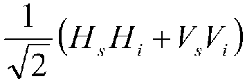

Zur Gewährleistung der Ununterscheidbarkeit der Pfade innerhalb der räumlichen Superposition ist eine Operation "quantum eraser" erforderlich. Diese Operation kann beispielsweise durch den zweiten Strahlteiler im MZI erfüllt werden. Die Ununterscheidbarkeit der Pfade ist aber auch vom Idler-Subsystem abhängig.To ensure the indistinguishability of the paths within the spatial superposition, a "quantum eraser" operation is required. This operation can be performed, for example, by the second beam splitter in the MZI. However, the indistinguishability of the paths also depends on the idler subsystem.
Im Idler-Subsystem ist nach dem Aufprägen der Phasendifferenz innerhalb der Träger-Superposition eine Operation "quantum eraser" QE erforderlich (HWP-22,5, Polarisator, Adsorption). Diese kann beispielsweise durch einen Polarisator realisiert werden. (Walborn[13])In the idler subsystem, after imposing the phase difference within the carrier superposition, a quantum eraser (QE) operation is required (HWP-22.5, polarizer, adsorption). This can be realized, for example, by a polarizer. (Walborn [13] )
Das Verfahren erlaubt auch die Beeinflussung der Interferenz im MZI des Signal-Subsystems durch Messung der Polarisation des Idler-Photons und des dadurch festgelegten Pfades des verschränkten Signal-Photons im MZI durch Drehung des Polarisators in eine geeignete Polarisationsebene, die die Pfadinformation offenbart. Dies unterbindet die Interferenz. Die Intensitäten sind bei 50:50 Strahlteilern dann in beiden Ausgangsmoden des MZI im Signal-Subsystem gleich.The method also allows for influencing the interference in the MZI of the signal subsystem by measuring the polarization of the idler photon and the resulting path of the entangled signal photon in the MZI by rotating the polarizer into a suitable polarization plane that reveals the path information. This eliminates the interference. The intensities are then the same in both beam splitters. Output modes of the MZI in the signal subsystem are the same.
Durch Messungen der Detektoren Det-1 und Det-2 kann lokal die Existenz von Interferenz und bei implementierter Korrelation zwischen der aufgeprägten Phasendifferenz im Idler-Subsystem und den Intensitätsmaxima der Ausgangsmoden des MZI im Signal-Subsystem auch der Zustand des Manipulationsmechanismus des Phasenlösungsraumes im Idler-Subsystem auf statistischer Ebene festgestellt werden.By measurements of the detectors Det-1 and Det-2, the existence of interference can be determined locally and, if a correlation is implemented between the imposed phase difference in the idler subsystem and the intensity maxima of the output modes of the MZI in the signal subsystem, also the state of the manipulation mechanism of the phase solution space in the idler subsystem can be determined at the statistical level.
Die Nicht-Lokalität von EPR-Effekten bei verschränkten Quanten ist gesicherter Stand der Wissenschaft und Technik. Die Darstellung des gemeinsamen Phasenzustandes eines verschränkten Paares Photonen mit nur einem Partner ist bekannt (Ma [6]; Lemos[2]). Die vorliegende Erfindung erlaubt bei verschränkten Photonen die lokale Messung einer nicht-lokalen Beeinflussung. Die Verwendung einer Koinzidenzmessung ist nicht erforderlich.The non-locality of EPR effects in entangled quanta is well established in science and technology. The representation of the common phase state of an entangled pair of photons with only one partner is known (Ma [6] ; Lemos [2] ). The present invention allows the local measurement of a non-local influence in entangled photons. The use of a coincidence measurement is not required.
Die Operatoren "quantum eraser" als jeweilige Abschlussoperation des jeweiligen Partners des verschränkten Photonenpaares in den beiden Subsystemen zur Aufrechterhaltung der räumlichen Superposition etablieren eine temporale Superposition der zeitlichen Abfolge:
- (QEs zeitlich vor QEi) + (QEs zeitlich nach QEi)
- und schaffen damit die Basis für einen EPR-Effekt und somit auch für einen "delayed choice"-Effekt.
- (QE s in time before QE i ) + (QE s in time after QE i )
- and thus create the basis for an EPR effect and thus also for a "delayed choice" effect.
Im Folgenden wird nicht nur über vierstellige Bezugszeichen, sondern zur Verbesserung der Lesbarkeit auch über Kurzbezeichnungen Bezug auf das Implementierungsbeispiel in
Alle optischen und elektronischen Maßnahmen zur Erhöhung der signifikanten Photonenrate im Detektor wie optische Linsen, Filter, Beschichtungen von optischen Elementen, wellenlängenabhängige Optimierung von optischen Elementen, Kompensatoren zum Ausgleichen der Pfadlängen im MZI und dem pMZA und dergleichen sind nicht explizit dargestellt.All optical and electronic measures to increase the significant photon rate in the detector such as optical lenses, filters, coatings of optical elements, wavelength-dependent optimization of optical elements, compensators to compensate the path lengths in the MZI and the pMZA and the like are not explicitly shown.
Das Verfahren benötigt eine Quelle verschränkter Photonen.The process requires a source of entangled photons.
Eine typische Quelle für Photonen ist ein kollinearer, monochromatischer Laser, wie in
Um die gewünschte Träger-Superposition zu generieren, wird der Pump-Strahl mittels eines HWP22,5̊ 1121 auf eine Superposition der Polarisation 
Zur Erzeugung verschränkter Photonen dient ein Paar BBO-Kristalle NL 1201, die um 90° zueinander gedreht sind. Die Orientierung der zusammengesetzten BBO-Kristalle ist so gewählt, dass durch den SPDC-Prozess ein 3°-Kegel verschränkter Photonen (signal-Photonen und idler-Photonen) mit identer Wellenlänge von 810 nm entsteht. Bei einem SPDC-Prozess Typ I mit den beschriebenen zusammengesetzten Kristallen und dem beschriebenen Pump-Strahl entstehen verschränkte Photonenpaare in der Träger-Superposition 
Die verschränkten Photonen werden in unterschiedliche Sub-Systeme, die Signal-Subsystem-Mode ISPKs> 1211 und die Idler-Subsystem-Mode ISPKi> 1212, gelenkt. Zur besseren Kontrollierbarkeit der Photonen und der zu durchlaufenden Pfade wird eine Quelle linear polarisierter Photonen in einem der Bell-Zustände, hier 
Die Photonen können in freier Übertragung oder in Lichtleitern (fiber) übertragen werden. Bei Verwendung von Lichtleitern sind Polarisations-Stabilisatoren erforderlich, wenn die Träger-Superposition für die Phasenmanipulation die Polarisation ist.The photons can be transmitted freely or via fiber optics. When using fiber optics, polarization stabilizers are required if the carrier superposition for phase manipulation is polarization.
Die beliebige und daher variable Länge des optischen Pfades von der Quelle der verschränkten Photonen NL 1201 zum Strahlteiler wird durch den Kreis mit der Beschriftung VD 1301 (VD=variable distance) zum Ausdruck gebracht.The arbitrary and therefore variable length of the optical path from the source of the entangled photons NL 1201 to the beam splitter is expressed by the circle labeled VD 1301 (VD=variable distance).
Für das Verfahren ist zumindest eine räumliche Superposition der Pfade als Teil des Gesamtsystems erforderlich. Diese räumliche Superposition wird durch ein Interferometer, in diesem Ausführungsbeispiel durch ein Mach-Zehnder-Interferometer MZI 1400, hergestellt. Da die lokale Messung im Signal-Subsystem vorgesehen ist, wird das Interferometer im Signal-Subsystem angeordnet. Da verschränkte Photonen den Phasenlösungsraum der Pfadintegrale gemeinsam definieren, reicht die Existenz einer räumlichen Superposition in einem der Subsysteme.The procedure requires at least a spatial superposition of the paths as part of the The entire system is required. This spatial superposition is achieved by an interferometer, in this embodiment, a Mach-
Durch Verwendung eines polarisierenden Strahlteilers PBSs 1401 im Interferometer im Signal-Subsystem im Implementierungsbeispiel ist die Pfadvorgabe für die Superposition der Polarisierung jeweils eindeutig: es entstehen die beiden Moden der räumlichen Superposition a 1411 und b 1412. Die Mode b wird durch einen feststehenden Spiegel M 1431, die Mode a durch einen verstellbaren Spiegel mMφMZI 1432 umgelenkt, sodass beide auf einen Strahlteiler BS 1402 treffen. Dieser ist ein 50:50 Strahlteiler und überlagert die beiden Moden der räumlichen Superposition a 1411 und b 1412. Da im Pfad der Mode b 1412 ein HWP45° 1421 (HWP=half waver plate) so angeordnet ist, dass die Polarisation der Photonen in diesem Arm des Interferometers auf die andere Polarisation geändert wird, sind die überlagerten Photonen im Durchgang durch den Strahlteiler ununterscheidbar und können daher interferieren.By using a polarizing
Der Strahlteiler BS 1402 erfüllt am Ende der räumlichen Superposition die Aufgabe der Operation "quantum eraser". Danach ist im Signal-Subsystem sichergestellt, dass der Pfadverlauf aus den Informationen des Signal-Subsystems nicht mehr nachvollziehbar ist.At the end of the spatial superposition, the
Entsprechend der gemeinsamen Phase und der daraus errechenbaren Wahrscheinlichkeitsverteilung wird das Signal-Photon entweder Richtung Detektor Det-2 1702 oder Detektor Det-1 1701 gelenkt.According to the common phase and the resulting probability distribution, the signal photon is directed either towards detector Det-2 1702 or detector Det-1 1701.
Zur Optimierung des MZI ist der Spiegel mMφMZI 1432 linear beweglich und als Phasenschieber angeordnet. Diese Art der Steuerung der Phase innerhalb eines MZI findet sich beispielsweise in Heuer[15]. Die Art des Aufbaues eines MZI findet sich beispielsweise auch in Cramer[16].To optimize the MZI, the
Die optische Strecke zwischen der Quelle der verschränkten Photonen und einem Pancharatnam-Berry-Phase-Shifter 1530 kann beliebig und daher variabel lang umgesetzt werden. Dies wird durch den Kreis mit der Beschriftung VD 1302 zum Ausdruck gebracht. Zur Umsetzung einer "delayed choice" Anordnung ist das Längenverhältnis 
Das Idler-Subsystem implementiert eine Vorrichtung zur Einbringung einer Phasendifferenz in die "Träger-Superposition", welche hier die Polarisation ist. Die Variante gemäß
Der Pancharatnam-Berry-Phase-Shifter 1530 besteht aus zwei quater wave plates QWP 1520, 1522, zwischen denen ein half wave plate HWP 1521 angeordnet ist. Auf diese Weise kann durch Rotation des HWP 1521, welches Teil des Pancharatnam-Berry-Phase-Shifters 1530 ist, die Phase der Träger-Superposition um einen Wert βm verändert werden, siehe Galvez[7].The Pancharatnam-
Der Polarisator POL45° 1621 hat die Aufgabe, die Polarisation im Idler-Subsystem ununterscheidbar zu machen und dadurch ebenfalls die Weg-Information im Idler-Subsystem zu "löschen". Dadurch wird explizit die Operation "quantum eraser" implementiert. Gemeinsam mit der Operation "quantum eraser" im Signal-Subsystem wird dadurch die räumliche Superposition aktiv gehalten, was die Messung von Interferenz im Signal-Subsystem erlaubt.The
Die Messung in Detektor Det-3 1703 ist für die Signal-Erkennung im Signal-Subsystem nicht erforderlich (statistisches Signal/Protokoll).The measurement in detector Det-3 1703 is not required for signal detection in the signal subsystem (statistical signal/protocol).
Die nichtlokale Beeinflussung des Phasenlösungsraumes des MZI durch das Aufprägen einer zusätzlichen Phasendifferenz im Idler-Subsystem kann an den beiden Ausgangsmoden des 50:50 Strahlteilers BS 1402 durch die Detektoren Det-1 und Det-2 als statistisches Protokoll gemessen werden. Diese Messung der "second order interference" ist bei richtig gewählten Phasen φMZI und βm bereits mit einem Detektor messbar.The nonlocal influence on the phase solution space of the MZI by imposing an additional phase difference in the idler subsystem can be measured as a statistical protocol at the two output modes of the 50:50
Die Ausführungsform gemäß
Vor dem pMZA 1500 befindet sich ein HWP 1525, das die Polarisation in die Ebene +45° (oder -45°) dreht. Statt eines HWP kann natürlich auch ein EOM (elektro-optischer Modulator) verwendet werden, um die Polarisationsebene entsprechend zu drehen. Durch das HWP 1525 entsteht im nachfolgenden pMZA 1500 eine Superposition der Pfade.A HWP 1525 is located upstream of the
Horizontal und vertikal polarisierte Photonen werden in jeweils einen Arm des pMZA 1500 durch den polarisierenden Strahlteiler PBSi1 1501 gelenkt. In einem Arm, mit Mode d 1512 bezeichnet, befindet sich ein fest stehender Spiegel M 1531, im anderen Arm, mit Mode c 1511 bezeichnet, befindet sich ein verstellbarer Spiegel mMβm 1532. Durch diese beiden Spiegel werden die Photonen in den beiden Armen auf den polarisierenden Strahlteiler PBSi2 1502 geworfen, wo sie wieder vereinigt werden.Horizontally and vertically polarized photons are directed into one arm each of the
Der linear bewegliche Spiegel mMβm 1532 realisiert einen Phasenschieber mit der Phase βm, sodass diesen Photonen eine zusätzliche Phase βm (in einer idealisierten Realisation gilt βm = π) aufgeprägt werden kann. Diese Phase ist durch das pMZA 1500 genau einer Polarisierung zugeordnet.The linearly movable mirror mMβ m 1532 implements a phase shifter with phase β m , allowing these photons to be imprinted with an additional phase β m (in an idealized realization, β m = π). This phase is assigned to exactly one polarization by the
Damit die Moden c 1511 und d 1512 in dem polarisierenden Strahlteiler PBSi2 1502 ohne Interferenz überlagert werden können, wird die jeweilige Polarisation durch das HWP 1521 (kann auch durch zwei HWP realisiert werden) getauscht. Dazu ist in beiden Moden ein HWP45° 1521 notwendig, um im Strahlteiler PBSi2 1502 die gewünschte Transmission/Reflektion zu gewährleisten (Jacqucs[14]).To ensure that the
Diese Vorrichtung ähnelt also einem Interferometer, da aber keine Interferenz messbar gemacht werden soll, ist es kein Interferometer im engeren Sinne. Diese Anordnung wird daher in der vorliegenden Beschreibung als polarisierender Mach-Zehnder-Aligner pMZA bezeichnet.This device is similar to an interferometer, but since it is not intended to measure interference, it is not an interferometer in the strict sense. This arrangement is therefore referred to in this description as a polarizing Mach-Zehnder aligner (pMZA).
Durch den Phasenschieber kann eine zusätzliche Phase, welche dann nur für diesen Teil der Superposition der Polarisation wirkt, eingebracht werden. Aus 

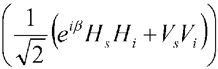
Ohne Beschränkung der Allgemeinheit kann man die Position des Spiegels mMβm 1532 so wählen, dass bei Interferenz im Signal-Subsystem das Maximum der Intensität bei Detektor Det-2 auftritt.Without loss of generality, the position of the mirror mMβ m 1532 can be chosen so that in case of interference in the signal subsystem the maximum intensity occurs at detector Det-2.
Ein weiterer Unterschied der Ausführungsform gemäß
Die Detektion von Interferenzen kann nur durch statistische Protokolle erreicht werden, da innerhalb der Interferometer eine Detektion eines einzelnen Quantums, z.B. im Detektor Det-1 1701, keine Aussagekraft hat (z. B. Dunkelzählraten der Detektoren). Die lokale Messung der Übereinstimmung von Detektionen durch Detektoren Det-1 1701 mit Det-2 1702 kann verwendet werden, um die Qualität der Messung zu verbessern.The detection of interference can only be achieved by statistical protocols, since within the interferometers a detection of a single quantum, e.g. in the detector Det-1 1701, has no significance (e.g. dark count rates of the detectors). The local measurement of the agreement of detections by detectors Det-1 1701 with Det-2 1702 can be used to improve the quality of the measurement.
Neben der Optimierung der Effizienz jeder Stufe ist die massive parallele Nutzung solcher Kommunikationskanäle eine gültige Methode zur Verbesserung der Baudraten um Größenordnungen von 2 bis 4 oder sogar mehr und ermöglicht eine zeiteffiziente Fehlerkorrektur.In addition to optimizing the efficiency of each stage, the massive parallel use of such communication channels is a valid method to improve baud rates by orders of magnitude of 2 to 4 or even more and enables time-efficient error correction.
Eine zusätzliche Verbesserung kann erreicht werden, indem solche Kommunikationskanäle auch in die entgegengesetzte Richtung implementiert werden, um die übertragenen Informationen zu bestätigen. In diesem Fall muss die relativistische Kausalität "kausale Kohärenz" respektiert werden.
- [1]
X. Y. Zou, L. J. Wang, and L. Mandel, "Induced coherence and indistinguishability in optical interference", Phys. Rev. Lett., vol. 67, no. 3, pp. 318-321, Jul. 1991, doi: 10.1103/PhysRevLett.67.318 - [2]
G. B. Lemos, V. Borish, G. D. Cole, S. Ramelow, R. Lapkiewicz, and A. Zeilinger, "Quantum imaging with undetected photons", Nature, vol. 512, p. 409, Aug. 2014 - [3]
A. Einstein, B. Podolsky, and N. Rosen, "Can Quantum-Mechanical Description of Physical Reality Be Considered Complete?", Phys. Rev., vol. 47, no. 10, pp. 777-780, May 1935, doi: 10.1103/PhysRev.47.777 - [4] "
The Feynman Lectures on Physics Vol. III Ch. 1: Quantum Behavior", https://www.feynmanlectures.caltech.edu/III 01.html#Ch1-S7 (accessed Sep. 19, 2020 - [5]
R. P. F. PH.D, R. P. Feynman, A. R. Hibbs, and A. R. Hibbs, "Quantum Mechanics and Path Integrals", McGraw-Hill, 1965 - [6]
X. Ma et al., "Quantum erasure with causally disconnected choice", Proc Natl Acad Sci USA, vol. 110, no. 4, pp. 1221-1226, Jan. 2013, doi: 10.1073/pnas.1213201110 - [7]
E. J. Galvez, M. Malik, and B. C. Melius, "Phase shifting of an interferometer using nonlocal quantum-state correlations", Phys. Rev. A, vol. 75, no. 2, p. 020302, Feb. 2007, doi: 10.1103/PhysRevA.75.020302 - [8]
G. Jaeger, M. A. Horne, and A. Shimony, "Complementarity of one-particle and two-particle interference", Phys. Rev. A, vol. 48, no. 2, pp. 1023-1027, Aug. 1993, doi: 10.1103/PhysRevA.48.1023 - [9]
X. Ma, J. Kofler, and A. Zeilinger, "Delayed-choice gedanken experiments and their realizations", Rev. Mod. Phys., vol. 88, no. 1, p. 015005, Mar. 2016, doi: 10.1103/RevModPhys.88.015005 - [10]
P. G. Kwiat, E. Waks, A. G. White, I. Appelbaum, and P. H. Eberhard, "Ultra-bright source of polarization-entangled photons," Phys. Rev. A, vol. 60, no. 2, pp. R773-R776, Aug. 1999, doi: 10.1103/PhysRevA.60.R773 - [11]
M. J. Pysher, E. J. Galvez, K. Misra, K. R. Wilson, B. C. Melius, and M. Malik, "Nonlocal labeling of paths in a single-photon interferometer," Phys. Rev. A, vol. 72, no. 5, p. 052327, Nov. 2005, doi: 10.1103/PhysRevA.72.052327 - [12]
P. Kwiat, "Observation of a nonclassical Berry's phase for the photon", ResearchGate https://www.researchgate.net/publication/13245896 Observation of a no nclassical Berry's phase for the photon , March 1991 (accessed Sep. 06, 2020 - [13]
S. P. Walborn, M. O. T. Cunha, S. Padua, and C. H. Monken, "A double-slit quantum eraser," Phys. Rev. A, vol. 65, no. 3, p. 033818, Feb. 2002, doi: 10.1103/PhysRevA.65.033818 - [14]
V. Jacques et al., "Experimental realization of Wheeler's delayed-choice Gedanken Experiment" in 2007 European Conference on Lasers and Electro-Optics and the International Quantum Electronics Conference, Jun. 2007, pp. 1-1, doi: 10.1109/CLEOE-IQEC.2007.4386903 - [15]
A. Heuer, R. Menzel, and P. W. Milonni, "Induced Coherence, Vacuum Fields, and Complementarity in Biphoton Generation", Phys. Rev. Lett., vol. 114, no. 5, p. 053601, Feb. 2015, doi: 10.1103/PhysRevLett.114.053601 - [16]
J. G. Cramer and N. Herbert, "An Inquiry into the Possibility of Nonlocal Quantum Communication," arXiv:1409.5098 [quant-ph], Sep. 2014, Accessed: Feb. 19, 2019. [Online Available: http://arxiv.org/abs/1409.5098
- [1]
XY Zou, LJ Wang, and L. Mandel, “Induced coherence and indistinguishability in optical interference,” Phys. Rev. Lett., vol. 67, no. 3, pp. 318-321, Jul. 1991, doi: 10.1103/PhysRevLett.67.318 - [2]
GB Lemos, V. Borish, GD Cole, S. Ramelow, R. Lapkiewicz, and A. Zeilinger, "Quantum imaging with undetected photons," Nature, vol. 512, p. 409, Aug 2014 - [3]
A. Einstein, B. Podolsky, and N. Rosen, "Can Quantum-Mechanical Description of Physical Reality Be Considered Complete?", Phys. Rev., vol. 47, no. 10, pp. 777-780, May 1935, doi: 10.1103/PhysRev.47.777 - [4] "
The Feynman Lectures on Physics Vol - [5]
RPF PH.D, RP Feynman, AR Hibbs, and AR Hibbs, "Quantum Mechanics and Path Integrals", McGraw-Hill, 1965 - [6]
X. Ma et al., “Quantum erasure with causally disconnected choice,” Proc Natl Acad Sci USA, vol. 110, no. 4, pp. 1221-1226, Jan. 2013, doi: 10.1073/pnas.1213201110 - [7]
EJ Galvez, M. Malik, and BC Melius, "Phase shifting of an interferometer using nonlocal quantum-state correlations," Phys. Rev. A, vol. 75, no. 2, p. 020302, Feb. 2007, doi: 10.1103/PhysRevA.75.020302 - [8]
G. Jaeger, MA Horne, and A. Shimony, “Complementarity of one-particle and two-particle interference,” Phys. Rev. A, vol. 48, no. 2, pp. 1023-1027, Aug. 1993, doi: 10.1103/PhysRevA.48.1023 - [9]
X. Ma, J. Kofler, and A. Zeilinger, "Delayed-choice thought experiments and their realizations," Rev. Mod. Phys., vol. 88, no. 1, p. 015005, Mar. 2016, doi: 10.1103/RevModPhys.88.015005 - [10]
PG Kwiat, E. Waks, AG White, I. Appelbaum, and PH Eberhard, "Ultra-bright source of polarization-entangled photons," Phys. Rev. A, vol. 60, no. 2, pp. R773-R776, Aug. 1999, doi: 10.1103/PhysRevA.60.R773 - [11]
MJ Pysher, EJ Galvez, K. Misra, KR Wilson, BC Melius, and M. Malik, "Nonlocal labeling of paths in a single-photon interferometer," Phys. Rev. A, vol. 72, no. 5, p. 052327, Nov. 2005, doi: 10.1103/PhysRevA.72.052327 - [12]
P. Kwiat, "Observation of a nonclassical Berry's phase for the photon", ResearchGate https://www.researchgate.net/publication/13245896 Observation of a nonclassical Berry's phase for the photon, March 1991 (accessed Sep. 06, 2020 - [13]
SP Walborn, MOT Cunha, S. Padua, and CH Monken, "A double-slit quantum eraser," Phys. Rev. A, vol. 65, no. 3, p. 033818, Feb. 2002, doi: 10.1103/PhysRevA.65.033818 - [14]
V. Jacques et al., "Experimental realization of Wheeler's delayed-choice thought experiment" in 2007 European Conference on Lasers and Electro-Optics and the International Quantum Electronics Conference, Jun. 2007, pp. 1-1, doi: 10.1109/CLEOE-IQEC.2007.4386903 - [15]
A. Heuer, R. Menzel, and PW Milonni, “Induced Coherence, Vacuum Fields, and Complementarity in Biphoton Generation,” Phys. Rev. Lett., vol. 114, no. 5, p. 053601, Feb. 2015, doi: 10.1103/PhysRevLett.114.053601 - [16]
JG Cramer and N. Herbert, "An Inquiry into the Possibility of Nonlocal Quantum Communication," arXiv:1409.5098 [quant-ph], Sep. 2014, Accessed: Feb. 19, 2019. [Online Available: http://arxiv.org/abs/1409.5098
Claims (4)
- Method for transmitting information by means of entangled quanta capable of interference, namely by means of idler quanta entangled with signal quanta, characterized in that an arrangement is used whicha) provides for at least one spatial superposition within the system space "paths";b) provides for a temporal superposition of quantum operations (quantum eraser), which eliminates the unambiguous assignment of information about the paths of spatial superposition within the relativistic causality space;c) provides for a superposition (carrier superposition) of a measurable and controllable attribute of the entangled quanta, e.g. B. of their polarization;d) provides a method for manipulating this attribute with the phase solution space of the path integrals of the system of entangled quanta, namely in the idler subsystem;e) in the signal subsystem, two exit modes are provided for measuring the interference, and in the idler subsystem only the spatial superposition of exit modes without interference measurement is provided for,and in changing the attribute in the idler subsystem using the manipulation method and measuring the changing interference in the signal subsystem.
- Arrangement for carrying out the method according to claim 1, characterized in that it contains:a) a photon source, in particular a laser (1101);b) a source of entangled photons, in particular a non-linear crystal (1201), which generates entangled photons, namely signal photons and idler photons, from the photons of the laser (1101);c) a beam guidance system that guides the signal photons into a signal subsystem and the idler photons into an idler subsystem;d) in the signal subsystem:i) an interferometer (1400);ii) at least one detector (1701, 1702) at the output of the interferometer (1400);e) in the idler subsystem:iii) a Mach-Zehnder aligner (1500) with two polarizing beam splitters (1501, 1502), wherein a half-wave plate (1521) is arranged in both arms and a mirror (1532) is displaceable; or a Pancharatnam-Berry phase shifter; andiv) after the Mach-Zehnder aligner (1500) or the Pancharatnam-Berry phase shifter, a polarizer (1621) to delete the path information in the idler subsystem.
- Arrangement according to claim 2, characterized in that the interferometer (1400) mentioned in i) is a Mach-Zehnder interferometer.
- Arrangement according to claim 3, characterized in that the first beam splitter (1401) of the Mach-Zehnder interferometer (1400) is a polarizing beam splitter and that an optical element rotating the polarization plane by 90°, in particular a half-wave plate (1421), is arranged in one of the two interferometer arms.
Applications Claiming Priority (2)
| Application Number | Priority Date | Filing Date | Title |
|---|---|---|---|
| AT505032021 | 2021-06-21 | ||
| PCT/AT2022/060209 WO2022266685A1 (en) | 2021-06-21 | 2022-06-21 | Method for transmitting information by means of entangled quanta and assembly for carrying out the method |
Publications (3)
| Publication Number | Publication Date |
|---|---|
| EP4360010A1 EP4360010A1 (en) | 2024-05-01 |
| EP4360010C0 EP4360010C0 (en) | 2025-05-14 |
| EP4360010B1 true EP4360010B1 (en) | 2025-05-14 |
Family
ID=82482621
Family Applications (1)
| Application Number | Title | Priority Date | Filing Date |
|---|---|---|---|
| EP22740276.5A Active EP4360010B1 (en) | 2021-06-21 | 2022-06-21 | Method for information transmission via entangled quanta and arrangement for carrying out the method |
Country Status (3)
| Country | Link |
|---|---|
| US (1) | US20250158722A1 (en) |
| EP (1) | EP4360010B1 (en) |
| WO (1) | WO2022266685A1 (en) |
Family Cites Families (4)
| Publication number | Priority date | Publication date | Assignee | Title |
|---|---|---|---|---|
| US7302187B1 (en) * | 2004-12-08 | 2007-11-27 | United States Of America As Represented By The Secretary Of The Navy | Minimum transmitted photon quantum optical communications system |
| US7639953B2 (en) * | 2006-07-27 | 2009-12-29 | Hewlett-Packard Development Company, L.P. | Compact systems for generating polarization-entangled photons |
| US8149591B2 (en) * | 2009-02-20 | 2012-04-03 | Creston Electronics Inc. | Wall box dimmer |
| US10935379B2 (en) * | 2016-11-29 | 2021-03-02 | The Trustees Of The Stevens Institute Of Technology | Method and apparatus for quantum measurement via mode matched photon conversion |
-
2022
- 2022-06-21 WO PCT/AT2022/060209 patent/WO2022266685A1/en not_active Ceased
- 2022-06-21 EP EP22740276.5A patent/EP4360010B1/en active Active
- 2022-06-21 US US18/571,378 patent/US20250158722A1/en active Pending
Also Published As
| Publication number | Publication date |
|---|---|
| EP4360010C0 (en) | 2025-05-14 |
| EP4360010A1 (en) | 2024-05-01 |
| US20250158722A1 (en) | 2025-05-15 |
| WO2022266685A1 (en) | 2022-12-29 |
Similar Documents
| Publication | Publication Date | Title |
|---|---|---|
| Cogan et al. | Deterministic generation of indistinguishable photons in a cluster state | |
| Liu et al. | Distributed quantum phase estimation with entangled photons | |
| DE69432482T2 (en) | KEY DISTRIBUTION METHOD USING QUANTUM CRYPTOGRAPHY | |
| DE112008002429B4 (en) | Integrated hybrid source of polarization entangled photons | |
| Delteil et al. | Generation of heralded entanglement between distant hole spins | |
| Basso Basset et al. | Quantum teleportation with imperfect quantum dots | |
| EP1055308B1 (en) | Method and device for producing a choice of either single photons or pairs of photons in an optical channel | |
| Specht et al. | Phase shaping of single-photon wave packets | |
| WO1999066641A1 (en) | Method for generating a random number on a quantum-mechanics basis and random generator | |
| DE2140440A1 (en) | Light modulation system | |
| DE69404130T2 (en) | METHOD AND DEVICE FOR DETECTING OPTICALLY CODED SIGNALS | |
| DE10196893T5 (en) | Spatial light modulator and light pulse waveform control | |
| Kawase et al. | Observing quantum correlation of photons in Laguerre-Gauss modes using the Gouy phase | |
| DE102018113054A1 (en) | Method for illuminating samples in microscopic imaging methods | |
| Lemos et al. | Experimental observation of quantum chaos in a beam of light | |
| Emam et al. | Periodic dark and bright optical soliton dynamics in atomic medium governed by control fields of milnor polynomial and super-gaussian beam | |
| DE60209561T2 (en) | ACTIVE OPTICAL SYSTEM FOR PHASE SHIFTING OF DESIRED AREAS OF AN INITIAL OPTICAL WAVE FRONT | |
| Liu et al. | Relation between wave-particle duality and quantum uncertainty | |
| Hamilton et al. | Quantum walk with a four-dimensional coin | |
| WO2022266685A1 (en) | Method for transmitting information by means of entangled quanta and assembly for carrying out the method | |
| EP4327419B1 (en) | Superposition device and optical system | |
| EP1269679B1 (en) | Method for changing the polarisation of at least one photon of the photons which are radiated from a photon pair source to form various partial beam paths and a method for producing individual photons or photon pairs in an optical channel | |
| Takeuchi | Photonic quantum information: science and technology | |
| Kwiat | Nonclassical effects from spontaneous parametric down-conversion: adventures in quantum wonderland | |
| DE102006029035B4 (en) | Apparatus and method for the production and detection in amplitude, phase and polarization of shaped laser pulses |
Legal Events
| Date | Code | Title | Description |
|---|---|---|---|
| STAA | Information on the status of an ep patent application or granted ep patent |
Free format text: STATUS: UNKNOWN |
|
| STAA | Information on the status of an ep patent application or granted ep patent |
Free format text: STATUS: THE INTERNATIONAL PUBLICATION HAS BEEN MADE |
|
| PUAI | Public reference made under article 153(3) epc to a published international application that has entered the european phase |
Free format text: ORIGINAL CODE: 0009012 |
|
| STAA | Information on the status of an ep patent application or granted ep patent |
Free format text: STATUS: REQUEST FOR EXAMINATION WAS MADE |
|
| 17P | Request for examination filed |
Effective date: 20231221 |
|
| AK | Designated contracting states |
Kind code of ref document: A1 Designated state(s): AL AT BE BG CH CY CZ DE DK EE ES FI FR GB GR HR HU IE IS IT LI LT LU LV MC MK MT NL NO PL PT RO RS SE SI SK SM TR |
|
| DAV | Request for validation of the european patent (deleted) | ||
| DAX | Request for extension of the european patent (deleted) | ||
| REG | Reference to a national code |
Ref country code: DE Ref legal event code: R079 Free format text: PREVIOUS MAIN CLASS: G06N0010000000 Ipc: G02F0001010000 Ref country code: DE Ref legal event code: R079 Ref document number: 502022003968 Country of ref document: DE Free format text: PREVIOUS MAIN CLASS: G06N0010000000 Ipc: G02F0001010000 |
|
| GRAP | Despatch of communication of intention to grant a patent |
Free format text: ORIGINAL CODE: EPIDOSNIGR1 |
|
| STAA | Information on the status of an ep patent application or granted ep patent |
Free format text: STATUS: GRANT OF PATENT IS INTENDED |
|
| INTG | Intention to grant announced |
Effective date: 20250124 |
|
| RIC1 | Information provided on ipc code assigned before grant |
Ipc: H04B 10/70 20130101ALI20250117BHEP Ipc: G06N 10/40 20220101ALI20250117BHEP Ipc: G06N 10/20 20220101ALI20250117BHEP Ipc: G02F 1/21 20060101ALI20250117BHEP Ipc: G02F 1/01 20060101AFI20250117BHEP |
|
| GRAS | Grant fee paid |
Free format text: ORIGINAL CODE: EPIDOSNIGR3 |
|
| GRAA | (expected) grant |
Free format text: ORIGINAL CODE: 0009210 |
|
| STAA | Information on the status of an ep patent application or granted ep patent |
Free format text: STATUS: THE PATENT HAS BEEN GRANTED |
|
| AK | Designated contracting states |
Kind code of ref document: B1 Designated state(s): AL AT BE BG CH CY CZ DE DK EE ES FI FR GB GR HR HU IE IS IT LI LT LU LV MC MK MT NL NO PL PT RO RS SE SI SK SM TR |
|
| REG | Reference to a national code |
Ref country code: GB Ref legal event code: FG4D Free format text: NOT ENGLISH |
|
| REG | Reference to a national code |
Ref country code: CH Ref legal event code: EP |
|
| REG | Reference to a national code |
Ref country code: IE Ref legal event code: FG4D Free format text: LANGUAGE OF EP DOCUMENT: GERMAN |
|
| REG | Reference to a national code |
Ref country code: DE Ref legal event code: R096 Ref document number: 502022003968 Country of ref document: DE |
|
| U01 | Request for unitary effect filed |
Effective date: 20250604 |
|
| U07 | Unitary effect registered |
Designated state(s): AT BE BG DE DK EE FI FR IT LT LU LV MT NL PT RO SE SI Effective date: 20250612 |
|
| U20 | Renewal fee for the european patent with unitary effect paid |
Year of fee payment: 4 Effective date: 20250616 |
|
| PGFP | Annual fee paid to national office [announced via postgrant information from national office to epo] |
Ref country code: AT Payment date: 20250721 Year of fee payment: 4 |
|
| PG25 | Lapsed in a contracting state [announced via postgrant information from national office to epo] |
Ref country code: ES Free format text: LAPSE BECAUSE OF FAILURE TO SUBMIT A TRANSLATION OF THE DESCRIPTION OR TO PAY THE FEE WITHIN THE PRESCRIBED TIME-LIMIT Effective date: 20250514 |
|
| PG25 | Lapsed in a contracting state [announced via postgrant information from national office to epo] |
Ref country code: NO Free format text: LAPSE BECAUSE OF FAILURE TO SUBMIT A TRANSLATION OF THE DESCRIPTION OR TO PAY THE FEE WITHIN THE PRESCRIBED TIME-LIMIT Effective date: 20250814 Ref country code: GR Free format text: LAPSE BECAUSE OF FAILURE TO SUBMIT A TRANSLATION OF THE DESCRIPTION OR TO PAY THE FEE WITHIN THE PRESCRIBED TIME-LIMIT Effective date: 20250815 |
|
| PG25 | Lapsed in a contracting state [announced via postgrant information from national office to epo] |
Ref country code: PL Free format text: LAPSE BECAUSE OF FAILURE TO SUBMIT A TRANSLATION OF THE DESCRIPTION OR TO PAY THE FEE WITHIN THE PRESCRIBED TIME-LIMIT Effective date: 20250514 |
|
| PG25 | Lapsed in a contracting state [announced via postgrant information from national office to epo] |
Ref country code: HR Free format text: LAPSE BECAUSE OF FAILURE TO SUBMIT A TRANSLATION OF THE DESCRIPTION OR TO PAY THE FEE WITHIN THE PRESCRIBED TIME-LIMIT Effective date: 20250514 |
|
| PGFP | Annual fee paid to national office [announced via postgrant information from national office to epo] |
Ref country code: CH Payment date: 20250701 Year of fee payment: 4 |
|
| PG25 | Lapsed in a contracting state [announced via postgrant information from national office to epo] |
Ref country code: RS Free format text: LAPSE BECAUSE OF FAILURE TO SUBMIT A TRANSLATION OF THE DESCRIPTION OR TO PAY THE FEE WITHIN THE PRESCRIBED TIME-LIMIT Effective date: 20250814 |
|
| PG25 | Lapsed in a contracting state [announced via postgrant information from national office to epo] |
Ref country code: IS Free format text: LAPSE BECAUSE OF FAILURE TO SUBMIT A TRANSLATION OF THE DESCRIPTION OR TO PAY THE FEE WITHIN THE PRESCRIBED TIME-LIMIT Effective date: 20250914 |
|
| PG25 | Lapsed in a contracting state [announced via postgrant information from national office to epo] |
Ref country code: SM Free format text: LAPSE BECAUSE OF FAILURE TO SUBMIT A TRANSLATION OF THE DESCRIPTION OR TO PAY THE FEE WITHIN THE PRESCRIBED TIME-LIMIT Effective date: 20250514 |
|
| PG25 | Lapsed in a contracting state [announced via postgrant information from national office to epo] |
Ref country code: CZ Free format text: LAPSE BECAUSE OF FAILURE TO SUBMIT A TRANSLATION OF THE DESCRIPTION OR TO PAY THE FEE WITHIN THE PRESCRIBED TIME-LIMIT Effective date: 20250514 |
|
| PG25 | Lapsed in a contracting state [announced via postgrant information from national office to epo] |
Ref country code: SK Free format text: LAPSE BECAUSE OF FAILURE TO SUBMIT A TRANSLATION OF THE DESCRIPTION OR TO PAY THE FEE WITHIN THE PRESCRIBED TIME-LIMIT Effective date: 20250514 |
|
| PG25 | Lapsed in a contracting state [announced via postgrant information from national office to epo] |
Ref country code: MC Free format text: LAPSE BECAUSE OF FAILURE TO SUBMIT A TRANSLATION OF THE DESCRIPTION OR TO PAY THE FEE WITHIN THE PRESCRIBED TIME-LIMIT Effective date: 20250514 |
|
| PLBE | No opposition filed within time limit |
Free format text: ORIGINAL CODE: 0009261 |
|
| STAA | Information on the status of an ep patent application or granted ep patent |
Free format text: STATUS: NO OPPOSITION FILED WITHIN TIME LIMIT |
|
| REG | Reference to a national code |
Ref country code: CH Ref legal event code: L10 Free format text: ST27 STATUS EVENT CODE: U-0-0-L10-L00 (AS PROVIDED BY THE NATIONAL OFFICE) Effective date: 20260325 |
|
| PG25 | Lapsed in a contracting state [announced via postgrant information from national office to epo] |
Ref country code: IE Free format text: LAPSE BECAUSE OF NON-PAYMENT OF DUE FEES Effective date: 20250621 |
|
| 26N | No opposition filed |
Effective date: 20260217 |
|
| U20 | Renewal fee for the european patent with unitary effect paid |
Year of fee payment: 5 Effective date: 20260423 |
|
| REG | Reference to a national code |
Ref country code: CH Ref legal event code: U11 Free format text: ST27 STATUS EVENT CODE: U-0-0-U10-U11 (AS PROVIDED BY THE NATIONAL OFFICE) Effective date: 20260701 |
|
| PGFP | Annual fee paid to national office [announced via postgrant information from national office to epo] |
Ref country code: GB Payment date: 20260424 Year of fee payment: 5 |
|
| PG25 | Lapsed in a contracting state [announced via postgrant information from national office to epo] |
Ref country code: CY Free format text: LAPSE BECAUSE OF FAILURE TO SUBMIT A TRANSLATION OF THE DESCRIPTION OR TO PAY THE FEE WITHIN THE PRESCRIBED TIME-LIMIT Effective date: 20250514 |