EP4359936B1 - Zeiteffiziente implementierung einer cache-ersatzrichtlinie - Google Patents
Zeiteffiziente implementierung einer cache-ersatzrichtlinie Download PDFInfo
- Publication number
- EP4359936B1 EP4359936B1 EP22786241.4A EP22786241A EP4359936B1 EP 4359936 B1 EP4359936 B1 EP 4359936B1 EP 22786241 A EP22786241 A EP 22786241A EP 4359936 B1 EP4359936 B1 EP 4359936B1
- Authority
- EP
- European Patent Office
- Prior art keywords
- lru
- cache
- nodes
- stage
- eligible
- Prior art date
- Legal status (The legal status is an assumption and is not a legal conclusion. Google has not performed a legal analysis and makes no representation as to the accuracy of the status listed.)
- Active
Links
Images





Classifications
-
- G—PHYSICS
- G06—COMPUTING OR CALCULATING; COUNTING
- G06F—ELECTRIC DIGITAL DATA PROCESSING
- G06F12/00—Accessing, addressing or allocating within memory systems or architectures
- G06F12/02—Addressing or allocation; Relocation
- G06F12/08—Addressing or allocation; Relocation in hierarchically structured memory systems, e.g. virtual memory systems
- G06F12/12—Replacement control
- G06F12/121—Replacement control using replacement algorithms
- G06F12/123—Replacement control using replacement algorithms with age lists, e.g. queue, most recently used [MRU] list or least recently used [LRU] list
-
- G—PHYSICS
- G06—COMPUTING OR CALCULATING; COUNTING
- G06F—ELECTRIC DIGITAL DATA PROCESSING
- G06F12/00—Accessing, addressing or allocating within memory systems or architectures
- G06F12/02—Addressing or allocation; Relocation
- G06F12/08—Addressing or allocation; Relocation in hierarchically structured memory systems, e.g. virtual memory systems
- G06F12/0802—Addressing of a memory level in which the access to the desired data or data block requires associative addressing means, e.g. caches
- G06F12/0864—Addressing of a memory level in which the access to the desired data or data block requires associative addressing means, e.g. caches using pseudo-associative means, e.g. set-associative or hashing
-
- G—PHYSICS
- G06—COMPUTING OR CALCULATING; COUNTING
- G06F—ELECTRIC DIGITAL DATA PROCESSING
- G06F12/00—Accessing, addressing or allocating within memory systems or architectures
- G06F12/02—Addressing or allocation; Relocation
- G06F12/08—Addressing or allocation; Relocation in hierarchically structured memory systems, e.g. virtual memory systems
- G06F12/12—Replacement control
- G06F12/121—Replacement control using replacement algorithms
- G06F12/126—Replacement control using replacement algorithms with special data handling, e.g. priority of data or instructions, handling errors or pinning
-
- G—PHYSICS
- G06—COMPUTING OR CALCULATING; COUNTING
- G06F—ELECTRIC DIGITAL DATA PROCESSING
- G06F12/00—Accessing, addressing or allocating within memory systems or architectures
- G06F12/02—Addressing or allocation; Relocation
- G06F12/08—Addressing or allocation; Relocation in hierarchically structured memory systems, e.g. virtual memory systems
- G06F12/12—Replacement control
- G06F12/121—Replacement control using replacement algorithms
- G06F12/128—Replacement control using replacement algorithms adapted to multidimensional cache systems, e.g. set-associative, multicache, multiset or multilevel
Definitions
- This specification relates to systems having integrated circuit devices.
- a cache is a device that stores data retrieved from memory or data to be written to memory for one or more different hardware devices in a system.
- the hardware devices can be different components integrated into a system on a chip (SOC).
- SOC system on a chip
- client devices Some caches service memory requests for multiple different client devices integrated into a single system.
- Caches can be used to reduce power consumption by reducing overall requests to the main memory.
- power can further be saved by placing the main memory as well as data paths to the main memory in a low-power state. Therefore, cache usage is correlated with overall power consumption, and increasing cache usage results in a decrease in overall power consumption. Therefore, devices that rely on battery power, e.g., mobile computing devices, can extend their battery life by increasing cache usage for the integrated client devices.
- a cache placement policy determines how a memory block is placed in the cache.
- a least recently used (LRU) replacement policy can be used.
- LRU replacement policy In conventional LRU replacement implementations, a system fits all the cache replacement operations in the same clock cycle for a transaction. However, because the execution time for most of the operations in the LRU replacement policy increases with the number of cache lines in a set of the cache, it can be challenging to fit all the operations for the transaction into a single clock cycle for a set-associative cache with high associativity.
- US 2020/0371932 A1 describes a first cache storage, a second cache storage, wherein the second cache storage includes a first portion operable to store a first set of data evicted from the first cache storage and a second portion, a cache controller coupled to the first cache storage and the second cache storage and operable to receive a write operation, determine that the write operation produces a miss in the first cache storage, and in response to the miss in the first cache storage, provide write miss information associated with the write operation to the second cache storage for storing in the second portion.
- US 2020/301840 A1 describes a method which determines to generate a prefetch request, obtains a confidence value for target data associated with the prefetch request, writes the target data into a set of the n-way set associative cache memory, modifies an n-position array of the cache memory, such that a particular one of n array positions identifies one of the n ways, wherein the particular one of the n LRU array positions is determined by the confidence value.
- This specification describes a cache system including multiple sets of cache lines and replacement logic configured to implement a two-stage least recently used (LRU) replacement policy.
- LRU least recently used
- a cache system in one particular aspect of the specification, includes multiple sets with each set having multiple respective ways, and replacement logic configured to implement a two-stage least recently used (LRU) replacement computation.
- the two-stage LRU replacement computation causes the cache to perform: a first stage during which the cache computes an LRU way for a set, and a second stage during which the cache updates an LRU data structure with information of a transaction accessed way.
- the cache is configured to perform the two-stage LRU replacement computation in consecutive clock cycles.
- the cache is configured to implement an LRU replacement policy using the computed LRU way.
- the replacement logic comprises a plurality of nodes storing respective way values for each set, and wherein performing the second stage comprises shifting the way values stored between the nodes for the set.
- the cache system to perform the second stage, is configured to update each node for a set with data the node already stores or data shifted from another node.
- the cache system when performing the first stage for a current transaction, in response to a hazard condition resulted from the second stage of a previous transaction being performed on a same particular set, the cache system performs hazard resolution for the current transaction.
- performing the hazard resolution for the current transaction includes: in response to determining that all of the respective ways in the particular set are eligible for replacement, determining the LRU way for the current transaction based on the LRU data structure after the LRU data structure has been updated for the previous transaction.
- the replacement logic is configured to, in response to determining that not all of the respective ways in the particular set are eligible for replacement: determining hazard-resolved eligible nodes from the plurality of nodes; selecting an eligible node from the hazard-resolved eligible nodes; and determining the LRU way using the way value stored in the selected eligible node.
- the replacement logic is configured to start determining the hazard-resolved eligible nodes from the plurality of nodes before the second stage of the previous transaction has been completed.
- determining the hazard-resolved eligible nodes from the plurality of nodes includes: generating un-resolved node data that identifies eligible nodes from the plurality of nodes based on eligible ways and the LRU data structure before the LRU data structure been updated by the second stage of the previous transaction; and shifting the un-resolved node data using shift information generated during the second stage of the previous transaction to generate hazard-resolved node data that identifies the hazard-resolved eligible nodes.
- a method for performing LRU replacement computation is provided. The method is performed by the cache system described above and includes the operations described above.
- the cache system improves the time efficiencies for performing multiple cache transactions.
- the system can start the hazard resolution process for the current transaction before the LRU update of the previous transaction has been finished, to minimize the time impact of hazard resolution.
- the increased timing efficiency can help implement advanced LRU replacement policy for set-associative caches with high associativity numbers.
- a cache placement policy determines how a memory block is placed in the cache. This specification focuses on the set-associative cache placement policy, where the cache is divided into multiple sets and each set includes multiple cache lines.
- FIG. 1 shows a cache system 100.
- the cache system 100 may be a part of a processing system, such as a system on a chip (SOC) communicatively coupled to memory devices.
- the cache system 100 is a set-associative cache and includes multiple sets 110. Each set 110 includes multiple respective cache lines 114.
- a cache line also known as a way, is the unit of data transfer between the cache and another memory device, e.g., the main memory of the processing system. All cache lines in the set have a fixed size, e.g., 64 bytes. A processor will read or write an entire cache line when any location in the 64-byte region is read or written.
- the cache system 100 further includes a cache transaction controller 120 that manages cache transactions of the cache system 100.
- a cache transaction refers to a process of accessing the cache system with a request for a specific memory block.
- An example cache transaction process will the described with reference to FIG. 2 .
- the cache transaction controller 120 maps the requested memory block to a specific set 110 using the index bits derived from the address of the memory block.
- the cache transaction controller 120 then performs a tag check to determine whether the requested memory block is already placed in one of the cache lines 110. The tag check is performed based on the tag data 130 that stores the tags of all the cache lines 114 of the memory device.
- the cache transaction controller 120 compares the tag bits of the address of the memory block with the tags of the cache lines 114 in the mapped set 110.
- the tag check returns a "cache hit” if the memory block tag matches any of the cache lines in the mapped set. Otherwise, the tag check returns a "cache miss".
- the cache transaction controller 120 requests the memory block from another memory device, such as from the main memory of the processing system or from the next-level cache of the processing system, and places the memory block in a selected cache line 114 of the mapped set 110. If all the cache lines 114 in the mapped set 110 have already been allocated (i.e., have been previously placed with respective memory blocks), the cache transaction controller 120 uses the new data read from the external memory device to replace the block stored in a cache line identified through a replacement policy.
- the system 100 uses the cache replacement logic 125 to implement a least recently used (LRU) replacement policy that selects the least recently used cache line (out of K-ways) for replacement.
- LRU least recently used
- This process requires keeping track of the recency of each cache line 114 with respect to the usage of all the other cache lines in a particular set 110.
- the system 100 maintains the LRU data 140 that specifies the recency information for each cache line 114 in each set 110 of the system 100.
- the cache replacement logic 125 implements the LRU replacement computation in two stages. During the first stage, the cache system 100 determines the least recently used cache line (termed as the LRU way in this application) based at least on the current LRU data 140. The LRU way is selected for replacement. During the second stage, the cache system 100 updates the LRU data 140 based on the information of the transaction accessed way, so the LRU data 140 is up to date for the next transaction.
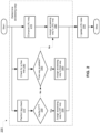
- FIG. 2 illustrates an example process 200 for performing a cache transaction.
- the process 200 will be described as being performed by a cache system, such as the cache system 100 of FIG. 1 .
- the system Before performing the process 200, the system has determined the set for the cache transaction.
- the output of the process 200 specifies a particular cache line (termed as the "accessing way” in this specification) in the set for accessing the memory block specified in the cache transaction request.
- the system After receiving the cache transaction request specifying the memory block, the system performs a tag check in step 210. In particular, the system compares the tag bits associated with the address of the memory block with the tags of the cache lines in the set.
- the system determines whether the tag check results in a cache HIT or MISS in step 220. That is, if the tag bits associated with the address of the memory block match the tag of one of the cache lines in the set, the system determines that the tag check result is a cache HIT. For convenience, the cache line that has the tag matching the memory block tag is termed as "HIT way”. If the tag bits associated with the address of the memory block do not match any of the tags of the cache lines in the set, the system determines that the tag check result is a MISS.
- the system determines that the tag check result is a cache HIT, the system uses the HIT way for the transaction, and thus assigns the accessing way to the HIT way in step 230.
- the system determines that the tag check result is a cache MISS, this means that the data in the specified memory block has not been loaded into any of the cache lines in the set, and the system needs to request the data from a next level in the memory hierarchy, and load the data into a selected cache line in the set.
- the system checks for a cache line in the set that has not been occupied in step 240. For convenience, an unoccupied cache line is termed the "free way". If the system determines that a free way is available in step 250, the system uses the free way for performing the transaction for the cache MISS scenario. That is, the system assigns the accessing way to the free way in step 260.
- step 250 If the system determines that a free way is not available in step 250, this means that all the cache lines in the set have been occupied, and the system needs to identify a cache line for replacement through the replacement policy, and place the data in the cache line identified for replacement.
- the system computes the LRU way in step 270.
- the system assigns the accessing way to the LRU way in step 280.
- the system updates the LRU data in step 290.
- the LRU data tracks the recency of the cache lines in the set, i.e., specifies how recently a particular cache line has been accessed for a transaction compared to other cache lines in the set. The update process will be described in more detail with references to FIGs. 4A-6 .
- a system fits all the operations shown in FIG. 2 in the same clock cycle for a transaction.
- 0 ( ⁇ operation >) denotes the timing depth for completing the ⁇ operation>
- C is a constant time delay for operations such as selecting one of the HIT way/free way/compute LRU way branches shown in FIG. 2 .
- each of the three terms O(determine hitway), O(select freeway), and O(compute LRU way) increases when the total number of cache lines in the set increases. That is, the time for determining the accessing way increases with increased cache associativity.
- the cache associativity is significant (e.g., when the total number of cache lines in the set exceeds a threshold), it can be challenging to fit all the operations for the transaction into a single clock cycle.
- the system described in this specification performs the LRU replacement using a 2-stage scheme. That is, the system implements the two-stage LRU replacement policy in consecutive clock cycles.
- the system determines the accessing way.
- the system updates the LRU data.
- T 2 O Update LRU data
- the system can generally improve the time efficiencies for performing the cache transaction. For example, after the system has determined the accessing way in the first stage for a particular transaction, instead of waiting for the LRU data update to finish for the particular transaction in the second stage, the system can start the first stage for the next cache transaction, i.e. start determining the accessing way for the next cache transaction while performing the second stage for the particular cache transaction. Thus, second stage of a current transaction and the first stage of the next transaction can be performed in parallel. This scheme generally shortens the total time required for performing the multiple cache transactions.
- FIG. 3 illustrates clock cycles for performing cache operations for 3 cache transactions.
- the first transaction (txt 1) is performed on a first set (Set A) in the cache.
- the second transaction (txt 2) is performed on a second set (Set B) in the cache.
- the third transaction (txt 3) is also performed on the second set (Set B)
- the system performs the first stage of the first transaction.
- the system performs the second stage of the first transaction and the first stage of the second transaction.
- the system performs the second stage of the second transaction and the first stage of the third transaction.
- a hazard refers to a problem with the instruction pipeline when the next instruction cannot correctly execute in the following clock cycle, e.g., due to instructions that exhibit data dependence upon modified data in different stages of a pipeline. Because the first and the second transactions are performed on different sets, there is no data dependence between the two transactions, and hazards do not occur.
- the first stage of the third transaction may need to use the LRU data of the set to determine the accessing way (e.g., for computing LRU way), while the LRU data of the same set is being updated in the second stage of the second transaction. This results in a hazard. Therefore, in order to correctly compute the LRU way for the third transaction, the hazard needs to be resolved. Example processes and implementations for resolving the hazard will be described with reference to FIG. 5 and FIG. 7 .
- FIG. 4A shows an example data structure 400 for storing the LRU data.
- the data structure includes a sequence of K nodes having one-to-one correspondence to the K cache lines in the set.
- Each node 410 stores a way value 412 identifying the corresponding cache line.
- the respective node index k of a node 410 specifies the recency of the cache line identified by the way value 412 of the node 410.
- the cache line identified by the way value stored in the 0 th node is the least recently accessed cache line in the set
- the cache line identified by the way value stored in the ( k - 1) th node is the most recently accessed cache line in the set.
- the system updates the LRU data by shifting the way values 412 stored in the sequence of nodes 410.
- FIG. 4B illustrates an example process for updating the LRU data stored in a data structure, e.g., in the sequence of nodes shown in FIG. 4A .
- the top row of nodes store way values before the LRU data update.
- the bottom row of nodes store way values after the LRU data update.
- Both rows of nodes are arranged in decreasing order of recency from left to right. That is, the left-most node of each row stores the way value of the most recently used (MRU) cache line, and the right-most node of each row stores the way value of the least recently used (LRU) cache line.
- MRU most recently used
- LRU least recently used
- the accessing way for the transaction is identified by the way value "2" stored in the 4th node from the left of the top row.
- the system updates the LRU data to reflect the change in the recency by moving the way value "2" to the MRU node and shifting the way values stored in the 1st through 3rd nodes from the left to the right by one node, resulting in the way values shown in the bottom row.
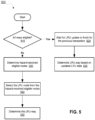
- FIG. 5 shows an example process 500 for performing hazard resolution in LRU computation.
- the process 500 will be described as being performed by a cache system, such as the cache system 100 of FIG. 1 .
- step 510 of the hazard resolution process 500 the system determines if all the cache lines in the set are eligible for replacement. This step is needed because in some scenarios, the cache system can be accessed by multiple client devices.
- a client device is a device that issues read requests and write requests to the cache system to access data of the cache system.
- each client device may only use a subset of cache lines in the current set for replacement. Thus, for the current transaction associated with a particular client device, only a subset of cache lines are eligible for replacement, and the system can compute the LRU way only from the eligible cache lines.
- step 520 the system can simply perform step 520 to wait for the LRU update to finish, before performing step 525 to determine the LRU way for the current transaction based on the updated LRU data (that has been updated for the previous transaction). For example, in step 525, the system can simply determine the LRU way that is specified by the way value 412 stored in the LRU node (node 0) of the LRU data 400 as shown in FIG. 4A , where all the LRU data nodes 410 have been updated for the previous transaction. Since the LRU way is selected based on the up-to-date LRU data with regard to the previous transaction, the selected LRU way is hazard resolved.
- the system determines that not all the cache lines in the set are eligible for replacement, i.e., only a subset of cache lines in the set are eligible for replacement for the current transaction, the system needs to identify the eligible subset of cache lines before determining the LRU way from the eligible cache lines. Since the recency information of the cache lines can be stored in the respective LRU data nodes (e.g., as shown in FIG. 4A ), the system can determine the eligible cache lines by determining the eligible set of LRU data nodes, and using the respective stored way values 412 stored in the eligible LRU data nodes to identify the eligible cache lines.
- an eligible LRU data nodes refers to an LRU data node that stores a way value identifying an eligible cache line.
- a hazard-resolved eligible node refers to an LRU data node that stores an up-to-date way value that identifies an eligible cache line.
- the up-to-date way value refers to the way value that is consistent with the updated LRU data from the previous transaction.
- the system starts the step of determining the hazard-resolved eligible nodes for the current transaction before the LRU data update is completed for the previous transaction.
- This can be achieved by directly using the node shift information of updating the LRU data in the previous transaction.
- the node shift information specifies, for each node of the LRU data for the current set, whether the node is shifted (or to be shifted) by the LRU data update process for the previous transaction.
- the system selects the LRU node from the hazard-resolved eligible nodes in step 540.
- the selected LRU node is the least recently used node among the set of hazard-resolved eligible nodes.
- the system determines the LRU way using the way value stored in the selected LRU node.
- FIG. 6 shows an example hardware implementation 600 of an LRU cache replacement policy applied to the LRU data (i.e., respective way values for the cache lines in the set) stored in a sequence of nodes 640.
- the sequence of K nodes 610 are arranged according to the recency (with decreasing recency from left to right) of the cache lines identified by the respective way values stored in the nodes. That is, in the example shown in FIG. 6 , the leftmost node, i.e., node (K - 1), stores the way value of the MRU cache line while the rightmost node, i.e., node 0, stores the way value of the LRU cache line.
- the circuit 600 includes a plurality of comparators 640, a plurality of OR gates 650, and a plurality of multiplexers 660.
- the circuit receives as an input the accessing way 605 determined by the first stage of the cache transaction, and compares the accessing way 605 with each of the way values stored in the nodes 610 using a respective comparator 640.
- the output of the comparator 650 is connected to a first input to a respective logic OR gate 650.
- the output of the k th comparator 640 is connected to the first input of the k th OR gate, and the second input of the k th OR gate is connected to the output of the ( k - 1) th OR gate.
- the output of the k th comparator 640 is connected to the first input of the k th OR gate, and the second input of the k th OR gate is connected to the output of the ( k - 1) th comparator. That is, the OR gate performs OR operation to the comparison results for the current node (node Zc) and all preceding nodes (nodes 0, 1, ... k - 1). If one of the nodes 0, 1, ... k stores the way value that matches the accessing way 605, the k th OR gate outputs "1". If none of the nodes 0, 1, ..., k stores the way value that matches the accessing way 605, the k th OR gate outputs "0".
- the output of the k th OR gate is connected to the control input of a respective multiplexer 660 (MUX Zc).
- k 1, 2, ..., (K - 1).
- the control input of the rightmost multiplexer (MUX 0) is connected to the comparison result for node 0.
- the data inputs of the leftmost multiplexer (MUX ( k - 1)) are connected to node ( K - 1) and the accessing way input, respectively.
- the multiplexers 660 output the updated LRU data 630, i.e., the way values that have been shifted according to the control inputs of the multiplexers 660.
- the circuit 600 further outputs the control inputs of the multiplexers 660 as the shift flag signal 620.
- the shift flag signal 620 includes a respective flag value for each particular LRU data node 610 for indicating whether a shift operation has been performed (or is to be performed) to the way value stored in the particular LRU data node 610. As described with reference to FIG. 7 , the system can use the shift flag signal 620 for performing hazard resolution between two transactions.
- FIG. 7 shows an example hardware implementation 700 for cache hazard resolution between the current cache transaction and previous cache transaction.
- the circuit 700 receives several input signals, including: (1) the eligible ways 730 identifying the cache lines that are eligible for replacement in the set for the current transaction; (2) the accessing way 705 for the previous transaction; (3) the shift flag 720 outputted by the previous transaction and specifies shift information for the LRU data nodes for the LRU data update in the previous transaction; (4) the updated LRU data 740 that specifies the way values that have been updated by the previous transaction; (5) the un-updated LRU data 710 that specifies the way values that have not been updated by the previous transaction; and (6) the hazard flag 760 that indicates whether to perform hazard resolution between the previous transaction and the current transaction.
- the circuit 700 outputs the LRU way 770 computed for the current transaction.
- the input signals 705, 720, and 730 can be available for the current transaction before the LRU data update process has been completed for the previous transaction.
- the data processing using these input signals can be started for the current transaction before the LRU data update process has been completed for the previous transaction.
- the circuit 700 includes a plurality of K ⁇ 1 multiplexers 702, including MUX 0, MUX 1, ..., MUX K.
- Each K ⁇ 1 multiplexer 702 receives the eligible ways 730 as the inputs.
- the eligible ways 730 can be encoded into "1" or "0" flags in a K-length vector for the K cache lines in the set, where a "1" flag indicates that the corresponding way is eligible for replacement and a "0" flag indicates that the corresponding way is not eligible for replacement.
- Each of MUX 0, ... , MUX (K - 1) also obtains the way values from the respective LRU data nodes 710 as the control input. Note that way values received by the multiplexers MUX 0, ...
- MUX (K - 1) are outdated way values, i.e., way values that have not been updated by the second stage (T2) of the pervious transaction.
- the multiplexer MUX K receives the accessing way 705 as the second input.
- the outputs of the multiplexer 702 specify the un-resolved eligible LRU data nodes that have not been hazard-resolved. That is, the output of a multiplexer 702 specifies whether a corresponding node stores an outdated way value identifying one of the eligible cache lines.
- the outdated way value refers to the way value that has not been updated by the LRU data update process of the previous transaction.
- the circuit 700 includes a plurality of multiplexers 704 that receive the shift flag signal 720 as control signal.
- the data inputs of each multiplexer 704 are connected to the outputs of two adjacent K ⁇ 1 multiplexer 702.
- the multiplexers 704 performs data shifting on the un-resolved eligible LRU data nodes based on the shift flag 720 when there is a hazard.
- the hazard signal 760 indicates that the two transactions are performed to the same set i.e., there is hazard.
- the multiplexers 704 Since the shift flag 720 has been outputted by the previous transaction and specifies shift information for the LRU data nodes for the previous transaction, the multiplexers 704 performs the same data shifting on the un-resolved eligible LRU data nodes as being performed by the previous transaction on the LRU data nodes. Thus, the outputs of the multiplexers 704 specify the hazard-resolved LRU data nodes.
- the circuit 700 includes a fix priority arbiter 790 that performs a fixed priority arbitration among the hazard-resolved eligible nodes and select the LRU node 780, i.e., the least recently used node as indicated by the node indexes, among the hazard-resolved eligible nodes.
- the circuit 700 can use another K ⁇ 1 multiplexer 708 receives the selected LRU node 780 as the control signal to select the LRU way 770 from the updated LRU data 740 or the un-updated LRU data 710, depending on the hazard signal 760.
- the circuit 700 is configured to perform hazard resolution on the eligible LRU data nodes for the current transaction at least in part in parallel with the LRU data update process of the previous transaction.
- the described cache system can overcome certain limitations of conventional LRU replacement implementations, and improve the time efficiencies for performing multiple cache transactions.
- Embodiments of the subject matter and the functional operations described in this specification can be implemented in digital electronic circuitry, in tangibly-embodied computer software or firmware, in computer hardware, including the structures disclosed in this specification, or in combinations of one or more of them.
- Embodiments of the subject matter described in this specification can be implemented as one or more computer programs, i.e., one or more modules of computer program instructions encoded on a tangible non-transitory storage medium for execution by, or to control the operation of, data processing apparatus.
- the computer storage medium can be a machine-readable storage device, a machine-readable storage substrate, a random or serial access memory device, or a combination of one or more of them.
- the program instructions can be encoded on an artificially-generated propagated signal, e.g., a machine-generated electrical, optical, or electromagnetic signal, that is generated to encode information for transmission to suitable receiver apparatus for execution by a data processing apparatus.
- Embodiments of the subject matter described in this specification can be implemented as one or more computer programs, i.e., one or more modules of computer program instructions encoded on a tangible non transitory storage medium for execution by, or to control the operation of, data processing apparatus.
- the computer storage medium can be a machine-readable storage device, a machine-readable storage substrate, a random or serial access memory device, or a combination of one or more of them.
- the program instructions can be encoded on an artificially generated propagated signal, e.g., a machine-generated electrical, optical, or electromagnetic signal, that is generated to encode information for transmission to suitable receiver apparatus for execution by a data processing apparatus.
- data processing apparatus refers to data processing hardware and encompasses all kinds of apparatus, devices, and machines for processing data, including by way of example a programmable processor, a computer, or multiple processors or computers.
- the apparatus can also be, or further include, special purpose logic circuitry, e.g., an FPGA (field programmable gate array) or an ASIC (application specific integrated circuit).
- the apparatus can optionally include, in addition to hardware, code that creates an execution environment for computer programs, e.g., code that constitutes processor firmware, a protocol stack, a database management system, an operating system, or a combination of one or more of them.
- a computer program which may also be referred to or described as a program, software, a software application, an app, a module, a software module, a script, or code, can be written in any form of programming language, including compiled or interpreted languages, or declarative or procedural languages; and it can be deployed in any form, including as a stand alone program or as a module, component, subroutine, or other unit suitable for use in a computing environment.
- a program may, but need not, correspond to a file in a file system.
- a program can be stored in a portion of a file that holds other programs or data, e.g., one or more scripts stored in a markup language document, in a single file dedicated to the program in question, or in multiple coordinated files, e.g., files that store one or more modules, sub programs, or portions of code.
- a computer program can be deployed to be executed on one computer or on multiple computers that are located at one site or distributed across multiple sites and interconnected by a data communication network.
- the processes and logic flows described in this specification can be performed by one or more programmable computers executing one or more computer programs to perform functions by operating on input data and generating output.
- the processes and logic flows can also be performed by special purpose logic circuitry, e.g., an FPGA or an ASIC, or by a combination of special purpose logic circuitry and one or more programmed computers.
- Computers suitable for the execution of a computer program can be based on general or special purpose microprocessors or both, or any other kind of central processing unit.
- a central processing unit will receive instructions and data from a read only memory or a random access memory or both.
- the essential elements of a computer are a central processing unit for performing or executing instructions and one or more memory devices for storing instructions and data.
- the central processing unit and the memory can be supplemented by, or incorporated in, special purpose logic circuitry.
- a computer will also include, or be operatively coupled to receive data from or transfer data to, or both, one or more mass storage devices for storing data, e.g., magnetic, magneto optical disks, or optical disks. However, a computer need not have such devices.
- a computer can be embedded in another device, e.g., a mobile telephone, a personal digital assistant (PDA), a mobile audio or video player, a game console, a Global Positioning System (GPS) receiver, or a portable storage device, e.g., a universal serial bus (USB) flash drive, to name just a few.
- PDA personal digital assistant
- GPS Global Positioning System
- USB universal serial bus
- Computer readable media suitable for storing computer program instructions and data include all forms of non volatile memory, media and memory devices, including by way of example semiconductor memory devices, e.g., EPROM, EEPROM, and flash memory devices; magnetic disks, e.g., internal hard disks or removable disks; magneto optical disks; and CD ROM and DVD-ROM disks.
- semiconductor memory devices e.g., EPROM, EEPROM, and flash memory devices
- magnetic disks e.g., internal hard disks or removable disks
- magneto optical disks e.g., CD ROM and DVD-ROM disks.
Landscapes
- Engineering & Computer Science (AREA)
- Theoretical Computer Science (AREA)
- Physics & Mathematics (AREA)
- General Engineering & Computer Science (AREA)
- General Physics & Mathematics (AREA)
- Memory System Of A Hierarchy Structure (AREA)
Claims (15)
- Cache (100), umfassend:mehrere Sätze (110), wobei jeder Satz mehrere jeweilige Wege (114) aufweist; undErsetzungslogik (125), die dazu konfiguriert ist, eine zweistufige LRU-Ersetzungsberechnung (least recently used, LRU) zu implementieren, wobei die zweistufige LRU-Ersetzungsberechnung den Cache veranlasst, Vorgänge durchzuführen, die Folgendes umfassen:eine erste Phase, während der der Cache einen LRU-Weg für einen Satz berechnet, undeine zweite Phase, während der der Cache eine LRU-Datenstruktur (140) mit Informationen über eine Transaktion, auf die zugegriffen wurde, aktualisiert;dadurch gekennzeichnet, dass Durchführen der ersten Phase für eine aktuelle Transaktion Folgendes umfasst:
als Reaktion auf eine Gefahrenbedingung, die sich aus der zweiten Phase einer vorherigen Transaktion ergibt, die mit demselben bestimmten Satz durchgeführt wurde, Durchführen der Gefahrenauflösung (500) für die aktuelle Transaktion. - Cache nach Anspruch 1, wobei der Cache dazu konfiguriert ist, die zweistufige LRU-Ersetzungsberechnung in aufeinanderfolgenden Taktzyklen durchzuführen.
- Cache nach Anspruch 1, wobei der Cache dazu konfiguriert ist, eine LRU-Ersetzungsrichtlinie unter Verwendung des berechneten LRU-Weges zu implementieren.
- Cache nach Anspruch 1, wobei die Ersetzungslogik (125) eine Vielzahl von Knoten umfasst, die jeweilige Wegwerte für jeden Satz (110) speichern, und wobei das Durchführen der zweiten Phase das Verschieben der zwischen den Knoten gespeicherten Wegwerte für den Satz umfasst.
- Cache nach Anspruch 4, wobei das Durchführen der zweiten Phase Aktualisieren jedes Knotens für einen Satz (110) mit Daten, die der Knoten bereits speichert, oder mit von einem anderen Knoten verschobenen Daten umfasst.
- Cache nach Anspruch 1, wobei das Durchführen der Gefahrenauflösung für die aktuelle Transaktion Folgendes umfasst:
als Reaktion auf Bestimmen, dass alle jeweiligen Wege (114) in dem bestimmten Satz (110) für eine Ersetzung in Frage kommen, Bestimmen des LRU-Weges für die aktuelle Transaktion basierend auf der LRU-Datenstruktur (140), nachdem die LRU-Datenstruktur für die vorherige Transaktion aktualisiert worden ist. - Cache nach Anspruch 1, wobei die Ersetzungslogik (125) zu Folgendem konfiguriert ist, als Reaktion auf das Bestimmen, dass nicht alle der jeweiligen Wege (110) in dem bestimmten Satz für eine Ersetzung in Frage kommen:Bestimmen von gefährdungsaufgelösten geeigneten Knoten aus der Vielzahl von Knoten;Auswählen eines geeigneten Knotens aus den gefährdungsaufgelösten geeigneten Knoten; undBestimmen des LRU-Weges unter Verwendung des Wegwertes, der in dem ausgewählten geeigneten Knoten gespeichert ist.
- Cache nach Anspruch 7, wobei die Ersetzungslogik (125) dazu konfiguriert ist, mit dem Bestimmen der gefährdungsaufgelösten in Frage kommenden Knoten aus der Vielzahl von Knoten zu beginnen, bevor die zweite Phase der vorherigen Transaktion erfüllt ist, und optional, wobei das Bestimmen der gefährdungsaufgelösten in Frage kommenden Knoten aus der Vielzahl von Knoten Folgendes umfasst:Erzeugen von nicht aufgelösten Knotendaten, die geeignete Knoten aus der Vielzahl von Knoten basierend auf geeigneten Wegen und der LRU-Datenstruktur identifizieren, bevor die LRU-Datenstruktur durch die zweite Phase der vorherigen Transaktion aktualisiert wurde; undVerschieben der nicht aufgelösten Knotendaten unter Verwendung der während der zweiten Phase der vorherigen Transaktion erzeugten Verschiebungsinformationen, um gefahraufgelöste Knotendaten zu erzeugen, die die gefahraufgelösten in Frage kommenden Knoten identifizieren.
- Verfahren zum Durchführen einer LRU-Ersatzberechnung für einen Cache, der mehrere Sätze (110) beinhaltet, wobei jeder Satz mehrere jeweilige Wege (114) aufweist:Berechnen (270) eines LRU-Weges für einen Satz während einer ersten Phase; undAktualisierung (290) einer LRU-Datenstruktur mit Informationen über eine Transaktion, auf die in einer zweiten Phase zugegriffen wurde;wobei das Durchführen der ersten Phase für eine aktuelle Transaktion Folgendes umfasst:als Reaktion auf eine Gefahrenbedingung, die sich aus der zweiten Phase einer vorherigen Transaktion ergibt, die mit demselben bestimmten Satz durchgeführt wurde, Durchführen der Gefahrenauflösung für die aktuelle Transaktion.
- Verfahren nach Anspruch 9, wobei die erste Phase und die zweite Phase in aufeinanderfolgenden Taktzyklen durchgeführt werden.
- Verfahren nach Anspruch 9, wobei der Cache dazu konfiguriert ist, eine LRU-Ersetzungspolitik unter Verwendung des berechneten LRU-Weges zu implementieren.
- Verfahren nach Anspruch 9, wobei:
das Verfahren ferner Folgendes umfasst: Speichern jeweiliger Wegwerte für jeden Satz (110) in einer Vielzahl von Knoten; und wobei das Durchführen der zweiten Phase das Verschieben der zwischen den Knoten für den Satz gespeicherten Wegwerte umfasst und optional, wobei das Durchführen der zweiten Phase das Aktualisieren jedes Knotens für einen Satz mit Daten, die der Knoten bereits speichert, oder mit von einem anderen Knoten verschobenen Daten umfasst. - Verfahren nach Anspruch 9, wobei das Durchführen der Gefahrenauflösung für die aktuelle Transaktion Folgendes umfasst:
als Reaktion auf Bestimmen, dass alle jeweiligen Wege (114) in dem bestimmten Satz für eine Ersetzung in Frage kommen, Bestimmen des LRU-Weges für die aktuelle Transaktion basierend auf der LRU-Datenstruktur (140), nachdem die LRU-Datenstruktur für die vorherige Transaktion aktualisiert worden ist. - Verfahren nach Anspruch 9, wobei das Durchführen der Gefahrenauflösung für die aktuelle Transaktion Folgendes umfasst, als Reaktion auf das Bestimmen, dass nicht alle der jeweiligen Wege (114) in dem bestimmten Satz für einen Austausch in Frage kommen:Bestimmen von gefährdungsaufgelösten geeigneten Knoten aus der Vielzahl von Knoten;Auswählen eines geeigneten Knotens aus den gefährdungsaufgelösten geeigneten Knoten; undBestimmen des LRU-Weges unter Verwendung des Wegwertes, der in dem ausgewählten geeigneten Knoten gespeichert ist.
- Verfahren nach Anspruch 14, wobei das Bestimmen von gefährdungsaufgelösten geeigneten Knoten Folgendes umfasst: Beginnen des Bestimmens der gefährdungsaufgelösten in Frage kommenden Knoten aus der Vielzahl von Knoten, bevor die zweite Phase der vorherigen Transaktion erfüllt ist, und optional, wobei
das Bestimmen der gefährdungsaufgelösten geeigneten Knoten Folgendes umfasst:Erzeugen von nicht aufgelösten Knotendaten, die geeignete Knoten aus der Vielzahl von Knoten basierend auf geeigneten Wegen (114) und der LRU-Datenstruktur (140) identifizieren, bevor die LRU-Datenstruktur durch die zweite Phase der vorherigen Transaktion aktualisiert wurde; undVerschieben der nicht aufgelösten Knotendaten unter Verwendung der während der zweiten Phase der vorherigen Transaktion erzeugten Verschiebungsinformationen, um gefahraufgelöste Knotendaten zu erzeugen, die die gefahraufgelösten in Frage kommenden Knoten identifizieren.
Applications Claiming Priority (1)
| Application Number | Priority Date | Filing Date | Title |
|---|---|---|---|
| PCT/US2022/076285 WO2024058801A1 (en) | 2022-09-12 | 2022-09-12 | Time-efficient implementation of cache replacement policy |
Publications (2)
| Publication Number | Publication Date |
|---|---|
| EP4359936A1 EP4359936A1 (de) | 2024-05-01 |
| EP4359936B1 true EP4359936B1 (de) | 2024-11-06 |
Family
ID=83598532
Family Applications (1)
| Application Number | Title | Priority Date | Filing Date |
|---|---|---|---|
| EP22786241.4A Active EP4359936B1 (de) | 2022-09-12 | 2022-09-12 | Zeiteffiziente implementierung einer cache-ersatzrichtlinie |
Country Status (7)
| Country | Link |
|---|---|
| US (1) | US20260086952A1 (de) |
| EP (1) | EP4359936B1 (de) |
| JP (1) | JP2025529409A (de) |
| KR (1) | KR20250053933A (de) |
| CN (1) | CN119895409A (de) |
| TW (1) | TWI867623B (de) |
| WO (1) | WO2024058801A1 (de) |
Family Cites Families (20)
| Publication number | Priority date | Publication date | Assignee | Title |
|---|---|---|---|---|
| US7856633B1 (en) * | 2000-03-24 | 2010-12-21 | Intel Corporation | LRU cache replacement for a partitioned set associative cache |
| US6823427B1 (en) * | 2001-05-16 | 2004-11-23 | Advanced Micro Devices, Inc. | Sectored least-recently-used cache replacement |
| US6857048B2 (en) * | 2002-01-17 | 2005-02-15 | Intel Corporation | Pseudo least-recently-used (PLRU) replacement method for a multi-node snoop filter |
| US7039760B2 (en) * | 2003-04-28 | 2006-05-02 | International Business Machines Corporation | Programming means for dynamic specifications of cache management preferences |
| US9513959B2 (en) * | 2007-11-21 | 2016-12-06 | Arm Limited | Contention management for a hardware transactional memory |
| US7962695B2 (en) * | 2007-12-04 | 2011-06-14 | International Business Machines Corporation | Method and system for integrating SRAM and DRAM architecture in set associative cache |
| US8171220B2 (en) * | 2009-04-24 | 2012-05-01 | International Business Machines Corporation | Cache architecture with distributed state bits |
| US10019381B2 (en) * | 2012-05-01 | 2018-07-10 | Nvidia Corporation | Cache control to reduce transaction roll back |
| US9734059B2 (en) * | 2012-11-21 | 2017-08-15 | Advanced Micro Devices, Inc. | Methods and apparatus for data cache way prediction based on classification as stack data |
| US9176879B2 (en) * | 2013-07-19 | 2015-11-03 | Apple Inc. | Least recently used mechanism for cache line eviction from a cache memory |
| US9367348B2 (en) * | 2013-08-15 | 2016-06-14 | Globalfoundries Inc. | Protecting the footprint of memory transactions from victimization |
| US20150193355A1 (en) * | 2014-01-07 | 2015-07-09 | Samsung Electronics Co., Ltd. | Partitioned cache replacement algorithm |
| US9715461B2 (en) * | 2014-03-03 | 2017-07-25 | Kabushiki Kaisha Toshiba | Cache memory control circuit and processor |
| WO2016042353A1 (en) * | 2014-09-18 | 2016-03-24 | Via Alliance Semiconductor Co., Ltd. | Cache management request fusing |
| US9652400B2 (en) * | 2014-12-14 | 2017-05-16 | Via Alliance Semiconductor Co., Ltd. | Fully associative cache memory budgeted by memory access type |
| EP3066571B1 (de) * | 2014-12-14 | 2018-06-13 | VIA Alliance Semiconductor Co., Ltd. | Speicherzugangsbasierte budgetierung eines cache-speichers |
| US9898411B2 (en) * | 2014-12-14 | 2018-02-20 | Via Alliance Semiconductor Co., Ltd. | Cache memory budgeted by chunks based on memory access type |
| US10789175B2 (en) * | 2017-06-01 | 2020-09-29 | Mellanox Technologies Ltd. | Caching policy in a multicore system on a chip (SOC) |
| US20200301840A1 (en) * | 2019-03-20 | 2020-09-24 | Shanghai Zhaoxin Semiconductor Co., Ltd. | Prefetch apparatus and method using confidence metric for processor cache |
| US12147353B2 (en) * | 2019-05-24 | 2024-11-19 | Texas Instruments Incorporated | Methods and apparatus for read-modify-write support in multi-banked data RAM cache for bank arbitration |
-
2022
- 2022-09-12 EP EP22786241.4A patent/EP4359936B1/de active Active
- 2022-09-12 KR KR1020257009802A patent/KR20250053933A/ko active Pending
- 2022-09-12 WO PCT/US2022/076285 patent/WO2024058801A1/en not_active Ceased
- 2022-09-12 US US19/111,200 patent/US20260086952A1/en active Pending
- 2022-09-12 JP JP2025514809A patent/JP2025529409A/ja active Pending
- 2022-09-12 CN CN202280100527.4A patent/CN119895409A/zh active Pending
-
2023
- 2023-07-18 TW TW112126708A patent/TWI867623B/zh active
Also Published As
| Publication number | Publication date |
|---|---|
| CN119895409A (zh) | 2025-04-25 |
| TWI867623B (zh) | 2024-12-21 |
| US20260086952A1 (en) | 2026-03-26 |
| TW202411849A (zh) | 2024-03-16 |
| JP2025529409A (ja) | 2025-09-04 |
| KR20250053933A (ko) | 2025-04-22 |
| WO2024058801A1 (en) | 2024-03-21 |
| EP4359936A1 (de) | 2024-05-01 |
Similar Documents
| Publication | Publication Date | Title |
|---|---|---|
| US11726917B2 (en) | Method and apparatus for a page-local delta-based prefetcher | |
| US10908945B2 (en) | Handling memory requests | |
| KR102538139B1 (ko) | 공간적 메모리 스트리밍 신뢰 메커니즘 | |
| US9026739B2 (en) | Multimode prefetcher | |
| US7707397B2 (en) | Variable group associativity branch target address cache delivering multiple target addresses per cache line | |
| US10671535B2 (en) | Stride prefetching across memory pages | |
| KR102329308B1 (ko) | 캐시 교체 정책 방법들 및 시스템들 | |
| US7873820B2 (en) | Processor utilizing a loop buffer to reduce power consumption | |
| US20200285592A1 (en) | Multilevel cache eviction management | |
| US9489203B2 (en) | Pre-fetching instructions using predicted branch target addresses | |
| US7953953B2 (en) | Method and apparatus for reducing page replacement time in system using demand paging technique | |
| CN103544054A (zh) | 用于在事务性存储器系统中实现强原子性的方法、装置和系统 | |
| US20140143499A1 (en) | Methods and apparatus for data cache way prediction based on classification as stack data | |
| US11163573B2 (en) | Hierarchical metadata predictor with periodic updates | |
| US20040073752A1 (en) | Method and apparatus for pre-fetching data during program execution | |
| US10853075B2 (en) | Controlling accesses to a branch prediction unit for sequences of fetch groups | |
| CN120029933A (zh) | 数据请求处理方法、装置、电子设备、存储介质和程序产品 | |
| CN119473162A (zh) | 缓存管理方法及装置、缓存、电子装置以及存储介质 | |
| US9223714B2 (en) | Instruction boundary prediction for variable length instruction set | |
| CN109478164A (zh) | 用于存储用于高速缓存条目传输的高速缓存位置信息的系统和方法 | |
| US20080189495A1 (en) | Method for reestablishing hotness of pages | |
| EP4359936B1 (de) | Zeiteffiziente implementierung einer cache-ersatzrichtlinie | |
| CN110045921B (zh) | 用于数据处理的装置和访问存储电路的方法 | |
| US20250363062A1 (en) | Low-latency cache | |
| CN117743210A (zh) | 选择性控制流预测器插入 |
Legal Events
| Date | Code | Title | Description |
|---|---|---|---|
| STAA | Information on the status of an ep patent application or granted ep patent |
Free format text: STATUS: UNKNOWN |
|
| STAA | Information on the status of an ep patent application or granted ep patent |
Free format text: STATUS: EXAMINATION IS IN PROGRESS |
|
| PUAI | Public reference made under article 153(3) epc to a published international application that has entered the european phase |
Free format text: ORIGINAL CODE: 0009012 |
|
| 17P | Request for examination filed |
Effective date: 20230911 |
|
| AK | Designated contracting states |
Kind code of ref document: A1 Designated state(s): AL AT BE BG CH CY CZ DE DK EE ES FI FR GB GR HR HU IE IS IT LI LT LU LV MC MK MT NL NO PL PT RO RS SE SI SK SM TR |
|
| GRAP | Despatch of communication of intention to grant a patent |
Free format text: ORIGINAL CODE: EPIDOSNIGR1 |
|
| STAA | Information on the status of an ep patent application or granted ep patent |
Free format text: STATUS: GRANT OF PATENT IS INTENDED |
|
| RIC1 | Information provided on ipc code assigned before grant |
Ipc: G06F 12/128 20160101ALI20240415BHEP Ipc: G06F 12/126 20160101ALI20240415BHEP Ipc: G06F 12/0864 20160101ALI20240415BHEP Ipc: G06F 12/123 20160101AFI20240415BHEP |
|
| DAV | Request for validation of the european patent (deleted) | ||
| DAX | Request for extension of the european patent (deleted) | ||
| INTG | Intention to grant announced |
Effective date: 20240515 |
|
| GRAS | Grant fee paid |
Free format text: ORIGINAL CODE: EPIDOSNIGR3 |
|
| GRAA | (expected) grant |
Free format text: ORIGINAL CODE: 0009210 |
|
| STAA | Information on the status of an ep patent application or granted ep patent |
Free format text: STATUS: THE PATENT HAS BEEN GRANTED |
|
| P01 | Opt-out of the competence of the unified patent court (upc) registered |
Free format text: CASE NUMBER: APP_49743/2024 Effective date: 20240902 |
|
| AK | Designated contracting states |
Kind code of ref document: B1 Designated state(s): AL AT BE BG CH CY CZ DE DK EE ES FI FR GB GR HR HU IE IS IT LI LT LU LV MC MK MT NL NO PL PT RO RS SE SI SK SM TR |
|
| REG | Reference to a national code |
Ref country code: GB Ref legal event code: FG4D |
|
| REG | Reference to a national code |
Ref country code: CH Ref legal event code: EP |
|
| REG | Reference to a national code |
Ref country code: DE Ref legal event code: R096 Ref document number: 602022007562 Country of ref document: DE |
|
| REG | Reference to a national code |
Ref country code: IE Ref legal event code: FG4D |
|
| REG | Reference to a national code |
Ref country code: NL Ref legal event code: FP |
|
| REG | Reference to a national code |
Ref country code: LT Ref legal event code: MG9D |
|
| PG25 | Lapsed in a contracting state [announced via postgrant information from national office to epo] |
Ref country code: PT Free format text: LAPSE BECAUSE OF FAILURE TO SUBMIT A TRANSLATION OF THE DESCRIPTION OR TO PAY THE FEE WITHIN THE PRESCRIBED TIME-LIMIT Effective date: 20250306 Ref country code: HR Free format text: LAPSE BECAUSE OF FAILURE TO SUBMIT A TRANSLATION OF THE DESCRIPTION OR TO PAY THE FEE WITHIN THE PRESCRIBED TIME-LIMIT Effective date: 20241106 Ref country code: IS Free format text: LAPSE BECAUSE OF FAILURE TO SUBMIT A TRANSLATION OF THE DESCRIPTION OR TO PAY THE FEE WITHIN THE PRESCRIBED TIME-LIMIT Effective date: 20250306 |
|
| PG25 | Lapsed in a contracting state [announced via postgrant information from national office to epo] |
Ref country code: FI Free format text: LAPSE BECAUSE OF FAILURE TO SUBMIT A TRANSLATION OF THE DESCRIPTION OR TO PAY THE FEE WITHIN THE PRESCRIBED TIME-LIMIT Effective date: 20241106 |
|
| REG | Reference to a national code |
Ref country code: AT Ref legal event code: MK05 Ref document number: 1740137 Country of ref document: AT Kind code of ref document: T Effective date: 20241106 |
|
| PG25 | Lapsed in a contracting state [announced via postgrant information from national office to epo] |
Ref country code: BG Free format text: LAPSE BECAUSE OF FAILURE TO SUBMIT A TRANSLATION OF THE DESCRIPTION OR TO PAY THE FEE WITHIN THE PRESCRIBED TIME-LIMIT Effective date: 20241106 |
|
| PG25 | Lapsed in a contracting state [announced via postgrant information from national office to epo] |
Ref country code: ES Free format text: LAPSE BECAUSE OF FAILURE TO SUBMIT A TRANSLATION OF THE DESCRIPTION OR TO PAY THE FEE WITHIN THE PRESCRIBED TIME-LIMIT Effective date: 20241106 |
|
| PG25 | Lapsed in a contracting state [announced via postgrant information from national office to epo] |
Ref country code: NO Free format text: LAPSE BECAUSE OF FAILURE TO SUBMIT A TRANSLATION OF THE DESCRIPTION OR TO PAY THE FEE WITHIN THE PRESCRIBED TIME-LIMIT Effective date: 20250206 |
|
| PG25 | Lapsed in a contracting state [announced via postgrant information from national office to epo] |
Ref country code: GR Free format text: LAPSE BECAUSE OF FAILURE TO SUBMIT A TRANSLATION OF THE DESCRIPTION OR TO PAY THE FEE WITHIN THE PRESCRIBED TIME-LIMIT Effective date: 20250207 Ref country code: LV Free format text: LAPSE BECAUSE OF FAILURE TO SUBMIT A TRANSLATION OF THE DESCRIPTION OR TO PAY THE FEE WITHIN THE PRESCRIBED TIME-LIMIT Effective date: 20241106 Ref country code: AT Free format text: LAPSE BECAUSE OF FAILURE TO SUBMIT A TRANSLATION OF THE DESCRIPTION OR TO PAY THE FEE WITHIN THE PRESCRIBED TIME-LIMIT Effective date: 20241106 |
|
| PG25 | Lapsed in a contracting state [announced via postgrant information from national office to epo] |
Ref country code: PL Free format text: LAPSE BECAUSE OF FAILURE TO SUBMIT A TRANSLATION OF THE DESCRIPTION OR TO PAY THE FEE WITHIN THE PRESCRIBED TIME-LIMIT Effective date: 20241106 |
|
| PG25 | Lapsed in a contracting state [announced via postgrant information from national office to epo] |
Ref country code: RS Free format text: LAPSE BECAUSE OF FAILURE TO SUBMIT A TRANSLATION OF THE DESCRIPTION OR TO PAY THE FEE WITHIN THE PRESCRIBED TIME-LIMIT Effective date: 20250206 |
|
| PG25 | Lapsed in a contracting state [announced via postgrant information from national office to epo] |
Ref country code: SM Free format text: LAPSE BECAUSE OF FAILURE TO SUBMIT A TRANSLATION OF THE DESCRIPTION OR TO PAY THE FEE WITHIN THE PRESCRIBED TIME-LIMIT Effective date: 20241106 |
|
| PG25 | Lapsed in a contracting state [announced via postgrant information from national office to epo] |
Ref country code: DK Free format text: LAPSE BECAUSE OF FAILURE TO SUBMIT A TRANSLATION OF THE DESCRIPTION OR TO PAY THE FEE WITHIN THE PRESCRIBED TIME-LIMIT Effective date: 20241106 |
|
| PG25 | Lapsed in a contracting state [announced via postgrant information from national office to epo] |
Ref country code: EE Free format text: LAPSE BECAUSE OF FAILURE TO SUBMIT A TRANSLATION OF THE DESCRIPTION OR TO PAY THE FEE WITHIN THE PRESCRIBED TIME-LIMIT Effective date: 20241106 |
|
| PG25 | Lapsed in a contracting state [announced via postgrant information from national office to epo] |
Ref country code: RO Free format text: LAPSE BECAUSE OF FAILURE TO SUBMIT A TRANSLATION OF THE DESCRIPTION OR TO PAY THE FEE WITHIN THE PRESCRIBED TIME-LIMIT Effective date: 20241106 |
|
| PG25 | Lapsed in a contracting state [announced via postgrant information from national office to epo] |
Ref country code: SK Free format text: LAPSE BECAUSE OF FAILURE TO SUBMIT A TRANSLATION OF THE DESCRIPTION OR TO PAY THE FEE WITHIN THE PRESCRIBED TIME-LIMIT Effective date: 20241106 |
|
| PG25 | Lapsed in a contracting state [announced via postgrant information from national office to epo] |
Ref country code: CZ Free format text: LAPSE BECAUSE OF FAILURE TO SUBMIT A TRANSLATION OF THE DESCRIPTION OR TO PAY THE FEE WITHIN THE PRESCRIBED TIME-LIMIT Effective date: 20241106 |
|
| PG25 | Lapsed in a contracting state [announced via postgrant information from national office to epo] |
Ref country code: IT Free format text: LAPSE BECAUSE OF FAILURE TO SUBMIT A TRANSLATION OF THE DESCRIPTION OR TO PAY THE FEE WITHIN THE PRESCRIBED TIME-LIMIT Effective date: 20241106 |
|
| REG | Reference to a national code |
Ref country code: DE Ref legal event code: R097 Ref document number: 602022007562 Country of ref document: DE |
|
| PG25 | Lapsed in a contracting state [announced via postgrant information from national office to epo] |
Ref country code: SE Free format text: LAPSE BECAUSE OF FAILURE TO SUBMIT A TRANSLATION OF THE DESCRIPTION OR TO PAY THE FEE WITHIN THE PRESCRIBED TIME-LIMIT Effective date: 20241106 |
|
| PLBE | No opposition filed within time limit |
Free format text: ORIGINAL CODE: 0009261 |
|
| STAA | Information on the status of an ep patent application or granted ep patent |
Free format text: STATUS: NO OPPOSITION FILED WITHIN TIME LIMIT |
|
| PGFP | Annual fee paid to national office [announced via postgrant information from national office to epo] |
Ref country code: DE Payment date: 20250929 Year of fee payment: 4 |
|
| 26N | No opposition filed |
Effective date: 20250807 |
|
| PGFP | Annual fee paid to national office [announced via postgrant information from national office to epo] |
Ref country code: NL Payment date: 20250926 Year of fee payment: 4 |
|
| PGFP | Annual fee paid to national office [announced via postgrant information from national office to epo] |
Ref country code: FR Payment date: 20250925 Year of fee payment: 4 |