EP4359784B1 - Procede et dispositif d'imagerie ultrasonore a adressage ligne-colonne - Google Patents
Procede et dispositif d'imagerie ultrasonore a adressage ligne-colonne Download PDFInfo
- Publication number
- EP4359784B1 EP4359784B1 EP22732210.4A EP22732210A EP4359784B1 EP 4359784 B1 EP4359784 B1 EP 4359784B1 EP 22732210 A EP22732210 A EP 22732210A EP 4359784 B1 EP4359784 B1 EP 4359784B1
- Authority
- EP
- European Patent Office
- Prior art keywords
- column
- bias
- row
- transducers
- matrix
- Prior art date
- Legal status (The legal status is an assumption and is not a legal conclusion. Google has not performed a legal analysis and makes no representation as to the accuracy of the status listed.)
- Active
Links
Images


Classifications
-
- G—PHYSICS
- G01—MEASURING; TESTING
- G01N—INVESTIGATING OR ANALYSING MATERIALS BY DETERMINING THEIR CHEMICAL OR PHYSICAL PROPERTIES
- G01N29/00—Investigating or analysing materials by the use of ultrasonic, sonic or infrasonic waves; Visualisation of the interior of objects by transmitting ultrasonic or sonic waves through the object
- G01N29/04—Analysing solids
- G01N29/06—Visualisation of the interior, e.g. acoustic microscopy
- G01N29/0654—Imaging
-
- B—PERFORMING OPERATIONS; TRANSPORTING
- B06—GENERATING OR TRANSMITTING MECHANICAL VIBRATIONS IN GENERAL
- B06B—METHODS OR APPARATUS FOR GENERATING OR TRANSMITTING MECHANICAL VIBRATIONS OF INFRASONIC, SONIC, OR ULTRASONIC FREQUENCY, e.g. FOR PERFORMING MECHANICAL WORK IN GENERAL
- B06B1/00—Methods or apparatus for generating mechanical vibrations of infrasonic, sonic, or ultrasonic frequency
- B06B1/02—Methods or apparatus for generating mechanical vibrations of infrasonic, sonic, or ultrasonic frequency making use of electrical energy
- B06B1/0207—Driving circuits
- B06B1/0223—Driving circuits for generating signals continuous in time
-
- B—PERFORMING OPERATIONS; TRANSPORTING
- B06—GENERATING OR TRANSMITTING MECHANICAL VIBRATIONS IN GENERAL
- B06B—METHODS OR APPARATUS FOR GENERATING OR TRANSMITTING MECHANICAL VIBRATIONS OF INFRASONIC, SONIC, OR ULTRASONIC FREQUENCY, e.g. FOR PERFORMING MECHANICAL WORK IN GENERAL
- B06B1/00—Methods or apparatus for generating mechanical vibrations of infrasonic, sonic, or ultrasonic frequency
- B06B1/02—Methods or apparatus for generating mechanical vibrations of infrasonic, sonic, or ultrasonic frequency making use of electrical energy
- B06B1/0292—Electrostatic transducers, e.g. electret-type
-
- B—PERFORMING OPERATIONS; TRANSPORTING
- B06—GENERATING OR TRANSMITTING MECHANICAL VIBRATIONS IN GENERAL
- B06B—METHODS OR APPARATUS FOR GENERATING OR TRANSMITTING MECHANICAL VIBRATIONS OF INFRASONIC, SONIC, OR ULTRASONIC FREQUENCY, e.g. FOR PERFORMING MECHANICAL WORK IN GENERAL
- B06B1/00—Methods or apparatus for generating mechanical vibrations of infrasonic, sonic, or ultrasonic frequency
- B06B1/02—Methods or apparatus for generating mechanical vibrations of infrasonic, sonic, or ultrasonic frequency making use of electrical energy
- B06B1/06—Methods or apparatus for generating mechanical vibrations of infrasonic, sonic, or ultrasonic frequency making use of electrical energy operating with piezoelectric effect or with electrostriction
- B06B1/0607—Methods or apparatus for generating mechanical vibrations of infrasonic, sonic, or ultrasonic frequency making use of electrical energy operating with piezoelectric effect or with electrostriction using multiple elements
- B06B1/0622—Methods or apparatus for generating mechanical vibrations of infrasonic, sonic, or ultrasonic frequency making use of electrical energy operating with piezoelectric effect or with electrostriction using multiple elements on one surface
- B06B1/0629—Square array
-
- G—PHYSICS
- G01—MEASURING; TESTING
- G01N—INVESTIGATING OR ANALYSING MATERIALS BY DETERMINING THEIR CHEMICAL OR PHYSICAL PROPERTIES
- G01N29/00—Investigating or analysing materials by the use of ultrasonic, sonic or infrasonic waves; Visualisation of the interior of objects by transmitting ultrasonic or sonic waves through the object
- G01N29/04—Analysing solids
- G01N29/043—Analysing solids in the interior, e.g. by shear waves
-
- G—PHYSICS
- G01—MEASURING; TESTING
- G01N—INVESTIGATING OR ANALYSING MATERIALS BY DETERMINING THEIR CHEMICAL OR PHYSICAL PROPERTIES
- G01N29/00—Investigating or analysing materials by the use of ultrasonic, sonic or infrasonic waves; Visualisation of the interior of objects by transmitting ultrasonic or sonic waves through the object
- G01N29/22—Details, e.g. general constructional or apparatus details
- G01N29/26—Arrangements for orientation or scanning by relative movement of the head and the sensor
- G01N29/262—Arrangements for orientation or scanning by relative movement of the head and the sensor by electronic orientation or focusing, e.g. with phased arrays
-
- G—PHYSICS
- G01—MEASURING; TESTING
- G01S—RADIO DIRECTION-FINDING; RADIO NAVIGATION; DETERMINING DISTANCE OR VELOCITY BY USE OF RADIO WAVES; LOCATING OR PRESENCE-DETECTING BY USE OF THE REFLECTION OR RERADIATION OF RADIO WAVES; ANALOGOUS ARRANGEMENTS USING OTHER WAVES
- G01S15/00—Systems using the reflection or reradiation of acoustic waves, e.g. sonar systems
- G01S15/88—Sonar systems specially adapted for specific applications
- G01S15/89—Sonar systems specially adapted for specific applications for mapping or imaging
- G01S15/8906—Short-range imaging systems; Acoustic microscope systems using pulse-echo techniques
- G01S15/8909—Short-range imaging systems; Acoustic microscope systems using pulse-echo techniques using a static transducer configuration
- G01S15/8915—Short-range imaging systems; Acoustic microscope systems using pulse-echo techniques using a static transducer configuration using a transducer array
- G01S15/8925—Short-range imaging systems; Acoustic microscope systems using pulse-echo techniques using a static transducer configuration using a transducer array the array being a two-dimensional transducer configuration, i.e. matrix or orthogonal linear arrays
-
- G—PHYSICS
- G01—MEASURING; TESTING
- G01S—RADIO DIRECTION-FINDING; RADIO NAVIGATION; DETERMINING DISTANCE OR VELOCITY BY USE OF RADIO WAVES; LOCATING OR PRESENCE-DETECTING BY USE OF THE REFLECTION OR RERADIATION OF RADIO WAVES; ANALOGOUS ARRANGEMENTS USING OTHER WAVES
- G01S15/00—Systems using the reflection or reradiation of acoustic waves, e.g. sonar systems
- G01S15/88—Sonar systems specially adapted for specific applications
- G01S15/89—Sonar systems specially adapted for specific applications for mapping or imaging
- G01S15/8906—Short-range imaging systems; Acoustic microscope systems using pulse-echo techniques
- G01S15/8993—Three dimensional imaging systems
-
- G—PHYSICS
- G01—MEASURING; TESTING
- G01S—RADIO DIRECTION-FINDING; RADIO NAVIGATION; DETERMINING DISTANCE OR VELOCITY BY USE OF RADIO WAVES; LOCATING OR PRESENCE-DETECTING BY USE OF THE REFLECTION OR RERADIATION OF RADIO WAVES; ANALOGOUS ARRANGEMENTS USING OTHER WAVES
- G01S7/00—Details of systems according to groups G01S13/00, G01S15/00, G01S17/00
- G01S7/52—Details of systems according to groups G01S13/00, G01S15/00, G01S17/00 of systems according to group G01S15/00
- G01S7/52017—Details of systems according to groups G01S13/00, G01S15/00, G01S17/00 of systems according to group G01S15/00 particularly adapted to short-range imaging
- G01S7/52019—Details of transmitters
- G01S7/5202—Details of transmitters for pulse systems
- G01S7/52022—Details of transmitters for pulse systems using a sequence of pulses, at least one pulse manipulating the transmissivity or reflexivity of the medium
-
- G—PHYSICS
- G01—MEASURING; TESTING
- G01S—RADIO DIRECTION-FINDING; RADIO NAVIGATION; DETERMINING DISTANCE OR VELOCITY BY USE OF RADIO WAVES; LOCATING OR PRESENCE-DETECTING BY USE OF THE REFLECTION OR RERADIATION OF RADIO WAVES; ANALOGOUS ARRANGEMENTS USING OTHER WAVES
- G01S7/00—Details of systems according to groups G01S13/00, G01S15/00, G01S17/00
- G01S7/52—Details of systems according to groups G01S13/00, G01S15/00, G01S17/00 of systems according to group G01S15/00
- G01S7/52017—Details of systems according to groups G01S13/00, G01S15/00, G01S17/00 of systems according to group G01S15/00 particularly adapted to short-range imaging
- G01S7/52085—Details related to the ultrasound signal acquisition, e.g. scan sequences
-
- G—PHYSICS
- G01—MEASURING; TESTING
- G01N—INVESTIGATING OR ANALYSING MATERIALS BY DETERMINING THEIR CHEMICAL OR PHYSICAL PROPERTIES
- G01N2291/00—Indexing codes associated with group G01N29/00
- G01N2291/10—Number of transducers
- G01N2291/106—Number of transducers one or more transducer arrays
Definitions
- An ultrasound imaging device typically comprises a plurality of ultrasound transducers and an electronic control circuit connected to the transducers.
- the electronic control circuit is configured to apply electrical excitation signals to the transducers, so as to cause the transducers to emit ultrasound waves toward the body or object to be analyzed.
- the ultrasound waves emitted by the transducers are reflected by the body to be analyzed (by its internal and/or surface structure), then return to the transducers, which convert them back into electrical signals.
- These electrical response signals are read by the electronic control circuit and can be stored and analyzed to deduce information about the body being studied.
- Fully populated devices offer greater flexibility in shaping the transmit and receive ultrasonic beams.
- the array control electronics are complex, with the required number of transmit/receive channels being M*N in the case of an M-row by N-column array.
- the signal-to-noise ratio is generally relatively low since each transducer has a small surface area exposed to the ultrasonic waves.
- each column electrode of the matrix is maintained at a DC bias voltage, and, between any two reception phases among the N reception phases, the sign of the DC bias voltage applied to at least one of the column electrodes of the device is modified.
- the signs of the bias voltages applied respectively to the column electrodes of the device during the N reception phases are coded by the vectors of an orthogonal matrix, for example a Hadamard matrix.
- the N successive shots are carried out by means of said row-column addressing matrix ultrasound imaging device, and, during each of the N shots, each column electrode of the matrix is maintained at a direct bias voltage, and an alternating excitation voltage superimposed on the voltage of DC bias is applied to said column electrode, and, during each shot, the signs of the DC bias voltages respectively applied to the column electrodes of the matrix are the same as the signs of the DC bias voltages respectively applied to the column electrodes during the subsequent reception phase.
- the electrical connection of at least one elementary transducer between the row and column electrodes is reversed by means of a system of switches, so as to modify the sign of the individual contribution of said at least one elementary ultrasonic transducer of the matrix.
- the ultrasonic transducers are CMUT or PMUT transducers.
- the matrix comprises N rows and N columns of elementary ultrasonic transducers.
- the method comprises a step of calculating, by means of an electronic processing device, by linear combinations of the variable electrical quantities read on the line electrodes of the device during the N reception phases, an individual contribution of each of the elementary transducers of the matrix.
- variable electrical quantity read on each row electrode of the device is a voltage
- Another embodiment provides a row-column addressing matrix ultrasound imaging device, the device comprising an array of elementary ultrasound transducers connected in rows and columns. by row electrodes and column electrodes respectively, and a control circuit configured to implement a method as defined above.
- the ultrasonic transducers are CMUT or PMUT transducers.
- the expressions "about”, “approximately”, “substantially”, and “of the order of” mean to within 10%, preferably to within 5%.
- FIG. 1 is a top view schematically and partially illustrating an example of a row-column addressing matrix ultrasound imaging device 100.
- FIG. 2 comprises two sectional views (A) and (B) of the device 100 of the Figure 1 according to plans AA and BB of the Figure 1 .
- the device 100 comprises a plurality of ultrasonic transducers 101 arranged in a matrix according to M rows R i and N columns C j , with M and N integers greater than or equal to 2, i integer ranging from 1 to M, and j integer ranging from 1 to N.
- Each transducer 101 of the device 100 comprises a lower electrode E1 and an upper electrode E2 ( Figures 2A and 2B ).
- the transducer When an appropriate excitation voltage is applied between its electrodes E1 and E2, the transducer emits an ultrasonic acoustic wave.
- the transducer receives an ultrasonic acoustic wave in a certain frequency range, it provides a voltage representative of the received wave between its electrodes E1 and E2.
- the transducers 101 are capacitive membrane transducers, also called CMUT transducers (from the English “Capacitive Micromachined Ultrasonic Transducer” - micro-machined capacitive ultrasonic transducer).
- the transducers 101 of the column have their respective lower electrodes E1 connected to each other.
- the lower electrodes E1 of transducers 101 of separate columns are not connected to each other.
- the transducers 101 of the row have their respective upper electrodes E2 connected to each other.
- the upper electrodes E2 of transducers 101 of separate rows are not connected to each other.
- each strip 103 of electrodes E1 comprises a vertical stack of a semiconductive strip and a conductive strip each extending over substantially the entire length of the column.
- the upper electrodes E2 of the transducers 101 of the row form a continuous conductive or semiconductive strip 105, extending over substantially the entire length of the row.
- each strip 105 of electrodes E2 comprises a vertical stack of a semiconductive strip and a conductive strip each extending over substantially the entire length of the row. For the sake of simplification, only the lower 103 and upper 105 electrode strips are shown in the Figure 1 .
- the strips 103 forming the column electrodes are made of a doped semiconductor material, for example doped silicon.
- the strips 105 forming the line electrodes are made of metal.
- the lower strips 103 are parallel to each other, and the upper strips 105 are parallel to each other and perpendicular to the strips 103.
- the device 100 comprises a support substrate 110, for example made of a semiconductor material, for example silicon.
- the matrix of ultrasonic transducers 101 is arranged on the upper face of the substrate 110.
- a dielectric layer 112 for example a layer of silicon oxide, forms an interface between the substrate 110 and the matrix of ultrasonic transducers 101.
- the dielectric layer 112 extends for example continuously over the entire upper surface of the support substrate 110.
- the layer 112 is in contact, by its lower face, with the upper face of the substrate 110, over substantially the entire upper surface of the substrate 110.
- the lower electrode strips 103 are arranged on the upper face of the dielectric layer 112, for example in contact with the upper face of the dielectric layer 112.
- the strips 103 may be separated laterally from each other by dielectric strips 121, for example made of silicon oxide, extending parallel to the strips 103 and having a thickness substantially identical to that of the strips 103.
- Each transducer 101 comprises a cavity 125 formed in a rigid support layer 127, and a flexible membrane 123 suspended above the cavity 125.
- the layer 127 is for example a layer of silicon oxide.
- the layer 127 is arranged on the upper surface, for example substantially flat, of the assembly formed by the alternating strips 103 and 121.
- the cavity 125 is located opposite the lower electrode E1 of the transducer.
- each transducer 101 comprises a single cavity 125 opposite its lower electrode E1.
- the cavity 125 can be divided into a plurality of elementary cavities, for example arranged, in top view, in a matrix according to rows and columns, separated laterally from each other by side walls formed by portions of the layer 127.
- a dielectric layer 129 for example made of silicon oxide, coats the lower electrode E1 of the transducer, so as to prevent any electrical contact between the flexible membrane 123 and the lower electrode E1 of the transducer.
- a dielectric layer (not shown) can coat the lower face of the membrane 123. In this case, the layer 129 can be omitted.
- the flexible membrane 123, covering the cavity 125 of the transducer is for example made of a doped or undoped semiconductor material, for example silicon.
- the upper electrode E2 of the transducer is arranged on and in contact with the upper face of the flexible membrane 123 of the transducer, directly above the cavity 125 and the lower electrode E1 of the transducer.
- the upper electrode E2 of each transducer 101 may be formed by the membrane itself, in which case the layer 105 may be omitted.
- the device 100 may comprise a transmission circuit, a reception circuit, and a controllable switch for, in a first configuration, connecting the electrodes E2 of the transducers of the line to an output terminal of the transmission circuit of the line, and, in a second configuration, connecting the electrodes E2 of the transducers of the line to an input terminal of the reception circuit of the line.
- the device 100 may comprise a transmission circuit, a reception circuit, and a controllable switch for, in a first configuration, connecting the electrodes E1 of the transducers of the column to an output terminal of the transmission circuit of the column, and, in a second configuration, connecting the electrodes E1 of the transducers of the column to an input terminal of the reception circuit of the column.
- Each elementary transducer can be modeled by a voltage generator e ij in series with an impedance Z th between a line electrode R i (corresponding to an electrode 105 in the implementation example of the Figures 1 and 2 ) and a column electrode C j (corresponding to an electrode 103 in the implementation example of the Figures 1 and 2 ).
- Each voltage value e ij is representative of the vibration of the elementary transducer of coordinates i,j in the matrix under the effect of the received ultrasonic wave, and corresponds to the individual contribution of the elementary transducer to the voltages measured on the row and/or column electrodes of the device.
- FIG. 6 schematically illustrates the behavior of an example of a CMUT transducer in reception.
- FIG. 6 includes a diagram (a) representing an example of an acoustic wave received by the CMUT transducer.
- the inversion of the sign of the voltages V bias and V exc on the even-rank columns has no impact on the acoustic wave emitted by the column transducers.
- the emitted ultrasonic wave is the same as if the signs of the voltages V bias and V exc were the same on all the columns.
- FIG. 8 schematically illustrates an example of an embodiment of a method for acquiring an image of a body using a 2x2 row-column addressing matrix ultrasound imaging device.
- the method comprises a first step TX1 of emitting an ultrasonic wave (first shot), followed by a first step RX1 of receiving a return wave reflected by the body to be analyzed, followed by a second step TX2 of emitting an ultrasonic wave (second shot) identical to that emitted in step TX1, followed by a second step RX2 of receiving a return wave reflected by the body to be analyzed.
- the column electrodes C 1 and C 2 are polarized at the same DC voltage V bias , and receive the same alternating excitation voltage V exc superimposed on the voltage V bias .
- the column electrodes C 1 and C 2 are biased respectively at the voltage V bias and at the voltage -V bias , and receive respectively the alternating excitation voltage V exc and the opposite alternating excitation voltage -V exc .
- V R 1 2 a 11 R 1 ⁇ e 11 ⁇ a 12 R 1 ⁇ e 12 + a 21 R 1 ⁇ e 21 ⁇ a 22 R 1 ⁇ e 22
- V R 2 2 a 11 R 2 ⁇ e 11 ⁇ a 12 R 2 ⁇ e 12 + a 21 R 2 ⁇ e 21 ⁇ a 22 R 2 ⁇ e 22
- This mode of operation can be generalized regardless of the number N of rows and columns of the matrix.
- the signs of the polarization voltages applied respectively to the N column electrodes C 1 , ... C N during the N reception phases RX1, ... RXN are coded by the vectors of an orthogonal matrix, for example a Hadamard matrix.
- N*N an invertible matrix A of dimensions N*N.
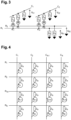
- FIG. 9 schematically illustrates, by way of illustrative example, a mode of implementation of a method for acquiring an image of a body by means of a matrix ultrasound imaging device with row-column addressing of dimensions 4x4.
- the person skilled in the art will be able to adapt the method described regardless of the number N of rows and columns of the device.
- FIG. 9 represents more particularly the signs of the bias voltages applied to the column electrodes C j of the matrix during the four successive reception phases RX1, RX2, RX3 and RX4 of the process.
- a + sign is shown at the head of the column when the bias voltage applied to the column is equal to V bias
- a - sign at the head of the column when the bias voltage applied to the column is equal to -V bias .
- the column electrodes C 1 , C 2 , C 3 and C 4 are all positively polarized (++++).
- the column electrodes C 1 , C 2 , C 3 and C 4 are respectively positively, negatively, positively and negatively polarized (+-+-).
- the column electrodes C 1 , C 2 , C 3 and C 4 are respectively positively, positively, negatively and negatively polarized (++--).
- the column electrodes C 1 , C 2 , C 3 and C 4 are respectively positively, negatively, negatively and positively polarized (+--+).
- the transducer in a first configuration of the switch system, has a first electrode connected to the electrode R i and a second electrode connected to the electrode C j , and, in a second configuration of the switch system, the transducer has its first electrode connected to the electrode C j and its second electrode connected to the electrode R i .
- the switch systems associated with the individual transducers can be controlled individually, transducer by transducer, or simultaneously by column. It will be noted that this embodiment is compatible with any type of ultrasonic transducers, including transducers not exhibiting symmetrical voltage behavior. In particular, this embodiment is not limited to CMUT and PMUT transducers.
- the described embodiments are not limited to this particular case.
- the described embodiments may be adapted to trace the individual contributions of the elementary transducers from measurements of another variable electrical quantity, for example a current, charges or an impedance, on the electrodes of the device.
- the wave is generated by the same matrix device as that used for receiving the return wave.
- the transducer array is used only as a receiving device, to receive the ultrasonic wave returned by the body to be analyzed, and a separate transmitting device (not detailed) is used to transmit the ultrasonic wave towards the body to be analyzed.
- the transmitting device and the receiving device are then synchronized to implement the N alternating TX transmission phases and the N alternating RX reception phases.
Landscapes
- Physics & Mathematics (AREA)
- Engineering & Computer Science (AREA)
- Radar, Positioning & Navigation (AREA)
- Remote Sensing (AREA)
- Acoustics & Sound (AREA)
- General Physics & Mathematics (AREA)
- Computer Networks & Wireless Communication (AREA)
- Life Sciences & Earth Sciences (AREA)
- Health & Medical Sciences (AREA)
- Chemical & Material Sciences (AREA)
- Analytical Chemistry (AREA)
- Biochemistry (AREA)
- General Health & Medical Sciences (AREA)
- Immunology (AREA)
- Pathology (AREA)
- Mechanical Engineering (AREA)
- Investigating Or Analyzing Materials By The Use Of Ultrasonic Waves (AREA)
- Ultra Sonic Daignosis Equipment (AREA)
- Transducers For Ultrasonic Waves (AREA)
Applications Claiming Priority (2)
| Application Number | Priority Date | Filing Date | Title |
|---|---|---|---|
| FR2106871A FR3124597B1 (fr) | 2021-06-25 | 2021-06-25 | Procédé et dispositif d'imagerie ultrasonore à adressage ligne-colonne |
| PCT/EP2022/065642 WO2022268512A1 (fr) | 2021-06-25 | 2022-06-09 | Procede et dispositif d'imagerie ultrasonore a adressage ligne-colonne |
Publications (2)
| Publication Number | Publication Date |
|---|---|
| EP4359784A1 EP4359784A1 (fr) | 2024-05-01 |
| EP4359784B1 true EP4359784B1 (fr) | 2025-07-02 |
Family
ID=77519286
Family Applications (1)
| Application Number | Title | Priority Date | Filing Date |
|---|---|---|---|
| EP22732210.4A Active EP4359784B1 (fr) | 2021-06-25 | 2022-06-09 | Procede et dispositif d'imagerie ultrasonore a adressage ligne-colonne |
Country Status (9)
| Country | Link |
|---|---|
| US (1) | US20240288579A1 (da) |
| EP (1) | EP4359784B1 (da) |
| JP (1) | JP2024524318A (da) |
| KR (1) | KR20240024072A (da) |
| CN (1) | CN117561441A (da) |
| CA (1) | CA3220609A1 (da) |
| DK (1) | DK4359784T3 (da) |
| FR (1) | FR3124597B1 (da) |
| WO (1) | WO2022268512A1 (da) |
Families Citing this family (1)
| Publication number | Priority date | Publication date | Assignee | Title |
|---|---|---|---|---|
| FR3149385B1 (fr) | 2023-05-29 | 2025-06-20 | Moduleus | Procédé et dispositif d'imagerie ultrasonore à adressage ligne-colonne |
Family Cites Families (11)
| Publication number | Priority date | Publication date | Assignee | Title |
|---|---|---|---|---|
| FR2106871A6 (da) | 1968-12-31 | 1972-05-05 | Albertini Prosper | |
| US9941989B2 (en) * | 2014-09-03 | 2018-04-10 | The Governors Of The University Of Alberta | Coded imaging and multi-user communications systems |
| FR3026493B1 (fr) * | 2014-09-26 | 2021-02-12 | Centre Nat Rech Scient | Procede et dispositif d'imagerie acoustique. |
| US11619730B2 (en) * | 2015-04-01 | 2023-04-04 | Verasonics, Inc. | Method and system for coded excitation imaging by impulse response estimation and retrospective acquisition |
| US11487006B2 (en) * | 2015-12-01 | 2022-11-01 | Supersonic Imagine | Imaging method, an apparatus implementing said method, a computer program and a computer-readable storage medium |
| US11213278B2 (en) * | 2017-05-19 | 2022-01-04 | Mayo Foundation For Medical Education And Research | System and method for visualization of tissue microvascular using ultrasound |
| EP3658951B1 (en) * | 2017-07-26 | 2025-04-02 | Mayo Foundation for Medical Education and Research | Methods for encoded multi-pulse contrast enhanced ultrasound imaging |
| US11852754B2 (en) * | 2017-12-12 | 2023-12-26 | Versitech Limited | Ultrafast ultrasound imaging with cascaded dual-polarity waves |
| US11150344B2 (en) * | 2018-01-26 | 2021-10-19 | Roger Zemp | 3D imaging using a bias-sensitive crossed-electrode array |
| US20200069289A1 (en) * | 2018-09-05 | 2020-03-05 | The Governors Of The University Of Alberta | Ultrasound imaging using complementary codes |
| US12569881B2 (en) * | 2021-09-09 | 2026-03-10 | Roger Zemp | Bias-switchable ultrasonic transducer array |
-
2021
- 2021-06-25 FR FR2106871A patent/FR3124597B1/fr active Active
-
2022
- 2022-06-09 JP JP2023579616A patent/JP2024524318A/ja active Pending
- 2022-06-09 WO PCT/EP2022/065642 patent/WO2022268512A1/fr not_active Ceased
- 2022-06-09 EP EP22732210.4A patent/EP4359784B1/fr active Active
- 2022-06-09 DK DK22732210.4T patent/DK4359784T3/da active
- 2022-06-09 CN CN202280045119.3A patent/CN117561441A/zh active Pending
- 2022-06-09 CA CA3220609A patent/CA3220609A1/fr active Pending
- 2022-06-09 US US18/572,192 patent/US20240288579A1/en active Pending
- 2022-06-09 KR KR1020237042389A patent/KR20240024072A/ko active Pending
Also Published As
| Publication number | Publication date |
|---|---|
| JP2024524318A (ja) | 2024-07-05 |
| DK4359784T3 (da) | 2025-08-18 |
| CA3220609A1 (fr) | 2022-12-29 |
| FR3124597A1 (fr) | 2022-12-30 |
| US20240288579A1 (en) | 2024-08-29 |
| WO2022268512A1 (fr) | 2022-12-29 |
| KR20240024072A (ko) | 2024-02-23 |
| FR3124597B1 (fr) | 2025-04-18 |
| CN117561441A (zh) | 2024-02-13 |
| EP4359784A1 (fr) | 2024-05-01 |
Similar Documents
| Publication | Publication Date | Title |
|---|---|---|
| EP0050060B1 (fr) | Système d'imagerie à émissions multiples et simultanées | |
| EP2578324B1 (en) | Large-area ultrasound contact imaging | |
| FR2920064A1 (fr) | Circuits d'emission/reception pour systemes echographiques. | |
| JPWO2006006460A1 (ja) | 超音波撮像装置 | |
| FR2993362A1 (fr) | Procede de traitement de signaux issus d'une acquisition par sondage ultrasonore, programme d'ordinateur et dispositif de sondage a ultrasons correspondants | |
| FR2946753A1 (fr) | Procede et dispositif ultrasonores pour caracteriser un milieu | |
| EP0039263A1 (fr) | Dispositif corrélateur bidimensionnel | |
| EP4359784B1 (fr) | Procede et dispositif d'imagerie ultrasonore a adressage ligne-colonne | |
| FR2478824A1 (fr) | Systeme d'imagerie acoustique | |
| EP0002642A1 (fr) | Système d'antenne à pouvoir séparateur élevé | |
| EP3987663B1 (fr) | Dispositif d'imagerie ultrasonore matriciel | |
| EP4157553B1 (fr) | Dispositif d'imagerie ultrasonore a adressage ligne-colonne | |
| WO2024074252A1 (fr) | Procede d'imagerie ultrasonore par transformee de fourier multidimensionnelle a l'aide de deux transducteurs multielements distincts | |
| FR3036192A1 (fr) | Procede et dispositif de sondage par propagation d'ondes | |
| FR3149385A1 (fr) | Procédé et dispositif d'imagerie ultrasonore à adressage ligne-colonne | |
| WO2011018573A1 (fr) | Procede pour determiner un parametre physique, procede d'imagerie et dispositif pour mettre en oeuvre ledit procede. | |
| EP1346239A1 (fr) | Dispositif pour engendrer des ondes elastiques focalisees dans un milieu materiel tel que le sous-sol, et methode pour sa mise en oeuvre | |
| FR3065079A1 (fr) | Procede et dispositif de sondage ultrasonore pour l'obtention de courbes de dispersion d'un milieu sonde | |
| FR3065078B1 (fr) | Procede et dispositif de sondage ultrasonore par focalisation adaptative au moyen d'un objet solide reverberant | |
| EP3188367B1 (fr) | Perfectionnement aux transducteurs à ondes de volume guidées en surface | |
| EP0982859A1 (fr) | Filtre acoustique à deux canaux différents à compensation de réjection | |
| FR2716007A1 (fr) | Antenne acoustique en polymère piézoélectrique et sonar comportant une telle antenne. | |
| FR3060754A1 (fr) | Dispositif et procede de caracterisation non-destructive d'un materiau | |
| WO2025002869A1 (fr) | Sonde d'imagerie ultrasonore | |
| WO2024184087A1 (fr) | Sonde d'imagerie ultrasonore |
Legal Events
| Date | Code | Title | Description |
|---|---|---|---|
| STAA | Information on the status of an ep patent application or granted ep patent |
Free format text: STATUS: UNKNOWN |
|
| STAA | Information on the status of an ep patent application or granted ep patent |
Free format text: STATUS: THE INTERNATIONAL PUBLICATION HAS BEEN MADE |
|
| PUAI | Public reference made under article 153(3) epc to a published international application that has entered the european phase |
Free format text: ORIGINAL CODE: 0009012 |
|
| STAA | Information on the status of an ep patent application or granted ep patent |
Free format text: STATUS: REQUEST FOR EXAMINATION WAS MADE |
|
| 17P | Request for examination filed |
Effective date: 20240109 |
|
| AK | Designated contracting states |
Kind code of ref document: A1 Designated state(s): AL AT BE BG CH CY CZ DE DK EE ES FI FR GB GR HR HU IE IS IT LI LT LU LV MC MK MT NL NO PL PT RO RS SE SI SK SM TR |
|
| DAV | Request for validation of the european patent (deleted) | ||
| DAX | Request for extension of the european patent (deleted) | ||
| GRAP | Despatch of communication of intention to grant a patent |
Free format text: ORIGINAL CODE: EPIDOSNIGR1 |
|
| STAA | Information on the status of an ep patent application or granted ep patent |
Free format text: STATUS: GRANT OF PATENT IS INTENDED |
|
| RIC1 | Information provided on ipc code assigned before grant |
Ipc: G01S 15/89 20060101ALI20250116BHEP Ipc: B06B 1/06 20060101ALI20250116BHEP Ipc: B06B 1/02 20060101ALI20250116BHEP Ipc: G01N 29/26 20060101ALI20250116BHEP Ipc: G01N 29/04 20060101ALI20250116BHEP Ipc: G01N 29/06 20060101AFI20250116BHEP |
|
| INTG | Intention to grant announced |
Effective date: 20250129 |
|
| GRAS | Grant fee paid |
Free format text: ORIGINAL CODE: EPIDOSNIGR3 |
|
| P01 | Opt-out of the competence of the unified patent court (upc) registered |
Free format text: CASE NUMBER: APP_16656/2025 Effective date: 20250407 |
|
| GRAA | (expected) grant |
Free format text: ORIGINAL CODE: 0009210 |
|
| STAA | Information on the status of an ep patent application or granted ep patent |
Free format text: STATUS: THE PATENT HAS BEEN GRANTED |
|
| AK | Designated contracting states |
Kind code of ref document: B1 Designated state(s): AL AT BE BG CH CY CZ DE DK EE ES FI FR GB GR HR HU IE IS IT LI LT LU LV MC MK MT NL NO PL PT RO RS SE SI SK SM TR |
|
| REG | Reference to a national code |
Ref country code: GB Ref legal event code: FG4D Free format text: NOT ENGLISH |
|
| REG | Reference to a national code |
Ref country code: CH Ref legal event code: EP |
|
| REG | Reference to a national code |
Ref country code: DE Ref legal event code: R096 Ref document number: 602022016952 Country of ref document: DE |
|
| REG | Reference to a national code |
Ref country code: IE Ref legal event code: FG4D Free format text: LANGUAGE OF EP DOCUMENT: FRENCH |
|
| REG | Reference to a national code |
Ref country code: DK Ref legal event code: T3 Effective date: 20250808 |
|
| REG | Reference to a national code |
Ref country code: NL Ref legal event code: FP |
|
| PG25 | Lapsed in a contracting state [announced via postgrant information from national office to epo] |
Ref country code: PT Free format text: LAPSE BECAUSE OF FAILURE TO SUBMIT A TRANSLATION OF THE DESCRIPTION OR TO PAY THE FEE WITHIN THE PRESCRIBED TIME-LIMIT Effective date: 20251103 |
|
| REG | Reference to a national code |
Ref country code: AT Ref legal event code: MK05 Ref document number: 1809754 Country of ref document: AT Kind code of ref document: T Effective date: 20250702 |
|
| PG25 | Lapsed in a contracting state [announced via postgrant information from national office to epo] |
Ref country code: IS Free format text: LAPSE BECAUSE OF FAILURE TO SUBMIT A TRANSLATION OF THE DESCRIPTION OR TO PAY THE FEE WITHIN THE PRESCRIBED TIME-LIMIT Effective date: 20251102 |
|
| PG25 | Lapsed in a contracting state [announced via postgrant information from national office to epo] |
Ref country code: NO Free format text: LAPSE BECAUSE OF FAILURE TO SUBMIT A TRANSLATION OF THE DESCRIPTION OR TO PAY THE FEE WITHIN THE PRESCRIBED TIME-LIMIT Effective date: 20251002 |
|
| REG | Reference to a national code |
Ref country code: LT Ref legal event code: MG9D |
|
| PG25 | Lapsed in a contracting state [announced via postgrant information from national office to epo] |
Ref country code: AT Free format text: LAPSE BECAUSE OF FAILURE TO SUBMIT A TRANSLATION OF THE DESCRIPTION OR TO PAY THE FEE WITHIN THE PRESCRIBED TIME-LIMIT Effective date: 20250702 |
|
| PG25 | Lapsed in a contracting state [announced via postgrant information from national office to epo] |
Ref country code: FI Free format text: LAPSE BECAUSE OF FAILURE TO SUBMIT A TRANSLATION OF THE DESCRIPTION OR TO PAY THE FEE WITHIN THE PRESCRIBED TIME-LIMIT Effective date: 20250702 |
|
| PG25 | Lapsed in a contracting state [announced via postgrant information from national office to epo] |
Ref country code: HR Free format text: LAPSE BECAUSE OF FAILURE TO SUBMIT A TRANSLATION OF THE DESCRIPTION OR TO PAY THE FEE WITHIN THE PRESCRIBED TIME-LIMIT Effective date: 20250702 |
|
| PG25 | Lapsed in a contracting state [announced via postgrant information from national office to epo] |
Ref country code: GR Free format text: LAPSE BECAUSE OF FAILURE TO SUBMIT A TRANSLATION OF THE DESCRIPTION OR TO PAY THE FEE WITHIN THE PRESCRIBED TIME-LIMIT Effective date: 20251003 |
|
| PG25 | Lapsed in a contracting state [announced via postgrant information from national office to epo] |
Ref country code: CZ Free format text: LAPSE BECAUSE OF FAILURE TO SUBMIT A TRANSLATION OF THE DESCRIPTION OR TO PAY THE FEE WITHIN THE PRESCRIBED TIME-LIMIT Effective date: 20250702 Ref country code: SE Free format text: LAPSE BECAUSE OF FAILURE TO SUBMIT A TRANSLATION OF THE DESCRIPTION OR TO PAY THE FEE WITHIN THE PRESCRIBED TIME-LIMIT Effective date: 20250702 |
|
| PG25 | Lapsed in a contracting state [announced via postgrant information from national office to epo] |
Ref country code: LV Free format text: LAPSE BECAUSE OF FAILURE TO SUBMIT A TRANSLATION OF THE DESCRIPTION OR TO PAY THE FEE WITHIN THE PRESCRIBED TIME-LIMIT Effective date: 20250702 |
|
| PG25 | Lapsed in a contracting state [announced via postgrant information from national office to epo] |
Ref country code: PL Free format text: LAPSE BECAUSE OF FAILURE TO SUBMIT A TRANSLATION OF THE DESCRIPTION OR TO PAY THE FEE WITHIN THE PRESCRIBED TIME-LIMIT Effective date: 20250702 Ref country code: BG Free format text: LAPSE BECAUSE OF FAILURE TO SUBMIT A TRANSLATION OF THE DESCRIPTION OR TO PAY THE FEE WITHIN THE PRESCRIBED TIME-LIMIT Effective date: 20250702 |
|
| PG25 | Lapsed in a contracting state [announced via postgrant information from national office to epo] |
Ref country code: RS Free format text: LAPSE BECAUSE OF FAILURE TO SUBMIT A TRANSLATION OF THE DESCRIPTION OR TO PAY THE FEE WITHIN THE PRESCRIBED TIME-LIMIT Effective date: 20251002 |
|
| PG25 | Lapsed in a contracting state [announced via postgrant information from national office to epo] |
Ref country code: ES Free format text: LAPSE BECAUSE OF FAILURE TO SUBMIT A TRANSLATION OF THE DESCRIPTION OR TO PAY THE FEE WITHIN THE PRESCRIBED TIME-LIMIT Effective date: 20250702 |