EP4359688B1 - Kraftfahrzeug mit einem koppelgetriebe und mit einer parksperrvorrichtung - Google Patents
Kraftfahrzeug mit einem koppelgetriebe und mit einer parksperrvorrichtung Download PDFInfo
- Publication number
- EP4359688B1 EP4359688B1 EP22730881.4A EP22730881A EP4359688B1 EP 4359688 B1 EP4359688 B1 EP 4359688B1 EP 22730881 A EP22730881 A EP 22730881A EP 4359688 B1 EP4359688 B1 EP 4359688B1
- Authority
- EP
- European Patent Office
- Prior art keywords
- coupling
- parking lock
- motor vehicle
- switching
- actuating
- Prior art date
- Legal status (The legal status is an assumption and is not a legal conclusion. Google has not performed a legal analysis and makes no representation as to the accuracy of the status listed.)
- Active
Links
Images



Classifications
-
- F—MECHANICAL ENGINEERING; LIGHTING; HEATING; WEAPONS; BLASTING
- F16—ENGINEERING ELEMENTS AND UNITS; GENERAL MEASURES FOR PRODUCING AND MAINTAINING EFFECTIVE FUNCTIONING OF MACHINES OR INSTALLATIONS; THERMAL INSULATION IN GENERAL
- F16H—GEARING
- F16H63/00—Control outputs from the control unit to change-speed- or reversing-gearings for conveying rotary motion or to other devices than the final output mechanism
- F16H63/02—Final output mechanisms therefor; Actuating means for the final output mechanisms
- F16H63/30—Constructional features of the final output mechanisms
- F16H63/34—Locking or disabling mechanisms
- F16H63/3416—Parking lock mechanisms or brakes in the transmission
-
- B—PERFORMING OPERATIONS; TRANSPORTING
- B60—VEHICLES IN GENERAL
- B60K—ARRANGEMENT OR MOUNTING OF PROPULSION UNITS OR OF TRANSMISSIONS IN VEHICLES; ARRANGEMENT OR MOUNTING OF PLURAL DIVERSE PRIME-MOVERS IN VEHICLES; AUXILIARY DRIVES FOR VEHICLES; INSTRUMENTATION OR DASHBOARDS FOR VEHICLES; ARRANGEMENTS IN CONNECTION WITH COOLING, AIR INTAKE, GAS EXHAUST OR FUEL SUPPLY OF PROPULSION UNITS IN VEHICLES
- B60K17/00—Arrangement or mounting of transmissions in vehicles
- B60K17/02—Arrangement or mounting of transmissions in vehicles characterised by arrangement, location, or kind of clutch
-
- B—PERFORMING OPERATIONS; TRANSPORTING
- B60—VEHICLES IN GENERAL
- B60K—ARRANGEMENT OR MOUNTING OF PROPULSION UNITS OR OF TRANSMISSIONS IN VEHICLES; ARRANGEMENT OR MOUNTING OF PLURAL DIVERSE PRIME-MOVERS IN VEHICLES; AUXILIARY DRIVES FOR VEHICLES; INSTRUMENTATION OR DASHBOARDS FOR VEHICLES; ARRANGEMENTS IN CONNECTION WITH COOLING, AIR INTAKE, GAS EXHAUST OR FUEL SUPPLY OF PROPULSION UNITS IN VEHICLES
- B60K17/00—Arrangement or mounting of transmissions in vehicles
- B60K17/04—Arrangement or mounting of transmissions in vehicles characterised by arrangement, location or kind of gearing
- B60K17/043—Transmission unit disposed in on near the vehicle wheel, or between the differential gear unit and the wheel
-
- B—PERFORMING OPERATIONS; TRANSPORTING
- B60—VEHICLES IN GENERAL
- B60K—ARRANGEMENT OR MOUNTING OF PROPULSION UNITS OR OF TRANSMISSIONS IN VEHICLES; ARRANGEMENT OR MOUNTING OF PLURAL DIVERSE PRIME-MOVERS IN VEHICLES; AUXILIARY DRIVES FOR VEHICLES; INSTRUMENTATION OR DASHBOARDS FOR VEHICLES; ARRANGEMENTS IN CONNECTION WITH COOLING, AIR INTAKE, GAS EXHAUST OR FUEL SUPPLY OF PROPULSION UNITS IN VEHICLES
- B60K7/00—Disposition of motor in, or adjacent to, traction wheel
- B60K7/0007—Disposition of motor in, or adjacent to, traction wheel the motor being electric
-
- F—MECHANICAL ENGINEERING; LIGHTING; HEATING; WEAPONS; BLASTING
- F16—ENGINEERING ELEMENTS AND UNITS; GENERAL MEASURES FOR PRODUCING AND MAINTAINING EFFECTIVE FUNCTIONING OF MACHINES OR INSTALLATIONS; THERMAL INSULATION IN GENERAL
- F16H—GEARING
- F16H61/00—Control functions within control units of change-speed- or reversing-gearings for conveying rotary motion ; Control of exclusively fluid gearing, friction gearing, gearings with endless flexible members or other particular types of gearing
- F16H61/04—Smoothing ratio shift
- F16H61/0403—Synchronisation before shifting
-
- F—MECHANICAL ENGINEERING; LIGHTING; HEATING; WEAPONS; BLASTING
- F16—ENGINEERING ELEMENTS AND UNITS; GENERAL MEASURES FOR PRODUCING AND MAINTAINING EFFECTIVE FUNCTIONING OF MACHINES OR INSTALLATIONS; THERMAL INSULATION IN GENERAL
- F16H—GEARING
- F16H63/00—Control outputs from the control unit to change-speed- or reversing-gearings for conveying rotary motion or to other devices than the final output mechanism
- F16H63/02—Final output mechanisms therefor; Actuating means for the final output mechanisms
- F16H63/04—Final output mechanisms therefor; Actuating means for the final output mechanisms a single final output mechanism being moved by a single final actuating mechanism
-
- F—MECHANICAL ENGINEERING; LIGHTING; HEATING; WEAPONS; BLASTING
- F16—ENGINEERING ELEMENTS AND UNITS; GENERAL MEASURES FOR PRODUCING AND MAINTAINING EFFECTIVE FUNCTIONING OF MACHINES OR INSTALLATIONS; THERMAL INSULATION IN GENERAL
- F16H—GEARING
- F16H63/00—Control outputs from the control unit to change-speed- or reversing-gearings for conveying rotary motion or to other devices than the final output mechanism
- F16H63/02—Final output mechanisms therefor; Actuating means for the final output mechanisms
- F16H63/30—Constructional features of the final output mechanisms
- F16H63/304—Constructional features of the final output mechanisms the final output mechanisms comprising elements moved by electrical or magnetic force
-
- F—MECHANICAL ENGINEERING; LIGHTING; HEATING; WEAPONS; BLASTING
- F16—ENGINEERING ELEMENTS AND UNITS; GENERAL MEASURES FOR PRODUCING AND MAINTAINING EFFECTIVE FUNCTIONING OF MACHINES OR INSTALLATIONS; THERMAL INSULATION IN GENERAL
- F16H—GEARING
- F16H63/00—Control outputs from the control unit to change-speed- or reversing-gearings for conveying rotary motion or to other devices than the final output mechanism
- F16H63/02—Final output mechanisms therefor; Actuating means for the final output mechanisms
- F16H63/30—Constructional features of the final output mechanisms
- F16H63/34—Locking or disabling mechanisms
- F16H63/3416—Parking lock mechanisms or brakes in the transmission
- F16H63/3458—Parking lock mechanisms or brakes in the transmission with electric actuating means, e.g. shift by wire
-
- F—MECHANICAL ENGINEERING; LIGHTING; HEATING; WEAPONS; BLASTING
- F16—ENGINEERING ELEMENTS AND UNITS; GENERAL MEASURES FOR PRODUCING AND MAINTAINING EFFECTIVE FUNCTIONING OF MACHINES OR INSTALLATIONS; THERMAL INSULATION IN GENERAL
- F16H—GEARING
- F16H63/00—Control outputs from the control unit to change-speed- or reversing-gearings for conveying rotary motion or to other devices than the final output mechanism
- F16H63/02—Final output mechanisms therefor; Actuating means for the final output mechanisms
- F16H63/30—Constructional features of the final output mechanisms
- F16H63/34—Locking or disabling mechanisms
- F16H63/3416—Parking lock mechanisms or brakes in the transmission
- F16H63/3458—Parking lock mechanisms or brakes in the transmission with electric actuating means, e.g. shift by wire
- F16H63/3466—Parking lock mechanisms or brakes in the transmission with electric actuating means, e.g. shift by wire using electric motors
-
- B—PERFORMING OPERATIONS; TRANSPORTING
- B60—VEHICLES IN GENERAL
- B60K—ARRANGEMENT OR MOUNTING OF PROPULSION UNITS OR OF TRANSMISSIONS IN VEHICLES; ARRANGEMENT OR MOUNTING OF PLURAL DIVERSE PRIME-MOVERS IN VEHICLES; AUXILIARY DRIVES FOR VEHICLES; INSTRUMENTATION OR DASHBOARDS FOR VEHICLES; ARRANGEMENTS IN CONNECTION WITH COOLING, AIR INTAKE, GAS EXHAUST OR FUEL SUPPLY OF PROPULSION UNITS IN VEHICLES
- B60K7/00—Disposition of motor in, or adjacent to, traction wheel
- B60K2007/0061—Disposition of motor in, or adjacent to, traction wheel the motor axle being parallel to the wheel axle
-
- B—PERFORMING OPERATIONS; TRANSPORTING
- B60—VEHICLES IN GENERAL
- B60Y—INDEXING SCHEME RELATING TO ASPECTS CROSS-CUTTING VEHICLE TECHNOLOGY
- B60Y2200/00—Type of vehicle
- B60Y2200/90—Vehicles comprising electric prime movers
- B60Y2200/91—Electric vehicles
-
- F—MECHANICAL ENGINEERING; LIGHTING; HEATING; WEAPONS; BLASTING
- F16—ENGINEERING ELEMENTS AND UNITS; GENERAL MEASURES FOR PRODUCING AND MAINTAINING EFFECTIVE FUNCTIONING OF MACHINES OR INSTALLATIONS; THERMAL INSULATION IN GENERAL
- F16H—GEARING
- F16H61/00—Control functions within control units of change-speed- or reversing-gearings for conveying rotary motion ; Control of exclusively fluid gearing, friction gearing, gearings with endless flexible members or other particular types of gearing
- F16H61/04—Smoothing ratio shift
- F16H2061/0481—Smoothing ratio shift during range shift from drive (D) or reverse (R) to neutral (N)
-
- F—MECHANICAL ENGINEERING; LIGHTING; HEATING; WEAPONS; BLASTING
- F16—ENGINEERING ELEMENTS AND UNITS; GENERAL MEASURES FOR PRODUCING AND MAINTAINING EFFECTIVE FUNCTIONING OF MACHINES OR INSTALLATIONS; THERMAL INSULATION IN GENERAL
- F16H—GEARING
- F16H61/00—Control functions within control units of change-speed- or reversing-gearings for conveying rotary motion ; Control of exclusively fluid gearing, friction gearing, gearings with endless flexible members or other particular types of gearing
- F16H61/04—Smoothing ratio shift
- F16H2061/0488—Smoothing ratio shift during range shift from neutral (N) to drive (D)
-
- F—MECHANICAL ENGINEERING; LIGHTING; HEATING; WEAPONS; BLASTING
- F16—ENGINEERING ELEMENTS AND UNITS; GENERAL MEASURES FOR PRODUCING AND MAINTAINING EFFECTIVE FUNCTIONING OF MACHINES OR INSTALLATIONS; THERMAL INSULATION IN GENERAL
- F16H—GEARING
- F16H63/00—Control outputs from the control unit to change-speed- or reversing-gearings for conveying rotary motion or to other devices than the final output mechanism
- F16H63/02—Final output mechanisms therefor; Actuating means for the final output mechanisms
- F16H63/30—Constructional features of the final output mechanisms
- F16H2063/3089—Spring assisted shift, e.g. springs for accumulating energy of shift movement and release it when clutch teeth are aligned
-
- F—MECHANICAL ENGINEERING; LIGHTING; HEATING; WEAPONS; BLASTING
- F16—ENGINEERING ELEMENTS AND UNITS; GENERAL MEASURES FOR PRODUCING AND MAINTAINING EFFECTIVE FUNCTIONING OF MACHINES OR INSTALLATIONS; THERMAL INSULATION IN GENERAL
- F16H—GEARING
- F16H2200/00—Transmissions for multiple ratios
- F16H2200/20—Transmissions using gears with orbital motion
- F16H2200/2094—Transmissions using gears with orbital motion using positive clutches, e.g. dog clutches
Definitions
- the invention relates to a motor vehicle with at least one electric drive motor for driving the motor vehicle, with at least one coupling gear which can be switched at least between a coupling position in which the electric drive motor is coupled to a drive wheel of the motor vehicle in a torque-transmitting manner, and a decoupling position in which the electric drive motor is decoupled from the drive wheel, and with a parking lock device which comprises at least one parking lock element which can be displaced between a parking lock position in which the at least one parking lock element at least indirectly blocks rotation of the drive wheel and an unlocking position in which the at least one parking lock element releases rotation of the drive wheel.
- coupling gears it is possible, for example, to interrupt the torque transmission between the electric drive motor and the drive wheels of a motor vehicle as required (decoupling position) and thus, for example, to enable the motor vehicle to coast during driving, as well as to establish the torque transmission (coupling position) in order to enable the drive wheels to be driven by the drive motor.
- Parking lock devices allow motor vehicles to be secured against rolling away while parked.
- a locking pawl on the parking lock device engages positively with a parking lock gear on the parking lock device.
- the DE 199 23 316 A1 For example, describes a drive system for a motor vehicle with a starter and generator unit arranged in a drive train with a drive shaft.
- the starter and generator unit has an electric machine operable as an electric motor with a starter function or as an electric generator and a planetary gear.
- the actuator arrangement comprises a clutch with a clutch actuating member, which is designed to interconnect a clutch input part and a clutch output part. to driveably connect or separate from each other.
- a parking lock is provided with a locking element that can be moved into a locking position to lock a locking gear, and into a release position to release the locking gear.
- a parking lock actuating member serves to actuate the locking element.
- a controllable actuator with a movable actuator control element is provided, which can be moved into at least three actuating positions and is operatively connected to the clutch actuating member and the parking lock actuating member such that in a first actuating position the parking lock is closed, in a second actuating position the clutch is closed, and in a third actuating position the clutch and the parking lock are opened.
- Similar systems are the WO 2018/095544 A1 and the US 2020/0158238 A1 as known.
- the object of the present invention is to provide a motor vehicle with a coupling gear and a parking lock device that can be operated in an improved manner. This object is achieved by a motor vehicle having the features of patent claim 1. Advantageous embodiments with expedient further developments of the invention are specified in the subclaims.
- the invention is based on a motor vehicle with at least one electric drive motor for driving the motor vehicle.
- the motor vehicle further comprises at least one coupling gear, which can be switched at least between a coupling position, in which the electric drive motor is coupled to a drive wheel of the motor vehicle in a torque-transmitting manner, and a decoupling position, in which the electric drive motor is decoupled from the drive wheel.
- the motor vehicle comprises a parking lock device, which comprises at least one parking lock element, which can be displaced between a parking lock position, in which the at least one parking lock element at least indirectly blocks rotation of the drive wheel, and an unlocking position, in which the at least one parking lock element releases rotation of the drive wheel.
- the coupling gear can preferably be switched automatically between the coupling position and the decoupling position.
- the motor vehicle comprises at least one actuating device with an actuator, which is designed, on the one hand, to actuate a clutch of the coupling mechanism, which clutch has at least one switching element and serves to switch between the coupling position and the decoupling position, and, on the other hand, to displace the at least one parking lock element between the parking lock position and the unlocking position.
- an actuator which is designed, on the one hand, to actuate a clutch of the coupling mechanism, which clutch has at least one switching element and serves to switch between the coupling position and the decoupling position, and, on the other hand, to displace the at least one parking lock element between the parking lock position and the unlocking position.
- the actuating device therefore has at least a dual function, so that the motor vehicle can be operated in an improved manner, namely with particularly low control effort and low structural effort.
- weight can be saved, particularly compared to systems known from the prior art.
- the motor vehicle can, for example, comprise a control unit by means of which, for example, the actuating device can be controlled.
- the term drive wheel can be understood in the present case to mean a drive element which has direct contact with a contact surface of the motor vehicle and can accordingly have at least one rim and a tire connected to it.
- the at least one actuating device comprises an actuating element which is adjustable by means of the actuator and which is designed, on the one hand, to exert at least one switching force on the switching element for actuating the clutch and, on the other hand, to exert at least one displacement force for displacing the at least one parking lock element between the parking lock position and the unlocked position.
- the actuating element thus fulfills a dual function, so that in particular the provision of further actuating elements is not necessary and weight can thus be saved.
- the actuating element can preferably be designed, at least in part or entirely, as a shaft which can be connected in a rotationally fixed manner to a rotor shaft of the actuator or can be designed as the rotor shaft of the actuator.
- the at least one actuating element is coupled via a second spring element of the actuating device in a force-transmitting manner, at least indirectly, preferably directly, to an eccentric element of the actuating device, by means of which the parking lock element can be displaced between the parking lock position and the unlocked position.
- This is advantageous because the second spring element can be pretensioned when the displacement force is exerted by the actuating element, so that the displacement force can accordingly act permanently on the eccentric element.
- This allows a particularly low-delay actuation of the eccentric element and, as a result, for example, a particularly low-delay displacement of the parking lock element, for example from the unlocked position to the parking lock position, as soon as this is mechanically possible.
- this may be mechanically possible if a rotational speed of a parking lock wheel of the parking lock device has a sufficiently small rotational speed value so that the parking lock element, which may be designed as a parking lock pawl, for example, can engage in the parking lock wheel and the parking lock position can thereby be set.
- the second spring element can be designed as a torsion spring. This allows adjustment of the spring travel of the second spring element as a result of the exertion of the displacement force not only to be carried out in a particularly space-saving manner, in particular without any axial length change.
- a further advantage is that the actuating element and/or the eccentric element can be inserted at least partially into a spring element opening of the second spring element, provided the second spring element is designed as a torsion spring. This allows the actuating element and/or the eccentric element to assume a further function, namely the function of holding the second spring element in a particularly captive manner.
- the invention is based on the finding that prior art systems for multiple functions also use a corresponding number of servomotors, which results in increased effort for controlling the respective servomotors to fulfill the functions.
- the invention addresses this issue and enables improved operation, in particular improved operation, of the motor vehicle by actuating both the clutch and the parking lock element with the actuating device.
- between the coupling position and the decoupling position can be understood to mean that the actuating device can be designed and used both for switching from the coupling position to the decoupling position and for (reverse) switching from the decoupling position to the coupling position. However, this does not have to be the case.
- the expression "between the coupling position and the decoupling position” can also encompass the switching from the coupling position to the decoupling position or the switching from the decoupling position to the coupling position being carried out using the actuating device.
- the actuating device can be used to move the parking lock element from the parking position to the unlocked position and vice versa, i.e. from the The actuating device can be designed and used to move the parking lock element from the unlocked position to the parked position. However, it is also conceivable that the actuating device can be designed and used to move the parking lock element either from the parked position to the unlocked position or vice versa, from the unlocked position to the parked position.
- the actuator can therefore be used and arranged both to actuate the switching element and to displace the parking lock element.
- the actuator can be coupled in a force-transmitting manner, at least indirectly, to the switching element on the one hand, and at least indirectly to the parking lock element on the other.
- the actuator can particularly preferably be designed as an electric motor.
- the electric motor can be supplied with electrical energy from the vehicle's electrical system with particularly little effort.
- the actuator in principle, however, it is also conceivable to design the actuator as a pneumatic device or as a hydraulic device, so that, for example, the actuation of the clutch and the shifting between the parking lock position and the unlock position can be effected by supplying the actuator with compressed air or hydraulic fluid.
- Designing the actuator as a pneumatic device (pneumatically operating device) or as a hydraulic device (hydraulically operating device) can be advantageous in order to enable actuation and/or emergency actuation of the switching element and the parking lock element that is independent of an electrical energy storage device and thus of the vehicle's electrical system and is therefore particularly fail-safe, by supplying the pneumatic device or hydraulic device with energy, for example, via a corresponding pressure accumulator.
- the actuator can be configured to generate a rotary movement, in particular oriented in precisely one direction of rotation, by means of which both the clutch can be actuated and the parking lock element can be displaced.
- a rotary movement In contrast to a linear movement, such a rotary movement enables particularly space-saving actuation or displacement.
- the clutch can be engaged using the shifting element.
- the shifting element can be used to move at least one clutch element of the clutch relative to another clutch element of the clutch, thereby engaging the clutch.
- the clutch can preferably be designed as a form-locking clutch.
- a form-locking clutch is one in which, in the coupled position, torque is transmitted through positive engagement, i.e., through the positive locking of the respective clutch elements.
- friction clutches such as multi-plate clutches or slip clutches
- form-locking clutches advantageously require no holding force to maintain torque transmission.
- the torque-transmitting coupling between the electric drive motor and the drive wheel can be established exclusively by switching from the uncoupling position to the coupling position.
- the motor vehicle does not include any additional clutches interposed for torque transmission between the drive wheel and the electric drive motor.
- the electric drive motor in the coupling position, can be coupled to the drive wheel via the at least one coupling gear without a differential gear, i.e., without the interposition of a differential gear of the motor vehicle and thus without a differential gear, transmitting torque.
- the electric drive motor can thus be coupled to the drive wheel via the coupling gear for independent wheel drive of the drive wheel.
- the motor vehicle comprises a plurality of drive wheels, coupling gears, and electric drive motors.
- at least one coupling gear and at least one electric drive motor can be assigned to each of the drive wheels.
- the motor vehicle has, for example, four-wheel drive, the motor vehicle can comprise four drive wheels, four electric drive motors, and four coupling gears.
- the respective front drive wheels assigned to a front end i.e., the front of the motor vehicle
- the rear drive wheels assigned to a rear end i.e., the rear of the motor vehicle
- the drive wheels are coupled by switching the (rear) coupling gears and adjusting the coupling position, and are thus used to drive the vehicle.
- the front drive wheels are in what is known as "sailing mode" and, unlike the rear drive wheels, are not used to drive the vehicle. It is of course also conceivable that the front drive wheels are used to drive the vehicle, while the rear drive wheels are in sailing mode.
- the coupling gear can be designed as a gear stage, in particular an intermediate gear stage, that can be switched between the coupling position and the decoupling position.
- the transmission can preferably be designed as an automatic transmission.
- the coupling gear can thus preferably be integrated into a spur gear of the motor vehicle. This is advantageous because the coupling gear can thereby be arranged in a particularly space-saving manner and can be accommodated in a housing of the spur gear.
- the coupling gear can preferably be designed as an intermediate gear stage of the spur gear.
- the actuating device is designed to set a release state in which the uncoupling position is engaged and, at the same time, the parking lock element is held displaced in the unlocked position.
- This is advantageous because, for example, so-called "sailing" of the motor vehicle is possible in the release state.
- the actuator maintains both the uncoupling position and the unlocked position at the same time, thereby achieving a high degree of functional reliability, especially since the actuator can be used to maintain both positions, i.e., both the uncoupling position and the unlocked position.
- the actuating device is designed to set a drive switching state in which the coupling position is switched and, at the same time, the parking lock element is held displaced in the unlocked position.
- the actuator maintains both the coupling position and the unlocked position simultaneously, thereby achieving a high degree of functional reliability, especially since the actuator can be used to maintain both positions, i.e., the coupling position and the unlocked position.
- the actuating device is designed to set a blocking switching state in which the coupling position is switched and, at the same time, the parking lock element is held displaced in the parking lock position.
- the actuator maintains both the coupling position and the parking lock position at the same time, whereby a high degree of functional reliability can be achieved, especially since the actuator can be used to maintain both positions, i.e., both the coupling position and the blocking position.
- the release state, the drive switching state, or the blocking switching state can be selectively adjusted using the actuating device, in particular using the actuator of the actuating device.
- This allows a particularly high degree of functional reliability to be achieved, especially since a situation in which the parking lock device is closed, i.e., the parking lock element is held displaced in the parking lock position, and the decoupling position is engaged at the same time, can be particularly effectively avoided.
- the switching element can be rotatably connected to the actuating element, in particular, can be rotatably mounted on the actuating element.
- the actuating element can thus also be used to support the switching element, eliminating the need for a corresponding additional bearing and thus saving weight.
- the at least one actuating element is coupled, via a first spring element of the actuating device, to the at least one switching element of the clutch in a force-transmitting manner, at least indirectly, preferably directly.
- the first spring element when exerting the switching force by means of the actuating element, can be pre-tensioned so that the switching force can act accordingly and permanently on the switching element.
- This makes it possible to achieve particularly low-delay actuation of the clutch and, as a result, for example, to achieve particularly low-delay switching from the decoupling position to the coupling position as soon as this is mechanically possible, for example as a result of the respective gearwheels of the coupling mechanism having the same speed.
- the switching force can be exerted on the switching element of the clutch.
- the switching element can thereby be moved and adjust at least one coupling element of the clutch in order to effect switching between the coupling position and the uncoupling position.
- the first spring element can be designed as a torsion spring. This allows adjustment of the spring travel of the first spring element as a result of the application of the switching force not only to be particularly space-saving, but also without any axial length change.
- a further advantage is that the actuating element and/or the switching element can be inserted, at least in part, into a spring element opening of the first spring element, provided the first spring element is designed as a torsion spring. This allows the actuating element and/or the switching element to assume a further function, namely the function of holding the first spring element in a particularly captive manner.
- the eccentric element can be designed as a cam, which allows a large cam stroke to be implemented for displacing the parking lock element even with a slight rotation of the cam.
- the eccentric element can also be designed, for example, as a circular disk mounted eccentrically, i.e., outside a central axis of the eccentric element. Such a circular disk is not only particularly easy to manufacture, but also enables particularly smooth displacement without sudden changes in travel.
- the actuating element can be rotated in one direction of rotation by means of the actuator, whereby both the at least one switching force can be exerted on the switching element via the first spring element and the at least one displacement force can be exerted on the eccentric element via the second spring element.
- the actuating element has a switching element stop, by means of which a movement of the switching element relative to the actuating element can be limited
- the actuating element has an eccentric element stop, by means of which a movement of the eccentric element relative to the actuating element can be limited.
- the switching element can have a switching element-side stop that interacts with the switching element stop, i.e., corresponds to the switching element stop, which can be in contact with the switching element stop when limiting the movement of the switching element relative to the actuating element.
- the eccentric element can have a stop on the eccentric element side which interacts with the eccentric element stop, i.e. which corresponds to the eccentric element stop and which can be in contact with the eccentric element stop when limiting the movement of the eccentric element relative to the actuating element.
- the coupling mechanism comprises a first gearwheel which is in at least indirect engagement with the drive motor, and a second gearwheel which can be coupled to the first gearwheel by means of the coupling to transmit torque and which is at least indirectly coupled to the drive wheel in a rotationally fixed manner.
- first gearwheel which is in at least indirect engagement with the drive motor
- second gearwheel which can be coupled to the first gearwheel by means of the coupling to transmit torque and which is at least indirectly coupled to the drive wheel in a rotationally fixed manner.
- the term "rotationally fixed” is generally understood to mean that a relative rotation between coupled components, for example a shaft and a gear, is prevented.
- the coupling comprises a first coupling element which is at least indirectly coupled to the first gear in a rotationally fixed manner via a second coupling element of the coupling which is connected to the first gear in a rotationally fixed manner.
- the term "indirectly” is to be understood as meaning that both the respective coupling element and the respective gear can be connected in a rotationally fixed manner, for example to a corresponding shaft, whereby the coupling element can then be indirectly coupled to the gear, for example by means of the shaft.
- the coupling comprises a connecting element which, on the one hand, is at least indirectly coupled to the second gear and, on the other hand, can be coupled to the first coupling element in a rotationally fixed manner at least indirectly, in particular by adjusting the coupling position.
- the connecting element allows a particularly simple design of the first coupling element.
- the connecting element can be reversibly detachable, i.e., non-destructively detachable, for example, by means of a spline, which can also be referred to as a plug-in spline, and at least indirectly coupled to the second gear.
- the connecting element can preferably be designed as a sleeve, in particular a fixed sleeve.
- the clutch comprises a locking element.
- the locking element is designed to prevent switching from the uncoupling position to the coupling position when there is a speed difference between the first gear and the second gear.
- the locking element is designed to release a relative movement between the first clutch element and the second clutch element, which causes switching from the uncoupling position to the coupling position, when the speeds between the first gear and the second gear are the same.
- the locking element thus advantageously prevents excessive mechanical loads, in particular the clutch elements hitting one another, as well as unwanted noises which could otherwise occur during an (unintentional) switching to the coupling position when there is a speed difference.
- the switching element in the coupling position and/or in the decoupling position is at least partially inserted into a gear recess arranged radially within a toothing of at least one of the gears and is in engagement with the first coupling element.
- This is advantageous because the at least partially arranged switching element in the gear recess, a particularly space-saving arrangement is created.
- the fact that the switching element in the gear recess engages with the first clutch element results in a particularly advantageous force flow with very few deflections and correspondingly low mechanical stresses and/or load peaks.
- the first clutch element can be arranged radially inside the gear recess both in the coupling position and in the decoupling position, thereby resulting in a correspondingly particularly advantageous arrangement with regard to the force flow.
- the switching force can, for example, be exerted on the switching element of the clutch and transmitted via the switching element to the first clutch element.
- the gear recess can also be referred to as the recess of the gear, wherein this recess is located further inwards in the radial direction of extension than the teeth of the gear.
- the switching element can have at least a first element arm section and a second element arm section directly connected to the first element arm section and enclosing an angle with the first element arm section.
- One of the element arm sections can be inserted into the gear recess and coupled to the clutch, and the other element arm section can be rotatably coupled at least indirectly, preferably directly, to the actuating device. This design allows for particularly space-saving actuation of the clutch.
- the shifting element is designed as a shift rocker or a shift fork. This is advantageous because both shift rockers and shift forks represent particularly robust forms of shifting elements.
- the shifting force can be exerted, for example, on the shifting element of the clutch.
- the shifting element can preferably be rotatably coupled to the actuating device, in particular, be rotatably mounted on the actuating device.
- Fig. 1 shows a schematic perspective view of a motor vehicle K, which comprises electric drive motors 10, spur gears SG with coupling gears 20, and drive wheels 100.
- Each of the spur gears SG is assigned one of the coupling gears 20.
- one of the coupling gears 20 is integrated into one of the spur gears SG of the motor vehicle K.
- Each of the drive machines 10 is coupled to one of the spur gears SG.
- Each of the spur gears SG can also be coupled to one of the drive wheels 100 by switching the respective coupling gear 20 of the respective spur gear SG from a decoupling position ES to a coupling position KS.
- the decoupling position ES and the coupling position KS are shown by way of example in FIG. Fig. 3 can be seen.
- the respective drive wheel 100 is coupled to the respective drive machine 10 in a torque-transmitting manner, whereas the torque transmission between the drive wheel 100 and the drive machine 10 is interrupted in the decoupling position ES.
- the respective electric drive machine 10 is decoupled from the respective drive wheel 100 in the decoupling position ES of the respective coupling gear 20. Overall, this enables selective driving of the respective drive wheels 100, thus enabling individual wheel drive of each of the drive wheels 100. Thus, each of the drive wheels 100 can be driven independently of the other drive wheels 100 by the respective electric drive machine 10 assigned to it.
- Fig. 1 only one of the spur gears SG with one of the coupling gears 20 and only one of the drive wheels 100 is shown.
- the following explanations regarding the drive machine 10, the spur gear SG, the coupling gear 20 and the drive wheel 100 apply, however, to all drive machines 10, spur gear SG, coupling gear 20 and drive wheels 100 of the motor vehicle K.
- the drive machine is in Fig. 1 hidden and therefore not visible, but in Fig. 2 shown schematically.
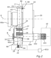
- Fig. 2 in a plan view the coupling gear 20 and thus a part of the spur gear SG.
- the spur gear SG comprises a first gear shaft 102, as shown in the plan view in Fig. 2 can be seen.
- the transmission shaft 102 is coupled to the electric drive motor 10 of the motor vehicle K in a torque-transmitting and thus rotationally fixed coupling between the first transmission shaft 102 and the drive motor 10 takes place merely by way of example via a splined shaft end section 103, in other words an end section of the first transmission shaft 102 which has a spline.
- the first transmission shaft 102 is in engagement with the electric drive motor 10 via this spline.
- a first transmission gear 104 is also rotationally fixedly coupled to the first transmission shaft 102.
- the first transmission gear 104 is in engagement with a first gear 42 of the coupling gear 20.
- the first gear 42 of the coupling gear 20 is thus in indirect engagement with the drive motor 10, i.e. is indirectly coupled to the drive motor 10.
- the spur gear SG further comprises a second gear shaft 106, which is coupled to the drive wheel 100 to transmit torque.
- the first gear shaft 102 and the second gear shaft 106 can be coupled to one another to transmit torque by means of the coupling gear 20 by adjusting the coupling position KS.
- the coupling the second gear shaft 106 with the drive wheel 100 which is shown only in sections and in a highly abstract manner, is only shown in Fig. 1
- the first gear shaft 104 serves for the input-side torque transmission and the second gear shaft 106 for the output-side torque transmission.
- the torque-transmitting and thus rotationally fixed coupling between the second gear shaft 106 and the drive gear 100 is achieved merely by way of example via an internal spline 107 of the second gear shaft 106.
- the drive gear 100 is connected to the drive gear 100 by way of a Fig. 1
- the drive shaft 110 shown in dashed lines engages with the internal spline 107 and is thus rotationally fixedly coupled to the second gear shaft 106 of the spur gear SG.
- Fig. 1 It can also be seen that the coupling gear 20 is provided for torque-transmitting coupling to exactly one side of the drive axle 110 of the motor vehicle K, whereby a single-wheel drive of the drive wheel 100 can be achieved.
- the transmission of torque between the electric drive motor 10 and the drive wheel 100 can take place without the interposition of a differential gear.
- the transmission of torque between the electric drive motor 10 and the drive wheel 100 can therefore take place without a differential gear.
- a second gear 108 of the spur gear SG is also non-rotatably coupled to the second gear shaft 106.
- the second gear 108 meshes with a second gear 52 of the coupling gear 20.
- the second gear 52 of the coupling gear 20 is at least indirectly non-rotatably coupled to the drive gear 100.
- the motor vehicle K further comprises a parking lock device 90, which comprises a parking lock element 92.
- the parking lock element 92 is designed here as a pawl.
- the parking lock element 92 can be displaced between a parking lock position P1, in which the parking lock element 92 engages with a parking lock gear 94 of the parking lock device 90 and thereby blocks rotation of the drive wheel 100, and an unlocked position P2, as shown in FIG. Fig. 5 can be seen.
- the parking lock position P1 is schematically illustrated by dashed lines of parts of the parking lock gear 94 and the parking lock element 92. In the example in Fig.
- the parking lock element 92 is not engaged with the parking lock gear 94, whereby the rotation of the drive wheel 100 is released, i.e. not blocked by the parking lock device 90.
- Fig. 2 is for example It can be seen that the parking lock gear 94 is coupled in a rotationally fixed manner to the first transmission shaft 102 as well as to the first transmission gear 104 and the electric drive motor 10. As can be seen from Fig.
- the parking lock element 92 can be rotatably mounted via a parking lock element bearing 93 on a housing not shown in more detail here, for example the housing of the spur gear SG, and can be displaced between the parking lock position P1 and the unlocked position P2 by a pivoting movement of the parking lock element 92 about the parking lock element bearing 93.
- the rolling bearings 60a, 60b are designed as adjusted cylindrical roller bearings, wherein the rolling bearing 60a serves for the rotatable mounting of the second gear 52 on the housing and the rolling bearing 60b serves for the rotatable mounting of the first gear 42 on the housing.
- a further rolling bearing 60c (see Fig. 3 ), which in this case is designed as a needle bearing, the first gear 42 is rotatably mounted and supported on a shaft 53 of the second gear 52.
- the two gears 42, 52 are supported against each other in the axial direction and thus in the direction of a rotational axis x via a further roller bearing 60e, namely an axial needle bearing.
- a further roller bearing 60e namely an axial needle bearing.
- Fig. 4 it is shown that the first transmission shaft 102 and thus the first transmission gear 104 is supported on the housing (not shown further) via a further rolling bearing 60d, which in the present case is designed as a ball bearing, for example.
- the motor vehicle K further comprises an actuating device 22 with an actuator 24.
- the actuator 24 is designed, on the one hand, to actuate a clutch 40 of the coupling mechanism 20, which clutch has at least one switching element 62 and serves to switch between the coupling position KS and the decoupling position ES.
- the actuator 24 also serves to displace the parking lock element 92 between the parking lock position P1 and the unlocking position P2.
- the switching element 62 is designed, for example, as a shift rocker or as a shift fork, as can be seen from Fig. 1 can be seen.
- the clutch 40 is designed here as a positive-locking clutch, namely as a claw clutch.
- the motor vehicle K comprises a control unit ECU, by means of which the actuating device 22 and the electric drive motor 10 can be controlled, as shown schematically in Fig. 2 is shown.
- the structure of the coupling 40 is shown by the combination of Fig. 1 with the sectional view in Fig. 3 recognizable.
- the clutch 40 comprises a first clutch element 44, which is at least indirectly, namely by means of a second clutch element 54 of the clutch 40, rotationally fixedly coupled to the first gear 42.
- the second clutch element 54 can be designed as a fixed sleeve, which can be rotationally fixedly coupled to the first gear 42.
- the second clutch element 54 is designed as a toothing, which is arranged in a gear recess 43 of the first gear 42, is integrally connected to the first gear 42, and is thereby rotationally fixedly coupled to the first gear 42.
- the toothing allows a relative axial displacement between the first coupling element 44 and the second coupling element 54 parallel to the axis of rotation x, about which the gears 42, 52 can rotate during operation of the motor vehicle K, for example in a circumferential direction U indicated by an arrow.
- the coupling 40 comprises a connecting element 70, which is directly coupled to the second gear 52 on the one hand and can be coupled in a rotationally fixed manner to the first coupling element 44 on the other hand by switching the first coupling element 44 from the decoupling position ES to the coupling position KS.
- the connecting element 70 is in engagement with the first coupling element 44 and the second gear 52 via respective splines (not designated in more detail).
- the connecting element 70 can in particular be designed as a fixed sleeve, as can be seen from Fig. 3 can be seen.
- the first coupling element 44 is brought into engagement with the connecting element 70, as shown in Fig. 3 is shown.
- the clutch 40 comprises a locking element 80.
- the locking element 80 serves to release a relative movement RB between the first clutch element 44 and the second clutch element 54, which causes switching from the decoupling position ES to the coupling position KS, when the speeds between the first gear 42 and the second gear 52 are the same.
- the locking element 80 allows the movement of the first clutch element 44 and thus the switching from the decoupling position ES to the coupling position KS, wherein in the coupling position KS the force flow KF via the first gear 42, the second Coupling element 54, the first coupling element 44, the connecting element 70 and the second gear 52 can be guided.
- the locking element 80 When the speed is equal between the first gear 42 and the second gear 52 using the electric drive motor 10, the locking element 80 therefore releases the relative movement RB between the first coupling element 44 and the second coupling element 54, which causes the switching from the decoupling position ES to the coupling position KS.
- the respective position of the first coupling element 44 is shown both in the coupling position KS and in the decoupling position ES (dashed lines). It is advantageous here if, in addition to the second coupling element 54 and the locking element 80, which are each arranged completely in the gear recess 43, the first coupling element 44 and the connecting element 70 are also arranged at least partially, preferably completely, in the gear recess 43.
- the force flow KF between the first gear 42 and the second gear 52 results in a particularly small installation space and thus extends over a particularly short distance if the first coupling element 44 is arranged in the gear recess 43 not only in the decoupling position ES but also in the coupling position KS.
- the switching element 62 serves to set the coupling position KS and the decoupling position ES.
- the switching element 62 comprises a first elementary arm section 64 and a second elementary arm section 66 which is directly connected to the first elementary arm section 64 and forms an angle with the first elementary arm section 64.
- the first elementary arm section 64 and the second elementary arm section 66 together form an L-shape, which enables a particularly space-saving and interference-free switching.
- Fig. 1 with Fig. 3 It can be seen that the switching element 62 is rotatably coupled to the first coupling element 44 via the second element arm section 66.
- the switching element 62 in particular on the second element arm section 66, can have an engagement element 63, for example a sliding block, or an engagement region, which is inserted into an engagement groove 45 of the first coupling element 44, which extends at least partially in the circumferential direction U.
- the engagement element 63 is in Fig. 1 recognizable and schematic in Fig. 3 shown.
- the switching element arm sections 64, 66 can be pivoted and thereby a displacement of the first Coupling element 44 between the coupling position KS and the decoupling position ES.
- the actuating device 22 comprises an actuating element 26 which is adjustable by means of the actuator 24 and which is designed, on the one hand, to exert a switching force F_SK on the switching element 62 for actuating the clutch 40 and, on the other hand, to exert a displacement force F_VK for displacing the parking lock element 92 between the parking lock position P1 and the unlocked position P2.
- the actuating element 26 is, for example, in Fig. 1 and in sectional view in Fig. 5 shown.
- the actuating element 26 can preferably be designed as a shaft. This shaft can be connected in a rotationally fixed manner to a rotor shaft of the actuator 24. Alternatively, the actuating element 26 can also be designed as a rotor shaft of the actuator 24.
- the switching element 62 can be inserted into an actuating element recess 25 of the actuating element 26 and rotatably mounted there.
- the actuating element 26 is directly coupled to the switching element 62 of the clutch 40 in a force-transmitting manner via a first spring element 27 of the actuating device 22, designed as a torsion spring.
- actuating element 26 is coupled via a second spring element 28 of the actuating device 22, also designed as a torsion spring, in a directly force-transmitting manner to an eccentric element 30 of the actuating device 30, by means of which the parking lock element 92 can be displaced between the parking lock position P1 and the unlocked position P2.
- the eccentric element 30 is designed as a cam, as can be seen from Fig. 4 can be seen.
- the eccentric element 30 could also be designed as an eccentrically mounted circular disk, although this is not shown further here.
- the actuating element 26 can generally be rotated in a direction of rotation D1 by operating the actuator 24, whereby both the switching force F_SK can be exerted on the switching element 62 via the first spring element 27 and the displacement force F_VK can be exerted on the eccentric element 30 via the second spring element 28.
- actuating device 22 maintains a drive switching state in which the coupling position KS is switched and at the same time the parking lock element 92 is held displaced in the unlocked position P2.
- the driving of the motor vehicle K is achieved by coupling the electric drive machine 10 via the coupling gear 20 with the drive wheel 100 is secured and at the same time the parking lock element 92 is open and thus held in the unlocked position ES.
- the motor vehicle K can, for example, be operated in a so-called coasting mode, i.e., a so-called coasting of the motor vehicle K can be enabled, in which the motor vehicle K is moved without the respective electric drive motors 10 driving the respective drive wheels 100 and without the respective parking lock device 90 blocking the movement of the motor vehicle K, in particular the rolling of the respective drive wheels 100.
- the decoupling position ES is switched and, at the same time, the parking lock element 92 is held displaced in the unlocked position P2.
- the parking lock element 92 which is rotatably mounted on the housing, is pressed against the eccentric element 30 against the force of gravity by means of a third spring element 29, which is assigned, for example, to the actuating device 22 and which - like the first spring element 27 and the second spring element 28 - is designed as a torsion spring, and is held there in the unlocked position P2.
- an eccentric element-side stop 32 which is designed as a projection and can also be referred to as a stop associated with the eccentric element 30, rests against an eccentric element stop 38.
- the eccentric element stop 38 associated with the actuating element 26 is also designed as a projection in the present case, as is particularly clear in Fig. 4 and also in Fig. 2 can be seen.
- a switching element-side stop 34 which is designed as a projection and can also be referred to as a stop associated with the switching element 62, rests against a switching element stop 37 of the actuating element 26.
- the switching element stop 37 associated with the actuating element 26 is also designed as a projection in the present case, as can be seen from Fig. 1 and Fig. 2 can be seen
- a movement, in particular rotation, of the switching element 62 relative to the actuating element 26 can be limited.
- a movement, in particular rotation, of the eccentric element 30, which is rotatably mounted on the actuating element 26, relative to the actuating element 26 can be limited.
- the actuating device 22 can also be used to set the drive switching state, in which, as mentioned, the coupling position KS is switched and at the same time the Parking lock element 92 is held displaced in the unlocked position P2.
- the drive wheel 100 is coupled to the electric drive motor 10 via the spur gear SG and thus also the coupling gear 20, and the parking lock device 90 is open, so that the drive wheel 100 can be driven by the electric drive motor 10 without the parking lock device 90 blocking the drive of the drive wheel 100.
- the actuating element 26 can be moved using the actuator 24 according to the Fig. 2 and in Fig. 3 rotated in the direction of rotation D1 (here: clockwise) indicated by an arrow. If the speeds between the gears 42, 52 are not the same, the locking element 80 prevents switching from the uncoupling position ES to the coupling position KS and thus the corresponding relative movement RB of the first coupling element 44 by means of the switching element 62.
- the actuator 24 exerts a torque, by means of which the first spring element 27 is mechanically preloaded and the switching force F_SK is thereby stored in the first spring element 27 as long as the locking element 80 prevents the coupling of the first coupling element 44 with the connecting element 70 and thus the setting of the coupling position KS.
- the first coupling element 44 is pressed by means of the first spring element 27 via the switching element 62 and the engagement element 63 arranged in the engagement groove 45, so to speak, based on the switching force F_SK, in the direction of the locking element 80.
- the locking element 80 prevents the coupling of the first clutch element 44 with the connecting element 70 as long as the speed difference between the first gear 42 and the second gear 52 exists.
- the locking element 80 releases the coupling of the first clutch element 44 with the connecting element 70 and thus the setting of the coupling position KS.
- the second spring element 28 via which the eccentric element 30 and the actuating element 26 are coupled to one another in a force-transmitting manner, is also preloaded.
- the torque exerted by the actuator 24 can mechanically preload the second spring element 28 and thereby store the displacement force F_VK in the second spring element 28 when the displacement of the parking lock element 92 from the unlocked position P2 to the parking lock position P1 is mechanically prevented.
- the displacement from the unlocked position P2 to the parking lock position P1 can, for example, be mechanically prevented when the parking lock element 92 and the parking lock gear 94 are as shown in Fig. 1 shown are oriented towards one another, i.e.
- the parking lock element 92 when the parking lock element 92 cannot engage with the parking lock element 94. If a speed of the first transmission shaft 102 falls below a predetermined speed limit, i.e. the speed of the first transmission shaft is sufficiently low, which can be the case, for example, when the driving speed of the motor vehicle K is less than 5 km/h, the parking lock element 92 (here: pawl) can be brought into engagement with the parking lock gear 94, i.e. the parking lock element 92 can be displaced from the unlocked position P2 into the parking lock position PP1.
- a predetermined speed limit i.e. the speed of the first transmission shaft is sufficiently low
- the eccentric element 30 is rotated in the (first) direction of rotation D1 by the displacement force F_VK stored in the second spring element 28 and presses the parking lock element 92 into a position in which the parking lock element 92 is locked with the parking lock gear 94 and the parking lock position P1 is thus set.
- both the coupling position KS is engaged and the parking lock element 92 is simultaneously held displaced in the parking lock position P1, so that a blocking switching state is established.
- the motor vehicle K can then be held stationary using the parking lock device 90.
- the first coupling element 44 can be moved via the first spring element 27, in particular by at least partially relaxing the first spring element 27 and thereby pivoting the element arm sections 64, 66, and can be moved from the decoupling position ES into the Coupling position KS can be switched.
- the parking lock element 92 can be moved by means of the eccentric element 30 via the second spring element 28, in particular by at least partially relaxing the second spring element 28, against a spring force of the third spring element 29 and moved from the unlocked position P2 into the parking lock position P1.
- the actuating element 26 can be rotated in a second rotational direction D2, opposite to the first rotational direction D1, by operating the actuator 24.
- the switching element stop 37 as well as the switching element-side stop 34 and/or the eccentric element stop 38 and the eccentric element-side stop 32 are particularly useful, since the respective corresponding stops 37, 34 and 38, 32 enable reliable resetting of the switching element 62 and/or the eccentric element 30 and thus reliable setting of the decoupling position ES and the unlocking position PS.
- motor vehicle K A key advantage of motor vehicle K is that the described arrangement reliably eliminates an undesirable switching state in which the parking lock position P1 and the decoupling position ES are simultaneously engaged. Thus, motor vehicle K exhibits a particularly high degree of functional reliability.
Landscapes
- Engineering & Computer Science (AREA)
- General Engineering & Computer Science (AREA)
- Mechanical Engineering (AREA)
- Chemical & Material Sciences (AREA)
- Combustion & Propulsion (AREA)
- Transportation (AREA)
- Gear-Shifting Mechanisms (AREA)
Description
- Die Erfindung betrifft ein Kraftfahrzeug mit wenigstens einer elektrischen Antriebsmaschine, zum Antreiben des Kraftfahrzeugs, mit wenigstens einem Koppelgetriebe, welches zumindest zwischen einer Koppelungsstellung, in welcher die elektrische Antriebsmaschine Drehmoment übertragend mit einem Antriebsrad des Kraftfahrzeugs gekoppelt ist, und einer Entkoppelungsstellung, in welcher die elektrische Antriebsmaschine von dem Antriebsrad entkoppelt ist, schaltbar ist, und mit einer Parksperrvorrichtung, welche zumindest ein Parksperrelement umfasst, das zwischen einer Parksperrstellung, in welcher das zumindest eine Parksperrelement eine Drehung des Antriebsrades zumindest mittelbar blockiert und einer Entsperrstellung, in welcher das zumindest eine Parksperrelement die Drehung des Antriebsrades freigibt, verlagerbar ist.
- Anhand derartiger Koppelgetriebe ist es beispielsweise möglich, eine Drehmomentübertragung zwischen der elektrischen Antriebsmaschine und Antriebsrädern eines Kraftfahrzeugs bedarfsgerecht zu unterbrechen (Entkoppelungsstellung) und damit beispielsweise ein sogenanntes Segeln des Kraftfahrzeugs bei dessen Fahrbetrieb zu ermöglichen, sowie die Drehmomentübertragung herzustellen (Koppelungsstellung) um ein Antreiben der Antriebsräder mittels der Antriebsmaschine zu ermöglichen.
- Parksperrvorrichtungen hingegen ermöglichen ein Sichern von Kraftfahrzeugen in deren geparktem Zustand gegen Wegrollen. Üblicherweise rastet hierzu eine Sperrklinke der Parksperrenvorrichtung formschlüssig in ein Parksperrenrad der Parksperrenvorrichtung ein.
- Die
DE 199 23 316 A1 beschreibt beispielsweise ein Antriebssystem für ein Kraftfahrzeug mit einer in einem Antriebsstrang mit einer Antriebswelle angeordneten Starter- und Generator-Einheit. Die Starter- und Generator-Einheit weist eine als elektrischer Motor mit Starterfunktion oder elektrischer Generator betreibbare elektrische Maschine und ein Planetengetriebe auf. - Aus der
WO 2020/001778 A1 ist eine Aktuatoranordnung zum Betätigen einer Kupplung und einer Parksperre in einem Antriebsstrang eines Kraftfahrzeugs bekannt. Die Aktuatoranordnung umfasst eine Kupplung mit einem Kupplungsbetätigungsglied, das ausgestaltet ist, um ein Kupplungseingangsteil und ein Kupplungsausgangsteil miteinander antriebsmäßig zu verbinden oder voneinander zu trennen. Zudem ist eine Parksperre mit einem Sperrelement vorgesehen, das in eine Sperrposition überführbar ist, um ein Sperrenrad zu blockieren, und in eine Freigabeposition, um das Sperrenrad freizugeben. Ein Parksperrenbetätigungsglied dient zum Betätigen des Sperrelements. Weiterhin ist ein steuerbarer Aktuator mit einem bewegbaren Aktuator-Stellglied vorgesehen, das in mindestens drei Stellpositionen überführbar ist und mit dem Kupplungsbetätigungsglied und mit dem Parksperrenbetätigungsglied derart wirkverbunden ist, dass in einer ersten Stellposition die Parksperre geschlossen wird, in einer zweiten Stellposition die Kupplung geschlossen wird, und in einer dritten Stellposition die Kupplung und die Parksperre geöffnet werden. Weitere Beispiele für ähnliche Systeme sind derWO 2018/095544 A1 und derUS 2020/0158238 A1 als bekannt zu entnehmen. - Aufgabe der vorliegenden Erfindung ist es, ein Kraftfahrzeug mit einem Koppelgetriebe und einer Parksperrenvorrichtung bereitzustellen, welches auf verbesserte Weise bedienbar ist. Diese Aufgabe wird durch ein Kraftfahrzeug mit den Merkmalen des Patentanspruchs 1 gelöst. Vorteilhafte Ausgestaltungen mit zweckmäßigen Weiterbildungen der Erfindung sind in den Unteransprüchen angegeben.
- Die Erfindung geht aus von einem Kraftfahrzeug mit wenigstens einer elektrischen Antriebsmaschine, zum Antreiben des Kraftfahrzeugs. Das Kraftfahrzeug umfasst des Weiteren wenigstens ein Koppelgetriebe, welches zumindest zwischen einer Koppelungsstellung, in welcher die elektrische Antriebsmaschine Drehmoment übertragend mit einem Antriebsrad des Kraftfahrzeugs gekoppelt ist, und einer Entkoppelungsstellung, in welcher die elektrische Antriebsmaschine von dem Antriebsrad entkoppelt ist, schaltbar ist. Darüber hinaus umfasst das Kraftfahrzeug eine Parksperrvorrichtung, welche zumindest ein Parksperrelement umfasst, das zwischen einer Parksperrstellung, in welcher das zumindest eine Parksperrelement eine Drehung des Antriebsrades zumindest mittelbar blockiert und einer Entsperrstellung, in welcher das zumindest eine Parksperrelement die Drehung des Antriebsrades freigibt, verlagerbar ist. Das Koppelgetriebe kann vorzugsweise automatisiert zwischen der Koppelungsstellung und der Entkoppelungsstellung schaltbar sein.
- Zudem ist vorgesehen, dass das Kraftfahrzeug wenigstens eine Betätigungsvorrichtung mit einem Aktuator umfasst, welche einerseits zum Betätigen einer, wenigstens ein Schaltelement aufweisenden Kupplung des Koppelgetriebes, die zum Schalten zwischen der Koppelungsstellung und der Entkoppelungsstellung dient, ausgebildet ist, und andererseits zum Verlagern des zumindest einen Parksperrelements zwischen der Parksperrstellung und der Entsperrstellung ausgebildet ist. Dies ist von Vorteil, da anhand der Betätigungsvorrichtung somit einerseits die Kupplung betätigt und dadurch das Schalten zwischen der Koppelungsstellung und der Entkoppelungsstellung bewirkt werden kann und andererseits anhand dieser Betätigungsvorrichtung auch das Verlagern zwischen der Parksperrstellung und der Entsperrstellung bewirkt werden kann. Der Betätigungsvorrichtung kommt somit zumindest eine Doppelfunktion zu, sodass das Kraftfahrzeug auf verbesserte Weise, nämlich unter besonders geringem Ansteuerungsaufwand und geringem baulichen Aufwand, bedient werden kann. Zudem kann insbesondere im Vergleich zu aus dem Stand der Technik bekannten Systemen Gewicht eingespart werden. Das Kraftfahrzeug kann beispielsweise ein Steuergerät umfassen, mittels welchem beispielsweise die Betätigungsvorrichtung ansteuerbar sein kann. Unter dem Ausdruck Antriebsrad kann vorliegend ein Antriebselement verstanden werden, welches direkten Kontakt zu einer Aufstandsfläche des Kraftfahrzeugs aufweist und dementsprechend zumindest eine Felge und einen mit dieser verbundenen Reifen aufweisen kann.
- Des Weiteren ist vorgesehen, dass die wenigstens eine Betätigungsvorrichtung ein mittels des Aktuators verstellbares Betätigungselement umfasst, welches einerseits zum Ausüben zumindest einer Schaltkraft auf das Schaltelement zum Betätigen der Kupplung und andererseits zum Ausüben wenigstens einer Verlagerungskraft, zum Verlagern des zumindest einen Parksperrelements zwischen der Parksperrstellung und der Entsperrstellung ausgebildet ist. Dies ist von Vorteil, da das Betätigungselement damit eine Doppelfunktion erfüllt, sodass insbesondere auf ein Vorsehen von weiteren Betätigungselementen verzichtet und dadurch Gewicht eingespart werden kann. Das Betätigungselement kann bevorzugt zumindest bereichsweise oder vollständig als Welle ausgebildet sein, welche drehfest mit einer Rotorwelle des Aktuators verbunden oder als Rotorwelle des Aktuators ausgebildet sein kann.
- Gemäß der Erfindung ist vorgesehen, dass das wenigstens eine Betätigungselement über ein zweites Federelement der Betätigungsvorrichtung kraftübertragend zumindest mittelbar, bevorzugt unmittelbar, mit einem Exzenterelement der Betätigungsvorrichtung gekoppelt ist, mittels welchem das Parksperrelement zwischen der Parksperrstellung und der Entsperrstellung verlagerbar ist. Dies ist von Vorteil, da das zweite Federelement beim Ausüben der Verlagerungskraft mittels des Betätigungselements vorgespannt werden kann, sodass die Verlagerungskraft dementsprechend dauerhaft auf das Exzenterelement wirken kann. Hierdurch kann ein besonders verzögerungsarmes Betätigen des Exzenterelements erzielt werden und infolgedessen beispielsweise ein besonders verzögerungsarmes Verlagern des Parksperrelements, beispielsweise von der Entsperrstellung in die Parksperrstellung, erzielt werden, sobald dies mechanisch möglich ist. Dies kann beispielsweise dann mechanisch möglich sein, wenn eine Drehgeschwindigkeit eines Parksperrenrades der Parksperrvorrichtung einen ausreichend kleinen Drehgeschwindigkeitswert aufweist, sodass das Parksperrelement, welches beispielsweise als Parksperrenklinke ausgebildet sein kann, in das Parksperrenrad einrasten und dadurch die Parksperrstellung eingestellt werden kann.
- Das zweite Federelement kann als Drehfeder ausgebildet sein. Dadurch kann eine Einstellung eines Federweges des zweiten Federelements infolge des Ausübens der Verlagerungskraft nicht nur besonders platzsparend, insbesondere ohne axiale Längenänderung, erfolgen. Ein weiterer Vorteil besteht darin, dass das Betätigungselement und/oder das Exzenterelement zumindest bereichsweise in eine Federelementöffnung des zweiten Federelements eingeführt sein kann, sofern das zweite Federelement als Drehfeder ausgebildet ist. Dadurch kann das Betätigungselement und/oder das Exzenterelement eine weitere Funktion übernehmen, nämlich die Funktion des besonders verliersicheren Haltens des zweiten Federelements.
- Der Erfindung liegt die Erkenntnis zugrunde, dass bei aus dem Stand der Technik bekannten Systemen für mehrere Funktionen auch eine entsprechende Anzahl an Stellmotoren eingesetzt werden, womit ein erhöhter Aufwand zur Ansteuerung der jeweiligen Stellmotoren zur Erfüllung der Funktionen verbunden ist. Die Erfindung setzt hier an und ermöglicht durch das Betätigen sowohl der Kupplung als auch des Parksperrelements durch die Betätigungsvorrichtung eine verbesserte Bedienung, insbesondere einen verbesserten Betrieb, des Kraftfahrzeugs.
- Unter dem Ausdruck "zwischen der Koppelungsstellung und der Entkoppelungsstellung" kann verstanden werden, dass die Betätigungsvorrichtung zwar sowohl zum Schalten von der Koppelungsstellung in die Entkoppelungsstellung als auch zum (umgekehrten) Schalten von der Entkoppelungsstellung in die Koppelungsstellung ausgebildet sein und herangezogen werden kann. Dies muss jedoch nicht der Fall sein. Von dem Ausdruck "zwischen der Koppelungsstellung und der Entkoppelungsstellung" kann auch umfasst sein, dass entweder das Schalten von der Koppelungsstellung in die Entkoppelungsstellung oder das Schalten von der Entkoppelungsstellung in die Koppelungsstellung anhand der Betätigungsvorrichtung erfolgt.
- Dies gilt analog auch für das Verlagern des Parksperrelements zwischen der Parksperrstellung und der Entsperrstellung. Die Betätigungsvorrichtung kann sowohl zum Verlagen von der Parkstellung in die Entsperrstellung und umgekehrt, also von der Entsperrstellung in die Parkstellung ausgebildet sein und dazu herangezogen werden. Denkbar ist jedoch auch, dass die Betätigungsvorrichtung entweder zum Verlagern des Parksperrelements von der Parksperrstellung in die Entsperrstellung oder umgekehrt, von der Entsperrstellung in die Parkstellung ausgebildet sein und herangezogen werden kann.
- Der Aktuator kann also sowohl zum Betätigen des Schaltelements als auch zum Verlagern des Parksperrelements eingesetzt werden und angeordnet sein. Hierzu kann der Aktuator einerseits zumindest mittelbar mit dem Schaltelement und andererseits zumindest mittelbar mit dem Parksperrelement kraftübertragend gekoppelt sein.
- Der Aktuator kann im Rahmen der vorliegenden Erfindung besonders bevorzugt als Elektromotor ausgebildet sein. Der Elektromotor kann besonders aufwandsarm aus einem Bordnetz des Kraftfahrzeugs mit elektrischer Energie versorgt werden.
- Denkbar ist jedoch prinzipiell auch eine Ausgestaltung des Aktuators als Pneumatikvorrichtung oder als Hydraulikvorrichtung, sodass beispielsweise die Betätigung der Kupplung sowie das Verlagern zwischen der Parksperrstellung und der Entsperrstellung durch Versorgung des Aktuators mit Druckluft bzw. Hydraulikflüssigkeit bewirkt werden kann. Die Ausgestaltung des Aktuators als Pneumatikvorrichtung (pneumatisch arbeitende Vorrichtung) oder als Hydraulikvorrichtung (hydraulisch arbeitende Vorrichtung) kann von Vorteil sein, um eine von einem elektrischen Energiespeicher und damit von dem Bordnetz des Kraftfahrzeugs unabhängige und damit besonders ausfallsichere Betätigung und/oder Notbetätigung des Schaltelements und des Parksperrelements zu ermöglichen, indem die Pneumatikvorrichtung bzw. Hydraulikvorrichtung beispielsweise über einen entsprechenden Druckspeicher mit Energie versorgt wird.
- Bevorzugt kann der Aktuator zur Erzeugung einer, insbesondere in genau eine Drehrichtung orientierten, Drehbewegung ausgebildet sein, mittels welcher sowohl die Kupplung betätigbar als auch das Parksperrelement verlagerbar ist. Eine derartige Drehbewegung ermöglicht im Gegensatz zu einer Linearbewegung eine besonders platzsparende Betätigung bzw. Verlagerung.
- Mittels des Schaltelements kann die Kupplung geschaltet werden. So kann mittels des Schaltelements beispielsweise wenigstens ein Kupplungselement der Kupplung relativ zu einem anderen Kupplungselement der Kupplung bewegt und dadurch die Kupplung geschaltet werden.
- Die Kupplung kann vorzugsweise als Formschlusskupplung ausgebildet sein. Unter der Formschlusskupplung ist eine Kupplung zu verstehen, bei welcher in der Koppelungsstellung eine Übertragung von Drehmoment durch formschlüssiges Ineinandergreifen, also durch Formschluss der jeweiligen Kupplungselemente der Kupplung erfolgt. Anders als bei Kupplungen, welche Drehmoment durch Reibschluss übertragen, also Reibkupplungen, wie beispielsweise Lamellenkupplungen oder Rutschkupplungen, ist bei Formschlusskupplungen in vorteilhafter Weise keine Haltekraft nötig, um die Übertragung des Drehmoments aufrecht zu erhalten. Darüber hinaus tritt bei Formschlusskupplungen auch kein Schlupf zwischen den jeweiligen Kupplungselementen auf, über welche in der Koppelungsstellung Drehmoment übertragbar ist, bzw. übertragen wird. Dies trägt zur Effizienzsteigerung bei und ermöglicht insgesamt einen aufwandsarmen Betrieb des Koppelgetriebes und damit auch des Kraftfahrzeugs.
- Bevorzugt kann ausschließlich durch Schalten von der Entkoppelungsstellung in die Koppelungsstellung die Drehmoment übertragende Koppelung zwischen der elektrischen Antriebsmaschine und dem Antriebsrad hergestellt werden. Es kann also vorgesehen sein, dass das Kraftfahrzeug keine weiteren Kupplungen umfasst, welche zur Drehmomentübertragung zwischen dem Antriebsrad und der elektrischen Antriebsmaschine zwischengeschaltet sind.
- In vorteilhafter Weise kann die elektrische Antriebsmaschine in der Koppelungsstellung über das wenigstens eine Koppelgetriebe differenzialgetriebelos, also mit anderen Worten ohne Zwischenschaltung eines Differenzialgetriebes des Kraftfahrzeugs und damit differenzialgetriebefrei Drehmoment übertragend mit dem Antriebsrad gekoppelt sein. Die elektrische Antriebsmaschine kann über das Koppelgetriebe somit zum Einzelradantrieb des Antriebsrades mit dem Antriebsrad gekoppelt werden.
- Vorzugsweise kann vorgesehen sein, dass das Kraftfahrzeug eine Mehrzahl an Antriebsrädern, Koppelgetrieben und elektrischen Antriebsmaschinen umfasst. So kann jedem der Antriebsräder jeweils wenigstens ein Koppelgetriebe und wenigstens eine elektrische Antriebsmaschine zugeordnet sein. Weist das Kraftfahrzeug also beispielsweise einen Vierradantrieb auf, so kann das Kraftfahrzeug vier Antriebsräder, vier elektrische Antriebsmaschinen und vier Koppelgetriebe umfassen. Dadurch können beispielsweise die jeweiligen, einem Vorderwagen, also der Front des Kraftfahrzeugs zugeordneten, vorderen Antriebsräder durch Schalten der diesen vorderen Antriebsrädern zugeordneten (vorderen) Koppelgetriebe und Einstellen der Entkoppelungsstellung entkoppelt werden, wohingegen die einem Hinterwagen, also dem Heck des Kraftfahrzeugs zugeordneten, hinteren Antriebsräder durch Schalten der (hinteren) Koppelgetriebe und Einstellen der Koppelungsstellung gekoppelt und damit zum Antreiben des Kraftfahrzeugs genutzt werden. In diesem beispielhaften Fall befinden sich die vorderen Antriebsräder in einem sogenannten "Segelbetrieb" und werden im Gegensatz zu den hinteren Antriebsrädern nicht zum Antreiben des Kraftfahrzeugs genutzt. Denkbar ist selbstverständlich auch, dass die vorderen Antriebsräder zum Antreiben des Kraftfahrzeugs genutzt werden und sich die hinteren Antriebsräder im Segelbetrieb befinden.
- Besonders bevorzugt kann das Koppelgetriebe als zwischen der Koppelungsstellung und der Entkoppelungsstellung schaltbare Zahnradstufe, insbesondere Zwischenzahnradstufe, ausgebildet sein. Dies gestattet eine einfache Integration in ein Getriebe, insbesondere Stirnradgetriebe, des Kraftfahrzeugs. Das Getriebe kann vorzugsweise als Automatikgetriebe ausgestaltet sein. Das Koppelgetriebe kann somit bevorzugt in ein Stirnradgetriebe des Kraftfahrzeugs integriert sein. Dies ist von Vorteil, da das Koppelgetriebe dadurch besonders bauraumsparend angeordnet und in einem Gehäuse des Stirnradgetriebes aufgenommen sein kann. Vorzugsweise kann das Koppelgetriebe als Zwischenzahnradstufe des Stirnradgetriebes ausgebildet sein.
- In einer vorteilhaften Weiterbildung der Erfindung ist vorgesehen, dass die Betätigungsvorrichtung dazu ausgebildet ist, einen Freigabezustand einzustellen, bei welchem die Entkoppelungsstellung geschaltet und gleichzeitig das Parksperrelement in der Entsperrstellung verlagert gehalten ist. Dies ist von Vorteil, da in dem Freigabezustand beispielsweise ein sogenanntes "Segeln" des Kraftfahrzeugs ermöglicht ist. So kann sichergestellt werden, dass Bewegungsenergie des Kraftfahrzeugs zu dessen Fortbewegung genutzt wird, anstatt zumindest Teile der Bewegungsenergie durch einen Schleppbetrieb der elektrischen Antriebsmaschine zu verlieren. Bevorzugt hält der Aktuator dabei sowohl die Entkoppelungsstellung als auch gleichzeitig die Entsperrstellung aufrecht, wodurch ein hohes Maß an Funktionssicherheit erzielt werden kann, zumal der Aktuator zur Aufrechterhaltung beider Stellungen, also sowohl der Entkoppelungsstellung als auch der Entsperrstellung, genutzt werden kann.
- In einer weiteren vorteilhaften Weiterbildung der Erfindung ist vorgesehen, dass die Betätigungsvorrichtung dazu ausgebildet ist, einen Antriebsschaltzustand einzustellen, bei welchem die Koppelungsstellung geschaltet und gleichzeitig das Parksperrelement in der Entsperrstellung verlagert gehalten ist. Dies ist von Vorteil, da bei dem Antriebsschaltzustand das Antreiben des Kraftfahrzeugs durch Koppelung der elektrischen Antriebsmaschine über das Koppelgetriebe mit dem Antriebsrad sichergestellt und gleichzeitig das Parksperrelement offen und damit in der Entsperrstellung gehalten ist. Bevorzugt hält der Aktuator dabei sowohl die Koppelungsstellung als auch gleichzeitig die Entsperrstellung aufrecht, wodurch ein hohes Maß an Funktionssicherheit erzielt werden kann, zumal der Aktuator zur Aufrechterhaltung beider Stellungen, also sowohl der Koppelungsstellung als auch der Entsperrstellung, genutzt werden kann.
- In einer weiteren vorteilhaften Weiterbildung der Erfindung ist vorgesehen, dass die Betätigungsvorrichtung dazu ausgebildet ist, einen Blockierschaltzustand einzustellen, bei welchem die Koppelungsstellung geschaltet und gleichzeitig das Parksperrelement in der Parksperrstellung verlagert gehalten ist. Dies ist von Vorteil, da das Antriebsrad bei dem Blockierschaltzustand sowohl mittels der elektrischen Antriebsmaschine als auch mittels der Parksperrvorrichtung gehalten werden kann, sodass ein unerwünschtes Wegrollen des Kraftfahrzeugs besonders wirksam vermieden werden kann. Bevorzugt hält der Aktuator dabei sowohl die Koppelungsstellung als auch gleichzeitig die Parksperrstellung aufrecht, wodurch ein hohes Maß an Funktionssicherheit erzielt werden kann, zumal der Aktuator zur Aufrechterhaltung beider Stellungen, also sowohl der Koppelungsstellung als auch der Sperrstellung, genutzt werden kann.
- Somit kann anhand der Betätigungsvorrichtung, insbesondere anhand des Aktuators der Betätigungsvorrichtung, wahlweise der Freigabezustand, der Antriebsschaltzustand oder der Blockierschaltzustand einstellbar sein. Hierdurch kann ein besonders hohes Maß an Funktionssicherheit erzielt werden, zumal auf besonders wirksame Weise eine Situation vermieden werden kann, in welcher die Parksperrvorrichtung geschlossen, also das Parksperrelement in der Parksperrstellung verlagert gehalten und gleichzeitig die Entkoppelungsstellung geschaltet ist.
- Bevorzugt kann das Schaltelement drehbar mit dem Betätigungselement verbunden sein, insbesondere drehbar an dem Betätigungselement gelagert sein. Dies ist von Vorteil, da das Betätigungselement somit auch zur Lagerung des Schaltelements herangezogen werden kann, sodass auf ein entsprechendes, zusätzliches Lager verzichtet und damit Gewicht eingespart werden kann.
- In einer weiteren vorteilhaften Weiterbildung der Erfindung ist vorgesehen, dass das wenigstens eine Betätigungselement über ein erstes Federelement der Betätigungsvorrichtung kraftübertragend zumindest mittelbar, bevorzugt unmittelbar, mit dem wenigstens einen Schaltelement der Kupplung gekoppelt ist. Dies ist von Vorteil, da das erste Federelement beim Ausüben der Schaltkraft mittels des Betätigungselements vorgespannt werden kann, sodass die Schaltkraft dementsprechend dauerhaft auf das Schaltelement wirken kann. Hierdurch kann ein besonders verzögerungsarmes Betätigen der Kupplung erzielt werden und infolgedessen beispielsweise ein besonders verzögerungsarmes Schalten von der Entkoppelungsstellung in die Koppelungsstellung erzielt werden, sobald dies mechanisch, beispielsweise infolge einer Drehzahlgleichheit jeweiliger Zahnräder des Koppelgetriebes, möglich ist. Um die Kupplung zu betätigen, kann die Schaltkraft auf das Schaltelement der Kupplung ausgeübt werden. Das Schaltelement kann dadurch bewegt werden und zumindest ein Kupplungselement der Kupplung verstellen, um dadurch das Schalten zwischen der Koppelungsstellung und der Entkoppelungsstellung zu bewirken.
- Das erste Federelement kann als Drehfeder ausgebildet sein. Dadurch kann eine Einstellung eines Federweges des ersten Federelements infolge des Ausübens der Schaltkraft nicht nur besonders platzsparend, insbesondere ohne axiale Längenänderung, erfolgen. Ein weiterer Vorteil besteht darin, dass das Betätigungselement und/oder das Schaltelement zumindest bereichsweise in eine Federelementöffnung des ersten Federelements eingeführt sein kann, sofern das erste Federelement als Drehfeder ausgebildet ist. Dadurch kann das Betätigungselement und/oder das Schaltelement eine weitere Funktion übernehmen, nämlich die Funktion des besonders verliersicheren Haltens des ersten Federelements.
- Vorzugsweise kann das Exzenterelement als Nocke ausgebildet sein, durch welche bereits bei einer geringen Drehung der Nocke ein großer Nockenhub zum Verlagern des Parksperrelements umgesetzt werden kann. Alternativ dazu kann das Exzenterelement auch beispielsweise als exzentrisch, also außerhalb einer Mittelachse des Exzenterelements, gelagerte Kreisscheibe ausgebildet sein. Eine derartige Kreisscheibe ist nicht nur besonders aufwandsarm herstellbar, sondern ermöglicht zudem ein besonders gleichmäßiges Verlagern ohne sprunghafte Wegänderungen.
- In einer weiteren vorteilhaften Weiterbildung der Erfindung ist vorgesehen, dass das Betätigungselement mittels des Aktuators in eine Drehrichtung drehbar ist, wodurch sowohl die zumindest eine Schaltkraft über das erste Federelement auf das Schaltelement als auch die wenigstens eine Verlagerungskraft über das zweite Federelement auf das Exzenterelement ausübbar ist. Dies ist von Vorteil, da bei der Drehung in die, insbesondere genaue eine, Drehrichtung somit sowohl das Schaltelement als auch das Exzenterelement betätigt werden können. Damit ist eine aufwandsarme und insbesondere funktionssichere Abstimmung und Anordnung der beteiligten Komponenten, insbesondere des Betätigungselements, des Schaltelements und des Exzenterelements aufeinander derart geschaffen, dass eine unerwünschte, oder sogar sicherheitskritische Situation ausgeschlossen werden kann, in welcher sich beispielsweise das Parksperrelement in der Parksperrstellung befindet und gleichzeitig die Entkoppelungsstellung eingestellt ist. Dies trägt in erheblichem Maße zu einer hohen Funktionssicherheit des Kraftfahrzeugs bei.
- In einer weiteren vorteilhaften Weiterbildung der Erfindung ist vorgesehen, dass das Betätigungselement einen Schaltelementanschlag aufweist, mittels welchem eine Bewegung des Schaltelements relativ zu dem Betätigungselement begrenzbar ist und/oder das Betätigungselement einen Exzenterelementanschlag aufweist, mittels welchem eine Bewegung des Exzenterelements relativ zu dem Betätigungselement begrenzbar ist. Dies ist von Vorteil, da hierdurch eine besonders aufwandsarme Einstellung einer Endlagenpositionierung des Schaltelements und/oder des Exzenterelements an dem Betätigungselement erzielt werden kann, wobei das Schaltelement an dem Schaltelementanschlag und das Exzenterelement an dem Exzenterelementanschlag in Anlage gebracht werden kann. Mittels des Schaltelementanschlags und/oder des Exzenterelementanschlags kann insbesondere eine Drehung des Schaltelements und/oder des Exzenterelements relativ zu dem Betätigungselement begrenzt werden. Das Schaltelement kann einen mit dem Schaltelementanschlag zusammenwirkenden, also korrespondierenden schaltelementseitigen Anschlag aufweisen, welcher bei der Begrenzung der Bewegung des Schaltelements relativ zu dem Betätigungselement mit dem Schaltelementanschlag in Anlage stehen kann. Das Exzenterelement kann hingegen einen mit dem Exzenterelementanschlag zusammenwirkenden, also korrespondierenden exzenterelementseitigen Anschlag aufweisen, welcher bei der Begrenzung der Bewegung des Exzenterelements relativ zu dem Betätigungselement mit dem Exzenterelementanschlag in Anlage stehen kann.
- In einer weiteren vorteilhaften Weiterbildung der Erfindung umfasst das Koppelgetriebe ein erstes Zahnrad, welches in zumindest mittelbarem Eingriff mit der Antriebsmaschine steht, sowie ein anhand der Kupplung mit dem ersten Zahnrad Drehmoment übertragend koppelbares, zweites Zahnrad, welches zumindest mittelbar drehfest mit dem Antriebsrad gekoppelt ist. Dies ist von Vorteil, da das Koppelgetriebe dadurch besonders einfach und robust aufgebaut ist und damit eine besonders geringe Störanfälligkeit aufweist. Unter dem Ausdruck mittelbar ist allgemein zu verstehen, dass weitere Drehmoment übertragende Elemente zwischengeschaltet sein können. Das jeweilige Zahnrad kann beispielsweise über eine Welle (als derartiges Drehmoment übertragendes Element) und dadurch mittelbar mit der Antriebsmaschine bzw. dem Antriebsrad gekoppelt sein. Unter dem Ausdruck drehfest ist allgemein zu verstehen, dass eine Relativdrehung zwischen drehfest miteinander gekoppelten Komponenten, beispielsweise Welle und Zahnrad, unterbunden ist. Zudem umfasst die Kupplung ein erstes Kupplungselement, welches zumindest mittelbar drehfest über ein drehfest mit dem ersten Zahnrad verbundenes, zweites Kupplungselement der Kupplung mit dem ersten Zahnrad gekoppelt ist. Dies ist von Vorteil, da die Kupplung damit einen besonders einfachen und robusten Aufbau aufweist. Unter dem Ausdruck mittelbar ist zu verstehen, dass sowohl das jeweilige Kupplungselement als auch das jeweilige Zahnrad drehfest beispielsweise mit einer entsprechenden Welle verbunden sein können, wodurch dann das Kupplungselement mittelbar, nämlich beispielsweise mittels der Welle mit dem Zahnrad gekoppelt sein kann. Weiterhin umfasst die Kupplung ein Verbindungselement, welches einerseits zumindest mittelbar mit dem zweiten Zahnrad gekoppelt und andererseits zumindest mittelbar, insbesondere durch Einstellung der Koppelungsstellung, drehfest mit dem ersten Kupplungselement koppelbar ist. Dies ist von Vorteil, da das Verbindungselement eine besonders einfache Ausgestaltung des ersten Kupplungselements gestattet. Das Verbindungselement kann reversibel lösbar, also mit anderen Worten zerstörungsfrei lösbar, beispielsweise mittels einer Passverzahnung, welche auch als Steckverzahnung bezeichnet werden kann, zumindest mittelbar mit dem zweiten Zahnrad gekoppelt sein. Das Verbindungselement kann vorzugsweise als Muffe, insbesondere Festmuffe, ausgebildet sein.
- In einer weiteren vorteilhaften Weiterbildung der Erfindung umfasst die Kupplung ein Sperrelement. Das Sperrelement ist zum Unterbinden des Schaltens von der Entkoppelungsstellung in die Koppelungsstellung bei einem Drehzahlunterschied zwischen dem ersten Zahnrad und dem zweiten Zahnrad ausgebildet. Darüber hinaus ist das Sperrelement zur Freigabe einer das Schalten von der Entkoppelungsstellung in die Koppelungsstellung bewirkenden Relativbewegung zwischen dem ersten Kupplungselement und dem zweiten Kupplungselement bei Drehzahlgleichheit zwischen dem ersten Zahnrad und dem zweiten Zahnrad ausgebildet. In vorteilhafter Weise verhindert das Sperrelement damit übermäßige mechanische Belastungen, insbesondere ein Aufeinanderschlagen der Kupplungselemente, sowie unerwünschte Geräusche welche ansonsten bei einem (unbeabsichtigten) Schalten in die Koppelungsstellung bei Drehzahlunterschied auftreten könnten.
- In einer weiteren vorteilhaften Weiterbildung der Erfindung ist vorgesehen, dass das Schaltelement in der Koppelungsstellung und/oder in der Entkoppelungsstellung zumindest bereichsweise in eine radial innerhalb einer Verzahnung wenigstens eines der Zahnräder angeordnete Zahnradausnehmung eingeführt ist und mit dem ersten Kupplungselement in Eingriff ist. Dies ist von Vorteil, durch das zumindest bereichsweise Anordnen des Schaltelements in der Zahnradausnehmung eine besonders platzsparende Anordnung geschaffen ist. Dadurch, dass das Schaltelement in der Zahnradausnehmung mit dem ersten Kupplungselement in Eingriff ist, ergibt sich ein besonders vorteilhafter Kraftfluss mit besonders wenigen Umlenkungen und dementsprechend geringen mechanischen Spannungen und/oder Belastungsspitzen. Besonders bevorzugt kann das erste Kupplungselement sowohl in der Koppelungsstellung als auch in der Entkoppelungsstellung radial innerhalb der Zahnradausnehmung angeordnet sein, wodurch sich eine entsprechend besonders vorteilhafte Anordnung in Bezug auf den Kraftfluss ergibt. Um die Kupplung zu betätigen, kann die Schaltkraft beispielsweise auf das Schaltelement der Kupplung ausgeübt und über das Schaltelement auf das erste Kupplungselement übertragen werden. Die Zahnradausnehmung kann auch als Ausnehmung des Zahnrades bezeichnet werden, wobei diese Ausnehmung in Radialerstreckungsrichtung weiter innen liegt, als die Verzahnung des Zahnrades.
- Das Schaltelement kann wenigstens einen ersten Elementarmabschnitt und einen unmittelbar mit dem ersten Elementarmabschnitt verbundenen sowie einen Winkel mit dem ersten Elementarmabschnitt einschließenden, zweiten Elementarmabschnitt aufweisen, wobei einer der Elementarmabschnitte in die Zahnradausnehmung eingeführt und mit der Kupplung gekoppelt sein kann, und der andere Elementarmabschnitt drehbar zumindest mittelbar, bevorzugt unmittelbar, mit der Betätigungsvorrichtung gekoppelt sein kann. Dieser Aufbau gestattet eine besonders platzsparende Betätigung der Kupplung.
- In einer weiteren vorteilhaften Weiterbildung der Erfindung ist vorgesehen, dass das Schaltelement als Schaltschwinge oder als Schaltgabel ausgebildet ist. Dies ist von Vorteil, da sowohl Schaltschwingen als auch Schaltgabeln besonders robuste Formen von Schaltelementen darstellen. Um die Kupplung zu betätigen, kann die Schaltkraft beispielsweise auf das Schaltelement der Kupplung ausgeübt werden. Das Schaltelement kann vorzugsweise drehbar mit der Betätigungsvorrichtung gekoppelt sein, insbesondere drehbar an der Betätigungsvorrichtung gelagert sein.
- Die vorstehend in der Beschreibung genannten Merkmale und Merkmalskombinationen sowie die nachfolgend in der Figurenbeschreibung genannten und/oder in den Figuren alleine gezeigten Merkmale und Merkmalskombinationen sind nicht nur in der jeweils angegebenen Kombination, sondern auch in anderen Kombinationen oder in Alleinstellung verwendbar, ohne den Rahmen der Erfindung zu verlassen, wobei die Erfindung durch die Ansprüche definiert wird.
- Weitere Vorteile, Merkmale und Einzelheiten der Erfindung ergeben sich aus den Ansprüchen, der nachfolgenden Beschreibung bevorzugter Ausführungsformen sowie anhand der Zeichnungen.
- Im Folgenden ist die Erfindung noch einmal anhand eines konkreten Ausführungsbeispiels erläutert. Hierzu zeigt:
- Fig. 1
- eine schematische Perspektivansicht eines Stirnradgetriebes, welches ein Koppelgetriebe umfasst und mit einer elektrischen Antriebsmaschine gekoppelt ist, die zum Antreiben eines Antriebsrades eines stark abstrahiert dargestellten Kraftfahrzeugs dient, wobei das Kraftfahrzeug eine Parksperrvorrichtung, eine Kupplung zum Schalten des Koppelgetriebes sowie eine Betätigungsvorrichtung umfasst;
- Fig. 2
- eine Draufsicht auf das Koppelgetriebe, die elektrische Antriebsmaschine, die Parksperrvorrichtung, die Kupplung sowie die Betätigungsvorrichtung;
- Fig. 3
- eine Schnittdarstellung gemäß einer in
Fig. 2 gezeigten Schnittebene A; - Fig. 4
- eine weitere Schnittdarstellung gemäß einer in
Fig. 2 gezeigten Schnittebene B; und - Fig. 5
- eine weitere Schnittdarstellung gemäß einer in
Fig. 2 gezeigten Schnittebene C. - Nachfolgend sind gleiche und funktionsgleiche Elemente mit den gleichen Bezugszeichen versehen.
-
Fig. 1 zeigt in einer schematischen Perspektivansicht ein Kraftfahrzeug K, welches elektrische Antriebsmaschinen 10, Stirnradgetriebe SG mit Koppelgetrieben 20 und Antriebsrädern 100 umfasst. Dabei ist jedem der Stirnradgetriebe SG jeweils eines der Koppelgetriebe 20 zugeordnet. Mit anderen Worten ist jeweils eines der Koppelgetriebe 20 in jeweils eines der Stirnradgetriebe SG des Kraftfahrzeugs K integriert. - Jede der Antriebsmaschinen 10 ist mit jeweils einem der Stirnradgetriebe SG gekoppelt. Jedes der Stirnradgetriebe SG ist darüber hinaus mit jeweils einem der Antriebsräder 100 koppelbar, indem das jeweilige Koppelgetriebe 20 des jeweiligen Stirnradgetriebes SG von einer Entkoppelungsstellung ES in eine Koppelungsstellung KS geschaltet wird. Die Entkoppelungsstellung ES sowie die Koppelungsstellung KS sind exemplarisch anhand von
Fig. 3 zu erkennen. In der Koppelungsstellung KS ist das jeweilige Antriebsrad 100 Drehmoment übertragend mit der jeweiligen Antriebsmaschine 10 gekoppelt, wohingegen die Drehmomentübertragung zwischen Antriebsrad 100 und Antriebsmaschine 10 in der Entkoppelungsstellung ES unterbrochen ist. Mit anderen Worten ist die jeweilige elektrische Antriebsmaschine 10 in der Entkoppelungsstellung ES des jeweiligen Koppelgetriebes 20 von dem jeweiligen Antriebsrad 100 entkoppelt. Insgesamt ist dadurch ein selektives Antreiben der jeweiligen Antriebsräder 100, mithin ein Einzelradantrieb jedes der Antriebsräder 100 ermöglicht. Damit ist also jedes der Antriebsräder 100 durch die diesem jeweils zugeordnete elektrische Antriebsmaschine 10 jeweils unabhängig von den anderen Antriebsrädern 100 antreibbar. - Aus Gründen der Übersichtlichkeit ist in
Fig. 1 lediglich eines der Stirnradgetriebe SG mit einem der Koppelgetriebe 20 und lediglich eines der Antriebsräder 100 dargestellt. Nachfolgende Ausführungen zur Antriebsmaschine 10, zum Stirnradgetriebe SG, zum Koppelgetriebe 20 und zum Antriebsrad 100 gelten jedoch für sämtliche Antriebsmaschinen 10, Stirnradgetriebe SG, Koppelgetriebe 20 und Antriebsräder 100 des Kraftfahrzeugs K. Die Antriebsmaschine ist inFig. 1 verdeckt und daher nicht zu erkennen, jedoch inFig. 2 schematisch dargestellt. Zudem zeigtFig. 2 in einer Draufsicht das Koppelgetriebe 20 und damit einen Teilbereich des Stirnradgetriebes SG. - Das Stirnradgetriebe SG umfasst eine erste Getriebewelle 102, wie in der Draufsicht in
Fig. 2 zu erkennen ist. Die Getriebewelle 102 ist Drehmoment übertragend mit der elektrischen Antriebsmaschine 10 des Kraftfahrzeugs K gekoppelt. Die Drehmoment übertragende und damit drehfeste Koppelung zwischen der ersten Getriebewelle 102 und der Antriebsmaschine 10 erfolgt dabei lediglich beispielhaft über einen Keilwellenendabschnitt 103, also mit anderen Worten einen Endabschnitt der ersten Getriebewelle 102, welcher eine Keilverzahnung aufweist. Über diese Keilverzahnung ist die erste Getriebewelle 102 mit der elektrischen Antriebsmaschine 10 in Eingriff. Ebenfalls drehfest mit der ersten Getriebewelle 102 gekoppelt ist ein erstes Getriebezahnrad 104. Das erste Getriebezahnrad 104 ist mit einem ersten Zahnrad 42 des Koppelgetriebes 20 in Eingriff. Damit steht das erste Zahnrad 42 des Koppelgetriebes 20 in mittelbarem Eingriff mit der Antriebsmaschine 10, ist also mittelbar mit der Antriebsmaschine 10 gekoppelt. - Das Stirnradgetriebe SG umfasst des Weiteren eine zweite Getriebewelle 106, welche Drehmoment übertragend mit dem Antriebsrad 100 gekoppelt ist. Die erste Getriebewelle 102 und die zweite Getriebewelle 106 sind mittels des Koppelgetriebes 20 durch Einstellen der Koppelungsstellung KS Drehmoment übertragend miteinander koppelbar. Die Koppelung der zweiten Getriebewelle 106 mit dem lediglich abschnittsweise und stark abstrahiert gezeigten Antriebsrad 100 ist aus Gründen der Übersichtlichkeit lediglich in
Fig. 1 dargestellt. Die erste Getriebewelle 104 dient der antriebsseitigen Drehmomentübertragung und die zweite Getriebewelle 106 der abtriebsseitigen Drehmomentübertragung. Die Drehmoment übertragende und damit drehfeste Koppelung zwischen der zweiten Getriebewelle 106 und dem Antriebsrad 100 erfolgt dabei lediglich beispielhaft über eine Innenkeilverzahnung 107 der zweiten Getriebewelle 106. Das Antriebsrad 100 ist über eine inFig. 1 gestrichelt dargestellte Antriebsachse 110 mit der Innenkeilverzahnung 107 in Eingriff und dadurch drehfest mit der zweiten Getriebewelle 106 des Stirnradgetriebes SG gekoppelt. Anhand vonFig. 1 ist zudem erkennbar, dass das Koppelgetriebe 20 zur Drehmoment übertragenden Koppelung mit genau einer Seite der Antriebsachse 110 des Kraftfahrzeugs K vorgesehen ist, wodurch ein Einzelradantrieb des Antriebsrades 100 erfolgen kann. Dabei kann die Übertragung des Drehmoments zwischen der elektrischen Antriebsmaschine 10 und dem Antriebsrad 100 ohne Zwischenschaltung eines Differenzialgetriebes erfolgen. Die Übertragung des Drehmoments zwischen der elektrischen Antriebsmaschine 10 und dem Antriebsrad 100 kann also differenzialgetriebefrei (ohne Differenzialgetriebe) erfolgen. - Ebenfalls drehfest mit der zweiten Getriebewelle 106 gekoppelt ist ein zweites Getriebezahnrad 108 des Stirnradgetriebes SG. Das zweite Getriebezahnrad 108 ist mit einem zweiten Zahnrad 52 des Koppelgetriebes 20 in Eingriff. Somit ist das zweite Zahnrad 52 des Koppelgetriebes 20 zumindest mittelbar drehfest mit dem Antriebsrad 100 gekoppelt.
- Aus Gründen der Übersichtlichkeit sind jeweilige Zahnradzähne, beispielsweise der (ersten und zweiten) Getriebezahnräder 104, 108 sowie der (ersten und zweiten) Zahnräder 42, 52, in
Fig. 1 nicht dargestellt. - Das Kraftfahrzeug K umfasst zudem eine Parksperrvorrichtung 90, welche ein Parksperrelement 92 umfasst. Das Parksperrelement 92 ist vorliegend als Sperrklinke ausgebildet. Das Parksperrelement 92 kann zwischen einer Parksperrstellung P1, in welcher das Parksperrelement 92 mit einem Parksperrenrad 94 der Parksperrvorrichtung 90 in Eingriff steht und dadurch eine Drehung des Antriebsrades 100 blockiert und einer Entsperrstellung P2 verlagert werden, wie anhand von
Fig. 5 zu erkennen ist. InFig. 5 ist die Parksperrstellung P1 schematisch durch gestrichelte Darstellung von Teilbereichen des Parksperrenrades 94 und des Parksperrelements 92 verdeutlicht. In der beispielsweise inFig. 1 erkennbaren Entsperrstellung P2 ist das Parksperrelement 92 nicht im Eingriff mit dem Parksperrenrad 94, wodurch die Drehung des Antriebsrades 100 freigegeben, also nicht durch die Parksperrvorrichtung 90 blockiert ist. Anhand vonFig. 2 ist beispielsweise erkennbar, dass das Parksperrenrad 94 drehfest mit der ersten Getriebewelle 102 sowie mit dem ersten Getriebezahnrad 104 und der elektrischen Antriebsmaschine 10 gekoppelt ist. Wie anhand vonFig. 5 ersichtlich ist, kann das Parksperrelement 92 über ein Parksperrelement-Lager 93 an einem vorliegend nicht weiter gezeigten Gehäuse, beispielsweise dem Gehäuse des Stirnradgetriebes SG drehbar gelagert sein und durch eine Schwenkbewegung des Parksperrelements 92 um das Parksperrelement-Lager 93 zwischen der Parksperrstellung P1 und der Entsperrstellung P2 verlagert werden. - Zur Lagerung des Koppelgetriebes 20 in diesem Gehäuse können beispielsweise mehrere Wälzlager 60a, 60b herangezogen werden, wie anhand von
Fig. 3 erkennbar ist. Es ist jedoch klar, dass noch weitere Lager vorgesehen sein können. Die Wälzlager 60a, 60b sind vorliegend als angestellte Zylinderrollenlager ausgebildet, wobei das Wälzlager 60a zur drehbaren Lagerung des zweiten Zahnrades 52 am Gehäuse und das Wälzlager 60b zur drehbaren Lagerung des ersten Zahnrades 42 am Gehäuse dient. Über ein weiteres Wälzlager 60c (sieheFig. 3 ), welches vorliegend beispielhaft als Nadellager ausgebildet ist, ist das erste Zahnrad 42 auf einer Welle 53 des zweiten Zahnrades 52 drehbar gelagert und abgestützt. Zudem sind die beiden Zahnräder 42, 52 über ein weiteres Wälzlager 60e nämlich ein Axialnadellager, in Axialerstreckungsrichtung und damit in Richtung einer Drehachse x gegeneinander abgestützt. InFig. 4 ist gezeigt, dass die erste Getriebewelle 102 und damit das erste Getriebezahnrad 104 über ein weiteres Wälzlager 60d, welches vorliegend beispielhaft als Kugellager ausgebildet ist, am (nicht weiter gezeigten) Gehäuse abgestützt ist. - Das Kraftfahrzeug K umfasst des Weiteren eine Betätigungsvorrichtung 22 mit einem Aktuator 24. Der Aktuator 24 ist einerseits zum Betätigen einer, wenigstens ein Schaltelement 62 aufweisenden Kupplung 40 des Koppelgetriebes 20, die zum Schalten zwischen der Koppelungsstellung KS und der Entkoppelungsstellung ES dient, ausgebildet. Andererseits dient der Aktuator 24 auch zum Verlagern des Parksperrelements 92 zwischen der Parksperrstellung P1 und der Entsperrstellung P2. Das Schaltelement 62 ist beispielsweise als Schaltschwinge oder als Schaltgabel ausgebildet, wie anhand von
Fig. 1 zu erkennen ist. - Die Kupplung 40 ist vorliegend als Formschlusskupplung, nämlich als Klauenkupplung, ausgebildet. Das Kraftfahrzeug K umfasst ein Steuergerät ECU, mittels welchem die Betätigungsvorrichtung 22 sowie die elektrische Antriebsmaschine 10 angesteuert werden kann, wie schematisch in
Fig. 2 dargestellt ist. - Der Aufbau der Kupplung 40 ist durch Zusammenschau von
Fig. 1 mit der Schnittdarstellung inFig. 3 erkennbar. Die Kupplung 40 umfasst ein erstes Kupplungselement 44, welches zumindest mittelbar, nämlich mittels eines zweiten Kupplungselements 54 der Kupplung 40, drehfest mit dem ersten Zahnrad 42 gekoppelt ist. Das zweite Kupplungselement 54 kann als Festmuffe ausgebildet sein, welche drehfest mit dem ersten Zahnrad 42 gekoppelt sein kann. Vorliegend jedoch ist das zweite Kupplungselement 54 als Verzahnung ausgebildet, welche in einer Zahnradausnehmung 43 des ersten Zahnrades 42 angeordnet, einteilig mit dem ersten Zahnrad 42 verbunden und dadurch drehfest mit dem ersten Zahnrad 42 gekoppelt ist. Durch das zweite Kupplungselement 54 ist das erste Kupplungselement 44 zwar drehfest mit dem ersten Zahnrad 42 gekoppelt, jedoch ist aufgrund der Verzahnung eine relative axiale Verschiebung zwischen dem ersten Kupplungselement 44 und dem zweiten Kupplungselement 54 parallel zu der Drehachse x, um welche sich die Zahnräder 42, 52 beim Betrieb des Kraftfahrzeugs K beispielsweise in einer durch einen Pfeil verdeutlichten Umfangsrichtung U drehen können, möglich. - Zudem umfasst die Kupplung 40 ein Verbindungselement 70, welches einerseits unmittelbar mit dem zweiten Zahnrad 52 gekoppelt und andererseits unmittelbar mit dem ersten Kupplungselement 44 drehfest koppelbar ist, indem das erste Kupplungselement 44 von der Entkoppelungsstellung ES in die Koppelungsstellung KS geschaltet wird. Das Verbindungselement 70 ist vorliegend über jeweilige nicht näher bezeichnete Steckverzahnungen einerseits mit dem ersten Kupplungselement 44 und andererseits mit dem zweiten Zahnrad 52 in Eingriff. Das Verbindungselement 70 kann insbesondere als Festmuffe ausgebildet sein, wie anhand von
Fig. 3 zu erkennen ist. Zum Einstellen der Koppelungsstellung KS wird das erste Kupplungselement 44 mit dem Verbindungselement 70 in Eingriff gebracht, wie inFig. 3 gezeigt ist. - Zum Unterbinden des Schaltens von der Entkoppelungsstellung ES in die Koppelungsstellung KS bei einem Drehzahlunterschied zwischen dem ersten Zahnrad 42 und dem zweiten Zahnrad 52 umfasst die Kupplung 40 ein Sperrelement 80. Das Sperrelement 80 dient zur Freigabe einer das Schalten von der Entkoppelungsstellung ES in die Koppelungsstellung KS bewirkenden Relativbewegung RB zwischen dem ersten Kupplungselement 44 und dem zweiten Kupplungselement 54 bei Drehzahlgleichheit zwischen dem ersten Zahnrad 42 und dem zweiten Zahnrad 52. Bei Drehzahlgleichheit gestattet also das Sperrelement 80 das Bewegen des ersten Kupplungselements 44 und damit das Umschalten von der Entkoppelungsstellung ES in die Koppelungsstellung KS, wobei in der Koppelungsstellung KS der Kraftfluss KF über das erste Zahnrad 42, das zweite Kupplungselement 54, das erste Kupplungselement 44, das Verbindungselement 70 und das zweite Zahnrad 52 geführt werden kann.
- Bei anhand der elektrischen Antriebsmaschine 10 hergestellter Drehzahlgleichheit zwischen dem ersten Zahnrad 42 und dem zweiten Zahnrad 52 gibt das Sperrelement 80 also insgesamt die das Schalten von der Entkoppelungsstellung ES in die Koppelungsstellung KS bewirkende Relativbewegung RB zwischen dem ersten Kupplungselement 44 und dem zweiten Kupplungselement 54 frei.
- In
Fig. 3 ist die jeweilige Position des ersten Kupplungselements 44 zur Verdeutlichung sowohl in der Koppelungsstellung KS als auch in der Entkoppelungsstellung ES (gestrichelte Linien) gezeigt. Von Vorteil ist hierbei, wenn neben dem zweiten Kupplungselement 54 und dem Sperrelement 80, welche jeweils vollständig in der Zahnradausnehmung 43 angeordnet sind, auch das erste Kupplungselement 44 und das Verbindungselement 70 wenigstens teilweise, bevorzugt vollständig, in der Zahnradausnehmung 43 angeordnet sind. Der Kraftfluss KF zwischen dem ersten Zahnrad 42 und dem zweiten Zahnrad 52 ergibt sich auf besonders kleinen Bauraum und erstreckt sich damit über einen besonders kurzen Weg, wenn das erste Kupplungselement 44 nicht nur in der Entkoppelungsstellung ES sondern auch in der Koppelungsstellung KS in der Zahnradausnehmung 43 angeordnet ist. - Das Schaltelement 62 dient zum Einstellen der Koppelungsstellung KS sowie der Entkoppelungsstellung ES. Das Schaltelement 62 umfasst einen ersten Elementarmabschnitt 64 und einen unmittelbar mit dem ersten Elementarmabschnitt 64 verbundenen sowie einen Winkel mit dem ersten Elementarmabschnitt 64 einschließenden, zweiten Elementarmabschnitt 66. Der erste Elementarmabschnitt 64 und der zweite Elementarmabschnitt 66 bilden miteinander eine L-Form, durch welche eine besonders platzsparende und störungsfreie Schaltung ermöglicht ist. In Zusammenschau von
Fig. 1 mitFig. 3 ist erkennbar, dass das Schaltelement 62 über den zweiten Elementarmabschnitt 66 mit dem ersten Kupplungselement 44 drehbar gekoppelt ist. Dabei kann das Schaltelement 62, insbesondere an dem zweiten Elementarmabschnitt 66, ein Eingriffselement 63, beispielsweise einen Gleitstein, oder einen Eingriffsbereich aufweisen, welche in eine sich zumindest bereichsweise in Umfangsrichtung U erstreckende Eingriffsnut 45 des ersten Kupplungselement 44 eingeführt ist. Das Eingriffselement 63 ist inFig. 1 erkennbar und schematisch inFig. 3 gezeigt. - Wird das Schaltelement 62 durch den Aktuator 24 gedreht, so können die Schaltelementarmabschnitte 64, 66 geschwenkt und dadurch ein Verlagern des ersten Kupplungselements 44 zwischen der Koppelungsstellung KS und der Entkoppelungsstellung ES bewirkt werden.
- Die Betätigungsvorrichtung 22 umfasst ein mittels des Aktuators 24 verstellbares Betätigungselement 26, welches einerseits zum Ausüben einer Schaltkraft F_SK auf das Schaltelement 62 zum Betätigen der Kupplung 40 und andererseits zum Ausüben einer Verlagerungskraft F_VK, zum Verlagern des Parksperrelements 92 zwischen der Parksperrstellung P1 und der Entsperrstellung P2 ausgebildet ist. Das Betätigungselement 26 ist beispielsweise in
Fig. 1 und in Schnittdarstellung inFig. 5 gezeigt. Das Betätigungselement 26 kann bevorzugt als Welle ausgebildet sein. Diese Welle kann drehfest mit einer Rotorwelle des Aktuators 24 verbunden sein. Alternativ dazu kann das Betätigungselement 26 auch als Rotorwelle des Aktuators 24 ausgebildet sein. - Anhand von
Fig. 5 ist erkennbar, dass das Schaltelement 62 in eine Betätigungselement-Ausnehmung 25 des Betätigungselements 26 eingeführt und dort drehbar gelagert sein kann. Das Betätigungselement 26 ist über ein als Drehfeder ausgebildetes, erstes Federelement 27 der Betätigungsvorrichtung 22 unmittelbar kraftübertragend mit dem Schaltelement 62 der Kupplung 40 gekoppelt. - Ebenfalls in
Fig. 5 ist erkennbar, dass das Betätigungselement 26 über ein, ebenfalls als Drehfeder ausgebildetes, zweites Federelement 28 der Betätigungsvorrichtung 22 unmittelbar kraftübertragend mit einem Exzenterelement 30 der Betätigungsvorrichtung 30 gekoppelt ist, mittels welchem das Parksperrelement 92 zwischen der Parksperrstellung P1 und der Entsperrstellung P2 verlagerbar ist. Das Exzenterelement 30 ist vorliegend als Nocke ausgebildet, wie anhand vonFig. 4 zu erkennen ist. Alternativ dazu könnte das Exzenterelement 30 auch als exzentrisch gelagerte Kreisscheibe ausgebildet sein, was vorliegend jedoch nicht weiter gezeigt ist. - Das Betätigungselement 26 kann allgemein durch Betreiben des Aktuators 24 in eine Drehrichtung D1 gedreht werden, wodurch sowohl die Schaltkraft F_SK über das erste Federelement 27 auf das Schaltelement 62 als auch die Verlagerungskraft F_VK über das zweite Federelement 28 auf das Exzenterelement 30 ausgeübt werden kann.
- In
Fig. 1 hält die Betätigungsvorrichtung 22 einen Antriebsschaltzustand aufrecht, in welchem die Koppelungsstellung KS geschaltet und gleichzeitig das Parksperrelement 92 in der Entsperrstellung P2 verlagert gehalten ist. In dem Antriebsschaltzustand ist das Antreiben des Kraftfahrzeugs K durch Koppelung der elektrischen Antriebsmaschine 10 über das Koppelgetriebe 20 mit dem Antriebsrad 100 sichergestellt und gleichzeitig das Parksperrelement 92 offen und damit in der Entsperrstellung ES gehalten ist. - In einem ebenfalls schaltbaren Freigabezustand kann das Kraftfahrzeug K beispielsweise in einem sogenannten Segelbetrieb betrieben, also ein sogenanntes Segeln des Kraftfahrzeugs K ermöglicht werden, in welchem das Kraftfahrzeug K bewegt wird, ohne dass die jeweiligen elektrischen Antriebsmaschinen 10 die jeweiligen Antriebsräder 100 antreiben und ohne dass die jeweiligen Parksperrvorrichtung 90 das Bewegen des Kraftfahrzeugs K, insbesondere das Rollen der jeweiligen Antriebsräder 100, blockiert. Im Freigabezustand ist die Entkoppelungsstellung ES geschaltet und gleichzeitig das Parksperrelement 92 in der Entsperrstellung P2 verlagert gehalten.
- Das an dem Gehäuse drehbar gelagerte Parksperrelement 92 wird mittels eines, beispielsweise der Betätigungsvorrichtung 22 zugeordneten, dritten Federelements 29, das - ebenso wie das erste Federelement 27 und das zweite Federelement 28 - als Drehfeder ausgebildet ist, entgegen der Schwerkraft gegen das Exzenterelement 30 gedrückt und dort in der Entsperrstellung P2 gehalten.
- Im Freigabezustand liegt ein exzenterelementseitiger Anschlag 32, welcher als Vorsprung ausgebildet ist und auch als dem Exzenterelement 30 zugeordneter Anschlag bezeichnet werden kann, an einem Exzenterelementanschlag 38 an. Der dem Betätigungselement 26 zugeordnete Exzenterelementanschlag 38 ist vorliegend ebenfalls als Vorsprung ausgebildet, wie besonders deutlich in
Fig. 4 und auch inFig. 2 zu erkennen ist. Darüber hinaus liegt im Freigabezustand ein schaltelementseitiger Anschlag 34, welcher als Vorsprung ausgebildet ist und auch als dem Schaltelement 62 zugeordneter Anschlag bezeichnet werden kann, an einem Schaltelementanschlag 37 des Betätigungselements 26 an. Der dem Betätigungselement 26 zugeordnete Schaltelementanschlag 37 ist vorliegend ebenfalls als Vorsprung ausgebildet, wie anhand vonFig. 1 undFig. 2 zu erkennen ist - Mittels des Schaltelementanschlags 37 kann eine Bewegung, insbesondere Drehung, des Schaltelements 62 relativ zu dem Betätigungselement 26 begrenzt werden. Mittels des Exzenterelementanschlags 38 kann eine Bewegung, insbesondere Drehung, des drehbar auf dem Betätigungselement 26 gelagerten Exzenterelements 30 relativ zu dem Betätigungselement 26 begrenzt werden.
- Anhand der Betätigungsvorrichtung 22 kann auch der Antriebsschaltzustand eingestellt werden, bei welchem wie gesagt die Koppelungsstellung KS geschaltet und gleichzeitig das Parksperrelement 92 in der Entsperrstellung P2 verlagert gehalten ist. Im Antriebsschaltzustand ist also das Antriebsrad 100 über das Stirnradgetriebe SG und damit auch das Koppelgetriebe 20 mit der elektrischen Antriebsmaschine 10 gekoppelt und die Parksperrvorrichtung 90 offen, sodass das Antriebsrad 100 durch die elektrische Antriebsmaschine 10 angetrieben werden kann, ohne dass die Parksperrvorrichtung 90 das Antreiben des Antriebsrades 100 blockiert.
- Um den Antriebsschaltzustand einzustellen, kann das Betätigungselement 26 anhand des Aktuators 24 entsprechend der in
Fig. 2 und inFig. 3 durch einen Pfeil verdeutlichten Drehrichtung D1 (hier: im Uhrzeigersinn) gedreht werden. Sofern keine Drehzahlgleichheit zwischen dem Zahnrädern 42, 52 besteht, verhindert das Sperrelement 80 das Schalten von der Entkoppelungsstellung ES in die Koppelungsstellung KS und damit die entsprechende Relativbewegung RB des ersten Kupplungselement 44 mittels des Schaltelements 62. - Durch das Drehen des Betätigungselements 26 in der Drehrichtung D1 wird das erste Federelement 27, über welches das Schaltelement 62 und das Betätigungselement 26 kraftübertragend miteinander gekoppelt sind, vorgespannt. Der Aktuator 24 übt hierzu ein Drehmoment aus, durch welches das erste Federelement 27 mechanisch vorgespannt und dadurch die Schaltkraft F_SK in dem ersten Federelement 27 gespeichert wird, solange das Sperrelement 80 das Koppeln des ersten Kupplungselement 44 mit dem Verbindungselement 70 und damit das Einstellen der Koppelungsstellung KS unterbindet. Dabei wird das erste Kupplungselement 44 mittels des ersten Federelements 27 über das Schaltelement 62 und das in der Eingriffsnut 45 angeordnete Eingriffselement 63 sozusagen anhand der Schaltkraft F_SK in Richtung des Sperrelements 80 gedrückt. Das Sperrelement 80 verhindert das Koppeln des ersten Kupplungselements 44 mit dem Verbindungselement 70 solange der Drehzahlunterschied zwischen dem ersten Zahnrad 42 und dem zweiten Zahnrad 52 herrscht. Sobald die elektrische Antriebsmaschine 10 den Drehzahlunterschied ausgeglichen hat und damit Drehzahlgleichheit zwischen den beiden Zahnrädern 42, 52 besteht, gibt das Sperrelement 80 das Koppeln des ersten Kupplungselements 44 mit dem Verbindungselement 70 und damit das Einstellen der Koppelungsstellung KS frei. Infolgedessen bewegt sich das erste Kupplungselement 44 durch das Ausüben der Schaltkraft F_SK in Richtung des Verbindungselements 70 und das erste Kupplungselement 44 wird mit dem Verbindungselement 70 in Eingriff gebracht, wodurch die Koppelungsstellung KS eingestellt wird. Es ist klar, dass beispielsweise bei einer Beschleunigung des Kraftfahrzeugs K aus dessen Stillstand auch ohne Eingriffe der elektrischen Antriebsmaschine 10 Drehzahlgleichheit herrschen kann, sodass dementsprechend auf einen Eingriff der elektrischen Antriebsmaschine 10 verzichtet werden kann, da in diesem Fall kein Drehzahlunterschied besteht.
- Ebenfalls durch das Drehen des Betätigungselements 26 in der Drehrichtung D1 wird auch das zweite Federelement 28, über welches das Exzenterelement 30 und das Betätigungselement 26 kraftübertragend miteinander gekoppelt sind, vorgespannt. Durch das anhand des Aktuators 24 ausgeübte Drehmoment kann das zweite Federelement 28 mechanisch vorgespannt werden und dadurch die Verlagerungskraft F_VK in dem zweiten Federelement 28 gespeichert werden, wenn das Verlagern des Parksperrelements 92 von der Entsperrstellung P2 in die Parksperrstellung P1 mechanisch unterbunden ist. Das Verlagern von der Entsperrstellung P2 in die Parksperrstellung P1 kann beispielsweise dann mechanisch unterbunden sein, wenn das Parksperrelement 92 und das Parksperrenrad 94 wie in
Fig. 1 gezeigt zueinander orientiert sind, also wenn das Parksperrelement 92 nicht in das Parksperrelement 94 eingreifen kann. Sofern eine Drehzahl der ersten Getriebewelle 102 einen vorbestimmten Drehzahlgrenzwert unterschreitet, also die Drehzahl der ersten Getriebewelle ausreichend klein ist, was beispielsweise bei einer Fahrgeschwindigkeit des Kraftfahrzeugs K von weniger als 5 km/h der Fall sein kann, kann das Parksperrelement 92 (hier: Sperrklinke) mit dem Parksperrenrad 94 in Eingriff gebracht werden, also das Parksperrelement 92 von der Entsperrstellung P2 in die Parksperrstellung PP1 verlagert werden. Hierzu wird das Exzenterelement 30 durch die in dem zweiten Federelement 28 gespeicherte Verlagerungskraft F_VK in der (ersten) Drehrichtung D1 gedreht und drückt das Parksperrelement 92 in eine Position, in welcher das Parksperrelement 92 mit dem Parksperrenrad 94 verrastet und damit die Parksperrstellung P1 eingestellt ist. In diesem Fall ist dann sowohl die Koppelungsstellung KS geschaltet als auch gleichzeitig das Parksperrelement 92 in der Parksperrstellung P1 verlagert gehalten, sodass ein Blockierschaltzustand eingestellt ist. Das Kraftfahrzeug K kann also dann anhand der Parksperrvorrichtung 90 im Stillstand gehalten werden. - Beim Betrieb des Kraftfahrzeugs K ist es also allgemein möglich anhand der Betätigungsvorrichtung 22 das erste Federelement 27 mit der Schaltkraft F_SK und zusätzlich, insbesondere gleichzeitig, das zweite Federelement 28 mit der Verlagerungskraft F_VK in einem jeweils vorgespannten Zustand zu halten. Sobald die Drehzahlgleichheit zwischen den beiden Zahnrädern 42, 52 herrscht, also die beiden Zahnräder 42, 52 jeweils die gleiche Drehzahl (Zahnrad-Drehzahl) aufweisen, kann über das erste Federelement 27, insbesondere durch zumindest teilweises Entspannen des ersten Federelements 27 und dadurch bewirktes Schwenken der Elementarmabschnitte 64, 66 das erste Kupplungselement 44 bewegt und von der Entkoppelungsstellung ES in die Koppelungsstellung KS geschaltet werden. Sobald die Fahrgeschwindigkeit des Kraftfahrzeugs K ausreichend klein ist, kann über das zweite Federelement 28, insbesondere durch zumindest teilweises Entspannen des zweiten Federelements 28, das Parksperrelement 92 mittels des Exzenterelements 30 entgegen einer Federkraft des dritten Federelements 29 bewegt und von der Entsperrstellung P2 in die Parksperrstellung P1 bewegt werden.
- Um wiederum den Freigabezustand einzustellen, kann das Betätigungselement 26 durch Betrieb des Aktuators 24 in eine, der ersten Drehrichtung D1 entgegengesetzte, zweite Drehrichtung D2 gedreht werden. Zur Einstellung des Freigabezustands ausgehend vom Antriebsschaltzustand und/oder vom Blockierschaltzustand ist der Schaltelementanschlag 37 sowie der schaltelementseitige Anschlag 34 und/oder der Exzenterelementanschlag 38 sowie der exzenterelementseitigen Anschlag 32 besonders nützlich, da die jeweiligen miteinander korrespondierenden Anschläge 37, 34 bzw. 38, 32 ein zuverlässiges Rückstellen des Schaltelements 62 und/oder des Exzenterelements 30 und damit die zuverlässige Einstellung der Entkoppelungsstellung ES sowie der Entsperrstellung PS ermöglichen.
- Ein wesentlicher Vorteil des Kraftfahrzeugs K besteht darin, dass durch die beschriebene Anordnung ein unerwünschter Schaltzustand, in welchem die Parksperrstellung P1 und gleichzeitig die Entkoppelungsstellung ES eingestellt ist, zuverlässig ausgeschlossen werden kann. Damit weist das Kraftfahrzeug K ein besonders hohes Maß an Funktionssicherheit auf.
-
- 10
- Antriebsmaschine
- 20
- Koppelgetriebe
- 22
- Betätigungsvorrichtung
- 24
- Aktuator
- 25
- Betätigungselement-Ausnehmung
- 26
- Betätigungselement
- 27
- erstes Federelement
- 28
- zweites Federelement
- 29
- drittes Federelement
- 30
- Exzenterelement
- 32
- exzenterelementseitiger Anschlag
- 34
- schaltelementseitiger Anschlag
- 37
- Schaltelementanschlag
- 38
- Exzenterelementanschlag
- 40
- Kupplung
- 42
- erstes Zahnrad
- 43
- Zahnradausnehmung
- 44
- erstes Kupplungselement
- 45
- Eingriffsnut
- 52
- zweites Zahnrad
- 53
- Welle
- 54
- zweites Kupplungselement
- 60a-e
- Wälzlager
- 62
- Schaltelement
- 63
- Eingriffselement
- 64
- erster Elementarmabschnitt
- 66
- zweiter Elementarmabschnitt
- 70
- Verbindungselement
- 80
- Sperrelement
- 90
- Parksperrvorrichtung
- 92
- Parksperrelement
- 93
- Parksperrelement-Lager
- 94
- Parksperrenrad
- 100
- Antriebsrad
- 102
- erste Getriebewelle
- 103
- Keilwellenendabschnitt
- 104
- erstes Getriebezahnrad
- 106
- zweite Getriebewelle
- 107
- Innenkeilverzahnung
- 108
- zweites Getriebezahnrad
- 110
- Antriebsachse
- D1
- (erste) Drehrichtung
- D2
- (zweite) Drehrichtung
- ECU
- Steuergerät
- F_SK
- Schaltkraft
- F_VK
- Verlagerungskraft
- K
- Kraftfahrzeug
- KF
- Kraftfluss
- KS
- Koppelungsstellung
- ES
- Entkoppelungsstellung
- P1
- Parksperrstellung
- P2
- Entsperrstellung
- RB
- Relativbewegung
- SG
- Stirnradgetriebe
- U
- Umfangsrichtung
- x
- Drehachse
Claims (11)
- Kraftfahrzeug (K) mit wenigstens einer elektrischen Antriebsmaschine (10), zum Antreiben des Kraftfahrzeugs (K), mit wenigstens einem Koppelgetriebe (20), welches zumindest zwischen einer Koppelungsstellung (KS), in welcher die elektrische Antriebsmaschine (10) Drehmoment übertragend mit einem Antriebsrad (100) des Kraftfahrzeugs (K) gekoppelt ist, und einer Entkoppelungsstellung (ES), in welcher die elektrische Antriebsmaschine (10) von dem Antriebsrad (100) entkoppelt ist, schaltbar ist, und mit einer Parksperrvorrichtung (90), welche zumindest ein Parksperrelement (92) umfasst, das zwischen einer Parksperrstellung (P1), in welcher das zumindest eine Parksperrelement (92) eine Drehung des Antriebsrades (100) zumindest mittelbar blockiert und einer Entsperrstellung (P2), in welcher das zumindest eine Parksperrelement (92) die Drehung des Antriebsrades (100) freigibt, verlagerbar ist, wobei das Kraftfahrzeug (K) wenigstens eine Betätigungsvorrichtung (22) mit einem Aktuator (24) umfasst, welche einerseits zum Betätigen einer, wenigstens ein Schaltelement (62) aufweisenden Kupplung (40) des Koppelgetriebes (20), die zum Schalten zwischen der Koppelungsstellung (KS) und der Entkoppelungsstellung (ES) dient, ausgebildet ist, und andererseits zum Verlagern des zumindest einen Parksperrelements (92) zwischen der Parksperrstellung (P1) und der Entsperrstellung (P2) ausgebildet ist und wobei die wenigstens eine Betätigungsvorrichtung (22) ein mittels des Aktuators (24) verstellbares Betätigungselement (26) umfasst, welches einerseits zum Ausüben zumindest einer Schaltkraft (F_SK) auf das Schaltelement (62) zum Betätigen der Kupplung (40) und andererseits zum Ausüben wenigstens einer Verlagerungskraft (F_VK), zum Verlagern des zumindest einen Parksperrelements (92) zwischen der Parksperrstellung (P1) und der Entsperrstellung (P2) ausgebildet ist
dadurch gekennzeichnet, dass
das wenigstens eine Betätigungselement (26) über ein zweites Federelement (28) der Betätigungsvorrichtung (22) kraftübertragend zumindest mittelbar mit einem Exzenterelement (30) der Betätigungsvorrichtung (30) gekoppelt ist, mittels welchem das Parksperrelement (92) zwischen der Parksperrstellung (P1) und der Entsperrstellung (P2) verlagerbar ist. - Kraftfahrzeug (K) nach Anspruch 1,
dadurch gekennzeichnet, dass
die Betätigungsvorrichtung (22) dazu ausgebildet ist, einen Freigabezustand einzustellen, bei welchem die Entkoppelungsstellung (ES) geschaltet und gleichzeitig das Parksperrelement (92) in der Entsperrstellung (P2) verlagert gehalten ist. - Kraftfahrzeug (K) nach Anspruch 1 oder 2,
dadurch gekennzeichnet, dass
die Betätigungsvorrichtung (22) dazu ausgebildet ist, einen Antriebsschaltzustand einzustellen, bei welchem die Koppelungsstellung (KS) geschaltet und gleichzeitig das Parksperrelement (92) in der Entsperrstellung (P2) verlagert gehalten ist. - Kraftfahrzeug (K) nach einem der vorhergehenden Ansprüche,
dadurch gekennzeichnet, dass
die Betätigungsvorrichtung (22) dazu ausgebildet ist, einen Blockierschaltzustand einzustellen, bei welchem die Koppelungsstellung (KS) geschaltet und gleichzeitig das Parksperrelement (92) in der Parksperrstellung (P1) verlagert gehalten ist. - Kraftfahrzeug (K) nach einem der vorhergehenden Ansprüche,
dadurch gekennzeichnet, dass
das wenigstens eine Betätigungselement (26) über ein erstes Federelement (27) der Betätigungsvorrichtung (22) kraftübertragend zumindest mittelbar mit dem wenigstens einen Schaltelement (62) der Kupplung (40) gekoppelt ist. - Kraftfahrzeug (K) nach Anspruch 5,
dadurch gekennzeichnet, dass
das Betätigungselement (26) mittels des Aktuators (24) in eine Drehrichtung (D1) drehbar ist, wodurch sowohl die zumindest eine Schaltkraft (F_SK) über das erste Federelement (27) auf das Schaltelement (62) als auch die wenigstens eine Verlagerungskraft (F_VK) über das zweite Federelement (28) auf das Exzenterelement (30) ausübbar ist. - Kraftfahrzeug (K) nach einem der vorhergehenden Ansprüche,
dadurch gekennzeichnet, dass
das Betätigungselement (26) einen Schaltelementanschlag (37) aufweist, mittels welchem eine Bewegung des Schaltelements (62) relativ zu dem Betätigungselement (26) begrenzbar ist und/oder das Betätigungselement (26) einen Exzenterelementanschlag (38) aufweist, mittels welchem eine Bewegung des Exzenterelements (30) relativ zu dem Betätigungselement (26) begrenzbar ist. - Kraftfahrzeug (K) nach einem der vorhergehenden Ansprüche,
dadurch gekennzeichnet, dass
das Koppelgetriebe (20) ein erstes Zahnrad (42) umfasst, welches in zumindest mittelbarem Eingriff mit der Antriebsmaschine (10) steht, sowie ein anhand der Kupplung (40) mit dem ersten Zahnrad (42) Drehmoment übertragend koppelbares, zweites Zahnrad (52), welches zumindest mittelbar drehfest mit dem Antriebsrad (100) gekoppelt ist, wobei die Kupplung (40) ein erstes Kupplungselement (44), welches zumindest mittelbar drehfest über ein drehfest mit dem ersten Zahnrad (42) verbundenes, zweites Kupplungselement (54) der Kupplung (40) mit dem ersten Zahnrad (42) gekoppelt ist, umfasst und wobei die Kupplung (40) ein Verbindungselement (70) umfasst, welches einerseits zumindest mittelbar mit dem zweiten Zahnrad (52) gekoppelt und andererseits zumindest mittelbar mit dem ersten Kupplungselement (44) drehfest koppelbar ist. - Kraftfahrzeug (K) nach Anspruch 8,
dadurch gekennzeichnet, dass
die Kupplung (40) ein Sperrelement (80) zum Unterbinden des Schaltens von der Entkoppelungsstellung (ES) in die Koppelungsstellung (KS) bei einem Drehzahlunterschied zwischen dem ersten Zahnrad (42) und dem zweiten Zahnrad (52) und zur Freigabe einer das Schalten von der Entkoppelungsstellung (ES) in die Koppelungsstellung (KS) bewirkenden Relativbewegung (RB) zwischen dem ersten Kupplungselement (44) und dem zweiten Kupplungselement (54) bei Drehzahlgleichheit zwischen dem ersten Zahnrad (42) und dem zweiten Zahnrad (52) umfasst. - Kraftfahrzeug (K) nach Anspruch 8 oder 9,
dadurch gekennzeichnet, dass
das Schaltelement (62) in der Koppelungsstellung (KS) und/oder in der Entkoppelungsstellung (ES) zumindest bereichsweise in eine radial innerhalb einer Verzahnung wenigstens eines der Zahnräder (42, 52) angeordnete Zahnradausnehmung (43) eingeführt ist und mit dem ersten Kupplungselement (44) in Eingriff ist. - Kraftfahrzeug (K) nach einem der vorhergehenden Ansprüche,
dadurch gekennzeichnet, dass
das Schaltelement (62) als Schaltschwinge oder als Schaltgabel ausgebildet ist.
Applications Claiming Priority (2)
| Application Number | Priority Date | Filing Date | Title |
|---|---|---|---|
| DE102021116297.1A DE102021116297B4 (de) | 2021-06-24 | 2021-06-24 | Kraftfahrzeug mit einem Koppelgetriebe und mit einer Parksperrvorrichtung |
| PCT/EP2022/064535 WO2022268435A1 (de) | 2021-06-24 | 2022-05-30 | Kraftfahrzeug mit einem koppelgetriebe und mit einer parksperrvorrichtung |
Publications (2)
| Publication Number | Publication Date |
|---|---|
| EP4359688A1 EP4359688A1 (de) | 2024-05-01 |
| EP4359688B1 true EP4359688B1 (de) | 2025-05-07 |
Family
ID=82067811
Family Applications (1)
| Application Number | Title | Priority Date | Filing Date |
|---|---|---|---|
| EP22730881.4A Active EP4359688B1 (de) | 2021-06-24 | 2022-05-30 | Kraftfahrzeug mit einem koppelgetriebe und mit einer parksperrvorrichtung |
Country Status (5)
| Country | Link |
|---|---|
| US (1) | US12590633B2 (de) |
| EP (1) | EP4359688B1 (de) |
| CN (1) | CN117203454A (de) |
| DE (1) | DE102021116297B4 (de) |
| WO (1) | WO2022268435A1 (de) |
Families Citing this family (2)
| Publication number | Priority date | Publication date | Assignee | Title |
|---|---|---|---|---|
| DE102023200529B4 (de) * | 2023-01-24 | 2024-12-24 | Zf Friedrichshafen Ag | Getriebevorrichtung für einen Antriebsstrang, ein Kraftfahrzeug und Verfahren |
| US12594828B2 (en) | 2023-10-30 | 2026-04-07 | Kubota Corporation | Electric work vehicle |
Family Cites Families (19)
| Publication number | Priority date | Publication date | Assignee | Title |
|---|---|---|---|---|
| DE19923316A1 (de) | 1999-05-21 | 2000-11-23 | Zahnradfabrik Friedrichshafen | Antriebssystem für ein Kraftfahrzeug |
| DE102013221041A1 (de) * | 2013-10-17 | 2015-04-23 | Lemförder Electronic GmbH | Vorrichtung zum Verstellen eines Bedienelements eines Automatikgetriebes eines Fahrzeugs in eine Parkposition, Verfahren zum Betreiben einer derartigen Vorrichtung und Schaltvorrichtung zum Schalten eines Automatikgetriebes eines Fahrzeugs |
| DE102014102831A1 (de) * | 2014-03-04 | 2015-09-10 | Getrag Getriebe- Und Zahnradfabrik Hermann Hagenmeyer Gmbh & Cie Kg | Parksperrenanordnung und Kraftfahrzeuggetriebe |
| DE102014219039A1 (de) | 2014-09-22 | 2016-03-24 | Zf Friedrichshafen Ag | Koppeleinrichtung zum Betätigen einer Parksperre, Parksperreneinrichtung, Verfahren zum Montieren einer Koppeleinrichtung oder einer Parksperreneinrichtung und Verfahren zum Betätigen einer Parksperre |
| WO2018095544A1 (de) * | 2016-11-28 | 2018-05-31 | Gkn Automotive Ltd. | Antriebsanordnung für ein kraftfahrzeug |
| DE112017007646A5 (de) | 2017-06-14 | 2020-03-05 | Gkn Automotive Ltd | Parksperrenanordnung für einen Antriebsstrang eines Kraftfahrzeuges und Antriebseinheit mit einer solchen Parksperrenanordnung |
| CN108533698B (zh) * | 2018-03-13 | 2020-04-24 | 浙江鑫可精密机械有限公司 | 变速器的挡位切换总成、变速器以及汽车 |
| DE102018204507B4 (de) * | 2018-03-23 | 2022-12-08 | Audi Ag | Parksperre für ein Kraftfahrzeug, insbesondere für einen Kraftwagen, Verfahren zum Betreiben einer solchen Parksperre, Getriebe und Kraftfahrzeug |
| CN108644371A (zh) | 2018-04-17 | 2018-10-12 | 浙江吉利汽车研究院有限公司 | 一种驻车换挡机构 |
| US11746898B2 (en) | 2018-06-28 | 2023-09-05 | Gkn Automotive Limited | Actuator arrangement for electric drive |
| KR20200058151A (ko) * | 2018-11-19 | 2020-05-27 | 현대자동차주식회사 | 전기 자동차의 다단 변속기용 기어 시프팅 장치 |
| JP6796672B2 (ja) * | 2019-03-05 | 2020-12-09 | 本田技研工業株式会社 | ハイブリッド車両の駆動装置 |
| DE102019107580A1 (de) | 2019-03-25 | 2020-10-01 | Schaeffler Technologies AG & Co. KG | Elektrische Achse, Antriebsstrangeinheit und Verfahren zum Betätigen einer Parksperrvorrichtung |
| DE102019213179A1 (de) | 2019-08-30 | 2021-03-04 | Gkn Automotive Limited | Schaltwalzenanordnung und Getriebeanordnung mit einer solchen Schaltwalzenanordnung |
| DE102019218825A1 (de) | 2019-12-04 | 2021-06-10 | Zf Friedrichshafen Ag | Betätigungsaktuator für ein Automatikgetriebe sowie Automatikgetriebe mit dem Betätigungsaktuator |
| DE102020113089A1 (de) | 2020-05-14 | 2021-11-18 | Schaeffler Technologies AG & Co. KG | Antriebseinheit für ein Hybridkraftfahrzeug mit Schaltgetriebe; sowie Verfahren zum Umschalten zwischen zwei Gängen |
| DE102021202692A1 (de) * | 2021-03-19 | 2022-09-22 | Magna powertrain gmbh & co kg | Elektrische Antriebsachse für ein Kraftfahrzeug mit zentraler Aktuatoranordnung |
| DE102022101279B4 (de) * | 2022-01-20 | 2025-06-12 | Bayerische Motoren Werke Aktiengesellschaft | Kraftfahrzeug mit einem Koppelgetriebe und mit einer funktionsgesicherten Parksperrvorrichtung |
| DE102022104217B4 (de) * | 2022-02-23 | 2023-11-16 | Bayerische Motoren Werke Aktiengesellschaft | Kraftfahrzeug mit einem Koppelgetriebe und mit einer Parksperrvorrichtung |
-
2021
- 2021-06-24 DE DE102021116297.1A patent/DE102021116297B4/de active Active
-
2022
- 2022-05-30 CN CN202280029152.7A patent/CN117203454A/zh active Pending
- 2022-05-30 US US18/288,279 patent/US12590633B2/en active Active
- 2022-05-30 WO PCT/EP2022/064535 patent/WO2022268435A1/de not_active Ceased
- 2022-05-30 EP EP22730881.4A patent/EP4359688B1/de active Active
Also Published As
| Publication number | Publication date |
|---|---|
| DE102021116297B4 (de) | 2023-01-26 |
| US12590633B2 (en) | 2026-03-31 |
| CN117203454A (zh) | 2023-12-08 |
| EP4359688A1 (de) | 2024-05-01 |
| DE102021116297A1 (de) | 2022-12-29 |
| US20240229930A1 (en) | 2024-07-11 |
| WO2022268435A1 (de) | 2022-12-29 |
Similar Documents
| Publication | Publication Date | Title |
|---|---|---|
| DE102022101279B4 (de) | Kraftfahrzeug mit einem Koppelgetriebe und mit einer funktionsgesicherten Parksperrvorrichtung | |
| EP3814658B1 (de) | Aktuatoranordnung und elektroantrieb mit einer solchen aktuatoranordnung | |
| EP2927540B1 (de) | Parksperrensystem für ein Kraftfahrzeuggetriebe und Kraftfahrzeuggetriebe hiermit | |
| DE102012206936A1 (de) | Hybridgetriebe | |
| EP4359688B1 (de) | Kraftfahrzeug mit einem koppelgetriebe und mit einer parksperrvorrichtung | |
| DE10234733A1 (de) | Verteilergetriebe mit steuerbarer Reibungskupplung | |
| DE102019130357B4 (de) | Aktuatoranordnung und Getriebeanordnung mit einer solchen Aktuatoranordnung | |
| WO2017088875A1 (de) | Kupplungsanordnung für ein fahrzeug sowie fahrzeug mit der kupplungsanordnung | |
| DE102022104217B4 (de) | Kraftfahrzeug mit einem Koppelgetriebe und mit einer Parksperrvorrichtung | |
| WO2020192829A1 (de) | Elektrische achse, antriebsstrangeinheit und verfahren zum betätigen einer parksperrvorrichtung | |
| EP1254326B1 (de) | Differentialgetriebe mit sperrkupplung und mit einer solchen ausgestattetes verteilergetriebe für kraftfahrzeuge | |
| EP2861445B1 (de) | Übersetzungs- und ausgleichsgetriebe sowie motor- und getriebeeinheit | |
| DE102021109712A1 (de) | Schalteinheit und Antriebseinheit für einen elektrifizierten Antriebsstrang eines Kraftfahrzeugs sowie Achsmodul | |
| DE102021111607A1 (de) | Kraftfahrzeug mit einem Koppelgetriebe und Koppelgetriebe für ein Kraftfahrzeug | |
| WO2021083788A1 (de) | Kegelrad-differentialgetriebe | |
| DE102023125568B4 (de) | Antriebseinrichtung für ein Kraftfahrzeug, insbesondere für einen Kraftwagen, sowie Kraftfahrzeug | |
| DE102019108944A1 (de) | Getriebe für einen Antriebsstrang eines Kraftfahrzeugs sowie Kraftfahrzeug | |
| DE102024202045A1 (de) | Kraftfahrzeuggetriebe für ein zumindest teilweise elektrisch angetriebenes Kraftfahrzeug | |
| DE102024002460A1 (de) | Kopplungseinrichtung zum Koppeln von Antriebswellen mit jeweils einer Radwelle einer elektrisch angetriebenen Antriebsachse eines Kraftfahrzeugs und zum Abkoppeln der Antriebswellen von der jeweiligen Radwelle, sowie Kraftfahrzeug | |
| DE102024115729A1 (de) | Wellenkopplungs- und Parksperreinheit für eine Antriebseinheit, Antriebseinheit und Kraftfahrzeug | |
| DE102022201713A1 (de) | Getriebevorrichtung für ein Kraftfahrzeug | |
| DE102024202043A1 (de) | Kraftfahrzeuggetriebe für ein zumindest teilweise elektrisch angetriebenes Kraftfahrzeug | |
| DE102024206686A1 (de) | Differenzialsperreinrichtung, Verfahren zum Betreiben einer Differenzialsperreinrichtung sowie Differenzialgetriebe | |
| DE102023004497A1 (de) | Elektrisches Antriebssystem für ein Kraftfahrzeug sowie Verfahren zum Betreiben eines solchen elektrischen Antriebssystems | |
| EP4519589A1 (de) | Montageanordnung für ein koppelgetriebe eines kraftfahrzeugs |
Legal Events
| Date | Code | Title | Description |
|---|---|---|---|
| STAA | Information on the status of an ep patent application or granted ep patent |
Free format text: STATUS: UNKNOWN |
|
| STAA | Information on the status of an ep patent application or granted ep patent |
Free format text: STATUS: THE INTERNATIONAL PUBLICATION HAS BEEN MADE |
|
| PUAI | Public reference made under article 153(3) epc to a published international application that has entered the european phase |
Free format text: ORIGINAL CODE: 0009012 |
|
| STAA | Information on the status of an ep patent application or granted ep patent |
Free format text: STATUS: REQUEST FOR EXAMINATION WAS MADE |
|
| 17P | Request for examination filed |
Effective date: 20240122 |
|
| AK | Designated contracting states |
Kind code of ref document: A1 Designated state(s): AL AT BE BG CH CY CZ DE DK EE ES FI FR GB GR HR HU IE IS IT LI LT LU LV MC MK MT NL NO PL PT RO RS SE SI SK SM TR |
|
| DAV | Request for validation of the european patent (deleted) | ||
| DAX | Request for extension of the european patent (deleted) | ||
| GRAP | Despatch of communication of intention to grant a patent |
Free format text: ORIGINAL CODE: EPIDOSNIGR1 |
|
| STAA | Information on the status of an ep patent application or granted ep patent |
Free format text: STATUS: GRANT OF PATENT IS INTENDED |
|
| INTG | Intention to grant announced |
Effective date: 20250128 |
|
| GRAS | Grant fee paid |
Free format text: ORIGINAL CODE: EPIDOSNIGR3 |
|
| GRAA | (expected) grant |
Free format text: ORIGINAL CODE: 0009210 |
|
| STAA | Information on the status of an ep patent application or granted ep patent |
Free format text: STATUS: THE PATENT HAS BEEN GRANTED |
|
| AK | Designated contracting states |
Kind code of ref document: B1 Designated state(s): AL AT BE BG CH CY CZ DE DK EE ES FI FR GB GR HR HU IE IS IT LI LT LU LV MC MK MT NL NO PL PT RO RS SE SI SK SM TR |
|
| REG | Reference to a national code |
Ref country code: GB Ref legal event code: FG4D Free format text: NOT ENGLISH |
|
| REG | Reference to a national code |
Ref country code: CH Ref legal event code: EP |
|
| REG | Reference to a national code |
Ref country code: DE Ref legal event code: R096 Ref document number: 502022003891 Country of ref document: DE |
|
| REG | Reference to a national code |
Ref country code: IE Ref legal event code: FG4D Free format text: LANGUAGE OF EP DOCUMENT: GERMAN |
|
| PGFP | Annual fee paid to national office [announced via postgrant information from national office to epo] |
Ref country code: DE Payment date: 20250512 Year of fee payment: 4 |
|
| PGFP | Annual fee paid to national office [announced via postgrant information from national office to epo] |
Ref country code: FR Payment date: 20250630 Year of fee payment: 4 |
|
| PGFP | Annual fee paid to national office [announced via postgrant information from national office to epo] |
Ref country code: AT Payment date: 20250721 Year of fee payment: 4 |
|
| REG | Reference to a national code |
Ref country code: NL Ref legal event code: MP Effective date: 20250507 |
|
| PG25 | Lapsed in a contracting state [announced via postgrant information from national office to epo] |
Ref country code: PT Free format text: LAPSE BECAUSE OF FAILURE TO SUBMIT A TRANSLATION OF THE DESCRIPTION OR TO PAY THE FEE WITHIN THE PRESCRIBED TIME-LIMIT Effective date: 20250908 Ref country code: ES Free format text: LAPSE BECAUSE OF FAILURE TO SUBMIT A TRANSLATION OF THE DESCRIPTION OR TO PAY THE FEE WITHIN THE PRESCRIBED TIME-LIMIT Effective date: 20250507 Ref country code: FI Free format text: LAPSE BECAUSE OF FAILURE TO SUBMIT A TRANSLATION OF THE DESCRIPTION OR TO PAY THE FEE WITHIN THE PRESCRIBED TIME-LIMIT Effective date: 20250507 |
|
| REG | Reference to a national code |
Ref country code: LT Ref legal event code: MG9D |
|
| PG25 | Lapsed in a contracting state [announced via postgrant information from national office to epo] |
Ref country code: NO Free format text: LAPSE BECAUSE OF FAILURE TO SUBMIT A TRANSLATION OF THE DESCRIPTION OR TO PAY THE FEE WITHIN THE PRESCRIBED TIME-LIMIT Effective date: 20250807 Ref country code: GR Free format text: LAPSE BECAUSE OF FAILURE TO SUBMIT A TRANSLATION OF THE DESCRIPTION OR TO PAY THE FEE WITHIN THE PRESCRIBED TIME-LIMIT Effective date: 20250808 |
|
| PG25 | Lapsed in a contracting state [announced via postgrant information from national office to epo] |
Ref country code: NL Free format text: LAPSE BECAUSE OF FAILURE TO SUBMIT A TRANSLATION OF THE DESCRIPTION OR TO PAY THE FEE WITHIN THE PRESCRIBED TIME-LIMIT Effective date: 20250507 Ref country code: PL Free format text: LAPSE BECAUSE OF FAILURE TO SUBMIT A TRANSLATION OF THE DESCRIPTION OR TO PAY THE FEE WITHIN THE PRESCRIBED TIME-LIMIT Effective date: 20250507 |
|
| PGFP | Annual fee paid to national office [announced via postgrant information from national office to epo] |
Ref country code: IT Payment date: 20250531 Year of fee payment: 4 |
|
| PG25 | Lapsed in a contracting state [announced via postgrant information from national office to epo] |
Ref country code: BG Free format text: LAPSE BECAUSE OF FAILURE TO SUBMIT A TRANSLATION OF THE DESCRIPTION OR TO PAY THE FEE WITHIN THE PRESCRIBED TIME-LIMIT Effective date: 20250507 |
|
| PG25 | Lapsed in a contracting state [announced via postgrant information from national office to epo] |
Ref country code: HR Free format text: LAPSE BECAUSE OF FAILURE TO SUBMIT A TRANSLATION OF THE DESCRIPTION OR TO PAY THE FEE WITHIN THE PRESCRIBED TIME-LIMIT Effective date: 20250507 |
|
| PG25 | Lapsed in a contracting state [announced via postgrant information from national office to epo] |
Ref country code: RS Free format text: LAPSE BECAUSE OF FAILURE TO SUBMIT A TRANSLATION OF THE DESCRIPTION OR TO PAY THE FEE WITHIN THE PRESCRIBED TIME-LIMIT Effective date: 20250807 |
|
| PG25 | Lapsed in a contracting state [announced via postgrant information from national office to epo] |
Ref country code: IS Free format text: LAPSE BECAUSE OF FAILURE TO SUBMIT A TRANSLATION OF THE DESCRIPTION OR TO PAY THE FEE WITHIN THE PRESCRIBED TIME-LIMIT Effective date: 20250907 |
|
| PG25 | Lapsed in a contracting state [announced via postgrant information from national office to epo] |
Ref country code: LV Free format text: LAPSE BECAUSE OF FAILURE TO SUBMIT A TRANSLATION OF THE DESCRIPTION OR TO PAY THE FEE WITHIN THE PRESCRIBED TIME-LIMIT Effective date: 20250507 |
|
| REG | Reference to a national code |
Ref country code: CH Ref legal event code: H13 Free format text: ST27 STATUS EVENT CODE: U-0-0-H10-H13 (AS PROVIDED BY THE NATIONAL OFFICE) Effective date: 20251223 |
|
| PG25 | Lapsed in a contracting state [announced via postgrant information from national office to epo] |
Ref country code: DK Free format text: LAPSE BECAUSE OF FAILURE TO SUBMIT A TRANSLATION OF THE DESCRIPTION OR TO PAY THE FEE WITHIN THE PRESCRIBED TIME-LIMIT Effective date: 20250507 Ref country code: SM Free format text: LAPSE BECAUSE OF FAILURE TO SUBMIT A TRANSLATION OF THE DESCRIPTION OR TO PAY THE FEE WITHIN THE PRESCRIBED TIME-LIMIT Effective date: 20250507 |
|
| PG25 | Lapsed in a contracting state [announced via postgrant information from national office to epo] |
Ref country code: LU Free format text: LAPSE BECAUSE OF NON-PAYMENT OF DUE FEES Effective date: 20250530 |
|
| PG25 | Lapsed in a contracting state [announced via postgrant information from national office to epo] |
Ref country code: CH Free format text: LAPSE BECAUSE OF NON-PAYMENT OF DUE FEES Effective date: 20250531 |
|
| PG25 | Lapsed in a contracting state [announced via postgrant information from national office to epo] |
Ref country code: CZ Free format text: LAPSE BECAUSE OF FAILURE TO SUBMIT A TRANSLATION OF THE DESCRIPTION OR TO PAY THE FEE WITHIN THE PRESCRIBED TIME-LIMIT Effective date: 20250507 |
|
| PG25 | Lapsed in a contracting state [announced via postgrant information from national office to epo] |
Ref country code: EE Free format text: LAPSE BECAUSE OF FAILURE TO SUBMIT A TRANSLATION OF THE DESCRIPTION OR TO PAY THE FEE WITHIN THE PRESCRIBED TIME-LIMIT Effective date: 20250507 |
|
| PG25 | Lapsed in a contracting state [announced via postgrant information from national office to epo] |
Ref country code: SK Free format text: LAPSE BECAUSE OF FAILURE TO SUBMIT A TRANSLATION OF THE DESCRIPTION OR TO PAY THE FEE WITHIN THE PRESCRIBED TIME-LIMIT Effective date: 20250507 |
|
| REG | Reference to a national code |
Ref country code: BE Ref legal event code: MM Effective date: 20250531 |
|
| REG | Reference to a national code |
Ref country code: DE Ref legal event code: R097 Ref document number: 502022003891 Country of ref document: DE |
|
| PG25 | Lapsed in a contracting state [announced via postgrant information from national office to epo] |
Ref country code: MC Free format text: LAPSE BECAUSE OF FAILURE TO SUBMIT A TRANSLATION OF THE DESCRIPTION OR TO PAY THE FEE WITHIN THE PRESCRIBED TIME-LIMIT Effective date: 20250507 |
|
| PG25 | Lapsed in a contracting state [announced via postgrant information from national office to epo] |
Ref country code: RO Free format text: LAPSE BECAUSE OF FAILURE TO SUBMIT A TRANSLATION OF THE DESCRIPTION OR TO PAY THE FEE WITHIN THE PRESCRIBED TIME-LIMIT Effective date: 20250507 |
|
| PLBE | No opposition filed within time limit |
Free format text: ORIGINAL CODE: 0009261 |
|
| STAA | Information on the status of an ep patent application or granted ep patent |
Free format text: STATUS: NO OPPOSITION FILED WITHIN TIME LIMIT |
|
| REG | Reference to a national code |
Ref country code: CH Ref legal event code: L10 Free format text: ST27 STATUS EVENT CODE: U-0-0-L10-L00 (AS PROVIDED BY THE NATIONAL OFFICE) Effective date: 20260318 |
|
| PG25 | Lapsed in a contracting state [announced via postgrant information from national office to epo] |
Ref country code: IE Free format text: LAPSE BECAUSE OF NON-PAYMENT OF DUE FEES Effective date: 20250530 |
|
| 26N | No opposition filed |
Effective date: 20260210 |
|
| PG25 | Lapsed in a contracting state [announced via postgrant information from national office to epo] |
Ref country code: BE Free format text: LAPSE BECAUSE OF NON-PAYMENT OF DUE FEES Effective date: 20250531 |