EP4359273B1 - Elektromechanische bremsvorrichtung für ein kraftfahrzeug - Google Patents
Elektromechanische bremsvorrichtung für ein kraftfahrzeug Download PDFInfo
- Publication number
- EP4359273B1 EP4359273B1 EP23793889.9A EP23793889A EP4359273B1 EP 4359273 B1 EP4359273 B1 EP 4359273B1 EP 23793889 A EP23793889 A EP 23793889A EP 4359273 B1 EP4359273 B1 EP 4359273B1
- Authority
- EP
- European Patent Office
- Prior art keywords
- raceway
- braking device
- braking
- actuating
- ball
- Prior art date
- Legal status (The legal status is an assumption and is not a legal conclusion. Google has not performed a legal analysis and makes no representation as to the accuracy of the status listed.)
- Active
Links
Images


Classifications
-
- B—PERFORMING OPERATIONS; TRANSPORTING
- B60—VEHICLES IN GENERAL
- B60T—VEHICLE BRAKE CONTROL SYSTEMS OR PARTS THEREOF; BRAKE CONTROL SYSTEMS OR PARTS THEREOF, IN GENERAL; ARRANGEMENT OF BRAKING ELEMENTS ON VEHICLES IN GENERAL; PORTABLE DEVICES FOR PREVENTING UNWANTED MOVEMENT OF VEHICLES; VEHICLE MODIFICATIONS TO FACILITATE COOLING OF BRAKES
- B60T13/00—Transmitting braking action from initiating means to ultimate brake actuator with power assistance or drive; Brake systems incorporating such transmitting means, e.g. air-pressure brake systems
- B60T13/74—Transmitting braking action from initiating means to ultimate brake actuator with power assistance or drive; Brake systems incorporating such transmitting means, e.g. air-pressure brake systems with electrical assistance or drive
- B60T13/741—Transmitting braking action from initiating means to ultimate brake actuator with power assistance or drive; Brake systems incorporating such transmitting means, e.g. air-pressure brake systems with electrical assistance or drive acting on an ultimate actuator
-
- F—MECHANICAL ENGINEERING; LIGHTING; HEATING; WEAPONS; BLASTING
- F16—ENGINEERING ELEMENTS AND UNITS; GENERAL MEASURES FOR PRODUCING AND MAINTAINING EFFECTIVE FUNCTIONING OF MACHINES OR INSTALLATIONS; THERMAL INSULATION IN GENERAL
- F16D—COUPLINGS FOR TRANSMITTING ROTATION; CLUTCHES; BRAKES
- F16D65/00—Parts or details
- F16D65/14—Actuating mechanisms for brakes; Means for initiating operation at a predetermined position
- F16D65/16—Actuating mechanisms for brakes; Means for initiating operation at a predetermined position arranged in or on the brake
- F16D65/18—Actuating mechanisms for brakes; Means for initiating operation at a predetermined position arranged in or on the brake adapted for drawing members together, e.g. for disc brakes
- F16D65/183—Actuating mechanisms for brakes; Means for initiating operation at a predetermined position arranged in or on the brake adapted for drawing members together, e.g. for disc brakes with force-transmitting members arranged side by side acting on a spot type force-applying member
-
- F—MECHANICAL ENGINEERING; LIGHTING; HEATING; WEAPONS; BLASTING
- F16—ENGINEERING ELEMENTS AND UNITS; GENERAL MEASURES FOR PRODUCING AND MAINTAINING EFFECTIVE FUNCTIONING OF MACHINES OR INSTALLATIONS; THERMAL INSULATION IN GENERAL
- F16D—COUPLINGS FOR TRANSMITTING ROTATION; CLUTCHES; BRAKES
- F16D65/00—Parts or details
- F16D65/38—Slack adjusters
- F16D65/40—Slack adjusters mechanical
- F16D65/52—Slack adjusters mechanical self-acting in one direction for adjusting excessive play
- F16D65/56—Slack adjusters mechanical self-acting in one direction for adjusting excessive play with screw-thread and nut
- F16D65/567—Slack adjusters mechanical self-acting in one direction for adjusting excessive play with screw-thread and nut for mounting on a disc brake
-
- F—MECHANICAL ENGINEERING; LIGHTING; HEATING; WEAPONS; BLASTING
- F16—ENGINEERING ELEMENTS AND UNITS; GENERAL MEASURES FOR PRODUCING AND MAINTAINING EFFECTIVE FUNCTIONING OF MACHINES OR INSTALLATIONS; THERMAL INSULATION IN GENERAL
- F16D—COUPLINGS FOR TRANSMITTING ROTATION; CLUTCHES; BRAKES
- F16D2121/00—Type of actuator operation force
- F16D2121/18—Electric or magnetic
- F16D2121/24—Electric or magnetic using motors
-
- F—MECHANICAL ENGINEERING; LIGHTING; HEATING; WEAPONS; BLASTING
- F16—ENGINEERING ELEMENTS AND UNITS; GENERAL MEASURES FOR PRODUCING AND MAINTAINING EFFECTIVE FUNCTIONING OF MACHINES OR INSTALLATIONS; THERMAL INSULATION IN GENERAL
- F16D—COUPLINGS FOR TRANSMITTING ROTATION; CLUTCHES; BRAKES
- F16D2125/00—Components of actuators
- F16D2125/18—Mechanical mechanisms
- F16D2125/20—Mechanical mechanisms converting rotation to linear movement or vice versa
- F16D2125/34—Mechanical mechanisms converting rotation to linear movement or vice versa acting in the direction of the axis of rotation
- F16D2125/36—Helical cams, Ball-rotating ramps
-
- F—MECHANICAL ENGINEERING; LIGHTING; HEATING; WEAPONS; BLASTING
- F16—ENGINEERING ELEMENTS AND UNITS; GENERAL MEASURES FOR PRODUCING AND MAINTAINING EFFECTIVE FUNCTIONING OF MACHINES OR INSTALLATIONS; THERMAL INSULATION IN GENERAL
- F16D—COUPLINGS FOR TRANSMITTING ROTATION; CLUTCHES; BRAKES
- F16D2125/00—Components of actuators
- F16D2125/18—Mechanical mechanisms
- F16D2125/20—Mechanical mechanisms converting rotation to linear movement or vice versa
- F16D2125/34—Mechanical mechanisms converting rotation to linear movement or vice versa acting in the direction of the axis of rotation
- F16D2125/40—Screw-and-nut
-
- F—MECHANICAL ENGINEERING; LIGHTING; HEATING; WEAPONS; BLASTING
- F16—ENGINEERING ELEMENTS AND UNITS; GENERAL MEASURES FOR PRODUCING AND MAINTAINING EFFECTIVE FUNCTIONING OF MACHINES OR INSTALLATIONS; THERMAL INSULATION IN GENERAL
- F16D—COUPLINGS FOR TRANSMITTING ROTATION; CLUTCHES; BRAKES
- F16D2125/00—Components of actuators
- F16D2125/18—Mechanical mechanisms
- F16D2125/44—Mechanical mechanisms transmitting rotation
- F16D2125/46—Rotating members in mutual engagement
- F16D2125/48—Rotating members in mutual engagement with parallel stationary axes, e.g. spur gears
Definitions
- the invention relates to an electromechanical braking device for a motor vehicle, comprising an electromotive actuating device and a braking part connected thereto, which can be adjusted by the actuating device and brought into braking engagement with a counter-braking part, wherein the actuating device has at least one actuating drive, wherein the actuating drive has a ball ramp arrangement comprising two cam discs, wherein the cam discs can be driven by an electric actuator motor to rotate relative to one another about an axis and have axially opposite raceways lying obliquely to the axis, between each of which a ball is arranged so as to be able to roll, wherein the raceways have a cross-sectional profile which is rounded at least in sections and has a raceway radius, and the ball has a sphere diameter, wherein a ratio of greater than 0.5 is formed between the raceway radius rg and the ball diameter.
- Such a braking device of a motor vehicle is designed as a friction brake, in which a braking part supported on the chassis and stationary relative to the rotation of the wheel to be braked can be brought into braking engagement by means of an adjusting device with a counter-braking part which rotates with the wheel.
- an adjusting device with a counter-braking part which rotates with the wheel.
- frictional contact is created between the braking part and the counter-braking part, whereby the braking torque generated by friction is greater the higher the adjusting force exerted by the adjusting device in the adjustment direction.
- the braking part comprises a brake pad
- the counter-braking part a brake disc that rotates with the wheel.
- the actuating device of a generic braking device has at least one electric motor-driven actuator.
- Such an actuator is designed to convert a torque exerted by an electric motor about an axis into an axial adjustment or lifting movement, by which the braking part can be brought into or out of braking engagement.
- an actuator in the generic state of the art, for example, it is known from the DE 10 2017 123 266 A1 It is known to design an actuator as a ball ramp arrangement, also known as a ramp bearing. This actuator serves as a service brake to generate or release a braking intervention during driving through manual or automated operation.
- the ball ramp assembly comprises two cam discs, one of which is connected to a drive wheel.
- the cam discs have tracks or ramps inclined relative to the axis, between which balls are arranged to roll in the circumferential direction.
- a relative rotation of the cam discs by the electric servomotor about an axis is converted by the balls rolling in the tracks into a relative axial displacement of the cam discs, which causes an adjustment of the associated braking component.
- a relatively shallow inclination of the raceways is required, also known as the pitch.
- Hertzian pressure i.e., a high surface pressure with which each ball is pressed against the raceways in its approximately point-like contact area. This pressure is higher the shallower the inclination.
- the actuator when the brake is released, the actuator must quickly and safely return to its initial position before the braking process.
- an electromechanical braking device for a motor vehicle, comprising an electromotive actuating device and a brake part connected thereto, which can be adjusted by the actuating device and brought into braking engagement with a counter-brake part, wherein the actuating device has at least one actuating drive, wherein the actuating drive has a ball ramp arrangement comprising two cam discs, wherein the cam discs can be driven by an electric actuating motor so as to rotate about an axis relative to one another, and have axially opposite raceways lying obliquely to the axis, between each of which a ball is arranged so as to be able to roll, wherein the raceways have a cross-sectional profile which is rounded at least in sections and has a raceway radius, and the ball has a sphere diameter, wherein a ratio of greater than 0.5 is formed between the raceway radius rg and the sphere diameter, it is provided according to the invention in a first embodiment of the invention that the raceway has a flattened area in at
- An optimized ratio between the raceway radius and the ball diameter is specified, which makes it possible to resolve the conflict of objectives described above between the highest possible power transmission in the motor drive of the actuator and a non-self-locking return.
- This is done taking into account the structural and functional peculiarities of the ball ramp arrangement. These relate in particular to the fact that a small number of raceways are provided on each cam disc, with exactly one ball arranged between two pairs of axially opposite raceways. Due to the relatively small number of balls, which transmit the entire exerted adjusting force to the raceways via their contact surfaces, a correspondingly high Hertzian pressure is generated. However, with a ball ramp arrangement, it is not possible, for functional reasons, to limit the number of balls between two raceways to reduce the respective surface pressure. Increasing the number of raceways for the same purpose would be impractical without compromising functionality, for example, the axial adjustment range.
- the ratio can be less than or equal to 0.75.
- the Hertzian pressure is higher than with a value of 0.5, reduced rolling friction is advantageous.
- the ratio is 0.55. It has been found that this design provides a specific optimum of relatively low Hertzian pressure with relatively low rolling resistance. This configuration offers particular advantages in a triple ball ramp arrangement with three balls and three raceways per cam disc.
- a cam disc It is particularly advantageous for a cam disc to have exactly three raceways and exactly three balls. This creates a so-called triple ball ramp arrangement.
- the raceways and balls are preferably of identical design and evenly distributed around the circumference.
- the three raceways and the three balls clearly define a plane perpendicular to the axis, and a clearly defined three-point bearing is formed. This is particularly advantageous for adjusting the braking element and thus for reliable operation.
- the invention enables functional optimization, particularly with this design.
- the raceway has a continuously circular, curved cross-sectional profile.
- the cross-sectional profile is formed by a single continuous circular arc section, in which the ball axially contacts the raceway in a single, approximately point-like contact area.
- the ratio according to the invention enables optimally reduced surface pressure with low rolling resistance.
- Another advantage is that the maximum material stress can be limited to such an extent that known rolling bearing steels can be used for the cam discs, ensuring sufficient continuous load capacity and operational reliability at all times.
- the raceway may have a Gothic cross-sectional profile.
- a Gothic profile comprises two mirror-symmetrical, converging circular arc segments that form the opposing side flanks of the raceway.
- the circular arc segments can each have a raceway radius according to the invention.
- the ball contacts each of the two circular arc segments at an axially offset contact surface. In other words, the ball contacts the two raceways at a total of four contact surfaces. This can reduce Hertzian pressure and rolling friction.
- the track can have a linear or non-linear inclination.
- a substantially linear inclination allows for uniform power transmission over the entire adjustment path.
- a non-linear inclination which can be curved or S-shaped, for example, over the circumferential extent of a track, allows for a non-linear power transmission depending on the respective angular position of the cam discs. For example, a steeper inclination at the beginning or in the middle section of the track can achieve faster adjustment at a constant speed of the motor drive, and a flatter inclination in the end section, shortly before the braking element enters frictional braking engagement, can achieve a higher adjustment force, which ensures an increased braking effect.
- the raceway has a flattened portion in at least one end section.
- the raceway extends in the circumferential direction over a defined length, which between its circumferential ends limits the rolling or rolling path of the ball. Between the ends, the raceway has a defined inclination, which can also be referred to as a pitch.
- An end section is formed by a section at the end of the possible rolling path, which, measured in the circumferential direction, preferably corresponds to at least one sphere radius.
- the inclination of the raceway relative to the axis is reduced relative to a rolling section adjoining the end section.
- the ball can be designed with a zero inclination, with the raceway running perpendicular to the axis. Accordingly, the ball can be self-locking against axially acting restoring forces acting on the actuator from the outside. This allows the function of a parking brake to be realized.
- the raceway has a trough-shaped depression in at least one end section.
- the depression is arranged in an end region, also referred to as the end section, of the raceway in which the braking engagement is generated.
- the inclination is partially opposite to the inclination between the end sections.
- the depression can preferably be arcuately rounded. Preferably, it can be spaced from the end of the raceway by at least one sphere radius, measured in the circumferential direction.
- raceway to have a shoulder in at least one end section.
- the brake is in the release position, meaning no braking action occurs.
- the shoulder limits the raceway in the circumferential direction.
- a raceway has a first end section in which the recess is formed, and a second end section in which the shoulder is formed.
- the shoulder of a first raceway and the recess of a second raceway each form a flank of a raised portion.
- the raised portion forms the boundary between one raceway and the other raceway in the circumferential direction, for example, between a first raceway and a second raceway, and is arranged between the raceways in the circumferential direction.
- the actuating device has at least two serially coupled actuating drives.
- a first and a second actuating drive are arranged axially in series with respect to their adjustment paths.
- the second actuating drive which is preferably arranged coaxially to the first actuating drive, is preferably also designed to convert a rotation of the drive element into an axial adjustment of the braking part.
- a service brake can be realized by a first actuating drive, which can be designed according to the invention.
- a A second actuator coupled to the brake can, for example, be used to adjust the air gap between the brake and counter-brake element.
- Each actuator can have a drive wheel that can be driven to rotate around the axis and that can be geared to a servomotor.
- a drive wheel for example a gear, can be connected in a rotationally fixed manner to a cam disk on the drive side.
- the second actuator can have a spindle drive in which the drive element has a rotationally drivable spindle nut, and the output element has a threaded spindle engaging therein and axially displaceable relative thereto, or vice versa.
- Other actuator designs can also be used, which can, for example, comprise cam or cam disks, tilt pin arrangements, or the like, and preferably also convert a motorized rotation of a drive element into a linear adjustment of the output element.
- At least one of the cam discs can be designed as a sintered component or as a cold-formed part.
- Sintered components are made from powdered materials, with the material being bonded into a solid body through pressure and heating. This allows complex contours to be produced efficiently and with high dimensional accuracy. Furthermore, advantageous material properties can be realized, such as high hardness and thus high wear resistance.
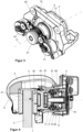
- Fig. 1 shows a braking device according to the invention as a whole, designed as a disc brake.
- This comprises a brake disc 2, which forms a counter-braking part within the meaning of the invention and is connected to a vehicle wheel (not shown here) rotatable about a wheel axis R.
- a brake caliper 3 engages around the two axial end faces of the brake disc 2.
- Brake disc 2 is designed as a non-ventilated brake disc made of solid material. Alternatively, it can also be designed as an internally ventilated brake disc.
- An electric brake actuator 4 according to the invention is attached to the brake calliper 3, which Figure 3 shown in a separate, isolated schematic perspective view, and in the Figures 4 to 7 is explained in detail.
- the brake actuator 4 comprises an adjusting device 5 which extends axially in the direction of an axis A which is parallel to the wheel axis R and indicates the adjustment direction V of the adjusting device 5.
- the brake disc 2 is arranged axially between two brake pads 31 and 32.
- One brake pad 31 is firmly supported on the brake calliper 3 on the side facing away from the brake actuator 4.
- the other brake pad 32 which forms a braking part in the sense of the invention, is attached to the adjusting device 5 and can be adjusted by the latter in the axial adjustment direction V defined by the axis A to generate the braking engagement on the brake disc 2, as shown in Figure 4 indicated by the arrow.
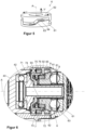
- the structure of the adjusting device 5 is shown in Figure 4 and in the enlarged section in Figure 6 shown.
- the adjusting device 5 comprises a first actuator 6, which has a ball ramp arrangement, also referred to as a ramp bearing, and a second actuator 7, which is axially (with respect to the axis A) serially coupled thereto and has a spindle drive.
- the first actuator 6, which in the example shown is designed as a ball ramp arrangement or ramp bearing, comprises a drive-side cam disc 61 and an output-side cam disc 62 supported axially and rotationally fixed on the brake actuator 4.
- Balls 63 are arranged between the cam discs 61 and 62.
- the cam discs 61 and 62 have axially opposite ramp-like raceways 64, which are inclined to the axis A, between which balls 63 can roll.
- the brake pad 32 can be adjusted as in Figure 4 shown can be brought into braking engagement by actuating the first actuator 6.
- the cam disc 62 is connected to a coaxial gear 65, which is designed as a spur gear and forms a drive wheel in the sense of the invention.
- the gear 65 is in gear engagement with a first electric actuator 41. This enables the rotating drive of the cam disc 62 and thus an actuation of the first actuator 6.
- This internal thread is formed in the output-side cam disc 62 of the first actuator 6, so that the functions of the output-side cam disc 62 and the drive-side spindle nut 72 are combined in one component.
- the threaded spindle 71 is connected via a hub part 74 to a coaxial gear 75, which is axially fixed and rotatably mounted in the brake actuator 4.
- the threaded spindle is coupled to the gear 75 in a torque-locking but axially displaceable manner via drivers 73, which may, for example, have radially projecting projections or teeth that engage axially displaceably in axial slots of the hub part 74.
- gear 75 can be designed as a spur gear and is arranged coaxially adjacent to it. This gear 75 is in gear engagement with a second electric actuator 42. This enables the rotating drive of the threaded spindle 71 and thus the actuation of the second actuator 7.
- the threaded spindle 71 is connected axially via a thrust bearing 43, for example an axial roller bearing as shown, to a pressure piece 44 to which the displaceable brake pad 32 is attached, as in Figure 4 can be seen.
- the pressure piece 44 can also be referred to as a piston.
- the clutch device according to the invention has a friction element 8, which is designed as a coaxial, conical extension directed from the cam disc 62 toward the second actuator 7.
- the conical extension has a conical friction surface 81 arranged externally on an outer cone.
- the friction element 81 can preferably be formed integrally with the cam disc 62/spindle nut 72.
- the friction element 8 is frictionally coupled to a counter friction element 9 in the clutch engagement.
- the conical projection axially engages a corresponding conical opening of the counter friction element 9, which has a conical friction surface 91 arranged in an inner cone.
- the friction surface 81 and the counter friction surface 91 are in frictional contact with each other, as shown in Figure 6 is clearly visible.
- the counter friction element 9 is coupled to the gear 75 in a torque-locking but axially displaceable manner via drivers 92 which engage axially displaceably in corresponding slots 76 in the hub part 74 or the gear 75.
- a spring element 93 is arranged between the gear 75 or the hub part 74 connected thereto and the counter friction element 9. Its axially acting spring force elastically braces the counter friction element 9 against the friction element 8. This generates a defined clutch torque of the friction clutch according to the invention formed by the friction element 8 and the counter friction element 9.
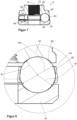
- Figure 7 shows a longitudinal section along the axis A through the actuator 6 according to the invention according to Figures 5 and 6 .
- Figure 8 is an enlarged section of Figure 7 shown in the area of careers 64.
- the ball 63 has a ball diameter Db.
- FIG 10 The two cam discs 61 and 62 are shown separately in perspective, each in a view of the raceways 64.
- Figure 10 The curved arrows indicate the inclination of the raceways 64, which increase in the direction of the arrow relative to the axis A in the circumferential direction.
- Exactly three raceways 64 are arranged evenly distributed around the circumference.
- the three balls 63 rolling therein are also evenly distributed around the circumference and are held in a ball cage 66, allowing free rotation in their relative positions.
- Figure 11 shows an enlarged sectional view BB from Figure 10 through the end regions of the raceway 64 (in the circumferential direction), which projects axially furthest from the cam disk 61 or 62.
- One end region belongs to one raceway 64 and the other end region to the adjacent raceway 64.
- the inclination of the raceway 64 is indicated schematically in a greatly exaggerated manner by the oblique arrow.
- a trough-shaped depression 67 is formed in the raceway 64, which is indicated schematically in the drawing by a downward-pointing arrow.
- a shoulder 68 is provided which is designed to limit the movement of the balls 63, with the shoulder 68 and the depression 67 each forming the flanks 67F, 68F of the elevation 69.
- the ball 63 can engage in this depression 67 when, during adjustment, it reaches the end position in which the cam disks 61 and 62 are moved axially almost as far apart as possible and in the process realizes a stroke h.
- This adjustment position corresponds to the braking engagement.
- the cam discs 61 and 62 are axially moved apart to their maximum extent when the balls 63 are just before moving into the recess 67. This position is marked with H.
- the seat in the recess 67 releasably fixes the ball 63 in order to realize a parking brake position in which the braking force is held stable against the axial restoring force exerted by the brake disc 2 on the brake pad 32. Thanks to this recess 67, it is possible to operate the servo motor 41 with a very low current or even without current in the parking brake position, so that this parking position can be maintained without time restrictions.
- the adjustment drive 6 is not self-locking when the ball 63 is located outside the recess 67 and the shoulder 68 along the track 64. Then, after a braking operation has ended, the cam discs 61 and 62 can be moved axially toward each other again by a relatively low restoring force in order to release the braking engagement.
- the brake is in the service braking position. If the balls 63 are located outside the recess 67 along the track 64 and not in contact with the shoulder 68, the brake is in the service braking position. If the balls 63 are in contact with the shoulder, the brake is in the release position, meaning no braking engagement takes place.
Landscapes
- Engineering & Computer Science (AREA)
- General Engineering & Computer Science (AREA)
- Mechanical Engineering (AREA)
- Transportation (AREA)
- Braking Arrangements (AREA)
Description
- Die Erfindung betrifft eine elektromechanische Bremsvorrichtung für ein Kraftfahrzeug, umfassend eine elektromotorische Stellvorrichtung und ein damit verbundenes Bremsteil, das von der Stellvorrichtung verstellbar und mit einem Gegenbremsteil in Bremseingriff bringbar ist, wobei die Stellvorrichtung mindestens einen Stelltrieb aufweist, wobei der Stelltrieb eine Kugelrampenanordnung umfassend zwei Kurvenscheiben aufweist, wobei die Kurvenscheiben von einem elektrischen Stellmotor um eine Achse relativ zueinander drehend antreibbar sind, und einander axial gegenüberliegende, schräg zu der Achse liegende Laufbahnen aufweisen, zwischen denen jeweils abwälzbar eine Kugel angeordnet ist, wobei die Laufbahnen ein zumindest abschnittweise gerundetes Querschnittsprofil mit einem Laufbahnradius aufweisen, und die Kugel einen Kugeldurchmesser aufweist, wobei zwischen dem Laufbahnradius rg und dem Kugeldurchmesser ein Verhältnis größer als 0,5 ausgebildet ist.
- Eine derartige Bremsvorrichtung eines Kraftfahrzeugs ist als Reibungsbremse ausgebildet, bei dem ein am Fahrgestellt abgestütztes, relativ zur Drehung des zu bremsenden Rades feststehendes Bremsteil mittels einer Stellvorrichtung in Bremseingriff gebracht werden kann mit einem Gegenbremsteil, welches mit dem Rad rotiert. Im Bremseingriff wird ein Reibkontakt zwischen Bremsteil und Gegenbremsteil erzeugt, wobei das durch Reibung erzeugte Bremsmoment umso größer ist, je höher die von der Stellvorrichtung in der Verstellrichtung ausgeübte Verstellkraft ist. Bei der an sich bekannten Bauform als Scheibenbremse umfasst das Bremsteil einen Bremsbelag, und das Gegenbremsteil eine mit dem Rad rotierende Bremsscheibe.
- Die Stellvorrichtung einer gattungsgemäßen Bremsvorrichtung weist mindestens einen elektromotorischen Stelltrieb auf. Ein derartiger Stelltrieb ist ausgebildet, ein von einem elektrischen Motor um eine Achse ausgeübtes Drehmoment in eine axiale Verstell- oder Hubbewegung umzusetzen, durch die das Bremsteil in oder aus dem Bremseingriff gebracht werden kann.
- Im gattungsbildenden Stand der Technik ist es beispielsweise aus der
DE 10 2017 123 266 A1 bekannt, einen Stelltrieb als Kugelrampenanordnung, auch als Rampenlager bezeichnet, auszubilden. Dieser Stelltrieb dient als Betriebsbremse, um im Fahrbetrieb durch manuelle oder automatisierte Betätigung einen Bremseingriff zu erzeugen oder freizugeben. - Die Kugelrampenanordnung weist zwei Kurvenscheiben auf, von denen eine mit einem Antriebsrad verbunden ist. Die Kurvenscheiben weisen gegen die Achse geneigte Laufbahnen oder Rampen auf, zwischen denen in Umfangsrichtung Kugeln abwälzbar angeordnet sind. Eine relative Drehung der Kurvenscheiben durch den elektrischen Stellmotor um eine Achse wird durch die dabei in den Laufbahnen abrollenden Kugeln in eine relative axiale Verlagerung der Kurvenscheiben umgesetzt, die eine Verstellung des damit verbundenen Bremsteils bewirkt.
- Um eine hohe Kraftübersetzung zwischen dem vom Stellmotor eingeleiteten Antriebsmoment und der Verstellung der Kurvenscheiben zu erreichen, so dass das Bremsteil mit einer möglichst hohen Bremskraft in Bremseingriff gebracht werden kann, ist eine relativ flache Neigung der Laufbahnen erforderlich, die auch als Steigung bezeichnet wird. Daraus resultiert eine hohe Hertz'sche Pressung, d.h. eine hohe Flächenpressung, mit der jeweils eine Kugel in ihrer näherungsweise punktförmigen Kontaktfläche gegen die Laufbahnen angedrückt wird. Diese Pressung ist umso höher, je flacher die Neigung ist. Zugleich soll der Stelltrieb beim Lösen der Bremse schnell und sicher wieder in seine Ausgangslage vor dem Bremsvorgang zurück gelangen. Um eine derartige Rückstellung zu ermöglichen, ist eine nicht-selbsthemmende Ausgestaltung des Stelltriebs erforderlich, bei der die beiden Kurvenscheiben durch eine geringe von außen einwirkende axiale Rückstellkraft wieder axial aufeinander zu bewegt werden können. Dabei rollen die Kugeln entgegen der vom Stellmotor zum Bremsen ausgeübten Drehung unter relativer Drehung der Kurvenscheiben wieder in ihre Ausgangslage zurück. Dies setzt voraus, dass die Kugeln möglichst leichtgängig mit geringer Rollreibung in den Laufbahnen rollen können. Die nicht-selbsthemmende Charakteristik könnte zwar prinzipiell durch eine steilere Neigung der Laufbahnen begünstigt werden, wodurch jedoch die Kraftübersetzung inakzeptabel verringert würde. Außerdem muss sichergestellt sein, dass die Laufbahnen auch nach einer Vielzahl von Bremsvorgängen über die gesamte Lebensdauer der Bremse nicht durch die hohen Flächenpressungen beeinträchtigt werden.
- Folglich besteht im Stand der Technik ein Zielkonflikt bezüglich der Realisierung einer hohen Kraftübersetzung und einer nicht-selbsthemmenden Rückstellung.
- Angesichts der vorangehend erläuterten Problematik ist es eine Aufgabe der vorliegenden Erfindung, eine verbesserte Funktion mit einer optimierten Rückstellcharakteristik zu realisieren.
- Diese Aufgabe wird erfindungsgemäß gelöst durch die Bremsvorrichtung mit den Merkmalen des Anspruchs 1. Vorteilhafte Weiterbildungen ergeben sich aus den Unteransprüchen.
- Bei einer elektromechanischen Bremsvorrichtung für ein Kraftfahrzeug, umfassend eine elektromotorische Stellvorrichtung und ein damit verbundenes Bremsteil, das von der Stellvorrichtung verstellbar und mit einem Gegenbremsteil in Bremseingriff bringbar ist, wobei die Stellvorrichtung mindestens einen Stelltrieb aufweist, wobei der Stelltrieb eine Kugelrampenanordnung umfassend zwei Kurvenscheiben aufweist, wobei die Kurvenscheiben von einem elektrischen Stellmotor um eine Achse relativ zueinander drehend antreibbar sind, und
einander axial gegenüberliegende, schräg zu der Achse liegende Laufbahnen aufweisen, zwischen denen jeweils abwälzbar eine Kugel angeordnet ist, wobei die Laufbahnen ein zumindest abschnittweise gerundetes Querschnittsprofil mit einem Laufbahnradius aufweisen, und die Kugel einen Kugeldurchmesser aufweist, wobei zwischen dem Laufbahnradius rg und dem Kugeldurchmesser ein Verhältnis größer als 0,5 ausgebildet ist, ist erfindungsgemäß in einer ersten Ausführung der Erfindung vorgesehen, dass die Laufbahn in mindestens einem Endabschnitt eine Abflachung aufweist. - Für einen gegebenen Laufbahnradius rg und einen Kugeldurchmesser Db gilt für das Verhältnis C: C = rg / Db > 0,5.
- Es wird ein optimiertes Verhältnis zwischen dem Laufbahnradius und dem Kugeldurchmesser vorgegeben, welches es ermöglicht, die den eingangs beschriebenen Zielkonflikt zwischen einer möglichst hohen Kraftübersetzung beim motorischen Antrieb des Stelltriebs und einer nicht-selbsthemmenden Rückstellung zu lösen. Dies erfolgt unter Berücksichtigung der strukturellen und funktionalen Besonderheiten der Kugelrampenanordnung. Diese betreffen insbesondere den Umstand, dass an jeder Kurvenscheibe eine geringe Anzahl von Laufbahnen vorgesehen sind, wobei zwischen zwei paarweise axial gegenüberliegenden Laufbahnen jeweils genau eine Kugel angeordnet ist. Durch die relativ geringe Anzahl der Kugeln, die über ihre Kontaktflächen die gesamte ausgeübte Verstellkraft auf die Laufbahnen übertragen, wird eine entsprechend hohe Hertz'sche Pressung erzeugt. Bei einer Kugelrampenanordnung ist es jedoch funktionsbedingt nicht möglich, wie etwa bei einem gewöhnlichen Wälzlager die Anzahl der Kugeln zwischen zwei Laufbahnen zu erhöhen, um die jeweilige Flächenpressung zu reduzieren. Eine Erhöhung der Anzahl der Laufbahnen zu demselben Zweck wäre ohne Beeinträchtigung der Funktionalität, beispielsweise des axialen Verstellwegs, ist ebenfalls nicht praktikabel.
- Um die Kugelrampenanordnung unter Berücksichtigung der vorgenannten Besonderheiten zu optimieren, hat sich überraschenderweise herausgestellt, dass ein Verhältnis von größer als 0,5, welches eine untere Grenze für den relativen Laufbahnradius definiert, eine akzepabel niedrige Hertz'sche Pressung bei gleichzeitig hinreichend geringer Rollreibung ermöglicht. Dadurch kann der Vorteil einer hohen Belastbarkeit und Verstellkraft bei einer hinreichenden nicht-selbsthemmenden Rückstellung realisiert werden.
- Bevorzugt kann vorgesehen sein, dass das Verhältnis kleiner gleich 0,75 ist. Zwischen dem Laufbahnradius rg und dem Kugeldurchmesser Db wird das Verhältnis C kleiner gleich 0,75 ausgebildet ist, so dass gilt: 0,75 ≥ C = rg / Db > 0,5. Dadurch wird ein oberer Grenzwert definiert. Dabei ist die Hertz'sche Pressung zwar höher, als bei einem Wert von 0,5, vorteilhaft ist jedoch eine verringerte Rollreibung.
- In dem erfindungsgemäßen Bereich des Verhältnisses zwischen 0,5 und 0,75 kann eine qualitative Verbesserung der speziellen Funktionseigenschaften der Kugelrampenanordnung realisiert werden.
- Besonders bevorzugt ist vorgesehen, dass das Verhältnis 0,55 beträgt. Es hat sich herausgestellt, dass dadurch ein spezifisches Optimum einer relativ geringen Hertz'schen Pressung bei relativ niedrigem Rollwiderstand diese Ausführung. Diese Ausgestaltung bietet besondere Vorteile bei einer Dreifach-Kugelrampenanordnung mit drei Kugeln und drei Laufbahnen pro Kurvenscheibe.
- Besonders vorteilhaft ist es, dass eine Kurvenscheibe genau drei Laufbahnen aufweist und genau drei Kugeln vorgesehen sind. Dadurch wird eine sogenannte Dreifach-Kugelrampenanordnung realisiert. Die Laufbahnen und die Kugeln sind dabei vorzugsweise gleichartig ausgebildet und gleichmäßig über den Umfang verteilt angeordnet. Durch die drei Laufbahnen und die drei Kugeln wird eindeutig eine senkrecht zur Achse stehende Ebene definiert, und es wird ein eindeutig bestimmtes Dreipunkt-Lager gebildet. Dies ist für die Verstellung des Bremselements und damit für die sichere Funktion besonders vorteilhaft Die Erfindung ermöglicht insbesondere bei dieser Ausführung eine funktionale Optimierung.
- Eine vorteilhafte Ausführung ist, dass die Laufbahn ein durchgehend kreisrund gebogenes Querschnittsprofil aufweist. Das Querschnittprofil wird durch einen einzigen durchgehenden Kreisbogenabschnitt gebildet, in dem die Kugel die Laufbahn in einer einzigen, näherungsweise punktförmigen Kontaktfläche axial kontaktiert. Das erfindungsgemäße Verhältnis ermöglicht eine optimal reduzierte Flächenpressung bei geringem Rollwiderstand. Von Vorteil ist dabei weiterhin, dass die maximale Materialbeanspruchung so weit begrenzt werden kann, dass bekannte Wälzlagerstähle für die Kurvenscheiben eingesetzt werden können, um eine jederzeit hinreichende Dauerbelastbarkeit und Betriebssicherheit zu gewährleisten.
- Alternativ ist es möglich, dass die Laufbahn ein gotisches Querschnittsprofil aufweist. Ein gotisches Profil weist definitionsgemäß zwei spiegelsymmetrische, spitz zusammenlaufende Kreisbogensegmente auf, welche die gegenüberliegenden Seitenflanken der Laufbahn bilden. Die Kreisbogensegmente können jeweils einen erfindungsgemäßen Laufbahnradius aufweisen. Die Kugel kontaktiert jede der beiden Kreisbogensegmente jeweils in einer axial versetzten Kontaktfläche. Mit andern Worten kontaktiert die Kugel die beiden Laufbahnen in insgesamt vier Kotaktflächen. Dadurch kann die Hertz'sche Pressung und die Rollreibung reduziert werden.
- Es ist möglich, dass die Laufbahn einen linearen oder nichtlinearen Verlauf der Neigung aufweist. Durch einen im Wesentlichen linearen Verlauf kann eine gleichmäßige Kraftübertragung über den gesamten Verstellweg realisiert werden. Ein nichtlinearer Verlauf, der über die Erstreckung einer Laufbahn in Umfangsrichtung beispielsweise bogenförmig oder S-förmig ausgebildet sein kann, ist abhängig von der jeweiligen Winkelstellung der Kurvenscheiben ein nichtlinearer Verlauf der Kraftübertragung realisierbar. Beispielsweise kann durch eine steilere Neigung am Anfang oder im mittleren Bereich der Laufbahn bei gleichbleibender Drehzahl des motorischen Antriebs eine schnellere Verstellung erreicht werden, und durch eine flachere Neigung im Endbereich, kurz bevor das Bremselement in den reibschlüssigen Bremseingriff gelangt, eine höhere Verstellkraft, die für eine erhöhte Bremswirkung sorgt.
- Erfindungsgemäß ist vorgesehen, dass die Laufbahn in mindestens einem Endabschnitt eine Abflachung aufweist. Die Laufbahn erstreckt sich in Umfangsrichtung über eine definierte Länge, die zwischen ihren umfangsseitigen Enden den Wälz- oder Abrollweg der Kugel begrenzt. Zwischen den Enden weist die Laufbahn eine definierte Neigung auf, die auch als Steigung bezeichnet werden kann. Ein Endabschnitt wird durch einen Abschnitt am Ende des möglichen Abrollwegs gebildet, der in Umfangsrichtung gemessen bevorzugt mindestens einem Kugelradius entspricht. Im Bereich der Abflachung ist die Neigung der Laufbahn gegenüber der Achse, relativ zu einem an den Endabschnitt anschließenden Rollabschnitt reduziert. Es kann beispielsweise eine Neigung von null ausgebildet sein, wobei die Laufbahn senkrecht zur Achse verläuft. Entsprechend kann die Kugel gegenüber von außen auf den Stelltrieb axial einwirkenden Rückstellkräften selbsthemmend fixiert sein. Dadurch kann die Funktion einer Feststell- oder Parkbremse realisiert sein.
- Eine vorteilhafte Weiterbildung kann vorsehen, dass die Laufbahn in mindestens einem Endabschnitt eine muldenförmige Vertiefung aufweist. Die Vertiefung ist in einem Endbereich, auch als Endabschnitt bezeichnet, der Laufbahn angeordnet, in dem der Bremseingriff erzeugt wird. Im Bereich der Vertiefung ist die Neigung abschnittweise der Neigung zwischen den Endabschnitten entgegengesetzt. Die Vertiefung kann bevorzugt bogenförmig gerundet sein. Vorzugsweise kann sie, in Umfangsrichtung gemessen, um mindestens einen Kugelradius vom Ende der Laufbahn beabstandet sein. Die Kugel kann beim Erreichen des Bremseingriffs in die Vertiefung rollen und eine in Umfangsrichtung stabile Rastposition einnehmen. In der Rastposition ist die Kugel unabhängig von der auf die Kurvenscheiben einwirkenden axialen Rückstellkraft gehalten. Dadurch kann eine definierte, selbsthaltende Feststell-Bremsposition der Kugelrampenanordnung realisiert werden.
- Eine vorteilhafte Weiterbildung kann vorsehen, dass die Laufbahn in mindestens einem Endabschnitt eine Schulter aufweist. Wenn die Kugeln an der Schulter des Endabschnitts anliegen, ist die Bremse in der Freigabestellung, sprich es findet kein Bremseingriff statt. Die Schulter begrenzt die Laufbahn in Umfangsrichtung.
- Bevorzugt weist eine Laufbahn einen ersten Endabschnitt auf, in dem die Vertiefung ausgebildet ist, und einen zweiten Endabschnitt, in dem die Schulter ausgebildet ist. In einer weiteren vorteilhaften Weiterbildung bildet die Schulter einer ersten Laufbahn und die Vertiefung einer zweiten Laufbahn jeweils eine Flanke einer Erhebung. Die Erhebung bildet in Umfangsrichtung die Grenze zwischen der einen Laufbahn und der anderen Laufbahn, beispielsweise zwischen einer ersten Laufbahn und einer zweiten Laufbahn, und ist in Umfangsrichtung zwischen den Laufbahnen angeordnet.
- Es kann bevorzugt vorgesehen sein, dass die Stellvorrichtung mindestens zwei seriell gekoppelte Stelltriebe aufweist. Ein erster und ein zweiter Stelltrieb sind dabei bezüglich ihrer Verstellwege axial in Reihe angeordnet. Der bevorzugt koaxial zum ersten Stelltrieb angeordnete zweite Stelltrieb vorzugsweise ist ebenfalls ausgebildet, um eine Drehung des Antriebselements in eine axiale Verstellung des Bremsteils umzusetzen. Durch einen ersten Stelltrieb, der gemäß der Erfindung ausgebildet sein kann, kann eine Betriebsbremse realisiert sein. Ein daran seriell angekoppelter zweiter Stelltrieb kann beispielsweise zur Justierung des Luftspalts zwischen dem Brems- und Gegenbremselement vorgesehen sein.
- Es ist vorteilhaft, dass die seriell gekoppelten Stelltriebe koaxial angeordnet sind. Dabei kann jeder Stelltrieb ein um die Achse drehend antreibbares Antriebsrad aufweisen, welche in Getriebeeingriff mit einem Stellmotor stehen kann. Bei der erfindungsgemäßen Ausführung kann ein Antriebsrad, beispielsweise ein Zahnrad, drehfest mit einer antriebsseitigen Kurvenscheibe verbunden sein.
- In der vorgenannten Ausführung kann es vorteilhaft sein, dass einer der Stelltriebe eine Kugelrampenanordnung aufweist, und ein anderer Stelltrieb eine nach einem anderen Wirkprinzip arbeitende Verstelleinrichtung. Beispielsweise kann der zweite Stelltrieb einen Spindeltrieb aufweisen, bei dem das Antriebselement eine drehend antreibbare Spindelmutter aufweist, und das Abtriebselement eine darin eingreifende, relativ dazu axial verlagerbare Gewindespindel, oder umgekehrt. Es können auch andere Bauformen von Stelltrieben eingesetzt werden, die beispielsweise Nocken- oder Kurvenscheiben, Kippstiftanordnungen oder dergleichen umfassen können, und bevorzugt ebenfalls eine motorische Drehung eines Antriebselements in eine lineare Verstellung des Abtriebselements umsetzen.
- In einer vorteilhaften Weiterbildung kann es vorgesehen sein, dass zumindest einer der Kurvenscheiben als Sinterbauteil oder als Kaltfliesspressteil ausgebildet ist. Sinterbauteile werden aus pulverförmigen Materialien hergestellt, wobei das Material durch Druck und Erhitzung zu einem festen Körper verbunden wird. Dadurch lassen sich komplizierte Konturen rationell und mit hoher Maßhaltigkeit herstellen. Außerdem können vorteilhafte Materialeigenschaften realisiert werden, beispielsweise eine hohe Härte und damit eine hohe Verschleißfestigkeit.
- Vorteilhafte Ausführungsformen der Erfindung werden im Folgenden anhand der Zeichnungen näher erläutert. Im Einzelnen zeigen:
- Figur 1
- eine erfindungsgemäße Bremsvorrichtung in einer schematischen perspektivischen Ansicht,
- Figur 2
- eine seitliche Ansicht der Bremsvorrichtung gemäß
Figur 1 , - Figur 3
- die erfindungsgemäße Stellvorrichtung der Bremsvorrichtung gemäß
Figur 1 freigestellt in einer schematischen perspektivischen Ansicht, - Figur 4
- einen Schnitt Q-Q durch die Bremsvorrichtung gemäß
Figur 1 , - Figur 5
- den ersten Stelltrieb der Bremsvorrichtung gemäß
Figur 1 freigestellt in einer schematischen perspektivischen Darstellung, - Figur 6
- eine vergrößerte Detailansicht der Stellvorrichtung aus
Figur 4 , - Figur 7
- einen Längsschnitt durch einen erfindungsgemäßen Stelltrieb gemäß
Figur 5 , - Figur 8
- einen vergrößerten Ausschnitt aus
Figur 7 , - Figur 9
- eine schematisch axial auseinander gezogene Darstellung des Stelltriebs gemäß
Figuren 7 bis 8 , - Figur 10
- freigestellte perspektivische Darstellungen der Kurvenscheiben des Stelltriebs gemäß
Figuren 7 bis 9 , - Figur 11
- eine vergrößerte Darstellung des Schnitts B-B aus
Figur 10 . - In den verschiedenen Figuren sind gleiche Teile stets mit den gleichen Bezugszeichen versehen und werden daher in der Regel auch jeweils nur einmal benannt bzw. erwähnt.
-
Fig. 1 zeigt eine erfindungsgemäße Bremsvorrichtung als Ganzes, die als Scheibenbremse ausgebildet ist. Diese umfasst eine Bremsscheibe 2, die ein Gegenbremsteil im Sinne der Erfindung bildet und mit einem hier nicht dargestellten, um eine Radachse R rotierbaren Fahrzeugrad verbunden ist. Ein Bremssattel 3 umgreift die beiden axialen Stirnflächen der Bremsscheibe 2. - Die Bremsscheibe 2 ist hier als unbelüftete Bremscheibe aus Vollmaterial ausgebildet. Alternativ kann diese auch als innenbelüftete Bremsscheibe ausgebildet sein.
- An dem Bremssattel 3 ist ein erfindungsgemäßer elektrischer Bremsaktuator 4 angebracht, die in
Figur 3 in einer separaten, freigestellten schematischen perspektivischen Ansicht gezeigt ist, und in denFiguren 4 bis 7 im Detail erläutert wird. - Der Bremsaktuator 4 umfasst eine Stellvorrichtung 5 die sich axial in Richtung einer Achse A erstreckt, welche parallel zur Radachse R liegt und die Verstellrichtung V der Stellvorrichtung 5 angibt.
- Wie in der Schnittdarstellung von
Figur 4 längs der Achse A erkennbar ist, ist die Bremsscheibe 2 axial zwischen zwei Bremsbelägen 31 und 32 angeordnet. Der eine Bremsbelag 31 ist auf der dem Bremsaktuator 4 abgewandten Seite fest an dem Bremssattel 3 abgestützt. Der andere Bremsbelag 32, der ein Bremsteil im Sinne der Erfindung bildet, ist an der Stellvorrichtung 5 angebracht und von dieser in der durch die Achse A gegebenen, axialen Verstellrichtung V zur Erzeugung des Bremseingriffs auf die Bremsscheibe 2 zu verstellbar, wie inFigur 4 mit dem Pfeil angedeutet ist. - Im unbetätigten Zustand der Bremsvorrichtung 1 befindet sich zwischen der Bremsscheibe 2 und dem verstellbaren Bremsbelag 32 ein axialer Luftspalt L, der in
Figur 4 schematisch übertrieben breit eingezeichnet ist. - Der Aufbau der Stellvorrichtung 5 ist in
Figur 4 und in dem vergrößerten Ausschnitt daraus inFigur 6 dargestellt. - Die Stellvorrichtung 5 umfasst einen ersten Stelltrieb 6, der eine Kugelrampenanordnung, auch als Rampenlager bezeichnet, aufweist, und einen damit axial (bezüglich der Achse A) seriell gekoppelten zweiten Stelltrieb 7, der einen Spindeltrieb aufweist.
- Der erste Stelltrieb 6, der im gezeigten Beispiel als Kugelrampenanordnung bzw. Rampenlager ausgebildet ist, umfasst eine axial und drehfest an dem Bremsaktuator 4 abgestützte, antriebseitige Kurvenscheibe 61 und eine abtriebsseitige Kurvenscheibe 62. Zwischen den Kurvenscheiben 61 und 62 sind Kugeln 63 angeordnet. Wie in der schematisch freigestellten Ansicht von
Figur 5 erkennbar ist, weisen die Kurvenscheiben 61 und 62 einander axial gegenüberliegende rampenartige, schräg zur Achse A liegende Laufbahnen 64 auf, zwischen denen Kugeln 63 abwälzbar sind. Eine Drehung der abtriebsseitigen Kurvenscheibe 62, inFigur 5 oben, relativ zu der feststehenden antriebsseitigen Kurvenscheibe 61 - wie schematisch mit den gebogenen Pfeilen angedeutet - führt zu einer linearen Verstellung der abtriebsseitigen Kurvenscheibe 62 in der Verstellrichtung V parallel zur Achse A. Dadurch kann der Bremsbelag 32 wie inFigur 4 eingezeichnet durch Betätigung des ersten Stelltriebs 6 in Bremseingriff gebracht werden. - Die Kurvenscheibe 62 ist mit einem koaxialen Zahnrad 65 verbunden, welches als Stirnrad ausgebildet ist und ein Antriebsrad im Sinne der Erfindung bildet.
- Das Zahnrad 65 steht im Getriebeeingriff mit einem ersten elektrischen Stellmotor 41. Dieser ermöglicht den drehenden Antrieb der Kurvenscheibe 62 und damit eine Betätigung des ersten Stelltriebs 6.
- Der zweite Stelltrieb 7, der im gezeigten Beispiel als Spindeltrieb ausgebildet ist, weist abtriebsseitig eine Gewindespindel 71 auf, die in das Innengewinde einer antriebsseitigen Spindelmutter 72 eingreift. Dieses Innengewinde ist in der abtriebsseitigen Kurvenscheibe 62 des ersten Stelltriebs 6 ausgebildet, so dass das die Funktionen der abtriebsseitigen Kurvenscheibe 62 und der antriebsseitigen Spindelmutter 72 in einem Bauelement vereinigt sind.
- Die Gewindespindel 71 ist über ein Nabenteil 74 mit einem koaxialen Zahnrad 75 verbunden, welches axial fixiert in dem Bremsaktuator 4 drehbar gelagert ist. Über Mitnehmer 73, die beispielsweise radial vorstehende Vorsprünge oder Zähne aufweisen können, die in axiale Schlitze des Nabenteils 74 axial verschieblich eingreifen, ist die Gewindespindel drehmomentschlüssig, aber axial verlagerbar mit dem Zahnrad 75 gekuppelt.
- Das Zahnrad 75 kann wie das Zahnrad 65 als Stirnrad ausgeführt sein und ist zu diesem benachbart koaxial angeordnet. Dieses Zahnrad 75 steht im Getriebeeingriff mit einem zweiten elektrischen Stellmotor 42. Dieser ermöglicht den drehenden Antrieb der Gewindespindel 71 und damit eine Betätigung des zweiten Stelltriebs 7.
- Die Gewindespindel 71 ist über ein Drucklager 43, beispielsweise wie dargestellt ein Axialwälzlager, axial mit einem Druckstück 44 verbunden, an dem der verlagerbare Bremsbelag 32 angebracht ist, wie in
Figur 4 erkennbar ist. Das Druckstück 44 kann auch als Kolben bezeichnet werden. - Die erfindungsgemäße Kupplungsvorrichtung weist ein Reibelement 8 auf, welches als koaxialer, konischer Ansatz von der Kurvenscheibe 62 auf den zweiten Stelltrieb 7 zu gerichtet ist. Der konische Ansatz weist eine außen auf einem Außenkonus angeordnete konische Reibfläche 81 auf. Das Reibelement 81 kann bevorzugt einstückig mit der Kurvenscheibe 62 / Spindelmutter 72 ausgebildet sein.
- Das Reibelement 8 ist im Kupplungseingriff reibschlüssig mit einem Gegenreibelement 9 gekuppelt. Dabei taucht der konische Ansatz axial in eine korrespondierende konische Öffnung des Gegenreibelements 9 ein, welche eine in einem Innenkonus angeordnete konische Reibfläche 91 aufweist. Im Kupplungseingriff liegen die Reibfläche 81 und die Gegenreibfläche 91 reibschlüssig gegeneinander an, wie in
Figur 6 deutlich erkennbar ist. - Das Gegenreibelement 9 ist über Mitnehmer 92, die in korrespondierende Schlitze 76 in dem Nabenteil 74 oder dem Zahnrad 75 axial verschiebbar eingreifen, drehmomentschlüssig, aber axial verlagerbar mit dem Zahnrad 75 gekuppelt.
- Zwischen dem Zahnrad 75 oder dem damit verbundenen Nabenteil 74 und dem Gegenreibelement 9 ist ein Federelement 93 angeordnet. Durch dessen axial wirksame Federkraft wird das Gegenreibelement 9 gegen das Reibelement 8 elastisch verspannt. Dadurch wird ein definiertes Kupplungsmoment der durch das Reibelement 8 und das Gegenreibelement 9 gebildeten erfindungsgemäßen Reibkupplung erzeugt.
-
Figur 7 zeigt einen Längsschnitt entlang der Achse A durch den erfindungsgemäßen Stellantrieb 6 gemäßFiguren 5 und 6 . InFigur 8 ist ein vergrößerter Ausschnitt ausFigur 7 im Bereich der Laufbahnen 64 dargestellt. - Die Kugel 63 hat einen Kugeldurchmesser Db.
- Die Laufbahnen 64 weisen im gezeigten Beispiel ein durchgehend kreisrund gebogenes Querschnittsprofil auf, das einen Laufbahnradius rg aufweist.
- Erfindungsgemäß gilt für das Verhältnis C = rg / Db : C > 0,5,
- und bevorzugt: 0,75 ≥ C = rg / Db > 0,5.
- In
Figur 10 sind die beiden Kurvenscheiben 61 und 62 separat perspektivisch dargestellt, jeweils in einer Ansicht auf die Laufbahnen 64. Dabei ist inFigur 10 mit den gebogenen Pfeilen die Neigung der Laufbahnen 64 angedeutet, wobei diese in Pfeilrichtung relativ zur Achse A in Umfangsrichtung ansteigen. - Jeweils genau drei Laufbahnen 64 sind gleichmäßig über den Umfang verteilt angeordnet. Die darin abrollbaren drei Kugeln 63 sind ebenfalls über den Umfang gleichmäßig verteilt, und werden in ihrer relativen Position frei rotierbar in einem Kugelkäfig 66 gehalten.
-
Figur 11 zeigt eine vergrößerte Schnittansicht B-B ausFigur 10 durch die Endbereiche der Laufbahn 64 (in Umfangsrichtung), der am weitesten von der Kurvenscheibe 61 bzw. 62 axial vorsteht. Dabei gehört der eine Endbereich zu der einen Laufbahn 64 und der andere Endbereich zu der benachbarten Laufbahn 64. Die Neigung der Laufbahn 64 ist schematisch stark übertrieben mit dem schräggestellten Pfeil angedeutet. In dem ersten Endbereich ist jeweils eine muldenförmige Vertiefung 67 in die Laufbahn 64 eingeformt, die in der Zeichnung schematisch mit einem nach unten gerichteten Pfeil angedeutet ist. In dem zweiten Endbereich ist eine zur Laufbegrenzung der Kugeln 63 ausgebildete Schulter 68 vorgesehen, wobei Schulter 68 und Vertiefung 67 jeweils die Flanken 67F, 68F der Erhebung 69 bilden. In diese Vertiefung 67 kann die Kugel 63 einrasten, wenn sie beim Verstellen die Endposition erreicht, in der die Kurvenscheiben 61 und 62 axial nahezu maximal auseinander bewegt sind und dabei einen Hub h realisiert. Diese Verstellposition entspricht dem Bremseingriff. Die Kurvenscheiben 61 und 62 sind axial maximal auseinander bewegt, wenn sich die Kugeln 63 kurz vor dem Hineinbewegen in die Vertiefung 67 befinden. Diese Position ist mit H gekennzeichnet. Durch den Sitz in der Vertiefung 67 wird die Kugel 63 lösbar fixiert, um eine Feststell- oder Parkbremsstellung zu realisieren, in der die Bremskraft entgegen der von der Bremsscheibe 2 auf den Bremsbelag 32 ausgeübten axialen Rückstellkraft stabil gehalten wird. Dank dieser Vertiefung 67 ist es in der Festellbremsposition möglich, den Stellmotor 41 mit einem sehr geringen Strom oder sogar ohne Bestromung zu betreiben, so dass diese Parkposition ohne zeitliche Beschränkung gehalten werden kann. Im Unterschied dazu ist der Verstelltrieb 6 nicht-selbsthemmend, wenn sich die Kugel 63 im Verlauf der Laufbahn 64 außerhalb der Vertiefung 67 und der Schulter 68 befindet. Dann können die Kurvenscheiben 61 und 62 nach Beendigung eines Bremsvorgangs bereits durch eine relativ geringe Rückstellkraft wieder axial aufeinander zu bewegt werden, um den Bremseingriff zu lösen. Wenn sich die Kugeln 63 im Verlauf der Laufbahn 64 außerhalb der Vertiefung 67 und nicht in Anlage an der Schulter 68 befinden, dann ist die Bremse in der Betriebsbremsstellung. Wenn die Kugeln 63 an der Schulter anliegen, ist die Bremse in der Freigabestellung, sprich es findet kein Bremseingriff statt. -
- 1
- Bremsvorrichtung
- 2
- Bremsscheibe
- 3
- Bremssattel
- 31, 32
- Bremsbelag
- 4
- Bremsaktuator
- 41, 42
- Stellmotor
- 43
- Drucklager
- 44
- Druckstück
- 5
- Stellvorrichtung
- 6
- erster Stelltrieb
- 61
- Kurvenscheibe
- 62
- Kurvenscheibe (integriert mit Spindelmutter 72)
- 63
- Kugel
- 64
- Laufbahn
- 65
- Zahnrad
- 66
- Kugelkäfig
- 67
- Vertiefung
- 7
- zweiter Stelltrieb
- 71
- Gewindespindel
- 72
- Spindelmutter (integriert mit Kurvenscheibe 62)
- 73
- Mitnehmer
- 74
- Nabenteil
- 75
- Zahnrad
- 76
- Schlitz
- 8
- Reibelement
- 81
- Reibfläche
- 9
- Gegenreibelement
- 91
- Gegenreibfläche
- 92
- Mitnehmer
- 93
- Federelement
- A
- Achse
- R
- Radachse
- V
- Verstellrichtung
- L
- Luftspalt
- Db
- Kugeldurchmesser
- rg
- Laufbahnradius
Claims (11)
- Elektromechanische Bremsvorrichtung (1) für ein Kraftfahrzeug, umfassend eine elektromotorische Stellvorrichtung (5) und ein damit verbundenes Bremsteil (32), das von der Stellvorrichtung (5) verstellbar und mit einem Gegenbremsteil (2) in Bremseingriff bringbar ist,wobei die Stellvorrichtung (5) mindestens einen Stelltrieb (6, 7) aufweist,wobei der Stelltrieb (6) eine Kugelrampenanordnung (6) umfassend zwei Kurvenscheiben (61, 62) aufweist,wobei die Kurvenscheiben (61, 62) von einem elektrischen Stellmotor (41, 42) um eine Achse (A) relativ zueinander drehend antreibbar sind, undeinander axial gegenüberliegende, schräg zu der Achse (A) liegende Laufbahnen (64) aufweisen, zwischen denen jeweils abwälzbar eine Kugel (63) angeordnet ist,wobei die Laufbahnen (64) ein zumindest abschnittweise gerundetes Querschnittsprofil mit einem Laufbahnradius (rg) aufweisen, und die Kugel (63) einen Kugeldurchmesser (Db) aufweist, wobei zwischen dem Laufbahnradius (rg) und dem Kugeldurchmesser (Db) ein Verhältnis (C) größer als 0,5 ausgebildet istdadurch gekennzeichnet,dass die Laufbahn (64) in mindestens einem Endabschnitt eine Abflachung aufweist.
- Bremsvorrichtung nach Anspruch 1, dadurch gekennzeichnet, dass das Verhältnis (C) kleiner gleich 0,75 ist.
- Bremsvorrichtung nach einem der vorangehenden Ansprüche, dadurch gekennzeichnet, dass das Verhältnis (C) 0,55 beträgt.
- Bremsvorrichtung nach einem der vorangehenden Ansprüche, dadurch gekennzeichnet, dass die Laufbahn (64) ein durchgehend kreisrund gebogenes Querschnittsprofil aufweist.
- Bremsvorrichtung nach einem der vorangehenden Ansprüche, dadurch gekennzeichnet, dass die Laufbahn (64) ein gotisches Querschnittsprofil aufweist.
- Bremsvorrichtung nach einem der vorangehenden Ansprüche, dadurch gekennzeichnet, dass die Laufbahn (64) einen linearen oder nichtlinearen Verlauf der Neigung aufweist.
- Bremsvorrichtung nach einem der vorangehenden Ansprüche, dadurch gekennzeichnet, dass eine Kurvenscheibe (61, 62) genau drei Laufbahnen (64) aufweist und genau drei Kugeln (63) vorgesehen sind.
- Bremsvorrichtung nach einem der vorangehenden Ansprüche, dadurch gekennzeichnet, dass die Laufbahn (64) in mindestens einem Endabschnitt eine muldenförmige Vertiefung (67) aufweist.
- Bremsvorrichtung nach einem der vorangehenden Ansprüche, dadurch gekennzeichnet, dass die Stellvorrichtung mindestens zwei seriell gekoppelte Stelltriebe (6, 7) aufweist.
- Bremsvorrichtung nach Anspruch 9, dadurch gekennzeichnet, dass einer der Stelltriebe (6) eine Kugelrampenanordnung aufweist, und ein anderer Stelltrieb (7) eine nach einem anderen Wirkprinzip arbeitende Verstelleinrichtung.
- Bremsvorrichtung nach einem der vorangehenden Ansprüche, dadurch gekennzeichnet, dass zumindest einer der Kurvenscheiben (61, 62) als Sinterbauteil oder als Kaltfliesspressteil ausgebildet ist.
Applications Claiming Priority (2)
| Application Number | Priority Date | Filing Date | Title |
|---|---|---|---|
| BE20235070A BE1031313A9 (de) | 2023-02-01 | 2023-02-01 | Elektromechanische Bremsvorrichtung für ein Kraftfahrzeug |
| PCT/EP2023/079638 WO2024047260A1 (de) | 2023-02-01 | 2023-10-24 | Elektromechanische bremsvorrichtung für ein kraftfahrzeug |
Publications (2)
| Publication Number | Publication Date |
|---|---|
| EP4359273A1 EP4359273A1 (de) | 2024-05-01 |
| EP4359273B1 true EP4359273B1 (de) | 2025-06-04 |
Family
ID=85321188
Family Applications (1)
| Application Number | Title | Priority Date | Filing Date |
|---|---|---|---|
| EP23793889.9A Active EP4359273B1 (de) | 2023-02-01 | 2023-10-24 | Elektromechanische bremsvorrichtung für ein kraftfahrzeug |
Country Status (4)
| Country | Link |
|---|---|
| EP (1) | EP4359273B1 (de) |
| CN (1) | CN120603740A (de) |
| BE (1) | BE1031313A9 (de) |
| WO (1) | WO2024047260A1 (de) |
Family Cites Families (2)
| Publication number | Priority date | Publication date | Assignee | Title |
|---|---|---|---|---|
| JP6137805B2 (ja) * | 2012-07-26 | 2017-05-31 | 曙ブレーキ工業株式会社 | 電動式ディスクブレーキ装置 |
| DE102017123266A1 (de) | 2017-10-06 | 2019-04-11 | Thyssenkrupp Ag | Mechanische Bremsvorrichtung |
-
2023
- 2023-02-01 BE BE20235070A patent/BE1031313A9/de active IP Right Grant
- 2023-10-24 EP EP23793889.9A patent/EP4359273B1/de active Active
- 2023-10-24 CN CN202380092827.7A patent/CN120603740A/zh active Pending
- 2023-10-24 WO PCT/EP2023/079638 patent/WO2024047260A1/de not_active Ceased
Also Published As
| Publication number | Publication date |
|---|---|
| EP4359273A1 (de) | 2024-05-01 |
| BE1031313A1 (de) | 2024-08-27 |
| WO2024047260A1 (de) | 2024-03-07 |
| BE1031313A9 (de) | 2024-09-09 |
| CN120603740A (zh) | 2025-09-05 |
| BE1031313B1 (de) | 2024-09-04 |
Similar Documents
| Publication | Publication Date | Title |
|---|---|---|
| EP0340451B1 (de) | Ausgleichsgetriebe | |
| DE3815225C2 (de) | ||
| EP2222977B1 (de) | Elektromechanische reibungsbremse | |
| EP3417183B1 (de) | Kugelgelenk | |
| EP0368140B1 (de) | Verfahren zum Verstellen von Reibungskupplungen oder -bremsen | |
| DD294764A5 (de) | Ausgleichsgetriebe | |
| DE102005030617A1 (de) | Scheibenbremse in selbstverstärkender Bauart und Ansteuerverfahren für eine selbstverstärkende Bremse | |
| WO1992001884A1 (de) | Armatur zum absperren einer strömung | |
| EP4359273B1 (de) | Elektromechanische bremsvorrichtung für ein kraftfahrzeug | |
| DE102009054879A1 (de) | Axialverstelleinrichtung, beispielsweise für eine Kupplung eines Getriebes oder eine Differentialsperre eines Kraftfahrzeuges | |
| EP1506358A1 (de) | Automatgetriebe mit wenigstens zwei kegelscheibensätzen | |
| DE112004001257T5 (de) | Elektromechanischer Linearaktuator für eine Betriebsbremse eines Kraftfahrzeugs | |
| BE1032041B1 (de) | Verfahren zur Aktivierung einer Parkbremse bei einem Kraftfahrzeug und Kraftfahrzeug mit einer elektromechanischen Bremsvorrichtung | |
| EP4359684B1 (de) | Elektromechanische bremsvorrichtung für ein kraftfahrzeug | |
| DE10234371B4 (de) | Blockierbare Feststellvorrichtung | |
| EP4359683B1 (de) | Elektromechanische bremsvorrichtung für ein kraftfahrzeug und verfahren zum betrieb einer elektromechanischen bremsvorrichtung | |
| EP4374085B1 (de) | Elektromechanische bremsvorrichtung für ein kraftfahrzeug | |
| DE102016214711A1 (de) | Doppelschlingfeder, Rotationseinrichtung und zu aktuierendes System | |
| DE4135739A1 (de) | Selbstsperrendes ausgleichgetriebe mit einer axialspieleinstellung fuer seine reibflaechenpakete | |
| DE102006029944A1 (de) | Selbstverstärkende Scheibenbremse und Verfahren zu deren Ansteuerung | |
| DE102024130823A1 (de) | Kraftfahrzeugtrommelbremse | |
| DE102022213613A1 (de) | Bremseinrichtung | |
| WO2026041348A1 (de) | Trommelbremse, insbesondere für ein nutzfahrzeug | |
| DE202004017716U1 (de) | Aktor zum Erzeugen einer rotatorischen Stellbewegung mit kleinem Drehwinkel | |
| DE102013222031A1 (de) | Einstellvorrichtung zum Schließen eines Luftspalts einer Bremse |
Legal Events
| Date | Code | Title | Description |
|---|---|---|---|
| STAA | Information on the status of an ep patent application or granted ep patent |
Free format text: STATUS: UNKNOWN |
|
| STAA | Information on the status of an ep patent application or granted ep patent |
Free format text: STATUS: THE INTERNATIONAL PUBLICATION HAS BEEN MADE |
|
| PUAI | Public reference made under article 153(3) epc to a published international application that has entered the european phase |
Free format text: ORIGINAL CODE: 0009012 |
|
| STAA | Information on the status of an ep patent application or granted ep patent |
Free format text: STATUS: REQUEST FOR EXAMINATION WAS MADE |
|
| 17P | Request for examination filed |
Effective date: 20240124 |
|
| AK | Designated contracting states |
Kind code of ref document: A1 Designated state(s): AL AT BE BG CH CY CZ DE DK EE ES FI FR GB GR HR HU IE IS IT LI LT LU LV MC ME MK MT NL NO PL PT RO RS SE SI SK SM TR |
|
| STAA | Information on the status of an ep patent application or granted ep patent |
Free format text: STATUS: EXAMINATION IS IN PROGRESS |
|
| 17Q | First examination report despatched |
Effective date: 20240920 |
|
| GRAP | Despatch of communication of intention to grant a patent |
Free format text: ORIGINAL CODE: EPIDOSNIGR1 |
|
| STAA | Information on the status of an ep patent application or granted ep patent |
Free format text: STATUS: GRANT OF PATENT IS INTENDED |
|
| DAV | Request for validation of the european patent (deleted) | ||
| DAX | Request for extension of the european patent (deleted) | ||
| INTG | Intention to grant announced |
Effective date: 20250123 |
|
| GRAS | Grant fee paid |
Free format text: ORIGINAL CODE: EPIDOSNIGR3 |
|
| GRAA | (expected) grant |
Free format text: ORIGINAL CODE: 0009210 |
|
| STAA | Information on the status of an ep patent application or granted ep patent |
Free format text: STATUS: THE PATENT HAS BEEN GRANTED |
|
| AK | Designated contracting states |
Kind code of ref document: B1 Designated state(s): AL AT BE BG CH CY CZ DE DK EE ES FI FR GB GR HR HU IE IS IT LI LT LU LV MC ME MK MT NL NO PL PT RO RS SE SI SK SM TR |
|
| REG | Reference to a national code |
Ref country code: GB Ref legal event code: FG4D Free format text: NOT ENGLISH |
|
| REG | Reference to a national code |
Ref country code: CH Ref legal event code: EP |
|
| REG | Reference to a national code |
Ref country code: DE Ref legal event code: R096 Ref document number: 502023001105 Country of ref document: DE |
|
| REG | Reference to a national code |
Ref country code: IE Ref legal event code: FG4D Free format text: LANGUAGE OF EP DOCUMENT: GERMAN |
|
| REG | Reference to a national code |
Ref country code: NL Ref legal event code: MP Effective date: 20250604 |
|
| PG25 | Lapsed in a contracting state [announced via postgrant information from national office to epo] |
Ref country code: FI Free format text: LAPSE BECAUSE OF FAILURE TO SUBMIT A TRANSLATION OF THE DESCRIPTION OR TO PAY THE FEE WITHIN THE PRESCRIBED TIME-LIMIT Effective date: 20250604 Ref country code: ES Free format text: LAPSE BECAUSE OF FAILURE TO SUBMIT A TRANSLATION OF THE DESCRIPTION OR TO PAY THE FEE WITHIN THE PRESCRIBED TIME-LIMIT Effective date: 20250604 |
|
| REG | Reference to a national code |
Ref country code: LT Ref legal event code: MG9D |
|
| PG25 | Lapsed in a contracting state [announced via postgrant information from national office to epo] |
Ref country code: GR Free format text: LAPSE BECAUSE OF FAILURE TO SUBMIT A TRANSLATION OF THE DESCRIPTION OR TO PAY THE FEE WITHIN THE PRESCRIBED TIME-LIMIT Effective date: 20250905 Ref country code: NO Free format text: LAPSE BECAUSE OF FAILURE TO SUBMIT A TRANSLATION OF THE DESCRIPTION OR TO PAY THE FEE WITHIN THE PRESCRIBED TIME-LIMIT Effective date: 20250904 |
|
| PG25 | Lapsed in a contracting state [announced via postgrant information from national office to epo] |
Ref country code: PL Free format text: LAPSE BECAUSE OF FAILURE TO SUBMIT A TRANSLATION OF THE DESCRIPTION OR TO PAY THE FEE WITHIN THE PRESCRIBED TIME-LIMIT Effective date: 20250604 |
|
| PG25 | Lapsed in a contracting state [announced via postgrant information from national office to epo] |
Ref country code: BG Free format text: LAPSE BECAUSE OF FAILURE TO SUBMIT A TRANSLATION OF THE DESCRIPTION OR TO PAY THE FEE WITHIN THE PRESCRIBED TIME-LIMIT Effective date: 20250604 |
|
| PG25 | Lapsed in a contracting state [announced via postgrant information from national office to epo] |
Ref country code: HR Free format text: LAPSE BECAUSE OF FAILURE TO SUBMIT A TRANSLATION OF THE DESCRIPTION OR TO PAY THE FEE WITHIN THE PRESCRIBED TIME-LIMIT Effective date: 20250604 |
|
| PG25 | Lapsed in a contracting state [announced via postgrant information from national office to epo] |
Ref country code: RS Free format text: LAPSE BECAUSE OF FAILURE TO SUBMIT A TRANSLATION OF THE DESCRIPTION OR TO PAY THE FEE WITHIN THE PRESCRIBED TIME-LIMIT Effective date: 20250904 |
|
| PG25 | Lapsed in a contracting state [announced via postgrant information from national office to epo] |
Ref country code: LV Free format text: LAPSE BECAUSE OF FAILURE TO SUBMIT A TRANSLATION OF THE DESCRIPTION OR TO PAY THE FEE WITHIN THE PRESCRIBED TIME-LIMIT Effective date: 20250604 |
|
| PG25 | Lapsed in a contracting state [announced via postgrant information from national office to epo] |
Ref country code: NL Free format text: LAPSE BECAUSE OF FAILURE TO SUBMIT A TRANSLATION OF THE DESCRIPTION OR TO PAY THE FEE WITHIN THE PRESCRIBED TIME-LIMIT Effective date: 20250604 |
|
| PG25 | Lapsed in a contracting state [announced via postgrant information from national office to epo] |
Ref country code: PT Free format text: LAPSE BECAUSE OF FAILURE TO SUBMIT A TRANSLATION OF THE DESCRIPTION OR TO PAY THE FEE WITHIN THE PRESCRIBED TIME-LIMIT Effective date: 20251006 |
|
| PG25 | Lapsed in a contracting state [announced via postgrant information from national office to epo] |
Ref country code: IS Free format text: LAPSE BECAUSE OF FAILURE TO SUBMIT A TRANSLATION OF THE DESCRIPTION OR TO PAY THE FEE WITHIN THE PRESCRIBED TIME-LIMIT Effective date: 20251004 |
|
| PGFP | Annual fee paid to national office [announced via postgrant information from national office to epo] |
Ref country code: DE Payment date: 20251021 Year of fee payment: 3 |
|
| PG25 | Lapsed in a contracting state [announced via postgrant information from national office to epo] |
Ref country code: SM Free format text: LAPSE BECAUSE OF FAILURE TO SUBMIT A TRANSLATION OF THE DESCRIPTION OR TO PAY THE FEE WITHIN THE PRESCRIBED TIME-LIMIT Effective date: 20250604 |
|
| PGFP | Annual fee paid to national office [announced via postgrant information from national office to epo] |
Ref country code: AT Payment date: 20260113 Year of fee payment: 3 |
|
| PGFP | Annual fee paid to national office [announced via postgrant information from national office to epo] |
Ref country code: FR Payment date: 20251030 Year of fee payment: 3 |
|
| PG25 | Lapsed in a contracting state [announced via postgrant information from national office to epo] |
Ref country code: CZ Free format text: LAPSE BECAUSE OF FAILURE TO SUBMIT A TRANSLATION OF THE DESCRIPTION OR TO PAY THE FEE WITHIN THE PRESCRIBED TIME-LIMIT Effective date: 20250604 |
|
| PG25 | Lapsed in a contracting state [announced via postgrant information from national office to epo] |
Ref country code: EE Free format text: LAPSE BECAUSE OF FAILURE TO SUBMIT A TRANSLATION OF THE DESCRIPTION OR TO PAY THE FEE WITHIN THE PRESCRIBED TIME-LIMIT Effective date: 20250604 |
|
| PG25 | Lapsed in a contracting state [announced via postgrant information from national office to epo] |
Ref country code: SK Free format text: LAPSE BECAUSE OF FAILURE TO SUBMIT A TRANSLATION OF THE DESCRIPTION OR TO PAY THE FEE WITHIN THE PRESCRIBED TIME-LIMIT Effective date: 20250604 |
|
| PG25 | Lapsed in a contracting state [announced via postgrant information from national office to epo] |
Ref country code: IT Free format text: LAPSE BECAUSE OF FAILURE TO SUBMIT A TRANSLATION OF THE DESCRIPTION OR TO PAY THE FEE WITHIN THE PRESCRIBED TIME-LIMIT Effective date: 20250604 |
|
| REG | Reference to a national code |
Ref country code: DE Ref legal event code: R097 Ref document number: 502023001105 Country of ref document: DE |
|
| PG25 | Lapsed in a contracting state [announced via postgrant information from national office to epo] |
Ref country code: RO Free format text: LAPSE BECAUSE OF FAILURE TO SUBMIT A TRANSLATION OF THE DESCRIPTION OR TO PAY THE FEE WITHIN THE PRESCRIBED TIME-LIMIT Effective date: 20250604 |
|
| PLBE | No opposition filed within time limit |
Free format text: ORIGINAL CODE: 0009261 |
|
| STAA | Information on the status of an ep patent application or granted ep patent |
Free format text: STATUS: NO OPPOSITION FILED WITHIN TIME LIMIT |
|
| PG25 | Lapsed in a contracting state [announced via postgrant information from national office to epo] |
Ref country code: DK Free format text: LAPSE BECAUSE OF FAILURE TO SUBMIT A TRANSLATION OF THE DESCRIPTION OR TO PAY THE FEE WITHIN THE PRESCRIBED TIME-LIMIT Effective date: 20250604 |
|
| REG | Reference to a national code |
Ref country code: CH Ref legal event code: L10 Free format text: ST27 STATUS EVENT CODE: U-0-0-L10-L00 (AS PROVIDED BY THE NATIONAL OFFICE) Effective date: 20260416 |