EP4358839B1 - Bildgebungsbasierte grössenoptimierung eines endotrachealtubus für mechanische beatmung - Google Patents
Bildgebungsbasierte grössenoptimierung eines endotrachealtubus für mechanische beatmung Download PDFInfo
- Publication number
- EP4358839B1 EP4358839B1 EP22733598.1A EP22733598A EP4358839B1 EP 4358839 B1 EP4358839 B1 EP 4358839B1 EP 22733598 A EP22733598 A EP 22733598A EP 4358839 B1 EP4358839 B1 EP 4358839B1
- Authority
- EP
- European Patent Office
- Prior art keywords
- patient
- images
- ett
- intubation
- electronic controller
- Prior art date
- Legal status (The legal status is an assumption and is not a legal conclusion. Google has not performed a legal analysis and makes no representation as to the accuracy of the status listed.)
- Active
Links
Images

Classifications
-
- A—HUMAN NECESSITIES
- A61—MEDICAL OR VETERINARY SCIENCE; HYGIENE
- A61M—DEVICES FOR INTRODUCING MEDIA INTO, OR ONTO, THE BODY; DEVICES FOR TRANSDUCING BODY MEDIA OR FOR TAKING MEDIA FROM THE BODY; DEVICES FOR PRODUCING OR ENDING SLEEP OR STUPOR
- A61M16/00—Devices for influencing the respiratory system of patients by gas treatment, e.g. ventilators; Tracheal tubes
- A61M16/04—Tracheal tubes
- A61M16/0488—Mouthpieces; Means for guiding, securing or introducing the tubes
-
- A—HUMAN NECESSITIES
- A61—MEDICAL OR VETERINARY SCIENCE; HYGIENE
- A61B—DIAGNOSIS; SURGERY; IDENTIFICATION
- A61B34/00—Computer-aided surgery; Manipulators or robots specially adapted for use in surgery
- A61B34/10—Computer-aided planning, simulation or modelling of surgical operations
-
- A—HUMAN NECESSITIES
- A61—MEDICAL OR VETERINARY SCIENCE; HYGIENE
- A61B—DIAGNOSIS; SURGERY; IDENTIFICATION
- A61B1/00—Instruments for performing medical examinations of the interior of cavities or tubes of the body by visual or photographical inspection, e.g. endoscopes; Illuminating arrangements therefor
- A61B1/267—Instruments for performing medical examinations of the interior of cavities or tubes of the body by visual or photographical inspection, e.g. endoscopes; Illuminating arrangements therefor for the respiratory tract, e.g. laryngoscopes, bronchoscopes
-
- A—HUMAN NECESSITIES
- A61—MEDICAL OR VETERINARY SCIENCE; HYGIENE
- A61B—DIAGNOSIS; SURGERY; IDENTIFICATION
- A61B5/00—Measuring for diagnostic purposes; Identification of persons
- A61B5/103—Measuring devices for testing the shape, pattern, colour, size or movement of the body or parts thereof, for diagnostic purposes
- A61B5/107—Measuring physical dimensions, e.g. size of the entire body or parts thereof
- A61B5/1075—Measuring physical dimensions, e.g. size of the entire body or parts thereof for measuring dimensions by non-invasive methods, e.g. for determining thickness of tissue layer
-
- A—HUMAN NECESSITIES
- A61—MEDICAL OR VETERINARY SCIENCE; HYGIENE
- A61B—DIAGNOSIS; SURGERY; IDENTIFICATION
- A61B6/00—Apparatus or devices for radiation diagnosis; Apparatus or devices for radiation diagnosis combined with radiation therapy equipment
- A61B6/02—Arrangements for diagnosis sequentially in different planes; Stereoscopic radiation diagnosis
- A61B6/03—Computed tomography [CT]
- A61B6/032—Transmission computed tomography [CT]
-
- A—HUMAN NECESSITIES
- A61—MEDICAL OR VETERINARY SCIENCE; HYGIENE
- A61B—DIAGNOSIS; SURGERY; IDENTIFICATION
- A61B6/00—Apparatus or devices for radiation diagnosis; Apparatus or devices for radiation diagnosis combined with radiation therapy equipment
- A61B6/52—Devices using data or image processing specially adapted for radiation diagnosis
- A61B6/5211—Devices using data or image processing specially adapted for radiation diagnosis involving processing of medical diagnostic data
- A61B6/5229—Devices using data or image processing specially adapted for radiation diagnosis involving processing of medical diagnostic data combining image data of a patient, e.g. combining a functional image with an anatomical image
- A61B6/5247—Devices using data or image processing specially adapted for radiation diagnosis involving processing of medical diagnostic data combining image data of a patient, e.g. combining a functional image with an anatomical image combining images from an ionising-radiation diagnostic technique and a non-ionising radiation diagnostic technique, e.g. X-ray and ultrasound
-
- A—HUMAN NECESSITIES
- A61—MEDICAL OR VETERINARY SCIENCE; HYGIENE
- A61M—DEVICES FOR INTRODUCING MEDIA INTO, OR ONTO, THE BODY; DEVICES FOR TRANSDUCING BODY MEDIA OR FOR TAKING MEDIA FROM THE BODY; DEVICES FOR PRODUCING OR ENDING SLEEP OR STUPOR
- A61M16/00—Devices for influencing the respiratory system of patients by gas treatment, e.g. ventilators; Tracheal tubes
- A61M16/04—Tracheal tubes
-
- G—PHYSICS
- G06—COMPUTING OR CALCULATING; COUNTING
- G06T—IMAGE DATA PROCESSING OR GENERATION, IN GENERAL
- G06T7/00—Image analysis
- G06T7/0002—Inspection of images, e.g. flaw detection
- G06T7/0012—Biomedical image inspection
-
- G—PHYSICS
- G06—COMPUTING OR CALCULATING; COUNTING
- G06T—IMAGE DATA PROCESSING OR GENERATION, IN GENERAL
- G06T7/00—Image analysis
- G06T7/10—Segmentation; Edge detection
- G06T7/174—Segmentation; Edge detection involving the use of two or more images
-
- A—HUMAN NECESSITIES
- A61—MEDICAL OR VETERINARY SCIENCE; HYGIENE
- A61B—DIAGNOSIS; SURGERY; IDENTIFICATION
- A61B34/00—Computer-aided surgery; Manipulators or robots specially adapted for use in surgery
- A61B34/10—Computer-aided planning, simulation or modelling of surgical operations
- A61B2034/101—Computer-aided simulation of surgical operations
- A61B2034/102—Modelling of surgical devices, implants or prosthesis
- A61B2034/104—Modelling the effect of the tool, e.g. the effect of an implanted prosthesis or for predicting the effect of ablation or burring
-
- A—HUMAN NECESSITIES
- A61—MEDICAL OR VETERINARY SCIENCE; HYGIENE
- A61B—DIAGNOSIS; SURGERY; IDENTIFICATION
- A61B34/00—Computer-aided surgery; Manipulators or robots specially adapted for use in surgery
- A61B34/10—Computer-aided planning, simulation or modelling of surgical operations
- A61B2034/101—Computer-aided simulation of surgical operations
- A61B2034/105—Modelling of the patient, e.g. for ligaments or bones
-
- A—HUMAN NECESSITIES
- A61—MEDICAL OR VETERINARY SCIENCE; HYGIENE
- A61B—DIAGNOSIS; SURGERY; IDENTIFICATION
- A61B90/00—Instruments, implements or accessories specially adapted for surgery or diagnosis and not covered by any of the groups A61B1/00 - A61B50/00, e.g. for luxation treatment or for protecting wound edges
- A61B90/36—Image-producing devices or illumination devices not otherwise provided for
- A61B2090/364—Correlation of different images or relation of image positions in respect to the body
-
- A—HUMAN NECESSITIES
- A61—MEDICAL OR VETERINARY SCIENCE; HYGIENE
- A61B—DIAGNOSIS; SURGERY; IDENTIFICATION
- A61B90/00—Instruments, implements or accessories specially adapted for surgery or diagnosis and not covered by any of the groups A61B1/00 - A61B50/00, e.g. for luxation treatment or for protecting wound edges
- A61B90/36—Image-producing devices or illumination devices not otherwise provided for
- A61B90/361—Image-producing devices, e.g. surgical cameras
-
- G—PHYSICS
- G06—COMPUTING OR CALCULATING; COUNTING
- G06T—IMAGE DATA PROCESSING OR GENERATION, IN GENERAL
- G06T2207/00—Indexing scheme for image analysis or image enhancement
- G06T2207/10—Image acquisition modality
- G06T2207/10072—Tomographic images
- G06T2207/10081—Computed x-ray tomography [CT]
Definitions
- the following relates generally to the respiratory therapy arts, tracheal intubation arts, endotracheal tube sizing arts, and related arts.
- ETT endotracheal tube
- tracheal intubation a process known as tracheal intubation.
- the desired position of the tip of an ETT is approximately 5.0 cm ( ⁇ 2.0 cm) above a carina (i.e., a location where the trachea splits into the main right and left bronchi).
- Tracheal intubation is usually performed by an anesthesiologist or other qualified medical professional, and in a common sequence the head is moved backward to access the airway, and a laryngoscope is used to facilitate proper placement of the ETT between the vocal cords and into the trachea, without misplacement into the esophagus.
- ICU intensive care unit
- CT computed tomography
- the ETT may be incorrectly positioned (such as in the esophagus or one of the bronchi), or there may be an air-leak in the ETT. Although uncommon, when these situations occur, it may lead to severe complications with long term consequences due to cerebral hypoxia.
- ETTs are available in various sizes, e.g., from 2 mm to 10.5 mm internal diameter in some sizing schemes, with the smallest sizes being used for intubating infants. For patients older than one year, one formula for selecting the internal diameter in millimeters is Age + 16 4 . In addition to selecting ETT diameter, the depth of insertion of the ETT is another important sizing parameter.
- the end of the ETT is preferably positioned above the carina, that is, where the trachea branches into the left and right bronchial tubes leading into the respective lungs, in order to ensure a wellsealed fit while ventilating both the left and right lungs equally.
- the ETT usually has marks along its length (e.g., tic marks every 1 cm or the like) so that the tube insertion depth can be tracked visually during the tracheal intubation process.
- a formula for selecting the depth of insertion in centimeters is Age + 12 2 . While these are general rules, patient-specific anatomy can significantly impact ETT sizing (optimal tube diameter and depth of insertion), as well as the difficulty in performing the tracheal intubation.
- Improper tracheal intubation can lead to serious complications, such as perforation of the trachea (or of the esophagus if the ETT is misplaced), nerve damage, spinal damage, vocal cord damage, inadequate mechanical ventilation via the inserted ETT, bronchial intubation (insertion of the ETT too deeply so that it enters the left or right bronchial tube), accidental dislodgment of the ETT, and so forth. Performing the tracheal intubation with a tube of the wrong size can directly or indirectly lead to many such complications.
- Intubation with an ETT of too-small diameter can lead to inadequate ventilation and possible dislodgement; whereas, using a too-large diameter can lead to excessive force being applied to the airway potentially leading to damage to nerves, vocal cords, or other airway tissue.
- insufficient depth of insertion can lead to inadequate ventilation and possible dislodgement, whereas excessive depth of insertion can lead to bronchial intubation.
- the laryngoscope permits visual observation only of the upper airway structures (glottis and larynx), so that tracheal intubation is a partially "blind" procedure.
- the US patent application n° US2016/022943 discloses a method and apparatus for determining the optimal endotracheal tube size for the intubation of a patient based upon both optimal tube length and optimal tube diameter which are determined by using either direct or indirect measurement devices or techniques to measure the patient's glottis aperture and tracheal length.
- the apparatus may include a maneuverable arm, a fiber optic video guidance system and an introducer guide to maneuver an end of the apparatus around obstructions in a patient who has a difficult airway to facilitate insertion of either an optimally sized endotracheal tube or a standard endotracheal tube into the patient's airway.
- an intubation assistance device includes an electronic controller configured to: identify, from one or more images of a patient, information about the patient including at least a diameter of a trachea and a length of an intubation pathway; determine a recommended ETT size including an ETT diameter and an ETT depth of insertion from the determined diameter of the trachea and the determined length of the intubation pathway; and display the recommended ETT size on a display device.
- an intubation assistance method includes, using an electronic controller: identifying, from one or more images of a patient, information about the patient including at least a diameter of a trachea and a length of an intubation pathway; determining a recommended ETT size including an ETT diameter and an ETT depth of insertion from the determined diameter of the trachea and the determined length of the intubation pathway; and displaying the recommended ETT size on a display device.
- One advantage resides in providing mechanical ventilation therapy to a patient with an ETT of suitable diameter sizing inserted into the patient's trachea.
- Another advantage resides in providing mechanical ventilation therapy to a patient with an ETT of suitable insertion depth sizing into the patient's trachea.
- Another advantage resides in determining a suitable size of the ETT that takes into account the individualized anatomy of the patient.
- Another advantage resides in determining a suitable ETT size for a patient based on one or more images of the patient.
- Another advantage resides in using one or more models of the ETT and/or a patient geometry of the patient to determine a suitable size of the ETT.
- Another advantage resides in using one or more models of the ETT and/or a patient geometry of the patient to determine an insertion depth of the ETT into the patient's trachea.
- a given embodiment may provide none, one, two, more, or all of the foregoing advantages, and/or may provide other advantages as will become apparent to one of ordinary skill in the art upon reading and understanding the present disclosure.
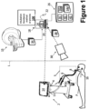
- a mechanical ventilator 2 for providing ventilation therapy to an associated patient P is shown.
- the mechanical ventilator 2 includes an outlet 4 connectable with a patient breathing circuit 5 to deliver mechanical ventilation to the patient P.
- the patient circuit 5 includes typical components for a mechanical ventilator, such as an inlet line 6, an optional outlet line 7 (this may be omitted if the ventilator employs a single-limb patient circuit), a connector or port 8 for connecting with an ETT, and one or more breathing sensors (not shown), such as a gas flow meter, a pressure sensor, end-tidal carbon dioxide (etCO 2 ) sensor, and/or so forth.
- the mechanical ventilator 2 is designed to deliver air, an airoxygen mixture, or other breathable gas (supply not shown) to the outlet 4 at a programmed pressure and/or flow rate to ventilate the patient via an ETT.
- FIGURE 1 also shows a medical imaging device 15 (also referred to as an image acquisition device, imaging device, and so forth).
- the image acquisition device 15 can be a Computed Tomography (CT) image acquisition device, a C-arm imager, or other X-ray imaging device; Magnetic Resonance (MR) image acquisition device; an ultrasound (US) image acquisition device; or a medical imaging device of another modality.
- CT Computed Tomography
- MR Magnetic Resonance
- US ultrasound
- the medical imaging device 15 comprises a CT medical imaging device 15.
- the medical imaging device 15 is used to acquire images of the patient P based upon which ETT sizing is performed. It should be noted that the imaging device 15 may not be located in the same room, or even the same department, as the mechanical ventilator 2.
- the medical imaging device 15 may be located in a radiology laboratory while the mechanical ventilator 2 may be located in an intensive care unit (ICU), cardiac care unit (CCU), in a hospital room assigned to the patient P, or so forth.
- ICU intensive care unit
- CCU cardiac care unit
- separator line L This is diagrammatically indicated in FIGURE 1 by separator line L.
- FIGURE 1 diagrammatically illustrates the patient P intubated with an endotracheal tube (ETT) 16 (the lower portion of which is inside the patient P and hence is shown in phantom).
- the connector or port 8 connects with the ETT 16 to operatively connect the mechanical ventilator 2 to deliver breathable air to the patient P via the ETT 16.
- the mechanical ventilation provided by the mechanical ventilator 2 via the ETT 16 may be therapeutic for a wide range of conditions, such as various types of pulmonary conditions like emphysema or pneumonia, viral or bacterial infections impacting respiration such as a COVID-19 infection or severe influenza, cardiovascular conditions in which the patient P receives breathable gas enriched with oxygen, or so forth.
- FIGURE 1 shows the patient P already intubated. That is, FIGURE 1 shows the patient after a tracheal intubation has been performed to insert the ETT 16 into the patient. However, to safely perform the tracheal intubation, the anesthesiologist or other qualified medical professional first performs an assessment of the patient P to select the ETT size of the ETT 16, and then inserts an ETT of the selected size into the patient P by a tracheal intubation procedure.
- the "ETT size" includes an ETT diameter and a depth of insertion.
- the length of the ETT 16 is longer than the depth of insertion, and the depth of insertion is not a characteristic metric of the ETT per se.
- the depth of insertion is typically determined for a given patient prior to performing the tracheal intubation.
- the ETT sizing for the patient P includes sizing both the ETT diameter and the depth of insertion. That is, the ETT size as used herein includes a tube diameter (specified by an inner diameter (ID) an outer diameter (OD), or both an ID and an OD) and a depth of insertion.
- ID inner diameter
- OD outer diameter
- FIGURE 1 further shows an intubation assistance device 18 configured to assist with intubation of the ETT 16 by providing a recommended ETT size (e.g., diameter and depth of insertion) prior to performing the tracheal intubation.
- the intubation assistance device 18 can comprise an electronic processing device, such as a workstation computer (more generally, a computer), a smart device (e.g., a smartphone, a tablet, and so forth), or server computer or a plurality of server computers, (e.g., interconnected to form a server cluster, cloud computing resource, or so forth).
- the intubation assistance device 18 includes typical components, such as an electronic controller 20 (e.g., an electronic processor or a microprocessor), at least one user input device (e.g., a mouse, a keyboard, a trackball, a finger swipe on a touchscreen of a smart device, and/or the like) 22, and at least one display device 24 (e.g., an LCD display, plasma display, cathode ray tube display, and/or so forth).
- the display device 24 can be a separate component from the electronic processing device 18.
- the display device 24 may also comprise two or more display devices.
- the electronic controller 20 is operatively connected with one or more non-transitory storage media 26.
- the non-transitory storage media 26 may, by way of non-limiting illustrative example, include one or more of a magnetic disk, RAID, or other magnetic storage medium; a solid state drive, flash drive, electronically erasable read-only memory (EEROM) or other electronic memory; an optical disk or other optical storage; various combinations thereof; or so forth; and may be for example a network storage, an internal hard drive of the intubation assistance device 18, various combinations thereof, or so forth. It is to be understood that any reference to a non-transitory medium or media 26 herein is to be broadly construed as encompassing a single medium or multiple media of the same or different types.
- the electronic controller 20 may be embodied as a single electronic processor or as two or more electronic processors.
- the non-transitory storage media 26 stores instructions executable by the at least one electronic controller 20.
- the instructions include instructions to generate a graphical user interface (GUI) 28 for display on the remote operator display device 24.
- GUI graphical user interface
- one or more cameras are disposed in an area where the medical imaging device 15 is located.
- a three-dimensional (3D) camera 30 can be positioned to image the patient P.
- any suitable number of 3D cameras 30 can be used.
- Any suitable 3D camera 30 can be used (see, e.g., FAST Integrated Workflow (siemens-healthineers.com)).
- the non-transitory storage media 26 stores instructions executable by the at least one electronic controller 20 to perform an intubation assistance method or process 100 determining a suitable size and/or insertion depth of the ETT 16 to be used with the mechanical ventilator 2 to provide ventilation therapy to the patient P.
- the mechanical ventilator 2 (and the 3D camera 30 ) can be disposed in a first room of a medical facility, while the image acquisition device 15 and the electronic processing device 18 can be disposed in a second, different room of the medical facility. This is depicted by the dashed line L in the generally "middle" portion of FIGURE 1 .
- the mechanical ventilator 2 and the electronic processing device 18 can be disposed in the first room, while the image acquisition device 15 is disposed in the second room of the medical facility.
- each of the mechanical ventilator 2, the image acquisition device 15 and the electronic processing device 18 can be disposed in separate rooms of the medical facility.
- the patient P may first be transported on a gurney to a radiology lab housing the imaging device 15 for imaging and ETT sizing, and then transported on the gurney from the radiology lab to the location of the mechanical ventilator 2.
- the temporal separation may be even larger than this.
- the acquired images may be used for that routine or diagnostic medical purpose and may also be secondarily leveraged to generate an ETT recommendation that may be stored in the Electronic Health Record (EHR) or other medical record of the patient P.
- EHR Electronic Health Record
- the ETT recommendation can be retrieved from the EHR or other medical record of the patient P and referenced by the anesthesiologist or other qualified medical professional performing the tracheal intubation.
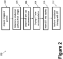
- an illustrative embodiment of the intubation assistance method 100 is diagrammatically shown as a flowchart.
- one or more images 34 of the patient are obtained by the medical imaging device 15.
- the acquired images 34 are CT images 34.
- the electronic controller 20 is configured to control the medical imaging device 15 (i.e., a CT scanner) to acquire the CT images 34 of the upper airway (e.g., from the mouth to the carina) of the patient P.
- the electronic controller 20 is configured to control the medical imaging device 15 to acquire a diagnostic torso CT image of the patient P at a first Xray level, and an extended upper CT image extending upward from the diagnostic torso CT image of the patient P at a second Xray level that is lower than the first Xray level.
- a single CT image 34 may be acquired along a patient axis that covers both the diagnostic torso CT image and the extended upper CT image. The electronic controller 20 is then configured to combine the diagnostic torso CT image and the extended upper CT image to generate the CT images 34 of the upper airway of the patient P.
- This approach of lowering the X-ray level for the extended upper CT image can be advantageous as the throat area, like other parts of the human anatomy, is sensitive to radiation damage, so that a lower X-ray level in this area provides lower dosage. Additionally, the amount of image detail required for performing the disclosed ETT sizing may be less than usually required for the diagnostic or screening task for which the torso CT examination was ordered, so that the lower X-ray level used for the extended upper CT image is sufficient for this purpose.
- This type of imaging sequence workflow may be particularly advantageous when performing the ETT sizing as a secondary result of a torso CT examination ordered for a specific diagnostic or screening task unrelated to ETT sizing.
- information about the patient P is identified from the acquired CT images 34.
- the identified information can include, for example, the upper airways of the patient P, a diameter of trachea of the patient P, and a length of an intubation pathway of the patient P.
- the electronic controller 20 is configured to identify the upper airways of the patient P by segmenting the CT images 34 to identify an upper airway landmark (i.e., 5.0 cm above the carina), the trachea, and the carina of the patient.
- a length of the intubation pathway can be identified based on a distance from the upper airway landmark through the trachea to the carina of the patient P.
- the segmentation might also include the centerline of the trachea.
- the segmentation can additionally provide a length measurement from the teeth to the point where the trachea and the esophagus enter the throat. This information might also be useful for a medical professional to select the depth of insertion of the ETT so as not to enter the esophagus during ETT placement. In other examples, a length starting from lips of the patient P to the carina is measured.
- Any suitable segmentation algorithm can be used in performing the operation 104 (see, e.g., Automatic 3D segmentation of human airway tree in CT image
- Any suitable algorithm can be used for this process (see, e.g., Assessment of automatic segmentation of teeth using a watershed-based method (nih.gov), doi: 10.1259/dmfr.20170220; ToothNet: Automatic Tooth Instance Segmentation and Identification From Cone Beam CT Images (researchgate.net), DOI: 10.1109/CVPR.2019.00653; and Rapid Automatic Segmentation and Visualization of Teeth in CT-Scan Data (scialert.net), DOI: 10.3923/jas.2009.2031.2044).
- the head of the patient P may not be in a desired position (i.e., bent backwards, as is the usual positioning of the head during tracheal intubation).
- the electronic controller 20 is optionally configured to retrieve a patient anatomical model 36 (which contains the head and neck, and optionally at least the upper part of the thorax) from the non-transitory computer readable media 26.
- the electronic controller 20 may use the patient anatomical model 36 to deform the image of the head and neck of the patient P shown in the CT images 34 into a desired position resulting in deformed CT images 34d (e.g., with the head bent backwards).
- the patient anatomical model 36 represents the anatomy and, optionally biomechanical properties, of humans.
- the patient anatomical model 36 can be relatively simple (e.g., allowing an elastic deformation of the CT image(s) 34 ) or detailed (e.g., it can consider surrounding anatomical structures (e.g., rigid bones, contractable muscles, tendons, and soft tissue)).
- any suitable patient anatomical model 36 can be used (see, e.g., " Biomechanical modelling of neck flexion for deformable alignment of the salivary glands in head and neck cancer images", Phys Med Biol. 2019 Sep 5;64(17):175018. doi: 10.1088/1361-6560/ab2f13 ).
- the acquired CT images 34 do not depict at least a portion of the upper airway of the patient P (e.g., due to the patient P moving during image acquisition, the patient P being incorrectly positioned for imaging, and so forth).
- the electronic controller 20 is configured to adapt or modify the patient anatomical model 36 based on one or more 3D images 38 of the patient P, acquired via the 3D camera 30.
- the 3D images 38 show an exterior (e.g., head and thorax) of the patient P.
- the electronic controller 20 is configured to generate the 3D images 38 by generating a 3D model 40 from the CT images 34, and by generating the 3D images 38 of the exterior of the patient P from the 3D model 40.
- the 3D images 38 of the exterior of the patient P are obtained by the 3D camera(s) 30 and transmitted to the electronic processing device 18.
- the electronic controller 20 is then configured to register the patient anatomical model 36 with the CT images 34 to obtain a hybrid imaging data set, which is used to determine the intubation pathway.
- the identifying information about the patient P is further based on the extracted patient anatomical model 36.
- the acquired CT images 34 do not depict at least a portion of the upper airway of the patient P (e.g., due to the patient P moving during image acquisition, the patient P being incorrectly positioned for imaging, and so forth).
- the electronic controller 20 is configured to retrieve a patient anatomical (head, neck, and optionally thorax) model 36 from the non-transitory computer readable media 26.
- the electronic controller 20 is further configured to identify the region where the patient anatomical model 36 and the CT image 34 overlap and to adjust parameters of the model such that the adjusted patient anatomical model 36a fits in the overlapping region to the CT images 34.
- the electronic controller 20 is further configured to generate a hybrid imaging data set from the measured CT images 34 (where available) and the adjusted patient anatomical model 36a (where desired information from images 34 are missing). The hybrid imaging data set is subsequently used to determine the intubation pathway.
- the method 100 proceeds to an operation 106, in which the electronic controller 20 is configured to determine a recommended ETT size for the patient P from the determined diameter of the trachea and the determined length of the intubation pathway.
- an ETT model 42 can be retrieved from the non-transitory computer readable media 26.
- the electronic controller 20 is configured to use the ETT model 42 to determine a desired stiffness of the ETT 16 by inputting the determined diameter of the trachea and the determined length of the intubation pathway to the ETT model 42, which then outputs the recommended size of the ETT 16 for the patient P including a recommended depth of insertion of the ETT 16.
- the identification of the intubation pathway length is further based on the stiffness of the ETT 16.
- the ETT 16 may touch or contact a tracheal wall at different sides.
- the ETT model 42 can be used to account for a difference between the actual required depth of insertion of the ETT 16 and the length of the center line of the determined length of the intubation pathway.
- the ETT 16 having the recommended ETT size for the patient P is inserted into the trachea of the patient P.
- the medical professional can use markings conventionally included on the ETT 16 to determine progress of the insertion depth of the ETT.
- the ETT 16 is inserted into the trachea to the recommended depth of insertion so as to place the tip of the ETT 16 at a desired point (e.g., 5.0 cm above the carina).
- a headsup display such as augmented reality (AR) glasses or headset (e.g., a Microsoft HoloLens, Bellevue, WA, United States) (not shown) can be used to guide the medical professional during placement (and subsequent removal) of the ETT 16.
- AR augmented reality
- WA United States
- the AR device can be used to indicate the position of the ETT 16 in relation to relevant anatomical structures within the patient's body derived from the CT images 34 and/or from the patient anatomical model 36. This further aids in improving the accuracy of positioning of the ETT 16 and thereby decrease the risk of complications.
- the ETT 16 is connected to the mechanical ventilator 2 (e.g., at the port or connector 8 ).
- the medical professional then operates the mechanical ventilator 2 to deliver ventilation therapy to the patient P with the mechanical ventilator 2.
- the CT image acquisition and the ventilation therapy can be separated in time by days, weeks, months, or even years.
- the optimal ETT size for the patient including the ETT diameter and depth of insertion can be calculated routinely and stored in the EHR (e.g., similar to a blood type of the patient). If the patient requires at any time later mechanical ventilation (e.g., after a car accident) then the information can be retrieved from the EHR. This may be particularly useful since the ETT 16 may be placed by an emergency medicine technician rather than a consultant anesthetist, and often in a situation where time pressures and clinical issues (e.g., blood in the airway) may make ETT placement more difficult.
- FIGURE 3 shows an example of the planning of the intubation pathway (e.g., operation 102 ) and the recommended size of the ETT 16 (e.g., operation 104 ).
- FIGURE 3 shows side and front views of a CT image 34 of the patient's head and neck. The intubation pathway is shown in both views extends from the front teeth of the patient P (depicted by reference character 50 ) to the desired endpoint (depicted by reference character 52 ) (e.g., 5.0 cm above the carina).
Landscapes
- Health & Medical Sciences (AREA)
- Engineering & Computer Science (AREA)
- Life Sciences & Earth Sciences (AREA)
- Medical Informatics (AREA)
- General Health & Medical Sciences (AREA)
- Surgery (AREA)
- Biomedical Technology (AREA)
- Heart & Thoracic Surgery (AREA)
- Animal Behavior & Ethology (AREA)
- Public Health (AREA)
- Veterinary Medicine (AREA)
- Physics & Mathematics (AREA)
- Pulmonology (AREA)
- Nuclear Medicine, Radiotherapy & Molecular Imaging (AREA)
- Molecular Biology (AREA)
- Radiology & Medical Imaging (AREA)
- Pathology (AREA)
- Biophysics (AREA)
- Computer Vision & Pattern Recognition (AREA)
- Theoretical Computer Science (AREA)
- Optics & Photonics (AREA)
- General Physics & Mathematics (AREA)
- Otolaryngology (AREA)
- High Energy & Nuclear Physics (AREA)
- Anesthesiology (AREA)
- Emergency Medicine (AREA)
- Hematology (AREA)
- Physiology (AREA)
- Quality & Reliability (AREA)
- Dentistry (AREA)
- Oral & Maxillofacial Surgery (AREA)
- Robotics (AREA)
- Apparatus For Radiation Diagnosis (AREA)
Claims (10)
- Intubationshilfsvorrichtung (18), die eine elektronische Steuereinheit (20) umfasst, die so konfiguriert ist, dass sie:anhand eines oder mehrerer Bilder (34) eines Patienten (P) Informationen über den Patienten, die mindestens einen Durchmesser einer Luftröhre und eine Länge eines Intubationsweges beinhalten, identifiziert;eine empfohlene Größe eines Endotrachealtubus, ETT, (16), die einen ETT-Durchmesser und eine ETT-Einführtiefe beinhaltet, anhand des bestimmten Durchmessers der Luftröhre und der bestimmten Länge des Intubationsweges bestimmt; unddie empfohlene ETT-Größe auf einer Anzeigevorrichtung (14) anzeigt,wobei die elektronische Steuereinheit so konfiguriert ist, dass sie die oberen Atemwege des Patienten identifiziert durch:
Segmentieren des einen oder der mehreren Bilder, um ein Orientierungsmerkmal der oberen Atemwege, die Luftröhre und die Carina des Patienten zu identifizieren. - Intubationshilfsvorrichtung (18) nach Anspruch 1, wobei das Segmentieren weiter beinhaltet:
Identifizieren der Länge des Intubationsweges auf Basis einer Distanz vom Orientierungsmerkmal der oberen Atemwege durch die Luftröhre bis zur Carina des Patienten. - Intubationshilfsvorrichtung (18) nach Anspruch 1, wobei die elektronische Steuereinheit (20) so konfiguriert ist, dass sie die ETT-Größe bestimmt durch:
Verwenden eines ETT-Modells (42), um eine Steifheit des ETT zu bestimmen, wobei das Bestimmen der ETT-Einführtiefe weiter auf der Steifheit des ETT basiert. - Intubationshilfsvorrichtung (18) nach Anspruch 1, wobei die elektronische Steuereinheit (20) weiter so konfiguriert ist, dass sie:
das eine oder die mehreren Bilder an ein anatomisches Patientenmodell (36) anpasst, um das eine oder die mehreren Bilder (34) des Patienten (P) in eine gewünschte Position zu verformen, wobei die Informationen über den Patienten anhand des einen oder der mehreren angepassten Bilder (34a) identifiziert werden. - Intubationshilfsvorrichtung (18) nach Anspruch 1, wobei das eine oder die mehreren Bilder (34) mindestens einen Teil der oberen Atemwege des Patienten (P) nicht abbilden und die elektronische Steuereinheit (20) weiter so konfiguriert ist, dass sie:ein anatomisches Patientenmodell (36) auf Basis eines oder mehrerer Bilder eines Äußeren des Patienten modifiziert;wobei das Identifizieren von Informationen über den Patienten weiter auf dem anatomischen Patientenmodell basiert, das auf Basis des einen oder der mehreren Bilder des Äußeren des Patienten modifiziert wurde.
- Intubationshilfsvorrichtung (18) nach Anspruch 5, wobei die elektronische Steuereinheit (20) weiter so konfiguriert ist, dass sie das eine oder die mehreren Bilder des Äußeren des Patienten (P) erzeugt durch:Erzeugen eines 3D-Bildgebungsmodells (40) anhand des einen oder der mehreren Bilder (34) des Patienten; undErzeugen des einen oder der mehreren Bilder des Äußeren des Patienten anhand des 3D-Bildgebungsmodells.
- Intubationshilfsvorrichtung (18) nach Anspruch 5, wobei die Bilder des Äußeren des Patienten (P) eines oder mehrere 3D-Bildern (38) umfasst, die von einer oder mehreren 3D-Kameras (30) aufgenommen wurden.
- Intubationshilfsvorrichtung (18) nach Anspruch 5, wobei die elektronische Steuereinheit (20) so konfiguriert ist, dass sie:das aus dem einen oder den mehreren Bildern des Äußeren des Patienten (P) extrahierte anatomische Patientenmodell (36) mit dem einen oder den mehreren Bildern registriert, um einen hybriden Bildgebungsdatensatz zu erzeugen; undden Intubationsweg auf Basis des hybriden Bildgebungsdatensatzes bestimmt.
- Intubationshilfsvorrichtung (18) nach Anspruch 1, wobei die elektronische Steuereinheit (20) weiter so konfiguriert ist, dass sie einen Computertomographie- (CT) Scanner steuert, um das eine oder die mehreren Bilder der oberen Atemwege des Patienten aufzunehmen.
- Intubationshilfsvorrichtung (18) nach Anspruch 9, wobei die elektronische Steuereinheit (20) so konfiguriert ist, dass sie den CT-Scanner steuert, um das eine oder die mehreren Bilder (34) der oberen Atemwege des Patienten (P) durch Operationen aufzunehmen, welche beinhalten:Steuern des CT-Scanners, um ein diagnostisches CT-Bild des Rumpfes in einer ersten Röntgenebene aufzunehmen;Steuern des CT-Scanners, um ein erweitertes oberes CT-Bild, das sich vom diagnostischen CT-Bild des Rumpfes nach oben erstreckt, in einer zweiten Röntgenebene aufzunehmen, die niedriger ist als die erste Röntgenebene; undKombinieren des diagnostischen CT-Bildes des Rumpfes und des erweiterten oberen CT-Bildes, um das eine oder die mehreren Bilder der oberen Atemwege des Patienten zu erzeugen.
Applications Claiming Priority (2)
| Application Number | Priority Date | Filing Date | Title |
|---|---|---|---|
| US202163213247P | 2021-06-22 | 2021-06-22 | |
| PCT/EP2022/065957 WO2022268549A1 (en) | 2021-06-22 | 2022-06-13 | Imaging-based sizing optimization of endotracheal tube for mechanical ventilation |
Publications (2)
| Publication Number | Publication Date |
|---|---|
| EP4358839A1 EP4358839A1 (de) | 2024-05-01 |
| EP4358839B1 true EP4358839B1 (de) | 2024-09-18 |
Family
ID=82214516
Family Applications (1)
| Application Number | Title | Priority Date | Filing Date |
|---|---|---|---|
| EP22733598.1A Active EP4358839B1 (de) | 2021-06-22 | 2022-06-13 | Bildgebungsbasierte grössenoptimierung eines endotrachealtubus für mechanische beatmung |
Country Status (5)
| Country | Link |
|---|---|
| US (1) | US12427277B2 (de) |
| EP (1) | EP4358839B1 (de) |
| JP (1) | JP2024522503A (de) |
| CN (1) | CN117545418A (de) |
| WO (1) | WO2022268549A1 (de) |
Families Citing this family (2)
| Publication number | Priority date | Publication date | Assignee | Title |
|---|---|---|---|---|
| KR102905828B1 (ko) * | 2023-06-19 | 2025-12-29 | 한림대학교 산학협력단 | 기관 삽관의 적정 깊이를 예측하는 방법 및 장치 |
| CN118629625B (zh) * | 2024-06-03 | 2025-02-25 | 首都医科大学附属北京朝阳医院 | 一种呼吸道路径编码的方法、装置、存储介质及电子设备 |
Family Cites Families (8)
| Publication number | Priority date | Publication date | Assignee | Title |
|---|---|---|---|---|
| WO1998036683A1 (en) | 1997-02-25 | 1998-08-27 | Temple University - Of The Commonwealth System Of Higher Education | Non-invasive radiographic method for analyzation of a body element |
| US6705319B1 (en) * | 2000-05-26 | 2004-03-16 | Purdue Research Foundation | Miniature acoustical guidance and monitoring system for tube or catheter placement |
| US8721589B1 (en) * | 2009-11-30 | 2014-05-13 | Spiritus Technologies, LLC | Endotracheal tube cuff inflation device and methods |
| US20120197086A1 (en) | 2011-01-31 | 2012-08-02 | Nellcor Puritan Bennett Llc | Medical visualization technique and apparatus |
| EP2888991B1 (de) | 2013-04-15 | 2017-11-01 | Olympus Corporation | Endoskopsystem |
| US10722671B2 (en) * | 2014-05-19 | 2020-07-28 | Securisyn Medical, Llc | Method and apparatus for determining optimal endotracheal tube size |
| EP3716106B1 (de) * | 2019-03-27 | 2022-06-15 | Assistance Publique, Hopitaux De Paris | Verfahren zum entwerfen und zur validierung der form und positionierung einer kanüle für einen patienten durch simulation des einführens in die luftröhre |
| US11712329B2 (en) | 2019-04-04 | 2023-08-01 | Children's Medical Center Corporation | Airway stents |
-
2022
- 2022-05-06 US US17/738,326 patent/US12427277B2/en active Active
- 2022-06-13 JP JP2023573041A patent/JP2024522503A/ja not_active Ceased
- 2022-06-13 WO PCT/EP2022/065957 patent/WO2022268549A1/en not_active Ceased
- 2022-06-13 EP EP22733598.1A patent/EP4358839B1/de active Active
- 2022-06-13 CN CN202280044450.3A patent/CN117545418A/zh active Pending
Also Published As
| Publication number | Publication date |
|---|---|
| JP2024522503A (ja) | 2024-06-21 |
| CN117545418A (zh) | 2024-02-09 |
| US12427277B2 (en) | 2025-09-30 |
| US20220401678A1 (en) | 2022-12-22 |
| EP4358839A1 (de) | 2024-05-01 |
| WO2022268549A1 (en) | 2022-12-29 |
Similar Documents
| Publication | Publication Date | Title |
|---|---|---|
| US12245821B2 (en) | Endotracheal tube size selection and insertion depth estimation using statistical shape modelling and virtual fitting | |
| CN106232011B (zh) | 气管标记 | |
| US20120197086A1 (en) | Medical visualization technique and apparatus | |
| JP4583658B2 (ja) | 内視鏡システム | |
| US20160022943A1 (en) | Method and apparatus for determining optimal endotracheal tube size | |
| US12427277B2 (en) | Imaging-based sizing optimization of endotracheal tube for mechanical ventilation | |
| Van Zundert et al. | Supraglottic airway devices: present state and outlook for 2050 | |
| EP4537353B1 (de) | Mechanische beatmungskonfiguration zur mechanischen beatmung eines patienten mit begrenzten oder keinen bildgebungsdaten des patienten | |
| US12539380B2 (en) | Digital twin of lung that is calibrated and updated with mechanical ventilator data and bed-side imaging information for safe mechanical ventilation | |
| JP2024522503A5 (de) | ||
| US12340527B2 (en) | Inter- and extrapolation of chest image and mechanical ventilation settings into a time lapse series for progression monitoring and outcome prediction during long term mechanical ventilation | |
| US20230133142A1 (en) | Patient stratification and clinical decision support on mechanical ventilation settings from sonar responses through an endotracheal tube (ett) | |
| JP2025531014A (ja) | 呼吸努力の存在下での安全な換気 | |
| US12564377B2 (en) | Augmented reality for ultrasound exams at the point-of-care in combination with mechanical ventilation | |
| US12594391B2 (en) | Model-guided imaging for mechanical ventilation | |
| EP3454293A1 (de) | Verfahren und vorrichtung zur verbesserung der darstellung der bronchialen atemwege unter verwendung von vaskulärer morphologie | |
| US20240164741A1 (en) | Diaphragmatic ultrasonography image alignment and motion compensation for contralateral comparison | |
| US20230094608A1 (en) | Pendelluft detection by acoustic interferometry through an endotracheal tube | |
| CN119546245A (zh) | 用于跟踪导管的装置 | |
| Wojtczak et al. | Tomography, Ultrasound, and Craniofacial Phenotyping |
Legal Events
| Date | Code | Title | Description |
|---|---|---|---|
| STAA | Information on the status of an ep patent application or granted ep patent |
Free format text: STATUS: UNKNOWN |
|
| STAA | Information on the status of an ep patent application or granted ep patent |
Free format text: STATUS: THE INTERNATIONAL PUBLICATION HAS BEEN MADE |
|
| PUAI | Public reference made under article 153(3) epc to a published international application that has entered the european phase |
Free format text: ORIGINAL CODE: 0009012 |
|
| STAA | Information on the status of an ep patent application or granted ep patent |
Free format text: STATUS: REQUEST FOR EXAMINATION WAS MADE |
|
| GRAP | Despatch of communication of intention to grant a patent |
Free format text: ORIGINAL CODE: EPIDOSNIGR1 |
|
| STAA | Information on the status of an ep patent application or granted ep patent |
Free format text: STATUS: GRANT OF PATENT IS INTENDED |
|
| 17P | Request for examination filed |
Effective date: 20240122 |
|
| AK | Designated contracting states |
Kind code of ref document: A1 Designated state(s): AL AT BE BG CH CY CZ DE DK EE ES FI FR GB GR HR HU IE IS IT LI LT LU LV MC MK MT NL NO PL PT RO RS SE SI SK SM TR |
|
| DAV | Request for validation of the european patent (deleted) | ||
| DAX | Request for extension of the european patent (deleted) | ||
| INTG | Intention to grant announced |
Effective date: 20240419 |
|
| GRAS | Grant fee paid |
Free format text: ORIGINAL CODE: EPIDOSNIGR3 |
|
| GRAA | (expected) grant |
Free format text: ORIGINAL CODE: 0009210 |
|
| STAA | Information on the status of an ep patent application or granted ep patent |
Free format text: STATUS: THE PATENT HAS BEEN GRANTED |
|
| AK | Designated contracting states |
Kind code of ref document: B1 Designated state(s): AL AT BE BG CH CY CZ DE DK EE ES FI FR GB GR HR HU IE IS IT LI LT LU LV MC MK MT NL NO PL PT RO RS SE SI SK SM TR |
|
| REG | Reference to a national code |
Ref country code: GB Ref legal event code: FG4D |
|
| REG | Reference to a national code |
Ref country code: CH Ref legal event code: EP |
|
| REG | Reference to a national code |
Ref country code: IE Ref legal event code: FG4D |
|
| REG | Reference to a national code |
Ref country code: DE Ref legal event code: R096 Ref document number: 602022006240 Country of ref document: DE |
|
| REG | Reference to a national code |
Ref country code: LT Ref legal event code: MG9D |
|
| PG25 | Lapsed in a contracting state [announced via postgrant information from national office to epo] |
Ref country code: NO Free format text: LAPSE BECAUSE OF FAILURE TO SUBMIT A TRANSLATION OF THE DESCRIPTION OR TO PAY THE FEE WITHIN THE PRESCRIBED TIME-LIMIT Effective date: 20241218 |
|
| PG25 | Lapsed in a contracting state [announced via postgrant information from national office to epo] |
Ref country code: GR Free format text: LAPSE BECAUSE OF FAILURE TO SUBMIT A TRANSLATION OF THE DESCRIPTION OR TO PAY THE FEE WITHIN THE PRESCRIBED TIME-LIMIT Effective date: 20241219 Ref country code: FI Free format text: LAPSE BECAUSE OF FAILURE TO SUBMIT A TRANSLATION OF THE DESCRIPTION OR TO PAY THE FEE WITHIN THE PRESCRIBED TIME-LIMIT Effective date: 20240918 |
|
| PG25 | Lapsed in a contracting state [announced via postgrant information from national office to epo] |
Ref country code: BG Free format text: LAPSE BECAUSE OF FAILURE TO SUBMIT A TRANSLATION OF THE DESCRIPTION OR TO PAY THE FEE WITHIN THE PRESCRIBED TIME-LIMIT Effective date: 20240918 |
|
| PG25 | Lapsed in a contracting state [announced via postgrant information from national office to epo] |
Ref country code: LV Free format text: LAPSE BECAUSE OF FAILURE TO SUBMIT A TRANSLATION OF THE DESCRIPTION OR TO PAY THE FEE WITHIN THE PRESCRIBED TIME-LIMIT Effective date: 20240918 |
|
| PG25 | Lapsed in a contracting state [announced via postgrant information from national office to epo] |
Ref country code: HR Free format text: LAPSE BECAUSE OF FAILURE TO SUBMIT A TRANSLATION OF THE DESCRIPTION OR TO PAY THE FEE WITHIN THE PRESCRIBED TIME-LIMIT Effective date: 20240918 |
|
| REG | Reference to a national code |
Ref country code: NL Ref legal event code: MP Effective date: 20240918 |
|
| PG25 | Lapsed in a contracting state [announced via postgrant information from national office to epo] |
Ref country code: RS Free format text: LAPSE BECAUSE OF FAILURE TO SUBMIT A TRANSLATION OF THE DESCRIPTION OR TO PAY THE FEE WITHIN THE PRESCRIBED TIME-LIMIT Effective date: 20241218 |
|
| PG25 | Lapsed in a contracting state [announced via postgrant information from national office to epo] |
Ref country code: RS Free format text: LAPSE BECAUSE OF FAILURE TO SUBMIT A TRANSLATION OF THE DESCRIPTION OR TO PAY THE FEE WITHIN THE PRESCRIBED TIME-LIMIT Effective date: 20241218 Ref country code: NO Free format text: LAPSE BECAUSE OF FAILURE TO SUBMIT A TRANSLATION OF THE DESCRIPTION OR TO PAY THE FEE WITHIN THE PRESCRIBED TIME-LIMIT Effective date: 20241218 Ref country code: LV Free format text: LAPSE BECAUSE OF FAILURE TO SUBMIT A TRANSLATION OF THE DESCRIPTION OR TO PAY THE FEE WITHIN THE PRESCRIBED TIME-LIMIT Effective date: 20240918 Ref country code: HR Free format text: LAPSE BECAUSE OF FAILURE TO SUBMIT A TRANSLATION OF THE DESCRIPTION OR TO PAY THE FEE WITHIN THE PRESCRIBED TIME-LIMIT Effective date: 20240918 Ref country code: GR Free format text: LAPSE BECAUSE OF FAILURE TO SUBMIT A TRANSLATION OF THE DESCRIPTION OR TO PAY THE FEE WITHIN THE PRESCRIBED TIME-LIMIT Effective date: 20241219 Ref country code: FI Free format text: LAPSE BECAUSE OF FAILURE TO SUBMIT A TRANSLATION OF THE DESCRIPTION OR TO PAY THE FEE WITHIN THE PRESCRIBED TIME-LIMIT Effective date: 20240918 Ref country code: BG Free format text: LAPSE BECAUSE OF FAILURE TO SUBMIT A TRANSLATION OF THE DESCRIPTION OR TO PAY THE FEE WITHIN THE PRESCRIBED TIME-LIMIT Effective date: 20240918 |
|
| REG | Reference to a national code |
Ref country code: AT Ref legal event code: MK05 Ref document number: 1724009 Country of ref document: AT Kind code of ref document: T Effective date: 20240918 |
|
| PG25 | Lapsed in a contracting state [announced via postgrant information from national office to epo] |
Ref country code: NL Free format text: LAPSE BECAUSE OF FAILURE TO SUBMIT A TRANSLATION OF THE DESCRIPTION OR TO PAY THE FEE WITHIN THE PRESCRIBED TIME-LIMIT Effective date: 20240918 |
|
| PG25 | Lapsed in a contracting state [announced via postgrant information from national office to epo] |
Ref country code: IS Free format text: LAPSE BECAUSE OF FAILURE TO SUBMIT A TRANSLATION OF THE DESCRIPTION OR TO PAY THE FEE WITHIN THE PRESCRIBED TIME-LIMIT Effective date: 20250118 Ref country code: PT Free format text: LAPSE BECAUSE OF FAILURE TO SUBMIT A TRANSLATION OF THE DESCRIPTION OR TO PAY THE FEE WITHIN THE PRESCRIBED TIME-LIMIT Effective date: 20250120 |
|
| PG25 | Lapsed in a contracting state [announced via postgrant information from national office to epo] |
Ref country code: RO Free format text: LAPSE BECAUSE OF FAILURE TO SUBMIT A TRANSLATION OF THE DESCRIPTION OR TO PAY THE FEE WITHIN THE PRESCRIBED TIME-LIMIT Effective date: 20240918 Ref country code: SM Free format text: LAPSE BECAUSE OF FAILURE TO SUBMIT A TRANSLATION OF THE DESCRIPTION OR TO PAY THE FEE WITHIN THE PRESCRIBED TIME-LIMIT Effective date: 20240918 |
|
| PG25 | Lapsed in a contracting state [announced via postgrant information from national office to epo] |
Ref country code: ES Free format text: LAPSE BECAUSE OF FAILURE TO SUBMIT A TRANSLATION OF THE DESCRIPTION OR TO PAY THE FEE WITHIN THE PRESCRIBED TIME-LIMIT Effective date: 20240918 |
|
| PG25 | Lapsed in a contracting state [announced via postgrant information from national office to epo] |
Ref country code: AT Free format text: LAPSE BECAUSE OF FAILURE TO SUBMIT A TRANSLATION OF THE DESCRIPTION OR TO PAY THE FEE WITHIN THE PRESCRIBED TIME-LIMIT Effective date: 20240918 Ref country code: EE Free format text: LAPSE BECAUSE OF FAILURE TO SUBMIT A TRANSLATION OF THE DESCRIPTION OR TO PAY THE FEE WITHIN THE PRESCRIBED TIME-LIMIT Effective date: 20240918 |
|
| PG25 | Lapsed in a contracting state [announced via postgrant information from national office to epo] |
Ref country code: PL Free format text: LAPSE BECAUSE OF FAILURE TO SUBMIT A TRANSLATION OF THE DESCRIPTION OR TO PAY THE FEE WITHIN THE PRESCRIBED TIME-LIMIT Effective date: 20240918 Ref country code: CZ Free format text: LAPSE BECAUSE OF FAILURE TO SUBMIT A TRANSLATION OF THE DESCRIPTION OR TO PAY THE FEE WITHIN THE PRESCRIBED TIME-LIMIT Effective date: 20240918 |
|
| PG25 | Lapsed in a contracting state [announced via postgrant information from national office to epo] |
Ref country code: IT Free format text: LAPSE BECAUSE OF FAILURE TO SUBMIT A TRANSLATION OF THE DESCRIPTION OR TO PAY THE FEE WITHIN THE PRESCRIBED TIME-LIMIT Effective date: 20240918 Ref country code: SK Free format text: LAPSE BECAUSE OF FAILURE TO SUBMIT A TRANSLATION OF THE DESCRIPTION OR TO PAY THE FEE WITHIN THE PRESCRIBED TIME-LIMIT Effective date: 20240918 |
|
| REG | Reference to a national code |
Ref country code: DE Ref legal event code: R097 Ref document number: 602022006240 Country of ref document: DE |
|
| PG25 | Lapsed in a contracting state [announced via postgrant information from national office to epo] |
Ref country code: DK Free format text: LAPSE BECAUSE OF FAILURE TO SUBMIT A TRANSLATION OF THE DESCRIPTION OR TO PAY THE FEE WITHIN THE PRESCRIBED TIME-LIMIT Effective date: 20240918 |
|
| PLBE | No opposition filed within time limit |
Free format text: ORIGINAL CODE: 0009261 |
|
| STAA | Information on the status of an ep patent application or granted ep patent |
Free format text: STATUS: NO OPPOSITION FILED WITHIN TIME LIMIT |
|
| 26N | No opposition filed |
Effective date: 20250619 |
|
| PG25 | Lapsed in a contracting state [announced via postgrant information from national office to epo] |
Ref country code: SE Free format text: LAPSE BECAUSE OF FAILURE TO SUBMIT A TRANSLATION OF THE DESCRIPTION OR TO PAY THE FEE WITHIN THE PRESCRIBED TIME-LIMIT Effective date: 20240918 |
|
| REG | Reference to a national code |
Ref country code: DE Ref legal event code: R119 Ref document number: 602022006240 Country of ref document: DE |
|
| REG | Reference to a national code |
Ref country code: CH Ref legal event code: H13 Free format text: ST27 STATUS EVENT CODE: U-0-0-H10-H13 (AS PROVIDED BY THE NATIONAL OFFICE) Effective date: 20260127 |
|
| PG25 | Lapsed in a contracting state [announced via postgrant information from national office to epo] |
Ref country code: MC Free format text: LAPSE BECAUSE OF FAILURE TO SUBMIT A TRANSLATION OF THE DESCRIPTION OR TO PAY THE FEE WITHIN THE PRESCRIBED TIME-LIMIT Effective date: 20240918 |
|
| PG25 | Lapsed in a contracting state [announced via postgrant information from national office to epo] |
Ref country code: LU Free format text: LAPSE BECAUSE OF NON-PAYMENT OF DUE FEES Effective date: 20250613 |
|
| REG | Reference to a national code |
Ref country code: BE Ref legal event code: MM Effective date: 20250630 |
|
| PG25 | Lapsed in a contracting state [announced via postgrant information from national office to epo] |
Ref country code: DE Free format text: LAPSE BECAUSE OF NON-PAYMENT OF DUE FEES Effective date: 20260101 Ref country code: IE Free format text: LAPSE BECAUSE OF NON-PAYMENT OF DUE FEES Effective date: 20250613 |
|
| PG25 | Lapsed in a contracting state [announced via postgrant information from national office to epo] |
Ref country code: BE Free format text: LAPSE BECAUSE OF NON-PAYMENT OF DUE FEES Effective date: 20250630 |
|
| PG25 | Lapsed in a contracting state [announced via postgrant information from national office to epo] |
Ref country code: FR Free format text: LAPSE BECAUSE OF NON-PAYMENT OF DUE FEES Effective date: 20250630 |
|
| PG25 | Lapsed in a contracting state [announced via postgrant information from national office to epo] |
Ref country code: CH Free format text: LAPSE BECAUSE OF NON-PAYMENT OF DUE FEES Effective date: 20250630 |