EP4358651A1 - Commande d'éclairage - Google Patents
Commande d'éclairage Download PDFInfo
- Publication number
- EP4358651A1 EP4358651A1 EP22202060.4A EP22202060A EP4358651A1 EP 4358651 A1 EP4358651 A1 EP 4358651A1 EP 22202060 A EP22202060 A EP 22202060A EP 4358651 A1 EP4358651 A1 EP 4358651A1
- Authority
- EP
- European Patent Office
- Prior art keywords
- lighting control
- light
- user
- control information
- luminaires
- Prior art date
- Legal status (The legal status is an assumption and is not a legal conclusion. Google has not performed a legal analysis and makes no representation as to the accuracy of the status listed.)
- Pending
Links
- 238000004891 communication Methods 0.000 claims abstract description 60
- 238000000034 method Methods 0.000 claims abstract description 38
- 230000008859 change Effects 0.000 claims description 12
- 230000005540 biological transmission Effects 0.000 claims description 8
- 230000002123 temporal effect Effects 0.000 claims description 4
- 238000004590 computer program Methods 0.000 description 20
- 238000013475 authorization Methods 0.000 description 12
- 238000010586 diagram Methods 0.000 description 12
- 238000005286 illumination Methods 0.000 description 10
- 238000013459 approach Methods 0.000 description 8
- 230000000694 effects Effects 0.000 description 7
- 238000009795 derivation Methods 0.000 description 6
- 230000006870 function Effects 0.000 description 6
- 230000007613 environmental effect Effects 0.000 description 5
- 230000007935 neutral effect Effects 0.000 description 5
- 230000004044 response Effects 0.000 description 5
- 239000003086 colorant Substances 0.000 description 3
- 230000000007 visual effect Effects 0.000 description 3
- 230000027288 circadian rhythm Effects 0.000 description 2
- 230000008878 coupling Effects 0.000 description 2
- 238000010168 coupling process Methods 0.000 description 2
- 238000005859 coupling reaction Methods 0.000 description 2
- 238000009434 installation Methods 0.000 description 2
- 238000013507 mapping Methods 0.000 description 2
- 238000012545 processing Methods 0.000 description 2
- 230000033764 rhythmic process Effects 0.000 description 2
- 238000012546 transfer Methods 0.000 description 2
- 230000003213 activating effect Effects 0.000 description 1
- 238000003491 array Methods 0.000 description 1
- 230000001010 compromised effect Effects 0.000 description 1
- 238000010276 construction Methods 0.000 description 1
- 230000008094 contradictory effect Effects 0.000 description 1
- 230000003247 decreasing effect Effects 0.000 description 1
- 230000008569 process Effects 0.000 description 1
Images


Classifications
-
- H—ELECTRICITY
- H05—ELECTRIC TECHNIQUES NOT OTHERWISE PROVIDED FOR
- H05B—ELECTRIC HEATING; ELECTRIC LIGHT SOURCES NOT OTHERWISE PROVIDED FOR; CIRCUIT ARRANGEMENTS FOR ELECTRIC LIGHT SOURCES, IN GENERAL
- H05B47/00—Circuit arrangements for operating light sources in general, i.e. where the type of light source is not relevant
- H05B47/10—Controlling the light source
- H05B47/175—Controlling the light source by remote control
- H05B47/19—Controlling the light source by remote control via wireless transmission
Definitions
- the present invention relates to sharing of environmental data captured by one or more sensors that are coupled toa lighting control network.
- luminaires of a lighting system are nowadays automatically or semi-automatically controlled e.g. based on sensor data captured in the illuminated space, to provide illumination that guarantees illumination levels considered suitable for the illuminated space by a lighting designer.
- the suitable illumination levels may be based on, for example, relevant standards or norms that define requirements and/or recommendations for illumination levels in spaces intended for specific purposes.
- the automated or semi-automated lighting control may be applied for providing suitable trade-off between ensuring sufficient illumination level when the space under consideration is occupied and providing energy savings via keeping the lights at a lower level or completely off when the space under consideration is unoccupied, in many scenarios there is a need - and sometimes even a requirement - to also enable manual lighting control to account for specific needs and/or preferences of one or more occupants of the space under consideration.
- the manual control may be enabled e.g.
- control panels arranged in the illuminated space or in its proximity or via a digital interface that may be accessed by user device which may be designed for this specific purpose (such as a remote control unit) or provided via operation of a general purpose user device (such as a mobile phone, a tablet computer, a laptop computer, etc.).
- user device which may be designed for this specific purpose (such as a remote control unit) or provided via operation of a general purpose user device (such as a mobile phone, a tablet computer, a laptop computer, etc.).
- a method for lighting control comprising: receiving, over one or more wireless communication channels at a lighting control apparatus, respective one or more lighting control messages from one or more user apparatuses, wherein the one or more lighting control messages received from a respective one of the one or more user apparatuses include respective lighting control information at one of two or more predefined priority levels; determining, by the lighting control apparatus, one or more lighting control actions for controlling respective light outputs of one or more luminaires based on the respective lighting control information received from said one or more user apparatuses in accordance with the respective priority levels; and controlling, by the lighting control apparatus, the respective light outputs of one or more luminaires in accordance with the determined one or more lighting control actions.
- a lighting control apparatus configured to: receive, over one or more wireless communication channels, respective one or more lighting control messages from one or more user apparatuses, wherein the one or more lighting control messages received from a respective one of the one or more user apparatuses include respective lighting control information at one of two or more predefined priority levels; determine one or more lighting control actions for controlling respective light outputs of one or more luminaires (120) based on the respective lighting control information received from said one or more user apparatuses (150) in accordance with the respective priority levels; and control respective light outputs of one or more luminaires (120) in accordance with the determined one or more lighting control actions.
- a user apparatus configured to: derive, based on user input obtained at the user apparatus, one or more lighting control messages for transmission to a lighting control apparatus, wherein the one or more lighting control messages include respective lighting control information at one of two or more predefined priority levels; and transmit said one or more lighting control messages over said wireless channel for reception at the lighting control apparatus.
- a system comprising: a lighting control apparatus according to the example embodiment described in the foregoing and one or more user apparatuses according to the example embodiment described in the foregoing,
- Figure 1 illustrates a block diagram of some logical elements of a lighting system 100 according to an example.
- the lighting system 100 is shown with luminaires 120-1, 120-2, 120-3 and 120-4 for illuminating a space or area and a lighting control apparatus 140 for controlling one or more aspects of respective light outputs of the luminaires 120-1, 120-2, 120-3 and 120-4.
- the luminaires 120-1 to 120-4 represent one or more luminaires 120, whereas any individual luminaire may be referred to via a reference number 120-k.
- the lighting control apparatus 140 may be also referred to as a lighting control entity and in various examples the lighting control apparatus 140 may be embodied as an entity integrated to one of the one or more luminaires 120 or it may be embodied as an entity that is separate from the one or more luminaires 120 as described in further detail in the non-limiting examples provided in the following.
- the lighting system 100 may be arranged for illuminating a space or area, which may comprise e.g. one or more indoor spaces or areas and/or one or more outdoor areas.
- the lighting control apparatus 140 may be communicatively coupled to the one or more luminaires 120. While the conceptual illustration of Figure 1 suggests wireless communication between the lighting control apparatus and the one or more luminaires 120, in general the communicative coupling may be provided, for example, via a wireless and/or wired communication network, via a wireless and/or wired communication bus, and/or via wireless and/or wired communication links. In this regard, without losing generality, the communicatively coupling(s) between the one or more luminaires 120 and the lighting control apparatus 140 may be referred to as a lighting control network. Moreover, even if integrated to one of the one or more luminaires 120, the lighting control entity 140 may be communicatively coupled to other elements of the lighting system 100 via the lighting control network.
- the lighting control may be implemented via lighting control commands issued by the lighting control apparatus 140.
- the lighting control commands may comprise, for example, respective instructions for changing the operational status and/or for adjusting the light intensity of the respective light outputs of the one or more luminaires 120.
- Non-limiting examples in this regard include the following:
- the lighting control commands may be received at the lighting control apparatus 140 over the lighting control network from another entity and/or the lighting control commands may be derived at the lighting control apparatus 140 on basis of lighting control information received over the lighting control network from another entity or acquired locally at the lighting control apparatus 140.
- the lighting control information may comprise sensor data that is descriptive of environmental conditions in location(s) of the space that are illuminated by the one or more luminaires 120, where the sensor data may be received over the lighting control network from another entity or acquired from one or more sensors provided at the lighting control apparatus 140.
- Figures 2A, 2B and 2C illustrate respective non-limiting examples of different ways of embodying the lighting control apparatus in context of the present disclosure, where the lighting control commands are derived based on the sensor data.
- Figure 2A illustrates a block diagram of some elements of a luminaire 120-k according to an example, where the luminaire 120-k comprises at least one light source 121-k for providing light output of the luminaire 120-k and a lighting control apparatus 140-k for controlling the light output of the luminaire 120-k.
- the lighting control apparatus 140-k may comprise a communication portion 123-k for wireless and/or wired communication with other entities and a luminaire control portion 124-k for controlling the light output of the luminaire 120-k.
- the luminaire control apparatus 140-k may serve as the lighting control apparatus 140.
- the at least one light source 121-k may comprise one or more light emitting diodes (LEDs) and the luminaire control portion 124-k may comprise or it may be provided as a LED driver device, whereas in another non-limiting example the at least one light source 121-k may comprise one or more fluorescent lamps and the luminaire control portion 124-k may comprise or it may be provided as an electronic ballast.
- the lighting control apparatus 140-k may comprise a processor and a memory, where the memory is arranged to store computer program code that, when executed by the processor, implements operation of the luminaire control portion 124-k according to the present disclosure. More detailed examples in this regard are described later in this text with references to Figure 5 .
- the luminaire control portion 124-k may control one or more aspects of light output provided from the at least one light source 121-k based on sensor data received over the lighting control network.
- the luminaire 120-k may receive sensor data that is descriptive of one or more environmental characteristics at the location of the space or area illuminated by the luminaire 120-k, whereas the luminaire control portion 124-k may derive lighting control commands based on the received sensor data and control the light output of the luminaire 120-k accordingly.
- luminaire control portion 124-k at the luminaire 120-k may serve to provide local lighting control based on the sensor data captured at one or more sensors provided in one or more sensor units that are coupled to the luminaire 120-k via the lighting control network.
- the communication portion 123-k may comprise a wireless communication apparatus, e.g. a wireless transceiver, that is capable of communicating with respective communication apparatuses provided in other apparatuses via usage of one or more predefined wireless communication techniques or protocols.
- the wireless communication may be carried out via using a suitable short-range wireless communication technique known in the art that enables communication over ranges from a few meters up to a few hundred meters.
- suitable short-range wireless communication techniques include Bluetooth, Bluetooth Low-Energy (BLE), ZigBee, WLAN/Wi-Fi according to an IEEE 802.11 family of standards, etc.
- BLE Bluetooth Low-Energy
- ZigBee ZigBee
- WLAN/Wi-Fi wireless personal area network
- the choice of the wireless communication technique and network topology applied for a specific implementation of the lighting control network may depend e.g.
- the communication portion 123-k may comprise a wired transceiver or a communication interface for communication over a wired network or a wired bus according to a predefined lighting control protocol, such as the Digital Addressable Lighting Interface (DALI) specified in a series of technical standards IEC 62386.
- DALI Digital Addressable Lighting Interface
- Figure 2B illustrates a block diagram of some elements of a sensor unit 130 according to an example, where the sensor unit 130 comprises a sensor portion 132 and a lighting control apparatus 140b.
- the sensor portion 132 may comprise one or more sensors for observing one or more environmental characteristics at the location of the space or area illuminated by the one or more luminaires 120
- the lighting control apparatus 140b may comprise a communication portion 133 for wireless and/or wired communication with other entities and a sensor control portion 134 for controlling at least one aspect of operation of the sensor unit 130, for processing sensor data captured at the sensor portion 132 and/or for controlling the respective light outputs of the one or more luminaires 120.
- the luminaire control apparatus 140b may serve as the lighting control apparatus 140.
- the lighting control apparatus 140b may comprise a processor and a memory, where the memory is arranged to store computer program code that, when executed by the processor, implements operation of the sensor control portion 134 according to the present disclosure. More detailed examples in this regard are described later in this text with references to Figure 5 .
- the communication portion 133 may be similar to the communication portion 123-k described in the foregoing.
- the sensor control portion 134 may control one or more aspects of light output provided from the one or more luminaires 120 based on the sensor data acquired from the one or more sensors of the sensor portion 132.
- the sensor control portion 134 may derive the lighting control commands based on the sensor data captured at the sensor unit 130 and transmit the derived lighting control commands over the lighting control network to the one or more luminaires 120 for controlling their respective light outputs accordingly.
- the sensor unit 130 according to the example of Figure 2B may serve to provide remote and/or centralized lighting control for the one or more luminaires 120 based on the sensor data captured at the sensor unit 130.
- Figure 2C illustrates a block diagram of some elements of a lighting control apparatus 110 according to an example, where the lighting control apparatus 110 may comprise a communication portion 113 for wireless and/or wired communication with other entities and a lighting control portion 114 for controlling the respective light outputs of the one or more luminaires 120.
- the lighting control apparatus 110 may serve as the lighting control apparatus 140.
- the lighting control apparatus 110 may comprise a processor and a memory, where the memory is arranged to store computer program code that, when executed by the processor, implements operation of the lighting control portion 114 according to the present disclosure. More detailed examples in this regard are described later in this text with references to Figure 5 .
- the communication portion 113 may be similar to the communication portion 123-k described in the foregoing.
- the lighting control provided via operation of the lighting control portion 114 may rely on sensor data received over the lighting control network from one or more other entities of the lighting system 100.
- the lighting control portion 114 may derive the lighting control commands based on the sensor data received at the lighting control apparatus 110 and transmit the derived lighting control commands over the lighting control network to the one or more luminaires 120 for controlling their respective light outputs accordingly.
- the lighting control apparatus 110 may serve to provide remote and/or centralized lighting control for the one or more luminaires 120 based on the sensor data captured at one or more sensors provided in one or more sensor units that are coupled to the lighting control apparatus 110 via the lighting control network.
- the sensor portion 132 may be implemented in or integrated to the luminaire 120-k and, consequently, derivation of the lighting control commands at the luminaire control portion 124-k may rely on sensor data captured locally at the luminaire 120-k instead of the sensor data received over the lighting control network from another entity. Such an approach enables substantially autonomous operation of the luminaire 120-k.
- the lighting control via operation of the lighting control apparatus 140 may, additionally or alternatively, rely on lighting control commands or lighting control signals received at the lighting control apparatus 140 from external sources.
- An example in this regard involves lighting control commands or lighting control signals received from a control panel arranged in the space or area illuminated by the one or more luminaires 120 or in its proximity, where the control panel may enable occupants of the space or area to directly control at least some aspects of the light output of the one or more luminaires 120, e.g. via switching the lights on or off and/or via adjusting the light intensity of the light output of the one or more luminaires 120.
- Figure 3 illustrates a block diagram of some elements of the lighting system 100, further provided with a digital interface for adjusting the light output of the one or more luminaires 120 via operation of a user apparatus 150.
- the user apparatus 150 may comprise a processor and a memory, where the memory is arranged to store computer program code that, when executed by the processor, implements operation of the user apparatus 150 according to the present disclosure. More detailed examples in this regard are described later in this text with references to Figure 5 .
- the user apparatus may comprise a communication portion that is capable of wireless communication with the lighting control apparatus 140.
- the user apparatus 150 may comprise, for example, a user device such as a mobile phone (e.g. a smartphone), a smartwatch, a tablet computer, a laptop computer, a desktop computer, etc.
- the user apparatus 150 may execute a lighting control application that enables controlling at least some aspects of the respective light outputs of the one or more luminaires 120 based on user input received via a user interface (Ul) of the user apparatus 150 and/or pre-stored in a memory at the user apparatus 150.
- the lighting control application executing in the user apparatus 150 may derive the one or more lighting control messages based on the user input and transmit the one or more lighting control messages from the user apparatus 150 to the lighting control apparatus 140, where the one or more lighting control messages include lighting control information for determining and applying respective lighting control actions and/or lighting control commands at the lighting control apparatus 140.
- the lighting control messages originating from the user apparatus 150 may enable personalized lighting control at and/or close to the current location of the user apparatus 150 that accounts for specific characteristic of activities carried out in the illuminated space or area and/or for personal characteristics or preferences of a certain user.
- the one or more lighting control messages sent from the user apparatus 150 to the lighting control apparatus 140 may be conveyed via a one or more wireless communication channels between these two entities. These one or more wireless communication channels may be provided over a wireless communication link or a wireless communication network that enables connecting the user apparatus 150 to the lighting control apparatus 140. According to an example, the one or more wireless communication channels applied for transferring the one or more lighting control messages may be separate from the lighting control network connecting the entities of the lightings system 100, whereas according to another example the one or more wireless communication channels may be provided via the lighting control network.
- the illustration of Figure 3 shows only a single user apparatus 150, in various scenarios there may be one or more user apparatuses 150 transmitting respective one or more lighting control messages that convey respective lighting control information over the one or more wireless communication channels to the lighting control apparatus 140.
- the one or more wireless communication channels may be shared by the one or more use apparatuses 150 in communication with the control apparatus 140, in another example at least one (but not necessarily all) of the one or more wireless communication channels may be shared by the one or more use apparatuses 150 in communication with the control apparatus 140, whereas in a further example each user apparatus 150 may apply respective one or more wireless communication channels in communicating with the control apparatus 140.
- the lighting control apparatus 140 may need to process respective lighting control information received from the one or more user apparatuses 150, determine the resulting lighting control actions or lighting control commands in accordance with one or more predefined tie-breaking rules, and control the respective light outputs of the one or more luminaires 120 accordingly.
- the procedure that involves the one or more user apparatuses 150 deriving the respective one or more lighting control messages and transmitting these messages to the lighting control apparatus 140 and the lighting control apparatus 140 receiving and applying the respective lighting control information received in the respective lighting control messages originating from the one or more user apparatuses 150 may be described in form of a method.
- Figure 4 illustrates a method 200 for lighting control in the framework of the lighting system 100, where the method 200 may comprise e.g. the following steps:
- the respective operations described with references to the method steps represented by blocks 202 to 210 may be varied or complemented in a number of ways, e.g. according to the examples that pertain to operation and/or characteristics of elements of the lighting system 100 and the one or more user apparatuses 150 described in the foregoing and/or in the following.
- the method 200 may be complemented with one or more additional steps, and/or some of the method steps may be omitted without departing from the scope of the lighting control approach according to the method 200.
- the method 200 may be split into a first portion that involves the respective operations pertaining to blocks 202 and 204 carried out at the one or more user apparatuses 150 and a second portion that involves the respective operations pertaining to blocks 206 to 210 carried out at the lighting control apparatus 140.
- the one or more lighting control messages transmitted from the user apparatus 150 include lighting control information at one of the two or more predefined priority levels, where the lighting control information is either directly or indirectly descriptive of lighting control actions requested from the user apparatus 150.
- the predefined priority levels may include a first priority level and a second priority level, where the first priority level is higher than the second priority level.
- the first and second priority levels may be the only available priority levels applied in lighting control approach according to the method 200, whereas according to another example there may be one or more further priority levels.
- the further priority levels may include one or more priority levels that are higher than the first priority level and/or one or more priority levels that are lower than the second priority level.
- any lighting control information assigned a higher priority level takes precedence over any lighting control information assigned a lower priority. Consequently, in consideration of the first and second priority levels described above, any lighting control information assigned the first priority level takes precedence over any lighting control information assigned the second priority level.
- the lighting control information assigned the first priority level may comprise a request for increasing the light level in the space or area illuminated by the one or more luminaires 120, whereas the lighting control apparatus 140 may respond reception of such a request by increasing the light intensity applied for the respective light outputs of the one or more luminaires 120 accordingly.
- the lighting control information at the first priority level may include an indication of a request to increase the light level by a predefined amount, whereas the lighting control apparatus 140 may respond to such an indication by controlling the one or more luminaires 120 to implement the requested increase in the light level. Examples in this regard include the following:
- the lighting control information that requests increasing the light level by the predefined amount above the reference light level may enable requesting a change from light output that provides a nominal light level (defined e.g. in accordance with an applicable norm or standard) to an increased light level.
- the lighting control information at the first priority level including an indication to increase the light level
- the lighting control information may include an indication of a requested amount of increase in the light level, whereas the lighting control apparatus 140 may respond to such an indication by controlling the one or more luminaires 120 to implement the indicated increase in the light level. Examples in this regard include the following:
- the lighting control apparatus 140 may allow for adjustment of the light level by substantially any amount (in view of the maximum light output of the one or more luminaires 120) and in such a scenario the lighting control information may substantially freely specify the requested increase in the light level.
- the lighting control apparatus 140 may allow for adjustment of the light level in steps of predefined size and in such a scenario the lighting control information may specify the amount of increase e.g. via specifying the corresponding number of steps for increasing the light level.
- the lighting control information at the first priority level including an indication to increase the light level may include respective indications of one or more reason codes for increasing the light level, whereas the resulting increase in the light level may be determined at the lighting control apparatus 140 based on predefined mapping between the reason codes and the corresponding increase in the light level.
- the one or more reason codes included in the lighting control information may include respective reason codes chosen among a plurality of predefined reason codes, each mapped to a corresponding increase in the light level.
- the increase in light level may be defined as a respective predefined increase in comparison to the reference light level or the increase in light level may be defined as a respective predefined increase in comparison to the current light level.
- applicable reason codes may include, for example, a first reason code that serves to indicate a request for increased light level due to a characteristic of the tasks carried out in the illuminated space or area and/or a second reason code that serves to indicate a request for increased light level due to a characteristic of a user of the user apparatus 150 from which the respective lighting control information is transmitted.
- the lighting control information assigned the second priority level may comprise a request to change a characteristic of the respective light outputs of the one or more luminaires 120, whereas the lighting control apparatus 140 may respond reception of such a request by adjusting the respective characteristics of the respective light outputs of the one or more luminaires 120 accordingly.
- the lighting control information at the second priority level may include an indication of a request to adjust one of the following characteristics of the light output, whereas the lighting control apparatus 140 may respond to such an indication by controlling the one or more luminaires 120 to implement respective adjustment in characteristics of their light output. Examples of such adjustable light output characteristics include the following:
- the request may comprise, for example, one of the following: an identification of a requested one of two or more predefined light levels, a direct indication of a requested light level, an indication of a requested change (i.e. increase or decrease) in the light level with respect to the predefined reference light level, an indication of a requested change (i.e. increase or decrease) in the light level with respect to the current light level, where the requested amount of change in the light level may be specified directly (e.g. as an absolute change) or as a number of steps of predefined size.
- the request may comprise, for example, one of the following: an identification of a requested one of two or more predefined colors of light, respective indications of requested relative intensities of light output to be applied for light sources of two or more different colors, respective indications of requested changes in relative intensities of light output to be applied for light sources of two or more different colors, etc.
- the request may comprise, for example, one of the following: an identification of a requested one of two or more predefined color temperatures of light, respective indications of requested relative intensities of light output to be applied for light sources of two or more different color temperatures, respective indications of requested changes in relative intensities of light output to be applied for light sources of two or more different color temperatures, etc.
- the request may comprise, for example, one of the following: an identification of a requested one of two or more predefined lighting control profiles that define respective changes in one or more light output characteristics as a function of time, a set of parameters that specify one or more aspects of a lighting control profile that defines respective changes in one or more light output characteristics as a function of time.
- a lighting control profile may define respective values of one or more of the following light output characteristics as a function of time: (absolute or relative) light intensity applied for providing the light output, (absolute or relative) light level resulting from the light output, color of the light output, color temperature of the light output.
- the two or more lighting control profiles may include a lighting control profile that defines a circadian rhythm and/or a lighting control profile that defines a natural rhythm (e.g. one that defines changes in light level that follow the amount of ambient light outdoors over time).
- the respective one or more lighting control messages that originate from a certain user apparatus 150 may be derived based on user input acquired at the respective user apparatus 150.
- the user input may be received via the UI of the user apparatus 150 upon derivation of the one or more lighting control messages therein, whereas in another example the user input may be acquired earlier, stored in a memory at the user apparatus 150 for subsequent use, and accessed upon derivation of the one or more lighting control messages at the user apparatus 150.
- the user apparatus 150 or its user may be authorized to transmit lighting control information at the first and second priority levels or the user apparatus 150 or its user may be authorized to transmit lighting control information at the second priority level while not being authorized to transmit lighting control at the first priority level.
- the authorization to transmit lighting control information at the first and second priority levels or at the second priority level only may be defined upon installation or configuration of the lighting control application for the user apparatus 150 e.g. by an administrator of the lighting system 100 and information that defines the authorization may be stored in a memory at the respective user apparatus 150 and this information may be applied by the lighting control application upon deriving the one or more lighting control messages.
- the lighting control application may provide the user (via the Ul) with a possibility to enter requests for adjusting lighting characteristics according to his/her needs or preferences in accordance with the authorization defined via the lighting control application and the lighting control application may transform the received user input into corresponding one or more lighting control messages for transmission to the lighting control apparatus 140.
- the lighting control application may automatically derive (and transmit) the one or more lighting control messages upon the user activating the lighting control application at the user apparatus 150.
- the user input comprising request(s) for adjusting the lighting characteristics according to his/her needs or preferences may be entered (via the Ul) and stored in the memory upon installation, configuration or reconfiguration of the lighting control application for the user apparatus 150.
- the one or more user apparatuses 150 may transmit the respective one or more lighting control messages derived therein over the one or more wireless communication channels to the lighting control apparatus 140.
- the one or more lighting control messages may be conveyed from the user apparatus 150 to the lighting control apparatus 140 in one or more protocol data units (PDUs) of an underlying data transport protocol.
- PDUs protocol data units
- the transport of the one or more lighting control messages may be provided via usage of a suitable short-range wireless communication technique, e.g. one of the short-range wireless techniques discussed in the foregoing.
- the one or more lighting control messages may be conveyed using advertising messages of the BLE advertising channel PDUs, which may be also referred to as BLE advertising packets, as BLE advertisements or as BLE adverts.
- the one or more lighting control messages may be transmitted (e.g. broadcast) in a respective user-definable data fields of one or more BLE advertising packets.
- the employed BLE advertising packets may comprise, for example, connectable undirected advertising (ADV_IND) packets, non-connectable undirected advertising (ADV_NONCONN_IND) packets, scannable undirected advertising (ADV_SCAN_IND) packets and/or connectable directed advertising (ADV_DIRECT_IND) packets, where sensor indication messages may be included e.g. in the Complete Local Name fields and/or in a Manufacturer Specific Data sections of the applied BLE advertising packets.
- the employed BLE packets may comprise extended advertising (ADV_EXT_IND) packets transmitted on a primary advertising channel together with additional advertising data packets (e.g. AUX_ADV_IND, AUX_SCAN_IND, AUX_CHAIN_IND) transmitted on a secondary advertising channel.
- the user apparatus 150 may transmit the respective one or more lighting control messages to the lighting control apparatus 140 in response to receiving, over the one or more wireless channels from the control apparatus 140, an indication of the control apparatus 140 accepting the lighting information from the one or more user apparatuses 150.
- the lighting control application may enable provision of the user input for immediate derivation and transmission of the one or more lighting control messages as a response to receiving such indication from the lighting control apparatus 140 and/or may initiate the automated transmission of the one or more lighting control messages based on pre-stored user input as a response to receiving such indication from the lighting control apparatus 140. If assuming usage of the BLE advertising packet(s) for the lighting control apparatus 140 providing the one or more user apparatuses 150 with the indication of the control apparatus 140 accepting the lighting information from the one or more user apparatuses 150, according to an example, this indication may be transmitted using the one of the BLE advertising packet types described above. In another example.
- said indication may be transmitted from the lighting control apparatus 140 in one or more scan request (e.g. SCAN_REQ or AUX_SCAN_REQ) packets, whereas the user apparatus 150 may respond to said indication by transmitting the one or more lighting control messages in one or more scan response (e.g. SCAN_RSP or AUX_SCAN_RSP) packets.
- scan request e.g. SCAN_REQ or AUX_SCAN_REQ
- AUX_SCAN_RSP AUX_SCAN_RSP
- the lighting control apparatus 140 may receive the respective one or more lighting control messages from one or more user apparatuses 150 and determine the one or more lighting control actions accordingly. In case the lighting control messages are received only from a single user apparatus 150, the lighting control apparatus 140 may directly proceed into determination and application of the one or more lighting control actions based on the lighting control information received from the single user apparatus 150 without explicit consideration of the priority level assigned to the received lighting control information.
- the resulting one or more lighting control actions may be derived in consideration of the respective priority levels assigned to the respective lighting control information originating from different ones of the two or more user apparatuses 150.
- any lighting control information at a higher priority level takes precedence over any lighting control information at a lower priority level and hence, assuming the first and second priority levels described in the foregoing, any lighting control information assigned the first priority level takes precedence over any lighting control information assigned the second priority level.
- the lighting control apparatus 140 may directly proceed into determination and application of the one or more lighting control actions based on the lighting control information received from the respective user apparatus 150 without explicit consideration of any lighting control information at the second priority level being received from any number of other user apparatuses 150.
- the lighting control apparatus 140 may determine the resulting one or more lighting control actions in accordance with one or more predefined tie-breaking rules for the first priority level.
- the one or more tie-breaking rules for the first priority level may define that the one or more lighting control actions are defined based on that piece of lighting control information that requests the highest light level for the illuminated space or area. This accounts for a scenario where the lighting control information at the first priority level is applied for lighting control that reflects actual needs arising from one or more characteristics of tasks (which may e.g. require uncompromised visibility) carried out in the space or area illuminated by the one or more luminaires 120 and/or actual needs arising from one or more characteristics (e.g. a visual capability) of a person behind the respective request.
- the lighting control information at the first priority level is applied for lighting control that reflects actual needs arising from one or more characteristics of tasks (which may e.g. require uncompromised visibility) carried out in the space or area illuminated by the one or more luminaires 120 and/or actual needs arising from one or more characteristics (e.g. a visual capability) of a person behind the respective request.
- the lighting control apparatus 140 may determine the resulting one or more lighting control actions in accordance with one or more predefined tie-breaking rules for the second priority level. Assuming that the lighting control information at the second priority level includes a request to change a lighting characteristics in the space or area illuminated by the one or more luminaires 120, applicable tie-breaking rules for the second priority level may depend on the lighting characteristics under consideration.
- the applicable tie-breaking rule for the second priority level may define that the one or more lighting control actions are defined such that an average of the requested lighting levels will be applied, thereby resorting to a compromise between the two or more requested changes in the light level.
- the applicable tie-breaking rule for the second priority level may define that the one or more lighting control actions are defined such that a predefined reference color is applied.
- the predefined reference color is preferably one that may be considered as neutral (e.g. white) in order to avoid lighting characteristics that may be considered annoying by some occupants of the illuminated space or area.
- the applicable tie-breaking rule for the second priority level may define that the one or more lighting control actions are defined such that a predefined reference color temperature is applied.
- the predefined reference color temperature is preferably one that may be considered as neutral (e.g. "neutral white" at approximately 4000 K) in order to avoid lighting characteristics that may be considered annoying by some occupants of the illuminated space or area.
- the applicable tie-breaking rule for the second priority level may define a predefined preference order for the two or more predefined lighting control profiles and further define selection of the predefined lighting control profile that has is highest in the preference order among the two or more requested lighting control profiles.
- the lighting control apparatus 140 may control the respective light outputs of the one or more luminaires 120 according to the determined one or more lighting control actions.
- the manner of applying the determined one or more lighting control actions via operation of the lighting control apparatus 140 may depend on the implementation of the lighting control apparatus 140: along the lines described in the foregoing, the lighting control apparatus 140 140-j according to the example of Figure 2A , the luminaire control portion 124-k therein may directly issue corresponding lighting control commands to control the light output of the luminaire 120-k accordingly, whereas the lighting control apparatus 140b according to the example of Figure 2B or the lighting control apparatus 110 according to the example of Figure 2C may determine and transmit corresponding lighting control commands over the lighting control network to the one or more luminaires 120 for adjusting their respective light outputs accordingly.
- the lighting control apparatus 140 may consider the lighting control messages received from a certain user apparatus 150 in accordance with the respective signal strengths of the (radio) signals applied to carry the respective one or more lighting control messages.
- a measure that is descriptive of a strength of the signal carrying the one or more lighting control messages (or part thereof) may be referred to as a received signal strength indicator (RSSI).
- RSSI received signal strength indicator
- the lighting control apparatus 140 may consider only those lighting control messages that have been received at a RSSI that exceeds a RSSI threshold.
- Suitable selection of the RSSI threshold may ensure that only those lighting control messages that are transmitted from user apparatuses 150 that are relatively close to the lighting control apparatus 140 and that may hence be considered to reside within (or at least close to) the space or area illuminated by the one or more luminaires 120 are taken into consideration in derivation of the one or more lighting control actions.
- respective instances of the lighting control application executing in the one or more user apparatuses 150 may transmit the respective lighting control messages derived based on the respective user input obtained therein repeatedly to indicate a continuous request to adjust the light output accordingly.
- the repeated transmission of the one or more lighting control messages may be carried out according to a predefined schedule, e.g. at predefined time intervals.
- the time interval may be chosen, for example, in a range from ten seconds to a few minutes. Consequently, repeated reception of the respective one or more lighting control messages at the lighting control apparatus 140 from a certain user apparatus 150 may serve as an indication of continued presence of the respective user apparatus 150 within the illuminated space or area (or in its close proximity).
- the lighting control apparatus 140 may consider only those lighting control messages that originating from those user apparatuses 150 that have transmitted the respective one or more lighting control messages according to the predefined schedule for at least a time period of predefined duration.
- the lighting control information received from a certain user apparatus 150 becomes valid after the lighting control apparatus 140 having received lighting control messages from the respective user apparatus 150 according to the predefined schedule for a time period of predefined duration.
- the predefined duration may be, for example, in a range from ten seconds to a few minutes. Such an approach may ensure that only those user apparatuses 150 that reside within the space or area illuminated by the one or more luminaires 120 (or in its close proximity) enable control of illumination in the space or area.
- the examples described in the foregoing refer to lighting control information transmitted at one of the two or more predefined priority levels, whereas in some examples the first priority level and the second priority level are applied as examples of the two or more priority levels.
- the two or more priority levels may include the first priority level according to the examples described in the foregoing together with a second and third priority levels (and possibly together with one or more further priority levels), where the first priority level is higher than the second and third priority level and the second priority level is higher than the third priority level.
- the second and third priority levels of this example may be applied as follows:
- the user apparatus 140 or its user may be authorized to transmit lighting control information at the first, second and third priority levels, to transmit lighting control information at the second and third priority levels only, or to transmit lighting control information at the third priority level only, whereas the authorization may be handled in the manner described in the foregoing for the example that involved the first and second priority levels, mutatis mutandis.
- the examples provided in the foregoing describe authorization that is defined and applied at the one or more user apparatuses 150, which allows for the lighting control apparatus 140 to assume that the lighting control information received in the respective one or more lighting control messages originating from the one or more user apparatuses 150 originating from authorizes sources.
- the authorization of a certain user apparatus 150 to apply lighting control information at various priority levels may be defined via the lighting control apparatus 140 instead.
- the one or more lighting control messages and/or the PDUs carrying them originating from a certain user apparatus 150 may include a device identifier (ID) assigned to the respective user apparatus 150, while the lighting control apparatus 140 may have access to authorization information that defines respective authorization for a plurality of device IDs in terms of the priority levels the respective user apparatus 150 is authorized to apply.
- the lighting control apparatus may consult the authorization information upon receiving the one or more lighting control messages from a certain user apparatus 150 and consider the lighting control information received in these one or more lighting control message only in case the respective lighting control information is assigned a priority level the respective user apparatus is authorized to apply.
- the one or more lighting control messages and/or the PDUs carrying them originating from a certain user apparatus 150 may include a user ID assigned to a (current) user of the respective user apparatus 150, whereas the authorization may be verified at the lighting control apparatus in a manner similar to that described above for the device ID, mutatis mutandis.
- the lighting control approach that involves transmission of the lighting control information at one of two or more predefined priority levels from the one or more user apparatuses 150 to the lighting control apparatus 140 via the examples provided in the foregoing (and in the following) may be applied, for example, to convey lighting control requests of two different types respective user apparatuses 150 operated by respective occupants of the space or area illuminated by the one or more luminaires 120:
- lighting control messages that convey lighting control information at the first priority level may be applied as the lighting need messages
- lighting control messages that convey lighting control information at the second (or third) priority level may be applied as the lighting preference messages, thereby providing a scenario where the lighting need messages always take preference over the lighting preference messages.
- the user apparatus 150 may derive respective one or more lighting control messages that carry lighting control information at the first priority level that include an indication of a requested amount of increase in light level with respect to the predefined reference light level to convey a lighting need message, where such lighting control messages may be derived in response to user input acquired therein indicating one of the following:
- lighting control messages serving as a lighting need message may include one or more reason codes for increasing the light level
- the lighting control apparatus 140 may apply a predefined mapping data to find an amount of increase in the light level with respect to the predefined reference light level that corresponds to the one or more reason codes received in the lighting control messages.
- the one or more reason codes chosen from a plurality of predefined reason may include a first reason code that serves to indicate a request for increased light level due to characteristic of the activity carried out in the illuminated area and a second reason code that serves to indicate a request for increased light level due to a characteristic of an occupant of the illuminated space or area.
- the user apparatus 150 may derive respective one or more lighting control messages that carry lighting control information at the second or third priority level that include a respective indication of one of the following to convey a lighting preference message:
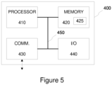
- Figure 5 illustrates a block diagram of some components of an apparatus 400 that may be employed to implement at least some of the operations described with references to the respective one of the lighting control apparatus 140 or the user apparatus 150.
- the apparatus 400 comprises a processor 410 and a memory 420.
- the memory 420 may store data and computer program code 425.
- the apparatus 400 may further comprise communication means 430 for wired or wireless communication with other apparatuses, where the communication means 430 may comprise the respective one of the communication portions 123-k, 143-j, 143-k.
- the apparatus 400 may further comprise user I/O (input/output) components 440 that may be arranged, together with the processor 410 and a portion of the computer program code 425, to provide a user interface for receiving input from a user and/or providing output to the user.
- the user I/O components may include user input means, such as one or more keys or buttons, a keyboard, a touchscreen or a touchpad, etc.
- the user I/O components may include output means, such as a display or a touchscreen.
- the components of the apparatus 400 are communicatively coupled to each other via a bus 450 that enables transfer of data and control information between the components.
- the memory 420 and a portion of the computer program code 425 stored therein may be further arranged, with the processor 410, to cause the apparatus 400 to perform at least some aspects of controlling operation of the respective one of the lighting control apparatus 140 or the user apparatus 150.
- the processor 410 is configured to read from and write to the memory 420.
- the processor 410 is depicted as a respective single component, it may be implemented as respective one or more separate processing components.
- the memory 420 is depicted as a respective single component, it may be implemented as respective one or more separate components, some or all of which may be integrated/removable and/or may provide permanent / semi-permanent/ dynamic/cached storage.
- the computer program code 425 may comprise computer-executable instructions that implement at least some aspects of controlling operation of the respective one of the lighting control apparatus 140 or the user apparatus 150 when loaded into the processor 410.
- the computer program code 425 may include a computer program consisting of one or more sequences of one or more instructions.
- the processor 410 is able to load and execute the computer program by reading the one or more sequences of one or more instructions included therein from the memory 420.
- the one or more sequences of one or more instructions may be configured to, when executed by the processor 410, cause the apparatus 400 to perform at least some aspects of controlling operation of the lighting control apparatus 140 or the user apparatus 150.
- the apparatus 400 may comprise at least one processor 410 and at least one memory 420 including the computer program code 425 for one or more programs, the at least one memory 420 and the computer program code 425 configured to, with the at least one processor 410, cause the apparatus 400 to perform at least some aspects of controlling operation of the lighting control apparatus 140 or the user apparatus 150.
- the computer program code 425 may be provided e.g. a computer program product comprising at least one computer-readable non-transitory medium having the computer program code 425 stored thereon, which computer program code 425, when executed by the processor 410 causes the apparatus 400 to perform at least some aspects of controlling operation of the lighting control apparatus 140 or the user apparatus 150.
- the computer-readable non-transitory medium may comprise a memory device or a record medium that tangibly embodies the computer program.
- the computer program may be provided as a signal configured to reliably transfer the computer program.
- references(s) to a processor herein should not be understood to encompass only programmable processors, but also dedicated circuits such as field-programmable gate arrays (FPGA), application specific circuits (ASIC), signal processors, etc.
- FPGA field-programmable gate arrays
- ASIC application specific circuits
- signal processors etc.
Landscapes
- Engineering & Computer Science (AREA)
- Computer Networks & Wireless Communication (AREA)
- Circuit Arrangement For Electric Light Sources In General (AREA)
Priority Applications (1)
| Application Number | Priority Date | Filing Date | Title |
|---|---|---|---|
| EP22202060.4A EP4358651A1 (fr) | 2022-10-18 | 2022-10-18 | Commande d'éclairage |
Applications Claiming Priority (1)
| Application Number | Priority Date | Filing Date | Title |
|---|---|---|---|
| EP22202060.4A EP4358651A1 (fr) | 2022-10-18 | 2022-10-18 | Commande d'éclairage |
Publications (1)
| Publication Number | Publication Date |
|---|---|
| EP4358651A1 true EP4358651A1 (fr) | 2024-04-24 |
Family
ID=89846420
Family Applications (1)
| Application Number | Title | Priority Date | Filing Date |
|---|---|---|---|
| EP22202060.4A Pending EP4358651A1 (fr) | 2022-10-18 | 2022-10-18 | Commande d'éclairage |
Country Status (1)
| Country | Link |
|---|---|
| EP (1) | EP4358651A1 (fr) |
Citations (3)
| Publication number | Priority date | Publication date | Assignee | Title |
|---|---|---|---|---|
| WO2014024078A1 (fr) * | 2012-08-07 | 2014-02-13 | Koninklijke Philips N.V. | Commande d'éclairage minutée |
| US20160092198A1 (en) * | 2014-09-29 | 2016-03-31 | Koninklijke Philips N.V. | Systems and methods for lighting control |
| EP3820255A1 (fr) * | 2019-11-05 | 2021-05-12 | Helvar Oy Ab | Commande d'éclairage à configuration automatique |
-
2022
- 2022-10-18 EP EP22202060.4A patent/EP4358651A1/fr active Pending
Patent Citations (3)
| Publication number | Priority date | Publication date | Assignee | Title |
|---|---|---|---|---|
| WO2014024078A1 (fr) * | 2012-08-07 | 2014-02-13 | Koninklijke Philips N.V. | Commande d'éclairage minutée |
| US20160092198A1 (en) * | 2014-09-29 | 2016-03-31 | Koninklijke Philips N.V. | Systems and methods for lighting control |
| EP3820255A1 (fr) * | 2019-11-05 | 2021-05-12 | Helvar Oy Ab | Commande d'éclairage à configuration automatique |
Similar Documents
| Publication | Publication Date | Title |
|---|---|---|
| US10009983B2 (en) | Networking groups of photocontrol devices | |
| US11949532B2 (en) | Camera-based commissioning | |
| US9510430B2 (en) | Illumination regulating system in synchronization with AC power frequency and method using the same | |
| US10477653B2 (en) | Notification lighting control | |
| US10076013B2 (en) | Portable light source | |
| US10659157B2 (en) | Apparatus and method for registering visible light communication device and combining visible light communication signal and wireless communication signal | |
| JP2017041408A (ja) | 照明制御システム、およびこれに用いられる照明制御装置 | |
| US10306737B2 (en) | Method for configuring a device in a lighting system | |
| US9549453B2 (en) | Remotely programming a photocontrol device | |
| US20190045347A1 (en) | Lighting system, setting device, and pairing method for lighting system | |
| US10149360B2 (en) | Lighting control system, lighting control method, control device, and control method | |
| KR102325326B1 (ko) | 조명 장치를 제어하기 위한 장치 및 방법 | |
| EP4358651A1 (fr) | Commande d'éclairage | |
| JP6830240B2 (ja) | 照明器具又は照明制御装置の制御方法及び端末装置 | |
| KR101903909B1 (ko) | 무선네트워크 기반 조명노드의 자동 설정 방법 | |
| JP2021158102A (ja) | 照明デバイスの到来角コミッショニング | |
| EP3863375A1 (fr) | Commande d'éclairage | |
| EP4203624A1 (fr) | Commande d'éclairage | |
| EP4203623A1 (fr) | Commande d'éclairage | |
| KR102605039B1 (ko) | 스마트 조명 제어 시스템 | |
| EP4344262A1 (fr) | Partage d'informations environnementales par l'intermédiaire d'un réseau de commande d'éclairage | |
| CN112703823B (zh) | 照明装置的快速调试 | |
| KR20140060270A (ko) | 조명장치 등록 및 제어를 위한 장치 및 방법 |
Legal Events
| Date | Code | Title | Description |
|---|---|---|---|
| PUAI | Public reference made under article 153(3) epc to a published international application that has entered the european phase |
Free format text: ORIGINAL CODE: 0009012 |
|
| STAA | Information on the status of an ep patent application or granted ep patent |
Free format text: STATUS: THE APPLICATION HAS BEEN PUBLISHED |
|
| AK | Designated contracting states |
Kind code of ref document: A1 Designated state(s): AL AT BE BG CH CY CZ DE DK EE ES FI FR GB GR HR HU IE IS IT LI LT LU LV MC ME MK MT NL NO PL PT RO RS SE SI SK SM TR |