EP4358318A1 - Electrical connector arrangement - Google Patents
Electrical connector arrangement Download PDFInfo
- Publication number
- EP4358318A1 EP4358318A1 EP22202924.1A EP22202924A EP4358318A1 EP 4358318 A1 EP4358318 A1 EP 4358318A1 EP 22202924 A EP22202924 A EP 22202924A EP 4358318 A1 EP4358318 A1 EP 4358318A1
- Authority
- EP
- European Patent Office
- Prior art keywords
- connector
- locking
- cam
- peg
- connector arrangement
- Prior art date
- Legal status (The legal status is an assumption and is not a legal conclusion. Google has not performed a legal analysis and makes no representation as to the accuracy of the status listed.)
- Pending
Links
Images


Classifications
-
- H—ELECTRICITY
- H01—ELECTRIC ELEMENTS
- H01R—ELECTRICALLY-CONDUCTIVE CONNECTIONS; STRUCTURAL ASSOCIATIONS OF A PLURALITY OF MUTUALLY-INSULATED ELECTRICAL CONNECTING ELEMENTS; COUPLING DEVICES; CURRENT COLLECTORS
- H01R13/00—Details of coupling devices of the kinds covered by groups H01R12/70 or H01R24/00 - H01R33/00
- H01R13/62—Means for facilitating engagement or disengagement of coupling parts or for holding them in engagement
- H01R13/629—Additional means for facilitating engagement or disengagement of coupling parts, e.g. aligning or guiding means, levers, gas pressure electrical locking indicators, manufacturing tolerances
- H01R13/62905—Additional means for facilitating engagement or disengagement of coupling parts, e.g. aligning or guiding means, levers, gas pressure electrical locking indicators, manufacturing tolerances comprising a camming member
- H01R13/62911—U-shaped sliding element
-
- H—ELECTRICITY
- H01—ELECTRIC ELEMENTS
- H01R—ELECTRICALLY-CONDUCTIVE CONNECTIONS; STRUCTURAL ASSOCIATIONS OF A PLURALITY OF MUTUALLY-INSULATED ELECTRICAL CONNECTING ELEMENTS; COUPLING DEVICES; CURRENT COLLECTORS
- H01R13/00—Details of coupling devices of the kinds covered by groups H01R12/70 or H01R24/00 - H01R33/00
- H01R13/62—Means for facilitating engagement or disengagement of coupling parts or for holding them in engagement
- H01R13/629—Additional means for facilitating engagement or disengagement of coupling parts, e.g. aligning or guiding means, levers, gas pressure electrical locking indicators, manufacturing tolerances
- H01R13/62905—Additional means for facilitating engagement or disengagement of coupling parts, e.g. aligning or guiding means, levers, gas pressure electrical locking indicators, manufacturing tolerances comprising a camming member
- H01R13/62922—Pair of camming plates
Definitions
- This invention generally relates to an electrical connector arrangement. Particularly it relates to an electrical connector arrangement comprising two connectors, respectively connector housings, and a mate assist device for facilitating mating and un-mating of the two connectors in a reliable and safe manner.
- a common "lever-type” electrical connector includes an assembly of a first connector (connector housing) and a second connector. To mate the connectors together, the assembly has an actuating or assist lever mounted for pivoting on the first connector and pivoting of the lever causes the first and second connectors to shift between unmated and fully mated configurations.
- the actuating lever and the second connector typically have a cam groove and a cam follower arrangement for drawing the second connector into mating condition with the first connector in response to pivoting of the lever.
- Such connectors are commonly used in the automotive industry.
- a connector arrangement which comprises first and second connector housings that are mateable with each other with the help of a mate assist device in form of a mate assist slider that is arranged movable on one of the connector housings in a linear direction perpendicular to the mating direction.
- the slider comprises cam slots that are adapted to interact with corresponding cam followers in form of cam pegs on the respective other connector housing. Upon movement of the slider the cam pegs interact with the cam slot, thereby moving the two connector housings relative to each other in mating direction.
- Prior art document WO 2010/070395 describes an alternative mate assist device in form of a rotatable lever.
- the lever is arranged pivotable on one of the connector housings and comprises a cam slot that is adapted to interact with a corresponding cam peg arranged on the respective other connector housing.
- the cam peg interacts with the cam slot and the two connector housings are moved relative to each other.
- the interacting principle of cam slot and cam peg is essentially the same as with linearly arranged sliders, as the skilled person understands. From the art, also designs are known, where the connector arrangement comprises a linear slider as well as a rotary lever, whereby the slider is moved by means of a rotation of the lever.
- mate assist devices are commonly used in connector arrangements that require the connection of multiple electrical terminals, which requires correspondingly a relatively large mating force.
- the common design feature is the interaction of a cam surface on the slider or lever that is mounted on one of the connector housings and a corresponding cam follower or cam peg arranged on the respective other connector housing.
- the un-mating process with the help of such mate assist devices is realized with a smooth, uninterrupted movement of the respective device. While this might be generally acceptable and desirable for many low voltage connectors it may have the disadvantage, that electrical arcing may occur upon disconnection of the electrical contact terminals, which typically takes place half way between the mechanical un-mating process.
- the time between disconnection of the control pins and the subsequent following disconnection of the power terminals might not be sufficient to safely cut-off the power supply, in particular upon a quick movement of the mate assist device.
- a connector arrangement comprising a first connector and a corresponding counter connector adapted to mate with the first connector.
- the arrangement comprises a mate assist device, movably mountable on the first connector, comprising at least one cam slot adapted to cooperate with a corresponding cam follower respectively cam peg arranged on the counter connector, such that upon movement of the mate assist device, the connector and counter connector are moved relative to each other.
- the mate assist device may for example be a linear slider or a rotary lever or a mixture of both, whereby for example the rotary lever is adapted to engage with the slider, such that a rotary movement of the lever leads to a linear movement of the slider.
- the mate assist device further comprises a locking feature, which is arranged to engage with a corresponding locking element provided on the counter connector upon partial un-mating of the connectors, to block a further movement of the mate assist device in un-mating direction.
- the feature allows to provide a two stage un-mating sequence, preferably without the necessity for additional parts or flexible features to the connector.
- the feature may be implemented by adding a blocking feature to one of the cam surfaces, on which a peg, such as a dedicated locking peg and/or a cam peg associated with the mate assist device, is stopped during the un-mating movement. This stopping of the un-mating movement slows the un-mating process, thereby enabling for example a secure cut-off of electrical power flowing through the contact terminals.
- the locking feature is provided in at least one cam slot of the mate assist device.
- the mate assist device or devices may have one or more cam slots, to guide the relative movement of the two connector housings to be mated. It may also comprise a dedicated locking cam slot, that is basically only intended to implement the locking feature without necessarily contributing to the mating process.
- the locking feature may be implemented in any cam slot, whether it is a dedicated locking cam slot or a cam slot to assist in the mating process. It is also possible that more than one locking feature is provided.
- the locking feature comprises a step provided in the cam surface of the cam slot adapted to engage with the locking element.
- the cam slots associated with such mate assist devices have smooth cam surfaces, to facilitate the mating and un-mating process, respectively the use of the mate assist device.
- the locking feature may be provided in form of a step, which comes into contact with the locking element, so that the otherwise smooth operation of the mate assist device is intentionally interrupted.
- the step and/or the corresponding locking element may be shaped, such that the un-mating process may be continued by applying a stronger force onto the mate assist device by the user, to overcome the locking step. It is also contemplated that the locking may be overcome by manually disengaging the locking element from the locking step. Any kind of release functionality is feasible, as long as the un-mating is stopped or interrupted for sufficiently long time, to allow a safe cut-off of the electrical power transmitted through the connectors.
- the locking element is a locking peg.
- the locking peg is advantageously adapted such that it cooperates with the locking feature, as for example with a locking step or similar provided in the cam surface of the cam slot.
- the locking peg is a cam peg.
- the locking peg may at the same time serve as a cam peg, respectively is a cam peg, that is adapted to interact with the cam surface, to realize the respective mating movement of the two connector housings upon actuation of the mate assist device.
- the mate assist device is provided in form of a slider or a lever, the cam peg interacting with the cam slot may at the same time serve as a locking peg, that engages with the locking step at some point during the un-mating process, like for example in the middle of the un-mating process.
- the mate assist device is a linear slider or a rotary lever.
- the mate assist device is a linear slider and the first connector comprises guide means to allow a linear movement of the slider perpendicular to the mating direction.
- the first connector should comprise structural guide means, which allow a movement of the slider relative to the first connector.
- the guide means are adapted such that the slider can transfer forces in mating or un-mating direction onto the first connector housing.
- the cam peg and the cam slot interact such that a force is created in mating or un-mating direction, depending on the direction the slider is moved. Since the slider is coupled to the first housing by means of the guide means, this force is transferred to the first housing, thereby moving the first housing relative to the second housing in mating, respectively un-mating direction.
- the locking feature is arranged such that upon engagement of the locking feature, connector and counter connector are still electrically coupled.
- the un-mating process should be interrupted by the engagement of the locking feature, to give for example a control device sufficient time to safely interrupt (cut-off) the electrical power transferred through the connector housings. Only after the safe cut-off of electrical power, the electrical power terminals of the two connector housings should come out of contact with each other, so that no electrical sparking can occur.
- the locking feature is adapted to allow a manual release thereof. This may be achieved by many different means, and is preferably achievable without the need for dedicated tools.
- the locking engagement is designed such that it can be overcome by applying an additional force onto the mate assist device. This necessary force is sufficient to interrupt the un-mating process of the user to allow a cut-off of the electrical power.
- the locking feature is adapted to allow a manual release by pulling the first connector in un-mating direction.
- the user has to rearrange his grip on the connector arrangement as he typically needs to let go of the mate assist device in order to grasp the connector housings. This requires the necessary additional one or two seconds for safe cut-off of the electrical power, and nevertheless still provides for a convenient and quick un-mating process.
- the locking feature is a step provided in a cam surface of a cam slot
- the locking element is a locking peg abutting the step upon locking, and wherein a release space is provided below the step, that is dimensioned to receive the locking peg therein.
- the cam slot is advantageously provided with a dedicated space for receiving the locking peg, after the locking peg comes into contact with the step. Thereby, it is possible to dispose the mate assist device in a corresponding direction, so that the step comes out of engagement with the locking peg.
- the locking peg has a locking contour adapted to the contour of the step.
- a locking contour adapted to the contour of the step.
- a release of the locking may be achieved by applying a sufficient force onto the mate assist device or it is also possible, to provide locking contours that make it impossible to disengage the locking by simply applying sufficient force.
- the mate assist device is a slider comprising two parallel actuating arms connected by a common web, each arm comprising at least two cam slots, a first of the slots being adapted to cooperate with a corresponding cam peg provided on the counter connector, such that a linear movement of the slider moves the connector and counter connector relative to each other; and a second of the cam slots being a locking slot adapted to cooperate with a locking peg that is different from the cam peg.
- Each of the arms has two cam slots, wherein one is particularly dedicated to achieve the desired mate assist functionality, described above in detail.
- the second cam slots are dedicated locking slots comprising for example a locking step.
- the connector arrangement is a high voltage connector arrangement, adapted to transfer voltages of 24V or more. While the present disclosure is useful and advantageous for any kind of electrical connector arrangement it is particularly useful for high-voltage applications. In such applications electrical sparking may occur that is potentially dangerous for the technical equipment connected by means of the connector arrangement and in particular to the user un-mating the two connector housings.
- the electrical power is switched off, before the power contact terminals of the two connector housings are moved out of contact with each other during the un-mating process.
- the connector arrangement comprises control pins and electrical power terminals, wherein the control pins are arranged such that during the un-mating process the control pins are disengaged before the electrical power terminals are disengaged, and wherein preferably, upon disengagement of the control pins, the electrical power flowing through the power terminals is cut-off.
- control pins are arranged such that during the un-mating process the control pins are disengaged before the electrical power terminals are disengaged, and wherein preferably, upon disengagement of the control pins, the electrical power flowing through the power terminals is cut-off.
- the control mechanism switches off the electrical power transferred by means of the power terminals of the connectors.
- the contact pins and electrical power terminals are designed, respectively adapted such that during an un-mating movement of the two connector housings, first the contact pins come out of contact with each other and only afterwards, the electrical power terminals.
- the control pins are designed, such that they are no longer in contact with each other once the locking feature interrupts the un-mating movement.
- Figure 1 shows a connector 10, also denoted as counter connector, on the left-hand side and the mate assist device 20 in form of a slider on the right hand side in a three-dimensional, schematic view.
- the connector 10 comprises a mating face 16 for mating with a corresponding connector 30, also denoted as first connector.
- the connector 30 is shown in mated condition in figure 3 .
- the connector 10 comprises a connection end 18 to receive e.g. electrical cables, such as for example a high voltage cable and/or signal cables and similar.
- This slider has two parallel actuating arms 21 and 22, that are connected by a common web 23.
- the slider has essentially a U-shape.
- the slider is symmetrical, so that the features visible on actuating arm 22 are likewise present on the actuating arm 21.
- the actuating arm 22 (and also the arm 21, as both are symmetrical) is provided with two cam slots 24 and 25.
- a flexible blocking wing 28 is provided, that prevents that the slider once mounted to the connector housing 30 can be accidentally removed from the housing. This feature is commonly known, so that is refrained from providing more details thereof.
- the cam slot 25 is provided with a locking feature in form of a locking step 26.
- the cam/locking peg 14 slides along the cam slot 25 until it reaches the step 26. Due to the shapes of cam 25 respectively locking peg 14 and step 26, the movement of the slider 20 is blocked and thus also the un-mating process is blocked. Due to this interruption of the un-mating process, it is possible for suitable control electronics to cut-off the electrical power transferred by the connectors before the respective electrical power terminals of the connectors come out of contact with each other. Thereby, any undesired electrical discharge or sparking can be prevented.
- Figure 2 shows the slider 20 of figure 1 in a side view.
- Figure 3 shows a connector arrangement 1 in accordance with the invention and in particular the un-mating process between connector 10 (counter connector) and connector 30 (first connector) in six illustrations A) to F).
- Figure 3 (A) shows the connector arrangement 1 in a fully mated condition.
- the slider 20 is mounted to connector 30 by means of guide means 31 and 32, that are provided in form of guide rails to guide the linear movement of slider 20 relative to connector 30.
- Locking peg 14 is arranged in cam slot 25 and cam peg 12 is arranged in cam slot 24 of slider 20.
- the pegs 12 and 14 will interact with the cam surfaces of cam slots 24 and 25 and thereby transfer a force onto the two connector housings, such that the two connectors will be moved relative to each other in the un-mating direction, which is perpendicular to the movement direction of slider 20.
- the slider 20 was moved a little bit to the left until the pegs 12 , 14 come into contact with the inclined cam surfaces of the respective cam slots 24, 25. In this position the two connectors 10, 30 are still in the fully mated condition.
- Figures 4A-C show three alternative configurations of locking peg 14 and step 26.
- the locking peg 14' has a rounded contact surface and the step 26' has a correspondingly shaped rounded contact surface. This configuration allows a release of the locking by strongly pulling the slider 20 to the left.
- Figure 4B shows another embodiment, where locking peg 14 and step 26 have a rectangular locking contour or contact surface such that also a strong pulling force to the slider 20 will not overcome the locking engagement. Instead, in the configuration shown in figure 4B it is necessary to pull connector housing 10 and the corresponding slider 20 upwards in un-mating direction, so that the locking peg 14 is moved in release space 27 and out of engagement with locking step 26. This configuration corresponds to the one shown exemplary in figure 3 .
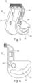
- FIG. 5 shows an alternative mate assist device 50 in form of a rotatable lever 50.
- the lever 50 comprises two actuating arms 51, 52 connected by a common web 53.
- Each actuating arm comprises a cam slot, of which only cam slot 55 of arm 52 is visible due to the perspective shown.
- the cam slots are provided with locking steps 56 similar to the locking step 26 of the embodiment described in connection with figures 1 to 4 .
- Each arm is provided with only one cam slot and the skilled person will recognize, that the principles of the present invention can be realized also with such a configuration.
- As the working principles of mate assist devices of the lever type are generally known to the skilled person, it is refrained from giving a more detailed explanation thereof.
- a locking respectively cam peg will interact with the cam slot 55 upon rotation of the lever 50. Since the lever is hinged to one of the connector housings by means of a pivot opening 59, and the peg is arranged on the respective other connector, a movement of lever 50 will lead to a relative movement of the two connector housings in mating, respectively un-mating direction. The respective cam peg will travel through the cam slot 55 until it comes into contact with step 56, whereby the un-mating movement of lever 50 is interrupted. In the shown configuration, it is possible to overcome this engagement by applying additional force to lever 50.
- Figure 6 shows the lever 50 of figure 5 in a side view.
Landscapes
- Details Of Connecting Devices For Male And Female Coupling (AREA)
Abstract
Description
- This invention generally relates to an electrical connector arrangement. Particularly it relates to an electrical connector arrangement comprising two connectors, respectively connector housings, and a mate assist device for facilitating mating and un-mating of the two connectors in a reliable and safe manner.
- A common "lever-type" electrical connector includes an assembly of a first connector (connector housing) and a second connector. To mate the connectors together, the assembly has an actuating or assist lever mounted for pivoting on the first connector and pivoting of the lever causes the first and second connectors to shift between unmated and fully mated configurations. Usually, the actuating lever and the second connector typically have a cam groove and a cam follower arrangement for drawing the second connector into mating condition with the first connector in response to pivoting of the lever. Such connectors are commonly used in the automotive industry.
- From
WO 2010/076592 a connector arrangement is unknown, which comprises first and second connector housings that are mateable with each other with the help of a mate assist device in form of a mate assist slider that is arranged movable on one of the connector housings in a linear direction perpendicular to the mating direction. The slider comprises cam slots that are adapted to interact with corresponding cam followers in form of cam pegs on the respective other connector housing. Upon movement of the slider the cam pegs interact with the cam slot, thereby moving the two connector housings relative to each other in mating direction. - Prior art document
WO 2010/070395 describes an alternative mate assist device in form of a rotatable lever. The lever is arranged pivotable on one of the connector housings and comprises a cam slot that is adapted to interact with a corresponding cam peg arranged on the respective other connector housing. Upon rotating of the lever, the cam peg interacts with the cam slot and the two connector housings are moved relative to each other. The interacting principle of cam slot and cam peg is essentially the same as with linearly arranged sliders, as the skilled person understands. From the art, also designs are known, where the connector arrangement comprises a linear slider as well as a rotary lever, whereby the slider is moved by means of a rotation of the lever. - These kind of mate assist devices are commonly used in connector arrangements that require the connection of multiple electrical terminals, which requires correspondingly a relatively large mating force. The common design feature is the interaction of a cam surface on the slider or lever that is mounted on one of the connector housings and a corresponding cam follower or cam peg arranged on the respective other connector housing. Typically, the un-mating process with the help of such mate assist devices is realized with a smooth, uninterrupted movement of the respective device. While this might be generally acceptable and desirable for many low voltage connectors it may have the disadvantage, that electrical arcing may occur upon disconnection of the electrical contact terminals, which typically takes place half way between the mechanical un-mating process. This is in particular a safety problem for high-voltage connectors, such as in applications requiring 24V or more. With such applications, it is desirable that the power is cut-off, before the electrical contact terminals are disengaged. To achieve this, it is known to provide the connector arrangement with additional electrical control pins, that are arranged, such that upon un-mating of the connectors, first the control pins are disconnected and the electrical power terminals only afterwards. The disconnection of the control pins sends a signal that leads to cut-off of the electrical power, so that upon disconnection of the power terminals no electrical current is flowing between the terminals.
- As the mate assist devices are designed to allow a smooth and uninterrupted operation and mating and un-mating process, the time between disconnection of the control pins and the subsequent following disconnection of the power terminals might not be sufficient to safely cut-off the power supply, in particular upon a quick movement of the mate assist device.
- It is therefore an object of the present disclosure to improve the known connector arrangements and to provide a mate assist design that allows an improved un-mating process. It is in particular an object of the present disclosure to provide a connector arrangement with a mate assist device that improves the safety of the un-mating process in view of a current flowing between one or more electrical contact terminals.
- These and other objects, which will become apparent upon reading the following description, are solved by a connector arrangement according to claim 1.
- According to the present disclosure, a connector arrangement is provided, comprising a first connector and a corresponding counter connector adapted to mate with the first connector. The arrangement comprises a mate assist device, movably mountable on the first connector, comprising at least one cam slot adapted to cooperate with a corresponding cam follower respectively cam peg arranged on the counter connector, such that upon movement of the mate assist device, the connector and counter connector are moved relative to each other. The mate assist device may for example be a linear slider or a rotary lever or a mixture of both, whereby for example the rotary lever is adapted to engage with the slider, such that a rotary movement of the lever leads to a linear movement of the slider. The mate assist device further comprises a locking feature, which is arranged to engage with a corresponding locking element provided on the counter connector upon partial un-mating of the connectors, to block a further movement of the mate assist device in un-mating direction.
- This novel feature allows to provide a two stage un-mating sequence, preferably without the necessity for additional parts or flexible features to the connector. Generally, the feature may be implemented by adding a blocking feature to one of the cam surfaces, on which a peg, such as a dedicated locking peg and/or a cam peg associated with the mate assist device, is stopped during the un-mating movement. This stopping of the un-mating movement slows the un-mating process, thereby enabling for example a secure cut-off of electrical power flowing through the contact terminals.
- For a secure cut-off of the electrical power, it is often sufficient that the un-mating movement is hindered for a very short time, such as a second or even a fraction of a second. To overcome the locking feature, it might be for example sufficient to apply additional force, or it is also feasible that the user has to make an additional manual step, such as a pulling movement of one of the connectors in mating direction, which will be described in more detail below.
- In a preferred embodiment, the locking feature is provided in at least one cam slot of the mate assist device. The mate assist device or devices may have one or more cam slots, to guide the relative movement of the two connector housings to be mated. It may also comprise a dedicated locking cam slot, that is basically only intended to implement the locking feature without necessarily contributing to the mating process. The locking feature may be implemented in any cam slot, whether it is a dedicated locking cam slot or a cam slot to assist in the mating process. It is also possible that more than one locking feature is provided.
- In a preferred embodiment, the locking feature comprises a step provided in the cam surface of the cam slot adapted to engage with the locking element. Usually, the cam slots associated with such mate assist devices have smooth cam surfaces, to facilitate the mating and un-mating process, respectively the use of the mate assist device. The locking feature may be provided in form of a step, which comes into contact with the locking element, so that the otherwise smooth operation of the mate assist device is intentionally interrupted. The step and/or the corresponding locking element may be shaped, such that the un-mating process may be continued by applying a stronger force onto the mate assist device by the user, to overcome the locking step. It is also contemplated that the locking may be overcome by manually disengaging the locking element from the locking step. Any kind of release functionality is feasible, as long as the un-mating is stopped or interrupted for sufficiently long time, to allow a safe cut-off of the electrical power transmitted through the connectors.
- In another preferred embodiment, the locking element is a locking peg. The locking peg is advantageously adapted such that it cooperates with the locking feature, as for example with a locking step or similar provided in the cam surface of the cam slot. To this end, it maybe advantageous to provide the locking peg with dedicated locking surface that is designed to interact with the shape of the locking step.
- In another preferred embodiment, the locking peg is a cam peg. As will be understood by the skilled person, the locking peg may at the same time serve as a cam peg, respectively is a cam peg, that is adapted to interact with the cam surface, to realize the respective mating movement of the two connector housings upon actuation of the mate assist device. If for example, the mate assist device is provided in form of a slider or a lever, the cam peg interacting with the cam slot may at the same time serve as a locking peg, that engages with the locking step at some point during the un-mating process, like for example in the middle of the un-mating process.
- Preferably, the mate assist device is a linear slider or a rotary lever. These elements are well established in the art and the users are well acquainted with such kind of mate assist devices.
- Preferably, the mate assist device is a linear slider and the first connector comprises guide means to allow a linear movement of the slider perpendicular to the mating direction. If the mate assist device is for example a linear slider the first connector should comprise structural guide means, which allow a movement of the slider relative to the first connector. The guide means are adapted such that the slider can transfer forces in mating or un-mating direction onto the first connector housing. Thus, when the slider is moved and interacts with for example a cam peg provided on the second connector housing by means of a suitable cam slot, the cam peg and the cam slot interact such that a force is created in mating or un-mating direction, depending on the direction the slider is moved. Since the slider is coupled to the first housing by means of the guide means, this force is transferred to the first housing, thereby moving the first housing relative to the second housing in mating, respectively un-mating direction.
- Preferably, the locking feature is arranged such that upon engagement of the locking feature, connector and counter connector are still electrically coupled. As explained above, the un-mating process should be interrupted by the engagement of the locking feature, to give for example a control device sufficient time to safely interrupt (cut-off) the electrical power transferred through the connector housings. Only after the safe cut-off of electrical power, the electrical power terminals of the two connector housings should come out of contact with each other, so that no electrical sparking can occur.
- Further preferred, the locking feature is adapted to allow a manual release thereof. This may be achieved by many different means, and is preferably achievable without the need for dedicated tools. One possibility is for example that the locking engagement is designed such that it can be overcome by applying an additional force onto the mate assist device. This necessary force is sufficient to interrupt the un-mating process of the user to allow a cut-off of the electrical power.
- Preferably, the locking feature is adapted to allow a manual release by pulling the first connector in un-mating direction. In this way, the user has to rearrange his grip on the connector arrangement as he typically needs to let go of the mate assist device in order to grasp the connector housings. This requires the necessary additional one or two seconds for safe cut-off of the electrical power, and nevertheless still provides for a convenient and quick un-mating process.
- Preferably, the locking feature is a step provided in a cam surface of a cam slot, and the locking element is a locking peg abutting the step upon locking, and wherein a release space is provided below the step, that is dimensioned to receive the locking peg therein. The cam slot is advantageously provided with a dedicated space for receiving the locking peg, after the locking peg comes into contact with the step. Thereby, it is possible to dispose the mate assist device in a corresponding direction, so that the step comes out of engagement with the locking peg.
- Preferably, the locking peg has a locking contour adapted to the contour of the step. By using dedicated contours, respectively shapes of locking peg and step, it is possible to achieve a very reliable interruption of the un-mating process. At the same time, and for example depending on the respective application, it is also possible to form the contours such that a release of the locking may be achieved by applying a sufficient force onto the mate assist device or it is also possible, to provide locking contours that make it impossible to disengage the locking by simply applying sufficient force. In the latter case, it may be for example necessary to manually release locking peg and step or to move the mate assist device in a direction different from the un-mating direction. It is thereby possible to control the time required for the user to overcome the locking to make sure, that the required time is sufficient for a safe cut-off of the electrical power.
- Preferably, the mate assist device is a slider comprising two parallel actuating arms connected by a common web, each arm comprising at least two cam slots, a first of the slots being adapted to cooperate with a corresponding cam peg provided on the counter connector, such that a linear movement of the slider moves the connector and counter connector relative to each other; and a second of the cam slots being a locking slot adapted to cooperate with a locking peg that is different from the cam peg. By providing the slider with two parallel actuating arms, a particularly rigid and strong construction can be achieved. Each of the arms has two cam slots, wherein one is particularly dedicated to achieve the desired mate assist functionality, described above in detail. The second cam slots are dedicated locking slots comprising for example a locking step. By using a dedicated cam slot for the mating and un-mating assistance and a dedicated cam slot for the inventive interruption of the un-mating process, each slot can be designed optimally for its dedicated purpose.
- Preferably, the connector arrangement is a high voltage connector arrangement, adapted to transfer voltages of 24V or more. While the present disclosure is useful and advantageous for any kind of electrical connector arrangement it is particularly useful for high-voltage applications. In such applications electrical sparking may occur that is potentially dangerous for the technical equipment connected by means of the connector arrangement and in particular to the user un-mating the two connector housings. Here, it is particularly advantageous that the electrical power is switched off, before the power contact terminals of the two connector housings are moved out of contact with each other during the un-mating process.
- Preferably, the connector arrangement comprises control pins and electrical power terminals, wherein the control pins are arranged such that during the un-mating process the control pins are disengaged before the electrical power terminals are disengaged, and wherein preferably, upon disengagement of the control pins, the electrical power flowing through the power terminals is cut-off. The skilled person understands, that there are various technical ways to detect an un-mating process of two connector housings. One particularly reliable way is to provide control pins to the connector housings that are for example in electrical contact in the mated condition. Upon un-mating, the two control pins are disengaged, respectively disconnected from each other, which can be easily detected by a suitable control mechanism. Once the disconnection of the two control pins is detected, the control mechanism switches off the electrical power transferred by means of the power terminals of the connectors. To this end, it is preferred, that the contact pins and electrical power terminals are designed, respectively adapted such that during an un-mating movement of the two connector housings, first the contact pins come out of contact with each other and only afterwards, the electrical power terminals. The skilled person will understand that such an arrangement is particularly useful with the present invention when the control pins are designed, such that they are no longer in contact with each other once the locking feature interrupts the un-mating movement.
- In the following, preferred embodiments of the invention are disclosed by reference to the accompanying figures, in which:
-
Fig. 1 shows a three-dimensional view of a connector housing and a mate assist device in form of a slider; -
Fig. 2 shows the mate assist device ofFig. 1 in a side view; -
Fig. 3 shows the un-mating process of a connector arrangement according to the invention; -
Fig. 4 shows detailed side views of three preferred embodiments of locking features; -
Fig. 5 shows a three-dimensional view of a mate assist device in form of a rotary lever; -
Fig. 6 shows the mate assist device ofFig. 5 in a side view. - In the following, preferred embodiments of the invention are described in detail with respect to the figures.
-
Figure 1 shows aconnector 10, also denoted as counter connector, on the left-hand side and the mate assistdevice 20 in form of a slider on the right hand side in a three-dimensional, schematic view. Theconnector 10 comprises amating face 16 for mating with a correspondingconnector 30, also denoted as first connector. Theconnector 30 is shown in mated condition infigure 3 . On the opposite end of themating face 16 theconnector 10 comprises aconnection end 18 to receive e.g. electrical cables, such as for example a high voltage cable and/or signal cables and similar. On the housing side visible infigure 1 , one can see afirst cam peg 12 and asecond cam peg 14, which can also be denoted as lockingpeg 14. - This slider has two
parallel actuating arms common web 23. Thus, seen from a top view, the slider has essentially a U-shape. The slider is symmetrical, so that the features visible on actuatingarm 22 are likewise present on theactuating arm 21. The actuating arm 22 (and also thearm 21, as both are symmetrical) is provided with twocam slots flexible blocking wing 28 is provided, that prevents that the slider once mounted to theconnector housing 30 can be accidentally removed from the housing. This feature is commonly known, so that is refrained from providing more details thereof. - The
cam slot 25 is provided with a locking feature in form of a lockingstep 26. During the un-mating process the cam/lockingpeg 14 slides along thecam slot 25 until it reaches thestep 26. Due to the shapes ofcam 25 respectively lockingpeg 14 andstep 26, the movement of theslider 20 is blocked and thus also the un-mating process is blocked. Due to this interruption of the un-mating process, it is possible for suitable control electronics to cut-off the electrical power transferred by the connectors before the respective electrical power terminals of the connectors come out of contact with each other. Thereby, any undesired electrical discharge or sparking can be prevented. -
Figure 2 shows theslider 20 offigure 1 in a side view. -
Figure 3 shows a connector arrangement 1 in accordance with the invention and in particular the un-mating process between connector 10 (counter connector) and connector 30 (first connector) in six illustrations A) to F). -
Figure 3 (A) shows the connector arrangement 1 in a fully mated condition. Theslider 20 is mounted toconnector 30 by means of guide means 31 and 32, that are provided in form of guide rails to guide the linear movement ofslider 20 relative toconnector 30. Lockingpeg 14 is arranged incam slot 25 and cam peg 12 is arranged incam slot 24 ofslider 20. The skilled person will realize, that upon movement ofslider 20 to the left in the un-mating direction ofslider 20, thepegs cam slots slider 20. Infigure 3B theslider 20 was moved a little bit to the left until thepegs respective cam slots connectors - In
figure 3C theslider 20 is moved even farther to the left. Now, the cam pegs 12, 14 are in contact with the inclined cam surfaces of the respective cam slots, so that an upwards force is created between the connectors and in the shown scenario theconnector 30 is consequently moved upwards relative toconnector 10. - In
figure 3D the cam/lockingpeg 14 is engaged by the lockingstep 26 and theslider 20 cannot move farther to the left. Theconnector 30 is only partially unmated fromconnector 10. In this shown configuration, the electrical power terminals of the connector arrangement are still in electrical contact with each other. Since the un-mating process is interrupted or blocked a suitable control system may switch off the power supply to the connector arrangement. Alternatively, it is of course also possible that the operator manually switches off the power supply. - To release the engagement of locking
peg 14 andstep 26 in the shown embodiment, it is possible and necessary to pullconnector 30 together withslider 20 manually upwards, i.e. in the un-mating direction. As the skilled person will understand, this requires a rearrangement of the manual grasp of the user, thereby interrupting the un-mating process for a few seconds. Thecam slot 25 is provided with aspace 27, which allows the lockingpeg 14 to move downwards incam slot 25, thereby being released from the lockingstep 26. In the shown configuration infigure 3D it is now possible to complete the un-mating process by further pulling theslider 20 to the left in the figures. The lockingpeg 14 will interact with the inclined surface ofcam slot 25 to the right hand side ofstep 26, leading to an upwards motion ofconnector housing 30 in un-mating direction.Figure 3F shows the fully unmated condition. -
Figures 4A-C show three alternative configurations of lockingpeg 14 andstep 26. Infigure 4A , the locking peg 14' has a rounded contact surface and the step 26' has a correspondingly shaped rounded contact surface. This configuration allows a release of the locking by strongly pulling theslider 20 to the left. -
Figure 4B shows another embodiment, where lockingpeg 14 and step 26 have a rectangular locking contour or contact surface such that also a strong pulling force to theslider 20 will not overcome the locking engagement. Instead, in the configuration shown infigure 4B it is necessary to pullconnector housing 10 and the correspondingslider 20 upwards in un-mating direction, so that the lockingpeg 14 is moved inrelease space 27 and out of engagement with lockingstep 26. This configuration corresponds to the one shown exemplary infigure 3 . - In
figure 4C the locking contours ofpeg 14" and step 26" our such that also a manual upward movement ofconnector housing 10 is not possible. With this configuration it may for example be necessary to manually bend the actuatingarms slider 20 outwardly to release the engagement. -
Figure 5 shows an alternative mate assistdevice 50 in form of arotatable lever 50. Thelever 50 comprises two actuatingarms common web 53. Each actuating arm comprises a cam slot, of which onlycam slot 55 ofarm 52 is visible due to the perspective shown. The cam slots are provided with lockingsteps 56 similar to the lockingstep 26 of the embodiment described in connection withfigures 1 to 4 . Each arm is provided with only one cam slot and the skilled person will recognize, that the principles of the present invention can be realized also with such a configuration. As the working principles of mate assist devices of the lever type are generally known to the skilled person, it is refrained from giving a more detailed explanation thereof. - Generally speaking, the working principle is the same as with the slider 20: A locking respectively cam peg will interact with the
cam slot 55 upon rotation of thelever 50. Since the lever is hinged to one of the connector housings by means of apivot opening 59, and the peg is arranged on the respective other connector, a movement oflever 50 will lead to a relative movement of the two connector housings in mating, respectively un-mating direction. The respective cam peg will travel through thecam slot 55 until it comes into contact withstep 56, whereby the un-mating movement oflever 50 is interrupted. In the shown configuration, it is possible to overcome this engagement by applying additional force to lever 50. -
Figure 6 shows thelever 50 offigure 5 in a side view. -
- 1
- connector arrangement
- 10
- connector housing (counter connector)
- 12
- cam peg
- 14, 14', 14"
- cam/locking peg
- 16
- mating face
- 18
- connection end
- 20
- mate assist device (slider)
- 21, 22
- actuating arms
- 23
- web
- 24, 25
- cam slots
- 26, 26', 26"
- locking step
- 27
- release space
- 28
- blocking wing
- 30
- connector housing (first connector housing)
- 31, 32
- guide rails
- 50
- mate assist device (lever)
- 51, 52
- actuating arms
- 53
- web
- 55
- cam slot
- 56
- step
- 59
- pivot opening
Claims (15)
- Connector arrangement (1), comprising:a first connector (30) and a corresponding counter connector (10) adapted to mate with the first connector;a mate assist device (20; 50), movably mountable on the first connector (30), comprising at least one cam slot (24, 25; 55) adapted to cooperate with a corresponding cam peg (12, 14) arranged on the counter connector (10), such that upon movement of the mate assist device (20; 50), the connector and counter connector are moved relative to each other,characterized in that
the mate assist device (20; 50) further comprises a locking feature (26; 56), which is arranged to engage with a corresponding locking element (14) provided on the counter connector (10) upon partial un-mating of the connectors, to block a further movement of the mate assist device in un-mating direction. - The connector arrangement (1) according to claim 1, wherein the locking feature (26; 56) is provided in at least one cam slot (24; 55) of the mate assist device.
- The connector arrangement (1) according to the preceding claim, wherein the locking feature comprises a step (26; 56) provided in the cam surface of the cam slot (24; 55) adapted to engage with the locking element (14).
- The connector arrangement (1) according to any of the preceding claims, wherein the locking element is a locking peg (14).
- The connector arrangement (1) according to any of the preceding claims, wherein the locking peg (14) is a cam peg.
- The connector arrangement (1) according to any of the preceding claims, wherein the mate assist device (20) is a linear slider or a rotary lever (50).
- The connector arrangement (1) according to any of the preceding claims, wherein the mate assist device (20) is a linear slider and the first connector (30) comprises guide means (31, 32) to allow a linear movement of the slider (20) perpendicular to the mating direction.
- The connector arrangement (1) according to any of the preceding claims, wherein the locking feature (26; 56) is arranged such that upon engagement of the locking feature, connector and counter connector are still electrically coupled.
- The connector arrangement (1) according to any of the preceding claims, wherein the locking feature (26; 56) is adapted to allow a manual release thereof.
- The connector arrangement (1) according to the preceding claim, wherein the locking feature (26; 56) is adapted to a allow a manual release by pulling the first connector (30) in un-mating direction.
- The connector arrangement (1) according to any of the preceding claims, wherein the locking feature (26; 56) is a step provided in a cam surface of a cam slot, and the locking element (14) is a locking peg abutting the step upon locking, and wherein a release space (27) is provided below the step, that is dimensioned to receive the locking peg therein.
- The connector arrangement (1) according to the preceding claim, wherein the locking peg (14) has a locking contour adapted to the contour of the step (26; 56).
- The connector arrangement (1) according to any of the preceding claims, wherein the mate assist device is a slider (20) comprising two parallel actuating arms (21, 22) connected by a common web (23), each arm comprising at least two cam slots (24, 25), a first (24) of the slots being adapted to cooperate with a corresponding cam peg (12) provided on the counter connector (30), such that a linear movement of the slider moves the connector (10) and counter connector (30) relative to each other;
and a second (25) of the cam slots being a locking slot adapted to cooperate with a locking peg (14) that is different from the cam peg (12). - The connector arrangement (1) according to any of the preceding claims, wherein the connector arrangement is a high voltage connector arrangement, adapted to transfer voltages of 24V or more.
- The connector arrangement (1) according to any of the preceding claims, wherein the connector arrangement comprises control pins and electrical power terminals, wherein the control pins are arranged such that during the un-mating process the control pins are disengaged before the electrical power terminals are disengaged, and wherein preferably upon disengagement of the control pins, the electrical power flowing through the power terminals is cut-off.
Priority Applications (1)
| Application Number | Priority Date | Filing Date | Title |
|---|---|---|---|
| EP22202924.1A EP4358318A1 (en) | 2022-10-21 | 2022-10-21 | Electrical connector arrangement |
Applications Claiming Priority (1)
| Application Number | Priority Date | Filing Date | Title |
|---|---|---|---|
| EP22202924.1A EP4358318A1 (en) | 2022-10-21 | 2022-10-21 | Electrical connector arrangement |
Publications (1)
| Publication Number | Publication Date |
|---|---|
| EP4358318A1 true EP4358318A1 (en) | 2024-04-24 |
Family
ID=83902906
Family Applications (1)
| Application Number | Title | Priority Date | Filing Date |
|---|---|---|---|
| EP22202924.1A Pending EP4358318A1 (en) | 2022-10-21 | 2022-10-21 | Electrical connector arrangement |
Country Status (1)
| Country | Link |
|---|---|
| EP (1) | EP4358318A1 (en) |
Citations (4)
| Publication number | Priority date | Publication date | Assignee | Title |
|---|---|---|---|---|
| US5888080A (en) * | 1996-04-11 | 1999-03-30 | Yazaki Corporation | Low insertion pressure connector |
| EP0631347B1 (en) * | 1993-06-17 | 1999-04-07 | The Whitaker Corporation | Electrical connector having improved sliding latch |
| WO2010070395A1 (en) | 2008-12-18 | 2010-06-24 | Fci | Connector assembly with mate-assist device |
| US20220255264A1 (en) * | 2021-02-11 | 2022-08-11 | TE Connectivity Services Gmbh | Spring loaded self-ejecting connector |
-
2022
- 2022-10-21 EP EP22202924.1A patent/EP4358318A1/en active Pending
Patent Citations (4)
| Publication number | Priority date | Publication date | Assignee | Title |
|---|---|---|---|---|
| EP0631347B1 (en) * | 1993-06-17 | 1999-04-07 | The Whitaker Corporation | Electrical connector having improved sliding latch |
| US5888080A (en) * | 1996-04-11 | 1999-03-30 | Yazaki Corporation | Low insertion pressure connector |
| WO2010070395A1 (en) | 2008-12-18 | 2010-06-24 | Fci | Connector assembly with mate-assist device |
| US20220255264A1 (en) * | 2021-02-11 | 2022-08-11 | TE Connectivity Services Gmbh | Spring loaded self-ejecting connector |
Similar Documents
| Publication | Publication Date | Title |
|---|---|---|
| CN102132465B (en) | Electrical connector components and a method for unmating the same | |
| EP2639807B1 (en) | Power source circuit cutoff device | |
| EP1093191B1 (en) | Locking mechanism in connector | |
| EP1100160B1 (en) | Electrical connector assembly with improved camming system | |
| US6325648B1 (en) | Electrical connector assembly with complementary lever assist and terminal delay | |
| CN110571567B (en) | Staged release electrical connector assembly | |
| EP1956686B1 (en) | Connector with an elastic slider | |
| WO2010015889A1 (en) | Electrical connector assembly, an electrical device comprising the same and a method for mating the same | |
| EP2774160B1 (en) | An auxiliary contact block | |
| US11996651B2 (en) | Safely separating plug connector part | |
| EP3163687A1 (en) | Connector having locking of the lever for facilitating the connection | |
| CN103782362B (en) | For setting up and/or the switching device of connection of disconnection of plug and mated plug | |
| CN102598178B (en) | For the drive unit of multi-position switch equipment | |
| EP4016579A1 (en) | Electric switching apparatus | |
| KR101508501B1 (en) | Connecter assembly | |
| CA2832065C (en) | Internally switched female receptacle or connector with plug-latching safety interlock | |
| CN106716755A (en) | Insertion-extraction-mechanism | |
| CN114256770A (en) | Position indicating device for electrical switchgear | |
| EP3252881A1 (en) | Electrical connector with a slider | |
| CN220492322U (en) | Connector handle convenient to dismouting | |
| CN1096697C (en) | Switch device | |
| CN105186930B (en) | With the module mechanically and electrically locked for terminal module | |
| JP7469344B2 (en) | connector | |
| CN103563184B (en) | For setting up and disconnect the device of the connection between plug-in unit and cooperation plug-in unit | |
| EP4340138A1 (en) | Secured high power connector assembly and process of assembly |
Legal Events
| Date | Code | Title | Description |
|---|---|---|---|
| PUAI | Public reference made under article 153(3) epc to a published international application that has entered the european phase |
Free format text: ORIGINAL CODE: 0009012 |
|
| STAA | Information on the status of an ep patent application or granted ep patent |
Free format text: STATUS: THE APPLICATION HAS BEEN PUBLISHED |
|
| AK | Designated contracting states |
Kind code of ref document: A1 Designated state(s): AL AT BE BG CH CY CZ DE DK EE ES FI FR GB GR HR HU IE IS IT LI LT LU LV MC ME MK MT NL NO PL PT RO RS SE SI SK SM TR |
|
| RAP1 | Party data changed (applicant data changed or rights of an application transferred) |
Owner name: APTIV TECHNOLOGIES AG |
|
| RAP3 | Party data changed (applicant data changed or rights of an application transferred) |
Owner name: APTIV TECHNOLOGIES AG |
|
| STAA | Information on the status of an ep patent application or granted ep patent |
Free format text: STATUS: REQUEST FOR EXAMINATION WAS MADE |
|
| 17P | Request for examination filed |
Effective date: 20241022 |
|
| RBV | Designated contracting states (corrected) |
Designated state(s): AL AT BE BG CH CY CZ DE DK EE ES FI FR GB GR HR HU IE IS IT LI LT LU LV MC ME MK MT NL NO PL PT RO RS SE SI SK SM TR |