EP4358296A1 - Antenna and antenna system - Google Patents
Antenna and antenna system Download PDFInfo
- Publication number
- EP4358296A1 EP4358296A1 EP22202634.6A EP22202634A EP4358296A1 EP 4358296 A1 EP4358296 A1 EP 4358296A1 EP 22202634 A EP22202634 A EP 22202634A EP 4358296 A1 EP4358296 A1 EP 4358296A1
- Authority
- EP
- European Patent Office
- Prior art keywords
- antenna
- monocone
- feed
- reflecting surface
- additional
- Prior art date
- Legal status (The legal status is an assumption and is not a legal conclusion. Google has not performed a legal analysis and makes no representation as to the accuracy of the status listed.)
- Granted
Links
Images

Classifications
-
- H—ELECTRICITY
- H01—ELECTRIC ELEMENTS
- H01Q—ANTENNAS, i.e. RADIO AERIALS
- H01Q19/00—Combinations of primary active antenna elements and units with secondary devices, e.g. with quasi-optical devices, for giving the antenna a desired directional characteristic
- H01Q19/10—Combinations of primary active antenna elements and units with secondary devices, e.g. with quasi-optical devices, for giving the antenna a desired directional characteristic using reflecting surfaces
- H01Q19/12—Combinations of primary active antenna elements and units with secondary devices, e.g. with quasi-optical devices, for giving the antenna a desired directional characteristic using reflecting surfaces wherein the surfaces are concave
- H01Q19/13—Combinations of primary active antenna elements and units with secondary devices, e.g. with quasi-optical devices, for giving the antenna a desired directional characteristic using reflecting surfaces wherein the surfaces are concave the primary radiating source being a single radiating element, e.g. a dipole, a slot, a waveguide termination
- H01Q19/132—Horn reflector antennas; Off-set feeding
-
- H—ELECTRICITY
- H01—ELECTRIC ELEMENTS
- H01Q—ANTENNAS, i.e. RADIO AERIALS
- H01Q1/00—Details of, or arrangements associated with, antennas
- H01Q1/36—Structural form of radiating elements, e.g. cone, spiral, umbrella; Particular materials used therewith
-
- H—ELECTRICITY
- H01—ELECTRIC ELEMENTS
- H01Q—ANTENNAS, i.e. RADIO AERIALS
- H01Q1/00—Details of, or arrangements associated with, antennas
- H01Q1/50—Structural association of antennas with earthing switches, lead-in devices or lightning protectors
-
- H—ELECTRICITY
- H01—ELECTRIC ELEMENTS
- H01Q—ANTENNAS, i.e. RADIO AERIALS
- H01Q13/00—Waveguide horns or mouths; Slot antennas; Leaky-waveguide antennas; Equivalent structures causing radiation along the transmission path of a guided wave
- H01Q13/02—Waveguide horns
-
- H—ELECTRICITY
- H01—ELECTRIC ELEMENTS
- H01Q—ANTENNAS, i.e. RADIO AERIALS
- H01Q15/00—Devices for reflection, refraction, diffraction or polarisation of waves radiated from an antenna, e.g. quasi-optical devices
- H01Q15/14—Reflecting surfaces; Equivalent structures
- H01Q15/16—Reflecting surfaces; Equivalent structures curved in two dimensions [2D], e.g. paraboloidal
-
- H—ELECTRICITY
- H01—ELECTRIC ELEMENTS
- H01Q—ANTENNAS, i.e. RADIO AERIALS
- H01Q19/00—Combinations of primary active antenna elements and units with secondary devices, e.g. with quasi-optical devices, for giving the antenna a desired directional characteristic
- H01Q19/10—Combinations of primary active antenna elements and units with secondary devices, e.g. with quasi-optical devices, for giving the antenna a desired directional characteristic using reflecting surfaces
- H01Q19/12—Combinations of primary active antenna elements and units with secondary devices, e.g. with quasi-optical devices, for giving the antenna a desired directional characteristic using reflecting surfaces wherein the surfaces are concave
-
- H—ELECTRICITY
- H01—ELECTRIC ELEMENTS
- H01Q—ANTENNAS, i.e. RADIO AERIALS
- H01Q19/00—Combinations of primary active antenna elements and units with secondary devices, e.g. with quasi-optical devices, for giving the antenna a desired directional characteristic
- H01Q19/10—Combinations of primary active antenna elements and units with secondary devices, e.g. with quasi-optical devices, for giving the antenna a desired directional characteristic using reflecting surfaces
- H01Q19/12—Combinations of primary active antenna elements and units with secondary devices, e.g. with quasi-optical devices, for giving the antenna a desired directional characteristic using reflecting surfaces wherein the surfaces are concave
- H01Q19/13—Combinations of primary active antenna elements and units with secondary devices, e.g. with quasi-optical devices, for giving the antenna a desired directional characteristic using reflecting surfaces wherein the surfaces are concave the primary radiating source being a single radiating element, e.g. a dipole, a slot, a waveguide termination
-
- H—ELECTRICITY
- H01—ELECTRIC ELEMENTS
- H01Q—ANTENNAS, i.e. RADIO AERIALS
- H01Q21/00—Antenna arrays or systems
- H01Q21/06—Arrays of individually energised antenna units similarly polarised and spaced apart
- H01Q21/061—Two dimensional planar arrays
-
- H—ELECTRICITY
- H01—ELECTRIC ELEMENTS
- H01Q—ANTENNAS, i.e. RADIO AERIALS
- H01Q21/00—Antenna arrays or systems
- H01Q21/06—Arrays of individually energised antenna units similarly polarised and spaced apart
- H01Q21/20—Arrays of individually energised antenna units similarly polarised and spaced apart the units being spaced along or adjacent to a curvilinear path
- H01Q21/205—Arrays of individually energised antenna units similarly polarised and spaced apart the units being spaced along or adjacent to a curvilinear path providing an omnidirectional coverage
-
- H—ELECTRICITY
- H01—ELECTRIC ELEMENTS
- H01Q—ANTENNAS, i.e. RADIO AERIALS
- H01Q21/00—Antenna arrays or systems
- H01Q21/28—Combinations of substantially independent non-interacting antenna units or systems
-
- H—ELECTRICITY
- H01—ELECTRIC ELEMENTS
- H01Q—ANTENNAS, i.e. RADIO AERIALS
- H01Q3/00—Arrangements for changing or varying the orientation or the shape of the directional pattern of the waves radiated from an antenna or antenna system
- H01Q3/24—Arrangements for changing or varying the orientation or the shape of the directional pattern of the waves radiated from an antenna or antenna system varying the orientation by switching energy from one active radiating element to another, e.g. for beam switching
-
- H—ELECTRICITY
- H01—ELECTRIC ELEMENTS
- H01Q—ANTENNAS, i.e. RADIO AERIALS
- H01Q5/00—Arrangements for simultaneous operation of antennas on two or more different wavebands, e.g. dual-band or multi-band arrangements
- H01Q5/30—Arrangements for providing operation on different wavebands
- H01Q5/307—Individual or coupled radiating elements, each element being fed in an unspecified way
-
- H—ELECTRICITY
- H01—ELECTRIC ELEMENTS
- H01Q—ANTENNAS, i.e. RADIO AERIALS
- H01Q9/00—Electrically-short antennas having dimensions not more than twice the operating wavelength and consisting of conductive active radiating elements
- H01Q9/04—Resonant antennas
- H01Q9/30—Resonant antennas with feed to end of elongated active element, e.g. unipole
- H01Q9/40—Element having extended radiating surface
-
- H—ELECTRICITY
- H01—ELECTRIC ELEMENTS
- H01Q—ANTENNAS, i.e. RADIO AERIALS
- H01Q1/00—Details of, or arrangements associated with, antennas
- H01Q1/12—Supports; Mounting means
- H01Q1/22—Supports; Mounting means by structural association with other equipment or articles
- H01Q1/24—Supports; Mounting means by structural association with other equipment or articles with receiving set
- H01Q1/241—Supports; Mounting means by structural association with other equipment or articles with receiving set used in mobile communications, e.g. GSM
- H01Q1/246—Supports; Mounting means by structural association with other equipment or articles with receiving set used in mobile communications, e.g. GSM specially adapted for base stations
-
- H—ELECTRICITY
- H01—ELECTRIC ELEMENTS
- H01Q—ANTENNAS, i.e. RADIO AERIALS
- H01Q5/00—Arrangements for simultaneous operation of antennas on two or more different wavebands, e.g. dual-band or multi-band arrangements
- H01Q5/20—Arrangements for simultaneous operation of antennas on two or more different wavebands, e.g. dual-band or multi-band arrangements characterised by the operating wavebands
- H01Q5/25—Ultra-wideband [UWB] systems, e.g. multiple resonance systems; Pulse systems
-
- H—ELECTRICITY
- H01—ELECTRIC ELEMENTS
- H01Q—ANTENNAS, i.e. RADIO AERIALS
- H01Q9/00—Electrically-short antennas having dimensions not more than twice the operating wavelength and consisting of conductive active radiating elements
- H01Q9/04—Resonant antennas
- H01Q9/30—Resonant antennas with feed to end of elongated active element, e.g. unipole
- H01Q9/32—Vertical arrangement of element
Definitions
- the invention relates to an antenna and an antenna system.
- US 2016/0006114 A1 relates to methods and systems for low-profile or hidden antennas, and for installation and use of such antennas in particular locations, such as surfaces of roadways, pavements, walls, and/or ceilings.
- An example antenna system comprises a ground conductor configured to provide a ground plane for the antenna system, where the ground conductor comprises a recess, a monocone arranged in the recess of the ground conductor, and a conductive coupling between the monocone and the ground conductor to ground the monocone.
- the ground conductor comprises a recess, a monocone arranged in the recess of the ground conductor, and a conductive coupling between the monocone and the ground conductor to ground the monocone.
- an antenna comprises a monocone feed for inputting an input signal and/or outputting an output signal, and a reflecting surface comprising a parabolic shape for transmitting the input signal as an electromagnetic output wave and/or receiving an electromagnetic input wave as the output signal.
- a monocone feed for inputting an input signal and/or outputting an output signal
- a reflecting surface comprising a parabolic shape for transmitting the input signal as an electromagnetic output wave and/or receiving an electromagnetic input wave as the output signal.
- the parabolic shape comprises or is a two-dimensional parabolic shape.
- the reflecting surface is independent of frequency or wavelength, respectively, thereby increasing flexibility, and thus also efficiency.
- the reflecting surface is sandwiched between two planar surfaces.
- a cavity can be formed, wherein the monocone feed is located inside said cavity, thereby providing a kind of cavity antenna especially without the typical disadvantage of a narrow bandwidth.
- the monocone feed is placed at a focal line of the reflecting surface.
- an in-phase arrival of all reflections from a plane wave can be ensured.
- the monocone feed is offset from a focal line and/or a focal point of the reflecting surface.
- the antenna can be designed in accordance with a desired phase of arrival in an efficient manner.
- the reflecting surface is arranged with respect to the monocone feed such that all reflections from a plane wave to the corresponding center of the monocone feed at the respective focal point have the same path length.
- all reflections arrive in phase.
- the antenna comprises or is a wideband and/or directional antenna.
- said antenna can be operational up to 20 GHz, thereby further increasing flexibility.
- the antenna comprises or is a lightweight and/or low-profile antenna.
- the antenna comprises or is a lightweight and/or low-profile antenna.
- about 70 per cent reduction in physical volume in comparison with conventional antennas can be achieved, which leads to an increased flexibility.
- the antenna further comprises at least one further monocone feed for inputting the input signal and/or outputting the output signal and/or for inputting a further input signal and/or outputting a further output signal, and at least one further reflecting surface each comprising a further parabolic shape for transmitting the input signal as the electromagnetic output wave and/or receiving the electromagnetic input wave as the output signal and/or for transmitting the further input signal as a further electromagnetic output wave and/or receiving a further electromagnetic input wave as the further output signal.
- said antenna can be used with respect to different directions in a particularly efficient and accurate manner especially at the same time and without the need of moving said antenna.
- the monocone feed, the reflecting surface, the at least one further monocone feed, and the at least one further reflecting surface are arranged to form a directional array, especially a switched directional array.
- error and drive times can be reduced especially in Time Difference of Arrival (TDoA) systems.
- the monocone feed, the reflecting surface, the at least one further monocone feed, and the at least one further reflecting surface are arranged in a circular manner.
- complexity can be reduced, thereby increasing efficiency.
- the at least one further monocone feed are three further monocone feeds and the at least one further reflecting surface are three further reflecting surfaces, wherein the monocone feed and the three further monocone feeds substantially form the corners of an imaginary square.
- said antenna can be employed with respect to four major directions of interest in an efficient and accurate manner.
- the antenna further comprises at least one object, preferably at least one metallic object, more preferably at least one grounded metallic object, arranged in the vicinity of the reflecting surface especially for directing the electromagnetic output wave and/or the electromagnetic input wave.
- at least one object preferably at least one metallic object, more preferably at least one grounded metallic object, arranged in the vicinity of the reflecting surface especially for directing the electromagnetic output wave and/or the electromagnetic input wave.
- directional characteristic of said antenna can efficiently be adapted.
- an antenna system comprises an antenna according to the first aspect of the invention or any of its preferred implementation forms, respectively, and at least one additional monocone feed or at least one additional antenna.
- the antenna is arranged underneath, especially underneath a ground plane of, the at least one additional monocone feed or the at least one additional antenna.
- wideband capabilities can be provided, thereby ensuring a high flexibility, efficiency and accuracy. Further advantageously, performance, especially a radiation pattern, of said antenna system does not suffer when a flat metal surface is placed directly above or below said antenna system.
- the at least one additional antenna comprises or is at least one antenna according to the first aspect of the invention or any of its preferred implementation forms, respectively.
- the antenna and the at least one additional monocone feed are arranged such that the respective feeding points of the antenna and the at least one additional monocone feed are substantially oriented in the same direction.
- the antenna and the at least one additional antenna are arranged such that the respective feeding points of the antenna and the at least one additional antenna are substantially oriented in the same direction.
- complexity can be reduced, thereby increasing efficiency.
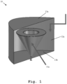
- FIG. 1 an exemplary embodiment 10 of an antenna in the sense of the invention is illustrated.
- Said antenna 10 comprises a monocone feed 11a for inputting an input signal and/or outputting an output signal, and a reflecting surface 12a comprising a parabolic shape for transmitting the input signal as an electromagnetic output wave and/or receiving an electromagnetic input wave as the output signal.
- the parabolic shape is a two-dimensional parabolic shape. Additionally, the reflecting surface 12a is sandwiched between two planar surfaces 13a, 13b.
- the reflecting surface 12 and said two planar surfaces 13a, 13b especially form a cavity.
- the above-mentioned monocone feed 11a is located inside said cavity.
- Fig. 2 depicting a top view of the antenna 10 of Fig. 1
- the monocone feed 11a is placed at a focal line 14 of the reflecting surface 12a.
- the above-mentioned planar surfaces 13a, 13b are substantially perpendicular to said focal line 14.
- substantially perpendicular is especially to be understood as an angle between 80 degrees and 100 degrees, preferably between 85 degrees and 95 degrees, more preferably between 88 degrees and 92 degrees, most preferably between 89.5 degrees and 90.5 degrees.
- the monocone feed 11a can be offset from a focal line, such as the above-mentioned focal line 14, and/or a focal point of the reflecting surface 12a.
- offset is especially to be understood as deviating from said focal line and/or said focal point of the reflecting surface 12a not more than 20 per cent, preferably 10 per cent, more preferably 5 per cent, most preferably 1 per cent, of the corresponding smallest or largest diameter of the monocone feed 11a.
- the reflecting surface 12a is arranged with respect to the monocone feed 11a such that all reflections from a plane wave, exemplarily illustrated by an incoming planar far-field 15, to the corresponding center, exemplarily being equivalent to the focal line 14, of the monocone feed 11a at the respective focal point have the same path length.
- all reflections advantageously arrive in phase especially due to said configuration.
- the antenna 10 can be implemented as a wideband and/or directional antenna. Additionally or alternatively, the antenna 10 can be implemented as a lightweight and/or low-profile antenna.
- wideband is especially to be understood as a multi-octave frequency bandwidth.
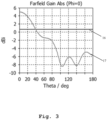
- FIG. 3 illustrates a comparison of the directional characteristic 16 of an monocone antenna with the directional characteristic 17 of an inventive antenna such as the antenna 10 of Fig. 1 or Fig. 2 , respectively.
- an antenna in the sense of the invention is used for base-station estimation and/or spectrum and mobile network monitoring and/or critical infrastructure monitoring. Additionally or alternatively, such an inventive antenna can be used in a switched directional array especially to reduce error and drive times in TDoA (Time Difference of Arrival) systems.
- TDoA Time Difference of Arrival
- an antenna in the sense of the invention is advantageously low cost, much smaller, exemplarily 70 per cent reduction in physical volume, and wideband, exemplarily operational up to 20 GHz.
- reflecting surface 12a is especially independent of frequency or wavelength, respectively.
- the above-mentioned monocone feed 11a is extremely wideband. As a further advantage, inventively, this results in an antenna that is both directional and wideband with little performance degradation, for instance, when placed on top of large metal surfaces.
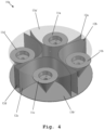
- FIG. 4 a further exemplary embodiment 10a of an inventive antenna, exemplarily being based on the antenna 10 of Fig. 1 or Fig. 2 , respectively, is illustrated.
- Said antenna 10a further comprises at least one further monocone feed, exemplarily three further monocone feeds 11b, 11c, 11d for inputting the input signal and/or outputting the output signal and/or for inputting a further input signal and/or outputting a further output signal, and at least one further reflecting surface, exemplarily three further reflecting surfaces 12b, 12c, 12d, each comprising a further parabolic shape for transmitting the input signal as the electromagnetic output wave and/or receiving the electromagnetic input wave as the output signal and/or for transmitting the further input signal as a further electromagnetic output wave and/or receiving a further electromagnetic input wave as the further output signal.
- the monocone feed 11a, the reflecting surface 12a, the at least one further monocone feed, exemplarily the three further monocone feeds 11b, 11c, 11d, and the at least one further reflecting surface, exemplarily the three further reflecting surfaces 12b, 12c, 12d, are arranged to form a directional array, especially a switched directional array.
- the monocone feed 11a, the reflecting surface 12a, the at least one further monocone feed, exemplarily the three further monocone feeds 11b, 11c, 11d, and the at least one further reflecting surface, exemplarily the three further reflecting surfaces 12b, 12c, 12d, are arranged in a circular manner.
- planar surfaces 13a', 13b' are of circular shape and/or of the same size.
- the monocone feed 11a and the three further monocone feeds 11b, 11c, 11d substantially form the corners of an imaginary square.
- an angle between two neighboring ones of said monocone feeds 11a, 11b, 11c, 11d is between 80 degrees and 100 degrees, preferably between 85 degrees and 95 degrees, more preferably between 88 degrees and 92 degrees, most preferably between 89.5 degrees and 90.5 degrees.
- the antenna 10 or 10a further comprises at least one object, preferably at least one metallic object, more preferably at least one grounded metallic object, arranged in the vicinity of the reflecting surface 12a or the further reflecting surfaces 12b, 12c, 12d, respectively, especially for directing the electromagnetic output wave and/or the electromagnetic input wave or the further electromagnetic output wave and/or the further electromagnetic input wave, respectively.
- said vicinity may preferably refer to the corresponding volume of the above-mentioned cavity.
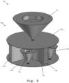
- FIG. 5 depicts an exemplary embodiment 20 of an inventive antenna system.
- Said antenna system 20 comprises an antenna in the sense of the invention, exemplarily the antenna 10a of Fig. 4 , and at least one additional monocone feed, exemplarily the additional monocone feed 21.
- the antenna 10a is arranged underneath, especially underneath a ground plane of, the additional monocone feed 21.
- the antenna 10a and the additional monocone feed 21 are arranged such that the respective feeding points of the antenna 10a and the additional monocone feed 21 are substantially oriented in the same direction.
- the respective apexes of the corresponding cone-shaped monocone feeds substantially point in the same direction.
- the term "substantially” is especially to be understood as deviating not more than 10 degrees, preferably 5 degrees, more preferably 2 degrees, most preferably 0.5 degrees, from a certain direction.
- the feeding point of the additional monocone 21 is located at the center of the circular-shaped surface 13a' or 13b', respectively.
- feeding point of the additional monocone 21 can be offset from the center of the circular-shaped surface 13a' or 13b', respectively.
- offset is especially to be understood as deviating from said center not more than 20 per cent, preferably 10 per cent, more preferably 5 per cent, most preferably 1 per cent, of the corresponding diameter of the circular-shaped surface 13a' or 13b', respectively.
Landscapes
- Physics & Mathematics (AREA)
- Electromagnetism (AREA)
- Aerials With Secondary Devices (AREA)
Abstract
Description
- The invention relates to an antenna and an antenna system.
- Generally, in times of an increasing number of communication applications providing wireless connectivity possibilities, there is a growing need of an antenna and an antenna system for performing measurements with respect to such applications in order to verify their correct functioning in an efficient and accurate manner, whereby a high flexibility is ensured due to wideband capabilities of said antenna or antenna system, respectively.
-
US 2016/0006114 A1 relates to methods and systems for low-profile or hidden antennas, and for installation and use of such antennas in particular locations, such as surfaces of roadways, pavements, walls, and/or ceilings. An example antenna system comprises a ground conductor configured to provide a ground plane for the antenna system, where the ground conductor comprises a recess, a monocone arranged in the recess of the ground conductor, and a conductive coupling between the monocone and the ground conductor to ground the monocone. However, in accordance with said document or the corresponding configuration, respectively, wideband capabilities cannot be provided, which disadvantageously leads to a limited flexibility, thereby also reducing efficiency and accuracy. - Accordingly, there is the object to provide an antenna and an antenna system in order to allow for performing measurements, especially measurements regarding wireless connectivity capabilities, in a flexible manner, thereby ensuring a high accuracy and efficiency of the measurement.
- This object is solved by the features of claim 1 for an antenna and the features of
claim 14 for an antenna system. The dependent claims contain further developments. - According to a first aspect of the invention, an antenna is provided. Said antenna comprises a monocone feed for inputting an input signal and/or outputting an output signal, and a reflecting surface comprising a parabolic shape for transmitting the input signal as an electromagnetic output wave and/or receiving an electromagnetic input wave as the output signal. Advantageously, wideband capabilities can be provided, thereby ensuring a high flexibility, efficiency and accuracy. Further advantageously, performance, especially a radiation pattern, of said antenna does not suffer when a flat metal surface is placed directly above or below said antenna.
- According to a first preferred implementation form of the first aspect of the invention, the parabolic shape comprises or is a two-dimensional parabolic shape. Advantageously, for instance, the reflecting surface is independent of frequency or wavelength, respectively, thereby increasing flexibility, and thus also efficiency.
- According to a second preferred implementation form of the first aspect of the invention, the reflecting surface is sandwiched between two planar surfaces. Advantageously, for example, a cavity can be formed, wherein the monocone feed is located inside said cavity, thereby providing a kind of cavity antenna especially without the typical disadvantage of a narrow bandwidth.
- According to a further preferred implementation form of the first aspect of the invention, the monocone feed is placed at a focal line of the reflecting surface. Advantageously, for instance, an in-phase arrival of all reflections from a plane wave can be ensured.
- According to a further preferred implementation form of the first aspect of the invention, the monocone feed is offset from a focal line and/or a focal point of the reflecting surface. Advantageously, for example, the antenna can be designed in accordance with a desired phase of arrival in an efficient manner.
- According to a further preferred implementation form of the first aspect of the invention, the reflecting surface is arranged with respect to the monocone feed such that all reflections from a plane wave to the corresponding center of the monocone feed at the respective focal point have the same path length. Advantageously, for instance, all reflections arrive in phase.
- According to a further preferred implementation form of the first aspect of the invention, the antenna comprises or is a wideband and/or directional antenna. Advantageously, for example, said antenna can be operational up to 20 GHz, thereby further increasing flexibility.
- According to a further preferred implementation form of the first aspect of the invention, the antenna comprises or is a lightweight and/or low-profile antenna. Advantageously, for instance, about 70 per cent reduction in physical volume in comparison with conventional antennas can be achieved, which leads to an increased flexibility.
- According to a further preferred implementation form of the first aspect of the invention, the antenna further comprises at least one further monocone feed for inputting the input signal and/or outputting the output signal and/or for inputting a further input signal and/or outputting a further output signal, and at least one further reflecting surface each comprising a further parabolic shape for transmitting the input signal as the electromagnetic output wave and/or receiving the electromagnetic input wave as the output signal and/or for transmitting the further input signal as a further electromagnetic output wave and/or receiving a further electromagnetic input wave as the further output signal. Advantageously, for example, said antenna can be used with respect to different directions in a particularly efficient and accurate manner especially at the same time and without the need of moving said antenna.
- According to a further preferred implementation form of the first aspect of the invention, the monocone feed, the reflecting surface, the at least one further monocone feed, and the at least one further reflecting surface are arranged to form a directional array, especially a switched directional array. Advantageously, for instance, error and drive times can be reduced especially in Time Difference of Arrival (TDoA) systems.
- According to a further preferred implementation form of the first aspect of the invention, the monocone feed, the reflecting surface, the at least one further monocone feed, and the at least one further reflecting surface are arranged in a circular manner. Advantageously, for example, complexity can be reduced, thereby increasing efficiency.
- According to a further preferred implementation form of the first aspect of the invention, the at least one further monocone feed are three further monocone feeds and the at least one further reflecting surface are three further reflecting surfaces, wherein the monocone feed and the three further monocone feeds substantially form the corners of an imaginary square. Advantageously, for instance, said antenna can be employed with respect to four major directions of interest in an efficient and accurate manner.
- According to a further preferred implementation form of the first aspect of the invention, the antenna further comprises at least one object, preferably at least one metallic object, more preferably at least one grounded metallic object, arranged in the vicinity of the reflecting surface especially for directing the electromagnetic output wave and/or the electromagnetic input wave. Advantageously, for example, directional characteristic of said antenna can efficiently be adapted.
- According to a second aspect of the invention, an antenna system is provided. Said antenna system comprises an antenna according to the first aspect of the invention or any of its preferred implementation forms, respectively, and at least one additional monocone feed or at least one additional antenna. In this context, the antenna is arranged underneath, especially underneath a ground plane of, the at least one additional monocone feed or the at least one additional antenna. Advantageously, wideband capabilities can be provided, thereby ensuring a high flexibility, efficiency and accuracy. Further advantageously, performance, especially a radiation pattern, of said antenna system does not suffer when a flat metal surface is placed directly above or below said antenna system.
- According to a first preferred implementation form of the second aspect of the invention, the at least one additional antenna comprises or is at least one antenna according to the first aspect of the invention or any of its preferred implementation forms, respectively. In addition to this or as an alternative, the antenna and the at least one additional monocone feed are arranged such that the respective feeding points of the antenna and the at least one additional monocone feed are substantially oriented in the same direction. Alternatively, the antenna and the at least one additional antenna are arranged such that the respective feeding points of the antenna and the at least one additional antenna are substantially oriented in the same direction. Advantageously, for instance, complexity can be reduced, thereby increasing efficiency.
- Exemplary embodiments of the invention are now further explained with respect to the drawings by way of example only, and not for limitation. In the drawings:
- Fig. 1
- shows an exemplary embodiment of an inventive antenna;
- Fig. 2
- shows a top view of the exemplary embodiment according to
Fig. 1 ; - Fig. 3
- illustrates a comparison of a monocone antenna with an inventive antenna in the context of absolute far-field gain;
- Fig. 4
- shows a further exemplary embodiment of an inventive antenna; and
- Fig. 5
- shows an exemplary embodiment of an inventive antenna system.
- Firstly, with respect to
Fig. 1 anexemplary embodiment 10 of an antenna in the sense of the invention is illustrated. - Said
antenna 10 comprises amonocone feed 11a for inputting an input signal and/or outputting an output signal, and a reflectingsurface 12a comprising a parabolic shape for transmitting the input signal as an electromagnetic output wave and/or receiving an electromagnetic input wave as the output signal. - As it can further be seen from
Fig. 1 , the parabolic shape is a two-dimensional parabolic shape. Additionally, the reflectingsurface 12a is sandwiched between twoplanar surfaces - It is noted that the reflecting surface 12 and said two
planar surfaces monocone feed 11a is located inside said cavity. - Furthermore, in accordance with
Fig. 2 depicting a top view of theantenna 10 ofFig. 1 , themonocone feed 11a is placed at afocal line 14 of the reflectingsurface 12a. In this context, it is noted that the above-mentionedplanar surfaces focal line 14. - It is further noted that the term "substantially perpendicular" is especially to be understood as an angle between 80 degrees and 100 degrees, preferably between 85 degrees and 95 degrees, more preferably between 88 degrees and 92 degrees, most preferably between 89.5 degrees and 90.5 degrees.
- Moreover, especially as an alternative, the
monocone feed 11a can be offset from a focal line, such as the above-mentionedfocal line 14, and/or a focal point of the reflectingsurface 12a. - In this context, the term "offset" is especially to be understood as deviating from said focal line and/or said focal point of the reflecting
surface 12a not more than 20 per cent, preferably 10 per cent, more preferably 5 per cent, most preferably 1 per cent, of the corresponding smallest or largest diameter of themonocone feed 11a. - As it can further be seen from
Fig. 2 , the reflectingsurface 12a is arranged with respect to themonocone feed 11a such that all reflections from a plane wave, exemplarily illustrated by an incoming planar far-field 15, to the corresponding center, exemplarily being equivalent to thefocal line 14, of themonocone feed 11a at the respective focal point have the same path length. In this context, it is noted that all reflections advantageously arrive in phase especially due to said configuration. - It is noted that the
antenna 10 can be implemented as a wideband and/or directional antenna. Additionally or alternatively, theantenna 10 can be implemented as a lightweight and/or low-profile antenna. - In this context, the term "wideband" is especially to be understood as a multi-octave frequency bandwidth.
- With special respect to said directional antenna, it is noted that
Fig. 3 illustrates a comparison of the directional characteristic 16 of an monocone antenna with the directional characteristic 17 of an inventive antenna such as theantenna 10 ofFig. 1 orFig. 2 , respectively. - In general, it is noted that it might be particularly advantageous if an antenna in the sense of the invention is used for base-station estimation and/or spectrum and mobile network monitoring and/or critical infrastructure monitoring. Additionally or alternatively, such an inventive antenna can be used in a switched directional array especially to reduce error and drive times in TDoA (Time Difference of Arrival) systems.
- Especially in this context, an antenna in the sense of the invention is advantageously low cost, much smaller, exemplarily 70 per cent reduction in physical volume, and wideband, exemplarily operational up to 20 GHz.
- Furthermore, with respect to the above-mentioned reflecting
surface 12a, it is to be pointed out that said reflectingsurface 12a is especially independent of frequency or wavelength, respectively. It is further noted that the above-mentionedmonocone feed 11a is extremely wideband. As a further advantage, inventively, this results in an antenna that is both directional and wideband with little performance degradation, for instance, when placed on top of large metal surfaces. - Now, with respect to
Fig. 4 , a furtherexemplary embodiment 10a of an inventive antenna, exemplarily being based on theantenna 10 ofFig. 1 orFig. 2 , respectively, is illustrated. - Said
antenna 10a further comprises at least one further monocone feed, exemplarily three further monocone feeds 11b, 11c, 11d for inputting the input signal and/or outputting the output signal and/or for inputting a further input signal and/or outputting a further output signal, and at least one further reflecting surface, exemplarily three further reflectingsurfaces - It is noted that the explanations above, especially regarding the
monocone feed 11a and the reflectingsurface 12a, can analogously be applied for at least one, preferably each, of said further monocone feeds 11b, 11c, 11d and said further reflectingsurfaces - It is further noted that it might be particularly advantageous if the
monocone feed 11a, the reflectingsurface 12a, the at least one further monocone feed, exemplarily the three further monocone feeds 11b, 11c, 11d, and the at least one further reflecting surface, exemplarily the three further reflectingsurfaces - As it can further be seen from
Fig. 4 , themonocone feed 11a, the reflectingsurface 12a, the at least one further monocone feed, exemplarily the three further monocone feeds 11b, 11c, 11d, and the at least one further reflecting surface, exemplarily the three further reflectingsurfaces - In addition to this, the
planar surfaces 13a', 13b', to which the above-mentioned corresponding explanations especially apply in an analogous manner, are of circular shape and/or of the same size. - It is further noted that the
monocone feed 11a and the three further monocone feeds 11b, 11c, 11d substantially form the corners of an imaginary square. In other words, an angle between two neighboring ones of said monocone feeds 11a, 11b, 11c, 11d is between 80 degrees and 100 degrees, preferably between 85 degrees and 95 degrees, more preferably between 88 degrees and 92 degrees, most preferably between 89.5 degrees and 90.5 degrees. - With respect to the
antenna 10 ofFig. 1 orFig. 2 , respectively, and theantenna 10a ofFig. 4 , it is noted that it might be particularly advantageous if theantenna surface 12a or the further reflectingsurfaces - With respect to the above-mentioned vicinity, it is noted that said vicinity may preferably refer to the corresponding volume of the above-mentioned cavity.
- Finally,
Fig. 5 depicts anexemplary embodiment 20 of an inventive antenna system. - Said
antenna system 20 comprises an antenna in the sense of the invention, exemplarily theantenna 10a ofFig. 4 , and at least one additional monocone feed, exemplarily theadditional monocone feed 21. - In this context, the
antenna 10a is arranged underneath, especially underneath a ground plane of, theadditional monocone feed 21. - In this context, as it can further be seen from
Fig. 5 , theantenna 10a and theadditional monocone feed 21 are arranged such that the respective feeding points of theantenna 10a and theadditional monocone feed 21 are substantially oriented in the same direction. In other words, the respective apexes of the corresponding cone-shaped monocone feeds substantially point in the same direction. - In this context, the term "substantially" is especially to be understood as deviating not more than 10 degrees, preferably 5 degrees, more preferably 2 degrees, most preferably 0.5 degrees, from a certain direction.
- It is noted that it might be particularly advantageous if the feeding point of the
additional monocone 21 is located at the center of the circular-shapedsurface 13a' or 13b', respectively. - It is further noted that the feeding point of the
additional monocone 21 can be offset from the center of the circular-shapedsurface 13a' or 13b', respectively. - In this context, the term "offset" is especially to be understood as deviating from said center not more than 20 per cent, preferably 10 per cent, more preferably 5 per cent, most preferably 1 per cent, of the corresponding diameter of the circular-shaped
surface 13a' or 13b', respectively. - While various embodiments of the present invention have been described above, it should be understood that they have been presented by way of example only, and not limitation. Numerous changes to the disclosed embodiments can be made in accordance with the disclosure herein without departing from the spirit or scope of the invention. Thus, the breadth and scope of the present invention should not be limited by any of the above described embodiments. Rather, the scope of the invention should be defined in accordance with the following claims and their equivalents.
- Although the invention has been illustrated and described with respect to one or more implementations, equivalent alterations and modifications will occur to others skilled in the art upon the reading and understanding of this specification and the annexed drawings. In addition, while a particular feature of the invention may have been disclosed with respect to only one of several implementations, such feature may be combined with one or more other features of the other implementations as may be desired and advantageous for any given or particular application.
Claims (15)
- An antenna (10, 10a) comprising:a monocone feed (11a) for inputting an input signal and/or outputting an output signal, anda reflecting surface (12a) comprising a parabolic shape for transmitting the input signal as an electromagnetic output wave and/or receiving an electromagnetic input wave as the output signal.
- The antenna (10, 10a) according to claim 1,
wherein the parabolic shape comprises or is a two-dimensional parabolic shape. - The antenna (10, 10a) according to claim 1 or 2,
wherein the reflecting surface (12a) is sandwiched between two planar surfaces (13a, 13a', 13b, 13b'). - The antenna (10, 10a) according to any of the claims 1 to 3,
wherein the monocone feed (11a) is placed at a focal line (14) of the reflecting surface (12a). - The antenna (10, 10a) according to any of the claims 1 to 3,
wherein the monocone feed (11a) is offset from a focal line and/or a focal point of the reflecting surface (12a). - The antenna (10, 10a) according to any of the claims 1 to 5,
wherein the reflecting surface (12a) is arranged with respect to the monocone feed (11a) such that all reflections from a plane wave (15) to the corresponding center of the monocone feed (11a) at the respective focal point have the same path length. - The antenna (10, 10a) according to any of the claims 1 to 6,
wherein the antenna (10, 10a) comprises or is a wideband and/or directional antenna. - The antenna (10, 10a) according to any of the claims 1 to 7,
wherein the antenna (10, 10a) comprises or is a lightweight and/or low-profile antenna. - The antenna (10, 10a) according to any of the claims 1 to 8,
wherein the antenna (10, 10a) further comprises:at least one further monocone feed (11b, 11c, 11d) for inputting the input signal and/or outputting the output signal and/or for inputting a further input signal and/or outputting a further output signal, andat least one further reflecting surface (12b, 12c, 12d) each comprising a further parabolic shape for transmitting the input signal as the electromagnetic output wave and/or receiving the electromagnetic input wave as the output signal and/or for transmitting the further input signal as a further electromagnetic output wave and/or receiving a further electromagnetic input wave as the further output signal. - The antenna (10, 10a) according to claim 9,
wherein the monocone feed (11a), the reflecting surface (12a), the at least one further monocone feed (11b, 11c, 11d), and the at least one further reflecting surface (12b, 12c, 12d) are arranged to form a directional array, especially a switched directional array. - The antenna (10, 10a) according to claim 9 or 10,
wherein the monocone feed (11a), the reflecting surface (12a), the at least one further monocone feed (11b, 11c, 11d), and the at least one further reflecting surface (12b, 12c, 12d) are arranged in a circular manner. - The antenna (10, 10a) according to any of the claims 9 to 11,
wherein the at least one further monocone feed (11b, 11c, 11d) are three further monocone feeds (11b, 11c, 11d) and the at least one further reflecting surface (12b, 12c, 12d) are three further reflecting surfaces (12b, 12c, 12d), wherein the monocone feed (11a) and the three further monocone feeds (11b, 11c, 11d) substantially form the corners of an imaginary square. - The antenna (10, 10a) according to any of the claims 1 to 12,
wherein the antenna (10, 10a) further comprises at least one object, preferably at least one metallic object, more preferably at least one grounded metallic object, arranged in the vicinity of the reflecting surface (12a) especially for directing the electromagnetic output wave and/or the electromagnetic input wave. - An antenna system (20) comprising:an antenna (10, 10a) according to any of the claims 1 to 13, andat least one additional monocone feed (21) or at least one additional antenna,wherein the antenna (10, 10a) is arranged underneath, especially underneath a ground plane of, the at least one additional monocone feed (21) or the at least one additional antenna.
- The antenna system (20) according to claim 14,wherein the at least one additional antenna comprises or is at least one antenna (10, 10a) according to any of the claims 1 to 13, and/orwherein the antenna (10, 10a) and the at least one additional monocone feed (21) are arranged such that the respective feeding points of the antenna (10, 10a) and the at least one additional monocone feed (21) are substantially oriented in the same direction, orwherein the antenna (10, 10a) and the at least one additional antenna are arranged such that the respective feeding points of the antenna (10, 10a) and the at least one additional antenna are substantially oriented in the same direction.
Priority Applications (3)
| Application Number | Priority Date | Filing Date | Title |
|---|---|---|---|
| EP22202634.6A EP4358296B1 (en) | 2022-10-20 | 2022-10-20 | Antenna and antenna system |
| CN202311191587.4A CN117917814A (en) | 2022-10-20 | 2023-09-15 | Antennas and Antenna Systems |
| US18/371,916 US12646857B2 (en) | 2022-10-20 | 2023-09-22 | Antenna and antenna system |
Applications Claiming Priority (1)
| Application Number | Priority Date | Filing Date | Title |
|---|---|---|---|
| EP22202634.6A EP4358296B1 (en) | 2022-10-20 | 2022-10-20 | Antenna and antenna system |
Publications (2)
| Publication Number | Publication Date |
|---|---|
| EP4358296A1 true EP4358296A1 (en) | 2024-04-24 |
| EP4358296B1 EP4358296B1 (en) | 2025-12-03 |
Family
ID=83900028
Family Applications (1)
| Application Number | Title | Priority Date | Filing Date |
|---|---|---|---|
| EP22202634.6A Active EP4358296B1 (en) | 2022-10-20 | 2022-10-20 | Antenna and antenna system |
Country Status (3)
| Country | Link |
|---|---|
| US (1) | US12646857B2 (en) |
| EP (1) | EP4358296B1 (en) |
| CN (1) | CN117917814A (en) |
Families Citing this family (1)
| Publication number | Priority date | Publication date | Assignee | Title |
|---|---|---|---|---|
| EP4358296B1 (en) * | 2022-10-20 | 2025-12-03 | Rohde & Schwarz GmbH & Co. KG | Antenna and antenna system |
Citations (4)
| Publication number | Priority date | Publication date | Assignee | Title |
|---|---|---|---|---|
| US3009154A (en) * | 1957-09-05 | 1961-11-14 | Philco Corp | Directive antenna system |
| US6956534B2 (en) * | 2000-12-27 | 2005-10-18 | Cocomo Mb Communications, Inc. | Method and apparatus for improving antenna efficiency |
| US20160006114A1 (en) | 2014-07-03 | 2016-01-07 | Swisscom Ag | Low-profile antennas |
| CN114583458B (en) * | 2022-05-06 | 2022-07-15 | 南京容测检测技术有限公司 | Small reverberation chamber excitation antenna |
Family Cites Families (24)
| Publication number | Priority date | Publication date | Assignee | Title |
|---|---|---|---|---|
| GB885942A (en) | 1958-02-24 | 1962-01-03 | Fritz Karl Zapletal | A self-shifting change speed gear |
| GB1016741A (en) | 1961-10-03 | 1966-01-12 | Black Automatic Controls Ltd | Improvements in fluid control valves |
| SU974005A1 (en) | 1980-11-26 | 1982-11-15 | Предприятие П/Я А-7755 | Safety valve |
| US5038152A (en) * | 1990-05-17 | 1991-08-06 | Hughes Aircraft Company | Broad band omnidirectional monocone antenna |
| DE534263T1 (en) | 1991-09-20 | 1993-09-02 | L.G.L. Electronics S.P.A., Bergamo | SELF-REGULATING THREAD BRAKE FOR A WIFE DELIVERY DEVICE. |
| US5192827A (en) | 1991-12-19 | 1993-03-09 | The United States Of America As Represented By The Secretary Of The Army | Microwave projectile |
| IT1269821B (en) | 1994-05-23 | 1997-04-15 | Dar Spa | EQUIPMENT FOR THE REALIZATION OF TRANSLARYNGAL TRACHEOSTOMY |
| US6170457B1 (en) | 1998-09-01 | 2001-01-09 | Outboard Marine Corporation | Fuel injection engine having fuel spray deflector |
| US7006047B2 (en) * | 2003-01-24 | 2006-02-28 | Bae Systems Information And Electronic Systems Integration Inc. | Compact low RCS ultra-wide bandwidth conical monopole antenna |
| US20090047610A1 (en) | 2007-08-13 | 2009-02-19 | Yu-Shan Teng | Remote control linearly regulated fuel valve |
| US7921760B2 (en) | 2007-10-22 | 2011-04-12 | Jerome Benedict Tankersley | Compact gas block with rail interface |
| WO2015120417A2 (en) * | 2014-02-08 | 2015-08-13 | Smart Antenna Systems, Inc | Wideband antenna star array |
| IL232050A0 (en) | 2014-04-10 | 2014-08-31 | Amir Assa | Device and method for desalination |
| US9692136B2 (en) | 2014-04-28 | 2017-06-27 | Te Connectivity Corporation | Monocone antenna |
| US20160043472A1 (en) * | 2014-04-28 | 2016-02-11 | Tyco Electronics Corporation | Monocone antenna |
| US10050752B1 (en) * | 2015-02-06 | 2018-08-14 | Sprint Communications Company L.P. | Radial antenna for small cell with a null feature |
| US10651558B1 (en) | 2015-10-16 | 2020-05-12 | Lockheed Martin Corporation | Omni antennas |
| EP3285332B1 (en) * | 2016-08-19 | 2019-04-03 | Swisscom AG | Antenna system |
| US10177434B1 (en) * | 2016-12-23 | 2019-01-08 | X Development Llc | Parabolic reflector combined with phased array feed for long range communication |
| US12082971B2 (en) | 2019-01-16 | 2024-09-10 | Trophy Sas | Method for scanning material using an ultrasonic imaging probe |
| CN110197950B (en) | 2019-06-06 | 2024-01-02 | 昆山瀚德通信科技有限公司 | Dual polarized antenna |
| US12206173B1 (en) * | 2022-10-19 | 2025-01-21 | Rockwell Collins, Inc. | Dual mode omni / directional sectored array |
| EP4358296B1 (en) * | 2022-10-20 | 2025-12-03 | Rohde & Schwarz GmbH & Co. KG | Antenna and antenna system |
| EP4418461A1 (en) * | 2023-02-20 | 2024-08-21 | Rohde & Schwarz GmbH & Co. KG | Antenna and antenna array |
-
2022
- 2022-10-20 EP EP22202634.6A patent/EP4358296B1/en active Active
-
2023
- 2023-09-15 CN CN202311191587.4A patent/CN117917814A/en active Pending
- 2023-09-22 US US18/371,916 patent/US12646857B2/en active Active
Patent Citations (4)
| Publication number | Priority date | Publication date | Assignee | Title |
|---|---|---|---|---|
| US3009154A (en) * | 1957-09-05 | 1961-11-14 | Philco Corp | Directive antenna system |
| US6956534B2 (en) * | 2000-12-27 | 2005-10-18 | Cocomo Mb Communications, Inc. | Method and apparatus for improving antenna efficiency |
| US20160006114A1 (en) | 2014-07-03 | 2016-01-07 | Swisscom Ag | Low-profile antennas |
| CN114583458B (en) * | 2022-05-06 | 2022-07-15 | 南京容测检测技术有限公司 | Small reverberation chamber excitation antenna |
Also Published As
| Publication number | Publication date |
|---|---|
| EP4358296B1 (en) | 2025-12-03 |
| US20240136733A1 (en) | 2024-04-25 |
| US20240235053A9 (en) | 2024-07-11 |
| US12646857B2 (en) | 2026-06-02 |
| CN117917814A (en) | 2024-04-23 |
Similar Documents
| Publication | Publication Date | Title |
|---|---|---|
| US7724200B2 (en) | Antenna device, array antenna, multi-sector antenna, high-frequency wave transceiver | |
| KR101113968B1 (en) | antenna device | |
| US8742990B2 (en) | Circular polarization antenna | |
| US6940470B2 (en) | Dipole feed arrangement for corner reflector antenna | |
| US20210005978A1 (en) | Antenna element and antenna array | |
| CN1204874A (en) | Wide band printed phased array antenna for microwave and mm-wave applications | |
| US10135156B2 (en) | Multi-mode composite antenna | |
| WO2006030583A1 (en) | Antenna assembly and multibeam antenna assembly | |
| CN111052507A (en) | An antenna and wireless device | |
| EP4033609B1 (en) | Antenna assembly and wireless device | |
| CN114122736B (en) | Omnidirectional coverage broadband circularly polarized multi-beam antenna array | |
| US20240235053A9 (en) | Antenna and antenna system | |
| KR101803208B1 (en) | Beamfoaming anttena using single radiator multi port | |
| US8253629B2 (en) | Dielectric rod antenna and method for operating the antenna | |
| US7262741B2 (en) | Ultra wideband antenna | |
| US20100245207A1 (en) | Multi-sector radiating device with an omni-directional mode | |
| CN106170889A (en) | Antennas and Sector Antennas | |
| CN1672293A (en) | Directional dual frequency antenna arrangement | |
| Eid et al. | Solving the gain/coverage problem to enable 5G-powered IoT | |
| KR101775516B1 (en) | Crpa array antenna | |
| JP6289016B2 (en) | Monopulse radar antenna device | |
| JP2020136687A (en) | Array antenna, antenna, and parasitic element | |
| Jessup et al. | Circular dual-polarised wideband arrays for direction finding | |
| KR20200059492A (en) | Broadband array patch antenna for communication systems | |
| RU2752288C2 (en) | Dual-band emitter for antenna array |
Legal Events
| Date | Code | Title | Description |
|---|---|---|---|
| PUAI | Public reference made under article 153(3) epc to a published international application that has entered the european phase |
Free format text: ORIGINAL CODE: 0009012 |
|
| STAA | Information on the status of an ep patent application or granted ep patent |
Free format text: STATUS: THE APPLICATION HAS BEEN PUBLISHED |
|
| AK | Designated contracting states |
Kind code of ref document: A1 Designated state(s): AL AT BE BG CH CY CZ DE DK EE ES FI FR GB GR HR HU IE IS IT LI LT LU LV MC ME MK MT NL NO PL PT RO RS SE SI SK SM TR |
|
| STAA | Information on the status of an ep patent application or granted ep patent |
Free format text: STATUS: REQUEST FOR EXAMINATION WAS MADE |
|
| 17P | Request for examination filed |
Effective date: 20240709 |
|
| RBV | Designated contracting states (corrected) |
Designated state(s): AL AT BE BG CH CY CZ DE DK EE ES FI FR GB GR HR HU IE IS IT LI LT LU LV MC ME MK MT NL NO PL PT RO RS SE SI SK SM TR |
|
| GRAP | Despatch of communication of intention to grant a patent |
Free format text: ORIGINAL CODE: EPIDOSNIGR1 |
|
| RIC1 | Information provided on ipc code assigned before grant |
Ipc: H01Q 9/32 20060101ALN20250521BHEP Ipc: H01Q 5/25 20150101ALN20250521BHEP Ipc: H01Q 1/24 20060101ALN20250521BHEP Ipc: H01Q 9/40 20060101ALI20250521BHEP Ipc: H01Q 21/20 20060101ALI20250521BHEP Ipc: H01Q 21/28 20060101ALI20250521BHEP Ipc: H01Q 21/06 20060101ALI20250521BHEP Ipc: H01Q 19/13 20060101ALI20250521BHEP Ipc: H01Q 5/307 20150101ALI20250521BHEP Ipc: H01Q 1/36 20060101AFI20250521BHEP |
|
| STAA | Information on the status of an ep patent application or granted ep patent |
Free format text: STATUS: GRANT OF PATENT IS INTENDED |
|
| INTG | Intention to grant announced |
Effective date: 20250626 |
|
| GRAS | Grant fee paid |
Free format text: ORIGINAL CODE: EPIDOSNIGR3 |
|
| P01 | Opt-out of the competence of the unified patent court (upc) registered |
Free format text: CASE NUMBER: UPC_APP_4779_4358296/2025 Effective date: 20250826 |
|
| RBV | Designated contracting states (corrected) |
Designated state(s): AL AT BE BG CY CZ DE DK EE ES FI FR GB GR HR HU IS IT LT LU LV MC ME MK MT NL NO PL PT RO RS SE SI SK SM TR |
|
| GRAA | (expected) grant |
Free format text: ORIGINAL CODE: 0009210 |
|
| STAA | Information on the status of an ep patent application or granted ep patent |
Free format text: STATUS: THE PATENT HAS BEEN GRANTED |
|
| AK | Designated contracting states |
Kind code of ref document: B1 Designated state(s): AL AT BE BG CY CZ DE DK EE ES FI FR GB GR HR HU IS IT LT LU LV MC ME MK MT NL NO PL PT RO RS SE SI SK SM TR |
|
| REG | Reference to a national code |
Ref country code: GB Ref legal event code: FG4D |
|
| REG | Reference to a national code |
Ref country code: DE Ref legal event code: R096 Ref document number: 602022026035 Country of ref document: DE |
|
| REG | Reference to a national code |
Ref country code: NL Ref legal event code: MP Effective date: 20251203 |
|
| PG25 | Lapsed in a contracting state [announced via postgrant information from national office to epo] |
Ref country code: ES Free format text: LAPSE BECAUSE OF FAILURE TO SUBMIT A TRANSLATION OF THE DESCRIPTION OR TO PAY THE FEE WITHIN THE PRESCRIBED TIME-LIMIT Effective date: 20251203 |
|
| REG | Reference to a national code |
Ref country code: LT Ref legal event code: MG9D |
|
| PG25 | Lapsed in a contracting state [announced via postgrant information from national office to epo] |
Ref country code: NO Free format text: LAPSE BECAUSE OF FAILURE TO SUBMIT A TRANSLATION OF THE DESCRIPTION OR TO PAY THE FEE WITHIN THE PRESCRIBED TIME-LIMIT Effective date: 20260303 |
|
| PG25 | Lapsed in a contracting state [announced via postgrant information from national office to epo] |
Ref country code: FI Free format text: LAPSE BECAUSE OF FAILURE TO SUBMIT A TRANSLATION OF THE DESCRIPTION OR TO PAY THE FEE WITHIN THE PRESCRIBED TIME-LIMIT Effective date: 20251203 Ref country code: HR Free format text: LAPSE BECAUSE OF FAILURE TO SUBMIT A TRANSLATION OF THE DESCRIPTION OR TO PAY THE FEE WITHIN THE PRESCRIBED TIME-LIMIT Effective date: 20251203 |
|
| PG25 | Lapsed in a contracting state [announced via postgrant information from national office to epo] |
Ref country code: RS Free format text: LAPSE BECAUSE OF FAILURE TO SUBMIT A TRANSLATION OF THE DESCRIPTION OR TO PAY THE FEE WITHIN THE PRESCRIBED TIME-LIMIT Effective date: 20260303 |
|
| PG25 | Lapsed in a contracting state [announced via postgrant information from national office to epo] |
Ref country code: PL Free format text: LAPSE BECAUSE OF FAILURE TO SUBMIT A TRANSLATION OF THE DESCRIPTION OR TO PAY THE FEE WITHIN THE PRESCRIBED TIME-LIMIT Effective date: 20251203 |
|
| PG25 | Lapsed in a contracting state [announced via postgrant information from national office to epo] |
Ref country code: LV Free format text: LAPSE BECAUSE OF FAILURE TO SUBMIT A TRANSLATION OF THE DESCRIPTION OR TO PAY THE FEE WITHIN THE PRESCRIBED TIME-LIMIT Effective date: 20251203 |
|
| PG25 | Lapsed in a contracting state [announced via postgrant information from national office to epo] |
Ref country code: BG Free format text: LAPSE BECAUSE OF FAILURE TO SUBMIT A TRANSLATION OF THE DESCRIPTION OR TO PAY THE FEE WITHIN THE PRESCRIBED TIME-LIMIT Effective date: 20251203 |
|
| REG | Reference to a national code |
Ref country code: AT Ref legal event code: MK05 Ref document number: 1864730 Country of ref document: AT Kind code of ref document: T Effective date: 20251203 |
|
| PG25 | Lapsed in a contracting state [announced via postgrant information from national office to epo] |
Ref country code: NL Free format text: LAPSE BECAUSE OF FAILURE TO SUBMIT A TRANSLATION OF THE DESCRIPTION OR TO PAY THE FEE WITHIN THE PRESCRIBED TIME-LIMIT Effective date: 20251203 |
|
| PG25 | Lapsed in a contracting state [announced via postgrant information from national office to epo] |
Ref country code: LT Free format text: LAPSE BECAUSE OF FAILURE TO SUBMIT A TRANSLATION OF THE DESCRIPTION OR TO PAY THE FEE WITHIN THE PRESCRIBED TIME-LIMIT Effective date: 20251203 |
|
| PG25 | Lapsed in a contracting state [announced via postgrant information from national office to epo] |
Ref country code: SM Free format text: LAPSE BECAUSE OF FAILURE TO SUBMIT A TRANSLATION OF THE DESCRIPTION OR TO PAY THE FEE WITHIN THE PRESCRIBED TIME-LIMIT Effective date: 20251203 |
|
| PG25 | Lapsed in a contracting state [announced via postgrant information from national office to epo] |
Ref country code: IT Free format text: LAPSE BECAUSE OF FAILURE TO SUBMIT A TRANSLATION OF THE DESCRIPTION OR TO PAY THE FEE WITHIN THE PRESCRIBED TIME-LIMIT Effective date: 20251203 |
|
| PG25 | Lapsed in a contracting state [announced via postgrant information from national office to epo] |
Ref country code: AT Free format text: LAPSE BECAUSE OF FAILURE TO SUBMIT A TRANSLATION OF THE DESCRIPTION OR TO PAY THE FEE WITHIN THE PRESCRIBED TIME-LIMIT Effective date: 20251203 |
|
| PG25 | Lapsed in a contracting state [announced via postgrant information from national office to epo] |
Ref country code: EE Free format text: LAPSE BECAUSE OF FAILURE TO SUBMIT A TRANSLATION OF THE DESCRIPTION OR TO PAY THE FEE WITHIN THE PRESCRIBED TIME-LIMIT Effective date: 20251203 |
|
| PG25 | Lapsed in a contracting state [announced via postgrant information from national office to epo] |
Ref country code: IS Free format text: LAPSE BECAUSE OF FAILURE TO SUBMIT A TRANSLATION OF THE DESCRIPTION OR TO PAY THE FEE WITHIN THE PRESCRIBED TIME-LIMIT Effective date: 20260403 Ref country code: PT Free format text: LAPSE BECAUSE OF FAILURE TO SUBMIT A TRANSLATION OF THE DESCRIPTION OR TO PAY THE FEE WITHIN THE PRESCRIBED TIME-LIMIT Effective date: 20260406 |
|
| PG25 | Lapsed in a contracting state [announced via postgrant information from national office to epo] |
Ref country code: CZ Free format text: LAPSE BECAUSE OF FAILURE TO SUBMIT A TRANSLATION OF THE DESCRIPTION OR TO PAY THE FEE WITHIN THE PRESCRIBED TIME-LIMIT Effective date: 20251203 |
|
| PG25 | Lapsed in a contracting state [announced via postgrant information from national office to epo] |
Ref country code: SK Free format text: LAPSE BECAUSE OF FAILURE TO SUBMIT A TRANSLATION OF THE DESCRIPTION OR TO PAY THE FEE WITHIN THE PRESCRIBED TIME-LIMIT Effective date: 20251203 |
|
| PG25 | Lapsed in a contracting state [announced via postgrant information from national office to epo] |
Ref country code: SE Free format text: LAPSE BECAUSE OF FAILURE TO SUBMIT A TRANSLATION OF THE DESCRIPTION OR TO PAY THE FEE WITHIN THE PRESCRIBED TIME-LIMIT Effective date: 20251203 |