EP4358235A1 - Cooling arrangement for an electrical storage system - Google Patents
Cooling arrangement for an electrical storage system Download PDFInfo
- Publication number
- EP4358235A1 EP4358235A1 EP22202142.0A EP22202142A EP4358235A1 EP 4358235 A1 EP4358235 A1 EP 4358235A1 EP 22202142 A EP22202142 A EP 22202142A EP 4358235 A1 EP4358235 A1 EP 4358235A1
- Authority
- EP
- European Patent Office
- Prior art keywords
- coolant
- cooling arrangement
- cooling
- enclosure
- inlet
- Prior art date
- Legal status (The legal status is an assumption and is not a legal conclusion. Google has not performed a legal analysis and makes no representation as to the accuracy of the status listed.)
- Pending
Links
- 238000001816 cooling Methods 0.000 title claims abstract description 119
- 239000002826 coolant Substances 0.000 claims abstract description 154
- 229920000515 polycarbonate Polymers 0.000 claims description 4
- 239000004417 polycarbonate Substances 0.000 claims description 4
- RYGMFSIKBFXOCR-UHFFFAOYSA-N Copper Chemical compound [Cu] RYGMFSIKBFXOCR-UHFFFAOYSA-N 0.000 claims description 3
- 229910052802 copper Inorganic materials 0.000 claims description 3
- 239000010949 copper Substances 0.000 claims description 3
- 239000012530 fluid Substances 0.000 claims description 2
- 230000008901 benefit Effects 0.000 description 11
- 230000000694 effects Effects 0.000 description 4
- 238000007654 immersion Methods 0.000 description 3
- 239000000126 substance Substances 0.000 description 3
- 230000003247 decreasing effect Effects 0.000 description 2
- 238000000151 deposition Methods 0.000 description 2
- 238000000034 method Methods 0.000 description 2
- 238000013459 approach Methods 0.000 description 1
- 238000004590 computer program Methods 0.000 description 1
- 238000010276 construction Methods 0.000 description 1
- 239000000110 cooling liquid Substances 0.000 description 1
- 239000000463 material Substances 0.000 description 1
- 238000012986 modification Methods 0.000 description 1
- 230000004048 modification Effects 0.000 description 1
- 238000005086 pumping Methods 0.000 description 1
- 230000032258 transport Effects 0.000 description 1
Images


Classifications
-
- H—ELECTRICITY
- H01—ELECTRIC ELEMENTS
- H01M—PROCESSES OR MEANS, e.g. BATTERIES, FOR THE DIRECT CONVERSION OF CHEMICAL ENERGY INTO ELECTRICAL ENERGY
- H01M10/00—Secondary cells; Manufacture thereof
- H01M10/60—Heating or cooling; Temperature control
- H01M10/65—Means for temperature control structurally associated with the cells
- H01M10/656—Means for temperature control structurally associated with the cells characterised by the type of heat-exchange fluid
- H01M10/6567—Liquids
- H01M10/6568—Liquids characterised by flow circuits, e.g. loops, located externally to the cells or cell casings
-
- H—ELECTRICITY
- H01—ELECTRIC ELEMENTS
- H01M—PROCESSES OR MEANS, e.g. BATTERIES, FOR THE DIRECT CONVERSION OF CHEMICAL ENERGY INTO ELECTRICAL ENERGY
- H01M50/00—Constructional details or processes of manufacture of the non-active parts of electrochemical cells other than fuel cells, e.g. hybrid cells
- H01M50/20—Mountings; Secondary casings or frames; Racks, modules or packs; Suspension devices; Shock absorbers; Transport or carrying devices; Holders
- H01M50/204—Racks, modules or packs for multiple batteries or multiple cells
- H01M50/207—Racks, modules or packs for multiple batteries or multiple cells characterised by their shape
- H01M50/213—Racks, modules or packs for multiple batteries or multiple cells characterised by their shape adapted for cells having curved cross-section, e.g. round or elliptic
-
- H—ELECTRICITY
- H01—ELECTRIC ELEMENTS
- H01M—PROCESSES OR MEANS, e.g. BATTERIES, FOR THE DIRECT CONVERSION OF CHEMICAL ENERGY INTO ELECTRICAL ENERGY
- H01M10/00—Secondary cells; Manufacture thereof
- H01M10/60—Heating or cooling; Temperature control
- H01M10/61—Types of temperature control
- H01M10/613—Cooling or keeping cold
-
- H—ELECTRICITY
- H01—ELECTRIC ELEMENTS
- H01M—PROCESSES OR MEANS, e.g. BATTERIES, FOR THE DIRECT CONVERSION OF CHEMICAL ENERGY INTO ELECTRICAL ENERGY
- H01M10/00—Secondary cells; Manufacture thereof
- H01M10/60—Heating or cooling; Temperature control
- H01M10/62—Heating or cooling; Temperature control specially adapted for specific applications
- H01M10/625—Vehicles
-
- H—ELECTRICITY
- H01—ELECTRIC ELEMENTS
- H01M—PROCESSES OR MEANS, e.g. BATTERIES, FOR THE DIRECT CONVERSION OF CHEMICAL ENERGY INTO ELECTRICAL ENERGY
- H01M10/00—Secondary cells; Manufacture thereof
- H01M10/60—Heating or cooling; Temperature control
- H01M10/65—Means for temperature control structurally associated with the cells
- H01M10/655—Solid structures for heat exchange or heat conduction
- H01M10/6556—Solid parts with flow channel passages or pipes for heat exchange
- H01M10/6557—Solid parts with flow channel passages or pipes for heat exchange arranged between the cells
-
- H—ELECTRICITY
- H01—ELECTRIC ELEMENTS
- H01M—PROCESSES OR MEANS, e.g. BATTERIES, FOR THE DIRECT CONVERSION OF CHEMICAL ENERGY INTO ELECTRICAL ENERGY
- H01M10/00—Secondary cells; Manufacture thereof
- H01M10/60—Heating or cooling; Temperature control
- H01M10/65—Means for temperature control structurally associated with the cells
- H01M10/658—Means for temperature control structurally associated with the cells by thermal insulation or shielding
-
- H—ELECTRICITY
- H01—ELECTRIC ELEMENTS
- H01M—PROCESSES OR MEANS, e.g. BATTERIES, FOR THE DIRECT CONVERSION OF CHEMICAL ENERGY INTO ELECTRICAL ENERGY
- H01M2220/00—Batteries for particular applications
- H01M2220/20—Batteries in motive systems, e.g. vehicle, ship, plane
-
- Y—GENERAL TAGGING OF NEW TECHNOLOGICAL DEVELOPMENTS; GENERAL TAGGING OF CROSS-SECTIONAL TECHNOLOGIES SPANNING OVER SEVERAL SECTIONS OF THE IPC; TECHNICAL SUBJECTS COVERED BY FORMER USPC CROSS-REFERENCE ART COLLECTIONS [XRACs] AND DIGESTS
- Y02—TECHNOLOGIES OR APPLICATIONS FOR MITIGATION OR ADAPTATION AGAINST CLIMATE CHANGE
- Y02E—REDUCTION OF GREENHOUSE GAS [GHG] EMISSIONS, RELATED TO ENERGY GENERATION, TRANSMISSION OR DISTRIBUTION
- Y02E60/00—Enabling technologies; Technologies with a potential or indirect contribution to GHG emissions mitigation
- Y02E60/10—Energy storage using batteries
Definitions
- the disclosure relates generally to a cooling arrangement.
- the disclosure relates to a cooling arrangement for an electrical storage system.
- the disclosure can be applied in heavy-duty vehicles, such as trucks, buses, and construction equipment.
- trucks, buses, and construction equipment Although the disclosure may be described with respect to a particular vehicle, the disclosure is not restricted to any particular vehicle.
- the disclosure could further be applied to stationary electrical storage systems, or to electrical storage systems in aviation or marine applications.
- An electrical storage system stores energy for subsequent use.
- One example of an electrical storage system is a battery, such as a rechargeable battery for an electric vehicle.
- Electrical storage systems may comprise battery cells for storing of energy in chemical bonds. During charging and recharging of the electrical storage system, the battery cells produce heat. To avoid damage and improve performance of the electrical storage system, a cooling arrangement may be used to cool the battery cells.
- immersion cooling One previously known cooling method is immersion cooling. During immersion cooling the battery cells are immersed in a cooling liquid for cooling the cells through direct contact.
- Another known method is cold-plate cooling.
- the battery cells are put into contact with a plate, the plate comprising a coolant channel for transporting the coolant into thermal contact with the battery cells.
- immersion cooling provides greater thermal contact with all sides of the battery cells, and thereby achieves a more homogenous cooling within each battery cell
- the method may demand a large amount of pump power to provide a sufficiently high flow rate for achieving proper cooling of all battery cells and to reduce spatial thermal variation between different cells in the system.
- the cooling plate transports the coolant in a channel physically separated from the battery cells and may require less pump power to achieve homogenous cooling among the battery cells but may instead result in inhomogeneous temperature distribution within the battery cells as they are typically cooled from one direction only.
- the present disclosure relates to a cooling arrangement for an electrical storage system which may remediate some of these problems.
- a cooling arrangement for an electrical storage system comprising an inlet conduit via which a first coolant is supplied to the cooling arrangement and deposited via one or more openings of the inlet conduit into a cooling arrangement enclosure for setting the first coolant into direct contact with at least one battery cell accommodated within the enclosure, the inlet conduit extending along a side of the enclosure.
- the cooling arrangement further comprising a coolant channel carrying a second coolant, the coolant channel being configured to be in thermal contact with the at least one battery cell.
- a coolant channel inlet of the coolant channel being arranged at an opposite side of the enclosure in relation to the inlet conduit and the flow direction of the second coolant at the coolant channel inlet being configured to be orthogonal to a flow direction of the first coolant exiting said one or more openings.
- the first aspect of the disclosure may seek to solve the problem of reducing cooling arrangement pump power while still achieving homogeneous cooling of the battery cells.
- the two separate coolants will cooperate to provide a more homogenous cooling of the at least one battery cell, as the arrangement allows the two separate coolants to move in opposite and orthogonal directions, thus compensating for the successively decreased cooling effect of the coolants due to heat exchange with the battery cells.
- indirect cooling may cool the at least one battery cell from a specific direction, such as from below, while the direct cooling partly or entirely immerses the at least one battery cell in coolant, different cooling properties are archived.
- the coolant When the coolant is allowed to come into direct contact with the at least one battery cell, a more homogenous cooling within the battery cell may be achieved, as the battery cell may be cooled from several directions.
- the indirect cooling allows the one or more battery cells to be cooled using a lower flow rate, as the coolant of the indirect cooling is not physically hindered by the battery cells.
- a technical benefit may thus include a cooling arrangement with more homogenous cooling and with lowered pumping demands.
- the first coolant is supplied to the inlet conduit at an inlet point, the inlet point being arranged diagonally from the coolant channel inlet of the coolant channel, with respect to a bottom section of the enclosure.
- a technical benefit might be that a more homogenous cooling of the at least one battery cell may be achieved.
- the first coolant is disposed from the cooling arrangement at a coolant outlet point and the second coolant is disposed from the cooling arrangement at a channel coolant outlet.
- the cooling arrangement is configured to immerse the entire at least one battery cell with the first coolant.
- a technical benefit may include a more homogenous cooling within the battery cells.
- the inlet conduit is arranged at a bottom section of the enclosure.
- the coolant outlet point is connected to an outlet conduit, the outlet conduit extending substantially horizontally along a side of the enclosure.
- a technical benefit may include that the first coolant is more evenly distributed into the disclosure.
- a technical benefit may include an efficient dispose of the coolant from the cooling arrangement.
- the outlet conduit is arranged at a top section of the enclosure.
- the coolant channel comprises a copper tube.
- a technical benefit may include a good thermal exchange between the coolant channel and the battery cells of the electrical storage system.
- the coolant channel is arranged inside a cooling plate.
- a technical benefit may include that a more even thermal distribution of coolant could be achieved.
- cooling plate is configured to form a bottom of the enclosure.
- a technical benefit may include a cooling arrangement with less components and better heat exchange.
- the at least one battery cell is affixed to the top of the cooling plate.
- the first coolant is a dielectric fluid.
- a technical benefit may include that good insulating properties can be achieved.
- the enclosure comprises polycarbonate.
- an electrical storage system comprising the proposed cooling arrangement is provided.
- a vehicle comprising the proposed electrical storage including the proposed cooling arrangement is provided.
- FIG. 1 is an exemplary cooling arrangement 1 in accordance with the present disclosure.
- the cooling arrangement 1 is illustrated in relation to an electrical storage system 2.
- the electrical storage system 2 comprises a plurality of battery cells 3 for storing of energy in chemical bonds.
- the battery cells 3 have a cylindrical form and are closely stacked together to form the electrical storage system 2.
- the disclosure is not limited to any specific form or number of battery cells 3.
- the battery cells 3 are in FIG. 1 accommodated within an enclosure 4.
- the enclosure 4 keeps the battery cells 3 together and protects the battery cells 3.
- the enclosure 4 could according to one example comprise polycarbonate.
- the cooling arrangement exemplified in FIG. 1 further comprises a coolant inlet point 7 and a coolant outlet point 8.
- the coolant inlet point 7 is connected to an inlet conduit 15 extending along a bottom side of the enclosure 4.
- the inlet conduit 15 comprises at least one opening, in FIG.1 illustrated as three openings 15a-c, for depositing a first coolant 9 into direct contact with the battery cells 3.
- the coolant inlet point 7 is in turn connected to a first coolant supply (not shown).
- the coolant outlet point is connected to an outlet conduit 16.
- the first coolant 9 As the first coolant 9 is supplied at a bottom section of the electrical storage system 2, it rises within the enclosure 4 and thereby successively immerses the battery cells 3 with the first coolant 9. As the first coolant 9 reaches a certain level it flows into the outlet conduit 16 at the top section of the enclosure 4 from where it can be transported away from the cooling arrangement 1 via the coolant outlet point 8. The first coolant 9 could immerse the battery cells 3 partly or entirely depending on the placement of the outlet conduit 16.
- FIG. 1 further illustrates a cooling plate 10 arranged at a lower section of the enclosure 4.
- the cooling plate 10 comprises a coolant channel inlet 11 and a coolant channel outlet 12.
- the coolant channel inlet 11 and the coolant channel outlet 12 are in FIG. 1 illustrated as being arranged on a same side of the cooling plate 10 but might as well be arranged at opposite sides of the cooling plate 10.
- the coolant channel inlet 11 and the coolant channel outlet 12 are connected to external conduits (not shown) for feeding a second coolant 13 into the cooling arrangement 1 and for leading the second coolant 13 away from the cooling arrangement 1.
- the cooling plate 10 could be installed in other ways in relation to the battery cells 3 of the electrical storage system 2, such as at an upper side of the electrical storage system 2, on top of the battery cells 3.
- FIG. 2 shows an exemplary cooling arrangement along section S1.
- the cooling plate 10 shown in FIG. 2 comprises an interior channel 14 for transporting the second coolant 13.
- the coolant channel 14 in FIG. 2 comprises a copper pipe which extends across the cooling plate 10 to achieve thermal exchange with the battery cells 3 within the battery storage system 2.
- Other configurations, patterns or materials of the coolant channel 14 may be envisaged.
- the cooling plate 10 could comprise a number of parallel coolant channels 14 extending from the coolant channel inlet 11 and converging towards the coolant channel outlet 12.
- FIG. 3 is an exemplary cooling arrangement 1 illustrated in a schematic top view.
- the first coolant 9 is deposited to the battery cells via the openings 15a-c of the coolant conduit 15 and is allowed to successively immerse the battery cells 3 until it reaches the first outlet conduit 16.
- the second coolant 9 is supplied to the cooling plate 10 via the coolant channel inlet 11 and transported through the coolant channel 14 in thermal contact with the battery cells 3, until it is disposed at the coolant channel outlet 12.
- FIG. 1 is an exemplary cooling arrangement 1 illustrated in a schematic top view.
- the first coolant 9 is deposited to the battery cells via the openings 15a-c
- the coolant conduit 15 is arranged at an opposite side of the electrical storage system with respect to the coolant channel inlet 11. Furthermore, the coolant inlet point 7 is in FIG. 3 arranged at the opposite side of the coolant channel inlet 11 in two directions with regards to the bottom of the enclosure 4, in other words diagonally. The coolant inlet point 7 could in other embodiments be arranged opposite to the coolant channel inlet 11 in only one direction with respect to the bottom of the enclosure 4.
- this arrangement allows the two separate coolants 9, 13 to move in opposite directions towards each other, and generally orthogonally to each other, thus compensating for the successively decreased cooling effect of the coolants due to heat exchange with the battery cells.
- the first coolant 9 approaches the outlet conduit 16 its reduced cooling effect is thus compensated by the cooling effect of second coolant 13 supplied at the coolant channel inlet 11.
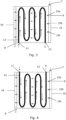
- FIG. 4 illustrates an alternative embodiment of the cooling arrangement 1.
- FIG. 4 schematically illustrates the flow of the first coolant 9 and the second coolant 13 within the cooling arrangement 1, the flows of the first coolant 9 and the second coolant 13 being illustrated with arrows.
- the first coolant 9 is supplied to the battery cells via the openings 15a-c of the coolant conduit 15 and is allowed to successively immerse the battery cells 3 until it reaches the first outlet conduit 16.
- the second coolant 9 is supplied to the cooling plate 10 through the coolant channel inlet 11 and transported through the coolant channel 14 in thermal contact with the battery cells 3, until it is disposed through the coolant channel outlet 12.
- FIG. 4 schematically illustrates the flow of the first coolant 9 and the second coolant 13 within the cooling arrangement 1, the flows of the first coolant 9 and the second coolant 13 being illustrated with arrows.
- the first coolant 9 is supplied to the battery cells via the openings 15a-c of the coolant conduit 15 and is allowed to successively immerse the battery cells 3 until it reaches
- the coolant conduit 15 is arranged at an opposite side of the enclosure 4 with respect to the coolant channel inlet 11 in one horizontal direction, specifically in the left-right direction of FIG. 4 .
- the inlet point 7 of the first coolant 9 is in FIG. 4 arranged at the same side as the inlet point 7 of the second coolant 9 with regards to the top-bottom direction of FIG. 4 .
- This embodiment might facilitate assembly of the cooling arrangement within a vehicle, as the coolant inlet points are accessible from the same side, it could also allow for the first coolant 9 and the second coolant 13 to be supplied from the same coolant supply.
- FIG. 5 is an exemplary cooling arrangement 1 in accordance with an alternative embodiment of the present disclosure.
- the cooling arrangement 1 is illustrated in relation to an electrical storage system 2.
- the electrical storage system 2 comprises a plurality of battery cells 3 for storing of energy in chemical bonds.
- the battery cells 3 have a cylindrical form and are closely stacked together to form the electrical storage system 2.
- the disclosure is not limited to any specific form or number of battery cells 3.
- the battery cells 3 are in FIG. 1 accommodated within an enclosure 4.
- the enclosure 4 keeps the battery cells 3 together and protects the battery cells 3.
- the enclosure 4 could according to one example comprise polycarbonate.
- the cooling arrangement exemplified in FIG. 5 further comprises a coolant inlet point 7 and a coolant outlet point 8.
- the coolant inlet point 7 is connected to an inlet conduit 15 extending along a top side of the enclosure 4 for depositing a first coolant 9 into direct contact with the battery cells 3.
- the coolant inlet point 7 is in turn connected to a first coolant supply (not shown).
- the first coolant 9 As the first coolant 9 is supplied to the electrical storage system 2, it successively immerses the battery cells 3 with the first coolant 9. As the first coolant 9 reaches the coolant outlet point 8 at a top section of the electrical storage system 2, the coolant is expelled from the cooling arrangement 1.
- An outlet conduit 16 is connected to the coolant outlet point 8. As the first coolant 9 reaches a certain level it flows into the outlet conduit 16 whereby it can be transported away from the cooling arrangement 1 through the coolant outlet point 8.
- FIG. 5 further illustrates a cooling plate 10 arranged at a lower section of the enclosure 4.
- the cooling plate 10 comprises a coolant channel inlet 11 and a coolant channel outlet 12.
- the inlet 11 and the coolant channel outlet 12 of the are in FIG. 5 illustrated as being arranged on a same side of the cooling plate 10 but might as well be arranged at different sides.
- the coolant channel inlet 11 and the coolant channel outlet 12 are connected to external conduits (not shown) for feeding a second coolant 13 into the cooling arrangement 1 and for leading the second coolant 13 away from the cooling arrangement 1.
- the cooling plate 10 could be installed in other ways in relation to the battery cells 3 of the electrical storage system 2, such as at an upper side of the electrical storage system 2, on top of the battery cells 3.
- Relative terms such as “below” or “above” or “upper” or “lower” or “horizontal” or “vertical” may be used herein to describe a relationship of one element to another element as illustrated in the Figures. It will be understood that these terms and those discussed above are intended to encompass different orientations of the device in addition to the orientation depicted in the Figures. It will be understood that when an element is referred to as being “connected” or “coupled” to another element, it can be directly connected or coupled to the other element, or intervening elements may be present. In contrast, when an element is referred to as being “directly connected” or “directly coupled” to another element, there are no intervening elements present.
Landscapes
- Chemical & Material Sciences (AREA)
- Chemical Kinetics & Catalysis (AREA)
- Electrochemistry (AREA)
- General Chemical & Material Sciences (AREA)
- Engineering & Computer Science (AREA)
- Manufacturing & Machinery (AREA)
- Secondary Cells (AREA)
- Battery Mounting, Suspending (AREA)
Abstract
Description
- The disclosure relates generally to a cooling arrangement. In particular aspects, the disclosure relates to a cooling arrangement for an electrical storage system. The disclosure can be applied in heavy-duty vehicles, such as trucks, buses, and construction equipment. Although the disclosure may be described with respect to a particular vehicle, the disclosure is not restricted to any particular vehicle. The disclosure could further be applied to stationary electrical storage systems, or to electrical storage systems in aviation or marine applications.
- An electrical storage system stores energy for subsequent use. One example of an electrical storage system is a battery, such as a rechargeable battery for an electric vehicle.
- Electrical storage systems may comprise battery cells for storing of energy in chemical bonds. During charging and recharging of the electrical storage system, the battery cells produce heat. To avoid damage and improve performance of the electrical storage system, a cooling arrangement may be used to cool the battery cells.
- One previously known cooling method is immersion cooling. During immersion cooling the battery cells are immersed in a cooling liquid for cooling the cells through direct contact.
- Another known method is cold-plate cooling. During cold-plate cooling, the battery cells are put into contact with a plate, the plate comprising a coolant channel for transporting the coolant into thermal contact with the battery cells.
- Both of these previously known solutions come with limitations. While immersion cooling provides greater thermal contact with all sides of the battery cells, and thereby achieves a more homogenous cooling within each battery cell, the method may demand a large amount of pump power to provide a sufficiently high flow rate for achieving proper cooling of all battery cells and to reduce spatial thermal variation between different cells in the system.
- The cooling plate transports the coolant in a channel physically separated from the battery cells and may require less pump power to achieve homogenous cooling among the battery cells but may instead result in inhomogeneous temperature distribution within the battery cells as they are typically cooled from one direction only.
- The present disclosure relates to a cooling arrangement for an electrical storage system which may remediate some of these problems.
- According to a first aspect of the disclosure, a cooling arrangement for an electrical storage system is provided, the cooling arrangement comprising an inlet conduit via which a first coolant is supplied to the cooling arrangement and deposited via one or more openings of the inlet conduit into a cooling arrangement enclosure for setting the first coolant into direct contact with at least one battery cell accommodated within the enclosure, the inlet conduit extending along a side of the enclosure. The cooling arrangement further comprising a coolant channel carrying a second coolant, the coolant channel being configured to be in thermal contact with the at least one battery cell. A coolant channel inlet of the coolant channel being arranged at an opposite side of the enclosure in relation to the inlet conduit and the flow direction of the second coolant at the coolant channel inlet being configured to be orthogonal to a flow direction of the first coolant exiting said one or more openings.
- The first aspect of the disclosure may seek to solve the problem of reducing cooling arrangement pump power while still achieving homogeneous cooling of the battery cells.
- By providing the cooling arrangement with two separate coolants and by arranging the inlets of these coolants opposite to each other with respect to the enclosure and the battery cells enclosed therein, the two separate coolants will cooperate to provide a more homogenous cooling of the at least one battery cell, as the arrangement allows the two separate coolants to move in opposite and orthogonal directions, thus compensating for the successively decreased cooling effect of the coolants due to heat exchange with the battery cells.
- Furthermore, the combination of indirect cooling and direct cooling could further improve the cooling capabilities. As the indirect cooling may cool the at least one battery cell from a specific direction, such as from below, while the direct cooling partly or entirely immerses the at least one battery cell in coolant, different cooling properties are archived.
- When the coolant is allowed to come into direct contact with the at least one battery cell, a more homogenous cooling within the battery cell may be achieved, as the battery cell may be cooled from several directions. The indirect cooling allows the one or more battery cells to be cooled using a lower flow rate, as the coolant of the indirect cooling is not physically hindered by the battery cells.
- A technical benefit may thus include a cooling arrangement with more homogenous cooling and with lowered pumping demands.
- In some examples, the first coolant is supplied to the inlet conduit at an inlet point, the inlet point being arranged diagonally from the coolant channel inlet of the coolant channel, with respect to a bottom section of the enclosure. A technical benefit might be that a more homogenous cooling of the at least one battery cell may be achieved.
- In some examples, the first coolant is disposed from the cooling arrangement at a coolant outlet point and the second coolant is disposed from the cooling arrangement at a channel coolant outlet.
- In some examples, the cooling arrangement is configured to immerse the entire at least one battery cell with the first coolant. A technical benefit may include a more homogenous cooling within the battery cells.
- In some examples, the inlet conduit is arranged at a bottom section of the enclosure.
- In some examples, the coolant outlet point is connected to an outlet conduit, the outlet conduit extending substantially horizontally along a side of the enclosure. A technical benefit may include that the first coolant is more evenly distributed into the disclosure. A technical benefit may include an efficient dispose of the coolant from the cooling arrangement.
- In some examples, the outlet conduit is arranged at a top section of the enclosure.
- In some examples, the coolant channel comprises a copper tube. A technical benefit may include a good thermal exchange between the coolant channel and the battery cells of the electrical storage system.
- In some examples, the coolant channel is arranged inside a cooling plate. A technical benefit may include that a more even thermal distribution of coolant could be achieved.
- In some examples the cooling plate is configured to form a bottom of the enclosure. A technical benefit may include a cooling arrangement with less components and better heat exchange.
- In some examples the at least one battery cell is affixed to the top of the cooling plate.
- In some examples the first coolant is a dielectric fluid. A technical benefit may include that good insulating properties can be achieved.
- In some examples, the enclosure comprises polycarbonate.
- According to a second aspect of the disclosure, an electrical storage system comprising the proposed cooling arrangement is provided.
- According to a third aspect of the disclosure, a vehicle comprising the proposed electrical storage including the proposed cooling arrangement is provided.
- The above aspects, accompanying claims, and/or examples disclosed herein above and later below may be suitably combined with each other as would be apparent to anyone of ordinary skill in the art.
- Additional features and advantages are disclosed in the following description, claims, and drawings, and in part will be readily apparent therefrom to those skilled in the art or recognized by practicing the disclosure as described herein. There are also disclosed herein control units, computer readable media, and computer program products associated with the above discussed technical benefits.
- With reference to the appended drawings, below follows a more detailed description of aspects of the disclosure cited as examples.
-
FIG. 1 is a perspective view of an exemplary cooling arrangement -
FIG. 2 is a top view an exemplary cooling arrangement along section S1 infig. 1 -
FIG. 3 is a schematic top view of an exemplary cooling arrangement showing the coolant flows within the arrangement -
FIG. 4 is an alternative embodiment of a cooling arrangement of the present disclosure -
FIG. 5 is a further alternative embodiment of a cooling arrangement of the present disclosure - Aspects set forth below represent the necessary information to enable those skilled in the art to practice the disclosure.
-
FIG. 1 is anexemplary cooling arrangement 1 in accordance with the present disclosure. Thecooling arrangement 1 is illustrated in relation to anelectrical storage system 2. Theelectrical storage system 2 comprises a plurality ofbattery cells 3 for storing of energy in chemical bonds. Thebattery cells 3 have a cylindrical form and are closely stacked together to form theelectrical storage system 2. The disclosure is not limited to any specific form or number ofbattery cells 3. Thebattery cells 3 are inFIG. 1 accommodated within anenclosure 4. Theenclosure 4 keeps thebattery cells 3 together and protects thebattery cells 3. Theenclosure 4 could according to one example comprise polycarbonate. - The cooling arrangement exemplified in
FIG. 1 further comprises acoolant inlet point 7 and acoolant outlet point 8. Thecoolant inlet point 7 is connected to aninlet conduit 15 extending along a bottom side of theenclosure 4. Theinlet conduit 15 comprises at least one opening, inFIG.1 illustrated as threeopenings 15a-c, for depositing afirst coolant 9 into direct contact with thebattery cells 3. Thecoolant inlet point 7 is in turn connected to a first coolant supply (not shown). The coolant outlet point is connected to anoutlet conduit 16. - As the
first coolant 9 is supplied at a bottom section of theelectrical storage system 2, it rises within theenclosure 4 and thereby successively immerses thebattery cells 3 with thefirst coolant 9. As thefirst coolant 9 reaches a certain level it flows into theoutlet conduit 16 at the top section of theenclosure 4 from where it can be transported away from thecooling arrangement 1 via thecoolant outlet point 8. Thefirst coolant 9 could immerse thebattery cells 3 partly or entirely depending on the placement of theoutlet conduit 16. -
FIG. 1 further illustrates acooling plate 10 arranged at a lower section of theenclosure 4. The coolingplate 10 comprises acoolant channel inlet 11 and acoolant channel outlet 12. Thecoolant channel inlet 11 and thecoolant channel outlet 12 are inFIG. 1 illustrated as being arranged on a same side of the coolingplate 10 but might as well be arranged at opposite sides of the coolingplate 10. Thecoolant channel inlet 11 and thecoolant channel outlet 12 are connected to external conduits (not shown) for feeding asecond coolant 13 into thecooling arrangement 1 and for leading thesecond coolant 13 away from thecooling arrangement 1. - The cooling
plate 10 could be installed in other ways in relation to thebattery cells 3 of theelectrical storage system 2, such as at an upper side of theelectrical storage system 2, on top of thebattery cells 3. -
FIG. 2 shows an exemplary cooling arrangement along section S1. InFIG. 2 , the inside of the coolingplate 10 is clearly shown. The coolingplate 10 shown inFIG. 2 comprises aninterior channel 14 for transporting thesecond coolant 13. Thecoolant channel 14 inFIG. 2 comprises a copper pipe which extends across the coolingplate 10 to achieve thermal exchange with thebattery cells 3 within thebattery storage system 2. Other configurations, patterns or materials of thecoolant channel 14 may be envisaged. For example, the coolingplate 10 could comprise a number ofparallel coolant channels 14 extending from thecoolant channel inlet 11 and converging towards thecoolant channel outlet 12. -
FIG. 3 is anexemplary cooling arrangement 1 illustrated in a schematic top view. The figure schematically illustrates the flow of thefirst coolant 9 and thesecond coolant 13 within thecooling arrangement 1, the flows of thefirst coolant 9 and thesecond coolant 13 being illustrated with arrows. Thefirst coolant 9 is deposited to the battery cells via theopenings 15a-c of thecoolant conduit 15 and is allowed to successively immerse thebattery cells 3 until it reaches thefirst outlet conduit 16. Thesecond coolant 9 is supplied to thecooling plate 10 via thecoolant channel inlet 11 and transported through thecoolant channel 14 in thermal contact with thebattery cells 3, until it is disposed at thecoolant channel outlet 12. InFIG. 3 , thecoolant conduit 15 is arranged at an opposite side of the electrical storage system with respect to thecoolant channel inlet 11. Furthermore, thecoolant inlet point 7 is inFIG. 3 arranged at the opposite side of thecoolant channel inlet 11 in two directions with regards to the bottom of theenclosure 4, in other words diagonally. Thecoolant inlet point 7 could in other embodiments be arranged opposite to thecoolant channel inlet 11 in only one direction with respect to the bottom of theenclosure 4. - As is illustrated by the plurality of arrows in
FIG. 3 , this arrangement allows the twoseparate coolants first coolant 9 approaches theoutlet conduit 16 its reduced cooling effect is thus compensated by the cooling effect ofsecond coolant 13 supplied at thecoolant channel inlet 11. -
FIG. 4 illustrates an alternative embodiment of thecooling arrangement 1.FIG. 4 schematically illustrates the flow of thefirst coolant 9 and thesecond coolant 13 within thecooling arrangement 1, the flows of thefirst coolant 9 and thesecond coolant 13 being illustrated with arrows. Thefirst coolant 9 is supplied to the battery cells via theopenings 15a-c of thecoolant conduit 15 and is allowed to successively immerse thebattery cells 3 until it reaches thefirst outlet conduit 16. Thesecond coolant 9 is supplied to thecooling plate 10 through thecoolant channel inlet 11 and transported through thecoolant channel 14 in thermal contact with thebattery cells 3, until it is disposed through thecoolant channel outlet 12. InFIG. 4 , thecoolant conduit 15 is arranged at an opposite side of theenclosure 4 with respect to thecoolant channel inlet 11 in one horizontal direction, specifically in the left-right direction ofFIG. 4 . Theinlet point 7 of thefirst coolant 9 is inFIG. 4 arranged at the same side as theinlet point 7 of thesecond coolant 9 with regards to the top-bottom direction ofFIG. 4 . This embodiment might facilitate assembly of the cooling arrangement within a vehicle, as the coolant inlet points are accessible from the same side, it could also allow for thefirst coolant 9 and thesecond coolant 13 to be supplied from the same coolant supply. -
FIG. 5 is anexemplary cooling arrangement 1 in accordance with an alternative embodiment of the present disclosure. Thecooling arrangement 1 is illustrated in relation to anelectrical storage system 2. Theelectrical storage system 2 comprises a plurality ofbattery cells 3 for storing of energy in chemical bonds. Thebattery cells 3 have a cylindrical form and are closely stacked together to form theelectrical storage system 2. The disclosure is not limited to any specific form or number ofbattery cells 3. Thebattery cells 3 are inFIG. 1 accommodated within anenclosure 4. Theenclosure 4 keeps thebattery cells 3 together and protects thebattery cells 3. Theenclosure 4 could according to one example comprise polycarbonate. - The cooling arrangement exemplified in
FIG. 5 further comprises acoolant inlet point 7 and acoolant outlet point 8. Thecoolant inlet point 7 is connected to aninlet conduit 15 extending along a top side of theenclosure 4 for depositing afirst coolant 9 into direct contact with thebattery cells 3. Thecoolant inlet point 7 is in turn connected to a first coolant supply (not shown). - As the
first coolant 9 is supplied to theelectrical storage system 2, it successively immerses thebattery cells 3 with thefirst coolant 9. As thefirst coolant 9 reaches thecoolant outlet point 8 at a top section of theelectrical storage system 2, the coolant is expelled from thecooling arrangement 1. - An
outlet conduit 16 is connected to thecoolant outlet point 8. As thefirst coolant 9 reaches a certain level it flows into theoutlet conduit 16 whereby it can be transported away from thecooling arrangement 1 through thecoolant outlet point 8. -
FIG. 5 further illustrates acooling plate 10 arranged at a lower section of theenclosure 4. The coolingplate 10 comprises acoolant channel inlet 11 and acoolant channel outlet 12. Theinlet 11 and thecoolant channel outlet 12 of the are inFIG. 5 illustrated as being arranged on a same side of the coolingplate 10 but might as well be arranged at different sides. Thecoolant channel inlet 11 and thecoolant channel outlet 12 are connected to external conduits (not shown) for feeding asecond coolant 13 into thecooling arrangement 1 and for leading thesecond coolant 13 away from thecooling arrangement 1. - The cooling
plate 10 could be installed in other ways in relation to thebattery cells 3 of theelectrical storage system 2, such as at an upper side of theelectrical storage system 2, on top of thebattery cells 3. - The terminology used herein is for the purpose of describing particular aspects only and is not intended to be limiting of the disclosure. As used herein, the singular forms "a," "an," and "the" are intended to include the plural forms as well, unless the context clearly indicates otherwise. As used herein, the term "and/or" includes any and all combinations of one or more of the associated listed items. It will be further understood that the terms "comprises," "comprising," "includes," and/or "including" when used herein specify the presence of stated features, integers, steps, operations, elements, and/or components, but do not preclude the presence or addition of one or more other features, integers, steps, operations, elements, components, and/or groups thereof.
- It will be understood that, although the terms first, second, etc., may be used herein to describe various elements, these elements should not be limited by these terms. These terms are only used to distinguish one element from another. For example, a first element could be termed a second element, and, similarly, a second element could be termed a first element without departing from the scope of the present disclosure.
- Relative terms such as "below" or "above" or "upper" or "lower" or "horizontal" or "vertical" may be used herein to describe a relationship of one element to another element as illustrated in the Figures. It will be understood that these terms and those discussed above are intended to encompass different orientations of the device in addition to the orientation depicted in the Figures. It will be understood that when an element is referred to as being "connected" or "coupled" to another element, it can be directly connected or coupled to the other element, or intervening elements may be present. In contrast, when an element is referred to as being "directly connected" or "directly coupled" to another element, there are no intervening elements present.
- Unless otherwise defined, all terms (including technical and scientific terms) used herein have the same meaning as commonly understood by one of ordinary skill in the art to which this disclosure belongs. It will be further understood that terms used herein should be interpreted as having a meaning consistent with their meaning in the context of this specification and the relevant art and will not be interpreted in an idealized or overly formal sense unless expressly so defined herein.
- It is to be understood that the present disclosure is not limited to the aspects described above and illustrated in the drawings; rather, the skilled person will recognize that many changes and modifications may be made within the scope of the present disclosure and appended claims. In the drawings and specification, there have been disclosed aspects for purposes of illustration only and not for purposes of limitation, the scope of the inventive concepts being set forth in the following claims.
Claims (15)
- A cooling arrangement (1) for an electrical storage system (2), the cooling arrangement (1) comprising:an inlet conduit (15) via which a first coolant (9) is supplied to the cooling arrangement (1) and deposited via one or more openings (15a-c) of the inlet conduit (15) into a cooling arrangement enclosure (4) for setting the first coolant (9) into direct contact with at least one battery cell (3) accommodated within the enclosure (4), the inlet conduit (15) extending along a side of the enclosure (4);a coolant channel (14) carrying a second coolant (13), the coolant channel (14) being configured to be in thermal contact with the at least one battery cell (3), a coolant channel inlet (11) of the coolant channel (14) being arranged at an opposite side of the enclosure (4) in relation to the inlet conduit (15), whereinthe flow direction of the second coolant (13) at the coolant channel inlet (11) is configured to be orthogonal to a flow direction of the first coolant (9) exiting said one or more openings (15a-c).
- The cooling arrangement (1) of claim 1 wherein the first coolant (9) is supplied to the inlet conduit (15) at an inlet point (7) being arranged diagonally from the coolant channel inlet (11), with respect to a bottom section of the enclosure (4).
- The cooling arrangement (1) of claim 1 wherein the first coolant (9) is disposed from the cooling arrangement at a coolant outlet point (8) and the second coolant is disposed from the cooling arrangement at a coolant channel outlet (12).
- The cooling arrangement (1) of claim 1 wherein the cooling arrangement (1) is configured to immerse the entire at least one battery cell (3) with the first coolant (9).
- The cooling arrangement (1) of claim 1 wherein the inlet conduit (15) is arranged at a bottom section of the enclosure (4).
- The cooling arrangement (1) of claim 3 wherein the coolant outlet point (8) is connected to an outlet conduit (16), the outlet conduit (16) extending substantially horizontally along a side of the enclosure (4).
- The cooling arrangement (1) of claim 6 wherein outlet conduit (16) is arranged at a top section of the enclosure (4).
- The cooling arrangement (1) of claim 1 wherein the cooling channel (14) comprises a copper tube.
- The cooling arrangement (1) of claim 1 wherein the coolant channel (14) is arranged inside a cooling plate (10).
- The cooling arrangement (1) of claim 9 wherein the cooling plate (10) is configured to form a bottom of the enclosure (4).
- The cooling arrangement (1) of claim 9 wherein the at least one battery cell (3) is affixed to an upper side of the cooling plate (10).
- The cooling arrangement (1) of claim 1 wherein the first coolant (9) is a dielectric fluid.
- The cooling arrangement (1) of claim 1 wherein the enclosure (4) comprises polycarbonate.
- An electrical storage system comprising the cooling arrangement of any of claims 1-13.
- A vehicle comprising the electrical storage system of claim 14.
Priority Applications (2)
| Application Number | Priority Date | Filing Date | Title |
|---|---|---|---|
| EP22202142.0A EP4358235A1 (en) | 2022-10-18 | 2022-10-18 | Cooling arrangement for an electrical storage system |
| US18/484,725 US20240128546A1 (en) | 2022-10-18 | 2023-10-11 | Cooling arrangement for an electrical storage system |
Applications Claiming Priority (1)
| Application Number | Priority Date | Filing Date | Title |
|---|---|---|---|
| EP22202142.0A EP4358235A1 (en) | 2022-10-18 | 2022-10-18 | Cooling arrangement for an electrical storage system |
Publications (1)
| Publication Number | Publication Date |
|---|---|
| EP4358235A1 true EP4358235A1 (en) | 2024-04-24 |
Family
ID=83902966
Family Applications (1)
| Application Number | Title | Priority Date | Filing Date |
|---|---|---|---|
| EP22202142.0A Pending EP4358235A1 (en) | 2022-10-18 | 2022-10-18 | Cooling arrangement for an electrical storage system |
Country Status (2)
| Country | Link |
|---|---|
| US (1) | US20240128546A1 (en) |
| EP (1) | EP4358235A1 (en) |
Cited By (1)
| Publication number | Priority date | Publication date | Assignee | Title |
|---|---|---|---|---|
| EP4734227A1 (en) * | 2024-09-27 | 2026-04-29 | Eve Energy Storage Co., Ltd | Battery packs and battery systems |
Families Citing this family (2)
| Publication number | Priority date | Publication date | Assignee | Title |
|---|---|---|---|---|
| WO2025237524A1 (en) * | 2024-05-16 | 2025-11-20 | Whitemark Technology GmbH | Battery module with heat exchanger housing for immersion cooling |
| CN118398975B (en) * | 2024-06-28 | 2024-10-01 | 天通优能科技有限公司 | A cold plate with prismatic epitaxial fins and a battery thermal management system |
Citations (7)
| Publication number | Priority date | Publication date | Assignee | Title |
|---|---|---|---|---|
| JP2013004468A (en) * | 2011-06-21 | 2013-01-07 | Sharp Corp | Battery pack device |
| EP2950379A1 (en) * | 2014-05-30 | 2015-12-02 | Siemens Aktiengesellschaft | Electrical energy storage device |
| US20200266507A1 (en) * | 2019-02-18 | 2020-08-20 | 3M Innovative Properties Company | Battery module and system |
| US20210391611A1 (en) * | 2020-06-11 | 2021-12-16 | Global Graphene Group, Inc. | Battery module or pack with a distributed cooling and fire protection system and method of operating same |
| DE102020124745A1 (en) * | 2020-09-23 | 2022-03-24 | Lisa Dräxlmaier GmbH | BATTERY MODULE HOUSING AND METHOD OF MAKING A BATTERY MODULE |
| EP4037066A1 (en) * | 2021-02-02 | 2022-08-03 | Aurora Flight Sciences Corporation, a subsidiary of The Boeing Company | Methods and apparatus for thermal management of batteries |
| WO2022237986A1 (en) * | 2021-05-14 | 2022-11-17 | Whitemark Technology GmbH | Battery module and battery system with heat exchanger housing |
-
2022
- 2022-10-18 EP EP22202142.0A patent/EP4358235A1/en active Pending
-
2023
- 2023-10-11 US US18/484,725 patent/US20240128546A1/en active Pending
Patent Citations (7)
| Publication number | Priority date | Publication date | Assignee | Title |
|---|---|---|---|---|
| JP2013004468A (en) * | 2011-06-21 | 2013-01-07 | Sharp Corp | Battery pack device |
| EP2950379A1 (en) * | 2014-05-30 | 2015-12-02 | Siemens Aktiengesellschaft | Electrical energy storage device |
| US20200266507A1 (en) * | 2019-02-18 | 2020-08-20 | 3M Innovative Properties Company | Battery module and system |
| US20210391611A1 (en) * | 2020-06-11 | 2021-12-16 | Global Graphene Group, Inc. | Battery module or pack with a distributed cooling and fire protection system and method of operating same |
| DE102020124745A1 (en) * | 2020-09-23 | 2022-03-24 | Lisa Dräxlmaier GmbH | BATTERY MODULE HOUSING AND METHOD OF MAKING A BATTERY MODULE |
| EP4037066A1 (en) * | 2021-02-02 | 2022-08-03 | Aurora Flight Sciences Corporation, a subsidiary of The Boeing Company | Methods and apparatus for thermal management of batteries |
| WO2022237986A1 (en) * | 2021-05-14 | 2022-11-17 | Whitemark Technology GmbH | Battery module and battery system with heat exchanger housing |
Cited By (1)
| Publication number | Priority date | Publication date | Assignee | Title |
|---|---|---|---|---|
| EP4734227A1 (en) * | 2024-09-27 | 2026-04-29 | Eve Energy Storage Co., Ltd | Battery packs and battery systems |
Also Published As
| Publication number | Publication date |
|---|---|
| US20240128546A1 (en) | 2024-04-18 |
Similar Documents
| Publication | Publication Date | Title |
|---|---|---|
| US20240128546A1 (en) | Cooling arrangement for an electrical storage system | |
| US11217836B2 (en) | Cooling jacket having nonuniform flow paths, for cooling battery cell surface, and battery module including same | |
| US20240234871A1 (en) | Thermal management of a liquid cooled module | |
| CN103959508B (en) | There is the battery system of the temperature control body comprising homoiothermic passage and bypass and comprise the motor vehicles of battery system | |
| CN110600788B (en) | Soft packet of power battery package of electric automobile based on utmost point ear heat dissipation and thermal management system thereof | |
| CN108923097B (en) | Magnetic fluid liquid cooling plate, liquid cooling system composed of magnetic fluid liquid cooling plate and control method | |
| CN102916234A (en) | Battery pack liquid cooling system | |
| EP3644432A1 (en) | Immersion cooling device for power battery | |
| US20230231224A1 (en) | Battery and electric device | |
| CN115117514B (en) | A staggered counter-flow integrated cooling system and electric vehicle | |
| CN217507463U (en) | Battery rack and battery cluster unit | |
| EP4360945B1 (en) | Vehicular energy storage module, battery pack and vehicle | |
| CN116345017A (en) | Power battery system and new energy vehicles | |
| CN112490569A (en) | Micro-channel type battery liquid cooling structure | |
| CN110323516A (en) | Battery pack heat-exchange system | |
| CN218333982U (en) | Battery pack box structure, battery pack and electric device | |
| CN217589135U (en) | Power battery module and battery temperature control system | |
| CN118888918B (en) | Immersed energy storage system and cooling regulation method | |
| CN116979182B (en) | Liquid cooling battery box and energy storage container | |
| WO2024250694A1 (en) | Battery and electrical device | |
| EP4239767A1 (en) | A battery system | |
| US20260038906A1 (en) | Systems and methods for battery temperature management | |
| CN115377537A (en) | Battery pack integrated wireless charging module system, structure and method | |
| CN115663331A (en) | Battery pack box structure, battery pack and electrical device | |
| US20260038942A1 (en) | Modular energy storage system with temperature control |
Legal Events
| Date | Code | Title | Description |
|---|---|---|---|
| PUAI | Public reference made under article 153(3) epc to a published international application that has entered the european phase |
Free format text: ORIGINAL CODE: 0009012 |
|
| STAA | Information on the status of an ep patent application or granted ep patent |
Free format text: STATUS: THE APPLICATION HAS BEEN PUBLISHED |
|
| AK | Designated contracting states |
Kind code of ref document: A1 Designated state(s): AL AT BE BG CH CY CZ DE DK EE ES FI FR GB GR HR HU IE IS IT LI LT LU LV MC ME MK MT NL NO PL PT RO RS SE SI SK SM TR |
|
| STAA | Information on the status of an ep patent application or granted ep patent |
Free format text: STATUS: REQUEST FOR EXAMINATION WAS MADE |
|
| 17P | Request for examination filed |
Effective date: 20241018 |
|
| RBV | Designated contracting states (corrected) |
Designated state(s): AL AT BE BG CH CY CZ DE DK EE ES FI FR GB GR HR HU IE IS IT LI LT LU LV MC ME MK MT NL NO PL PT RO RS SE SI SK SM TR |