EP4358169A2 - Secondary battery and manufacturing method for the same - Google Patents
Secondary battery and manufacturing method for the same Download PDFInfo
- Publication number
- EP4358169A2 EP4358169A2 EP23202875.3A EP23202875A EP4358169A2 EP 4358169 A2 EP4358169 A2 EP 4358169A2 EP 23202875 A EP23202875 A EP 23202875A EP 4358169 A2 EP4358169 A2 EP 4358169A2
- Authority
- EP
- European Patent Office
- Prior art keywords
- compound
- negative electrode
- substance
- solid electrolyte
- current collector
- Prior art date
- Legal status (The legal status is an assumption and is not a legal conclusion. Google has not performed a legal analysis and makes no representation as to the accuracy of the status listed.)
- Pending
Links
- 238000004519 manufacturing process Methods 0.000 title claims description 20
- 229910052751 metal Inorganic materials 0.000 claims abstract description 198
- 239000002184 metal Substances 0.000 claims abstract description 197
- 239000000126 substance Substances 0.000 claims abstract description 158
- 239000007784 solid electrolyte Substances 0.000 claims abstract description 156
- 150000001875 compounds Chemical class 0.000 claims abstract description 131
- 229910052744 lithium Inorganic materials 0.000 claims abstract description 92
- 230000015572 biosynthetic process Effects 0.000 claims abstract description 87
- WHXSMMKQMYFTQS-UHFFFAOYSA-N Lithium Chemical compound [Li] WHXSMMKQMYFTQS-UHFFFAOYSA-N 0.000 claims abstract description 82
- 239000007774 positive electrode material Substances 0.000 claims abstract description 70
- 239000007773 negative electrode material Substances 0.000 claims abstract description 60
- 229910045601 alloy Inorganic materials 0.000 claims abstract description 42
- 239000000956 alloy Substances 0.000 claims abstract description 42
- 238000000034 method Methods 0.000 claims description 25
- 229910052796 boron Inorganic materials 0.000 claims description 23
- 229910052698 phosphorus Inorganic materials 0.000 claims description 23
- 229910001416 lithium ion Inorganic materials 0.000 claims description 21
- 229910052739 hydrogen Inorganic materials 0.000 claims description 19
- 229910052738 indium Inorganic materials 0.000 claims description 12
- 229910052725 zinc Inorganic materials 0.000 claims description 12
- 229910052785 arsenic Inorganic materials 0.000 claims description 10
- 229910052710 silicon Inorganic materials 0.000 claims description 10
- 229910052718 tin Inorganic materials 0.000 claims description 10
- 229910052787 antimony Inorganic materials 0.000 claims description 9
- 229910052740 iodine Inorganic materials 0.000 claims description 8
- HBBGRARXTFLTSG-UHFFFAOYSA-N Lithium ion Chemical compound [Li+] HBBGRARXTFLTSG-UHFFFAOYSA-N 0.000 claims description 7
- 229910052711 selenium Inorganic materials 0.000 claims description 7
- 229910052797 bismuth Inorganic materials 0.000 claims description 6
- 229910052793 cadmium Inorganic materials 0.000 claims description 6
- 229910052753 mercury Inorganic materials 0.000 claims description 6
- 239000010410 layer Substances 0.000 description 259
- 239000011777 magnesium Substances 0.000 description 88
- PNUZDKCDAWUEGK-CYZMBNFOSA-N Sitafloxacin Chemical compound C([C@H]1N)N(C=2C(=C3C(C(C(C(O)=O)=CN3[C@H]3[C@H](C3)F)=O)=CC=2F)Cl)CC11CC1 PNUZDKCDAWUEGK-CYZMBNFOSA-N 0.000 description 54
- 229940126639 Compound 33 Drugs 0.000 description 50
- 239000002245 particle Substances 0.000 description 41
- 238000011156 evaluation Methods 0.000 description 37
- 238000000151 deposition Methods 0.000 description 33
- 230000008021 deposition Effects 0.000 description 32
- 239000002203 sulfidic glass Substances 0.000 description 29
- 230000000052 comparative effect Effects 0.000 description 28
- 238000007599 discharging Methods 0.000 description 27
- 239000011888 foil Substances 0.000 description 26
- PXHVJJICTQNCMI-UHFFFAOYSA-N nickel Substances [Ni] PXHVJJICTQNCMI-UHFFFAOYSA-N 0.000 description 26
- 229910052749 magnesium Inorganic materials 0.000 description 22
- 239000011230 binding agent Substances 0.000 description 18
- 239000011241 protective layer Substances 0.000 description 17
- 238000006243 chemical reaction Methods 0.000 description 16
- 229910012375 magnesium hydride Inorganic materials 0.000 description 16
- 239000010408 film Substances 0.000 description 15
- 230000000452 restraining effect Effects 0.000 description 12
- 229910052782 aluminium Inorganic materials 0.000 description 11
- 230000000694 effects Effects 0.000 description 11
- 229910052759 nickel Inorganic materials 0.000 description 11
- 229910000733 Li alloy Inorganic materials 0.000 description 10
- 239000001989 lithium alloy Substances 0.000 description 10
- 238000004806 packaging method and process Methods 0.000 description 9
- 238000009826 distribution Methods 0.000 description 7
- 229910003480 inorganic solid Inorganic materials 0.000 description 7
- 239000007787 solid Substances 0.000 description 7
- 239000000758 substrate Substances 0.000 description 7
- OKTJSMMVPCPJKN-UHFFFAOYSA-N Carbon Chemical compound [C] OKTJSMMVPCPJKN-UHFFFAOYSA-N 0.000 description 6
- 229910000861 Mg alloy Inorganic materials 0.000 description 6
- 229910020073 MgB2 Inorganic materials 0.000 description 6
- -1 conductive aid Substances 0.000 description 6
- 239000005001 laminate film Substances 0.000 description 6
- 229910001635 magnesium fluoride Inorganic materials 0.000 description 6
- 239000000463 material Substances 0.000 description 6
- 238000005259 measurement Methods 0.000 description 6
- 239000000203 mixture Substances 0.000 description 6
- 230000006911 nucleation Effects 0.000 description 6
- 238000010899 nucleation Methods 0.000 description 6
- 229920005989 resin Polymers 0.000 description 6
- 239000011347 resin Substances 0.000 description 6
- 229910001220 stainless steel Inorganic materials 0.000 description 6
- 239000010935 stainless steel Substances 0.000 description 6
- 239000010409 thin film Substances 0.000 description 6
- 230000008859 change Effects 0.000 description 5
- 239000002131 composite material Substances 0.000 description 5
- 239000013078 crystal Substances 0.000 description 5
- 239000008151 electrolyte solution Substances 0.000 description 5
- 229910052733 gallium Inorganic materials 0.000 description 5
- 229910052732 germanium Inorganic materials 0.000 description 5
- 238000010030 laminating Methods 0.000 description 5
- AMXOYNBUYSYVKV-UHFFFAOYSA-M lithium bromide Inorganic materials [Li+].[Br-] AMXOYNBUYSYVKV-UHFFFAOYSA-M 0.000 description 5
- 239000002134 carbon nanofiber Substances 0.000 description 4
- 229910052804 chromium Inorganic materials 0.000 description 4
- 230000006835 compression Effects 0.000 description 4
- 238000007906 compression Methods 0.000 description 4
- 239000000470 constituent Substances 0.000 description 4
- 230000003247 decreasing effect Effects 0.000 description 4
- 238000004090 dissolution Methods 0.000 description 4
- 239000003792 electrolyte Substances 0.000 description 4
- 239000011521 glass Substances 0.000 description 4
- 229910052742 iron Inorganic materials 0.000 description 4
- 238000003825 pressing Methods 0.000 description 4
- 239000011164 primary particle Substances 0.000 description 4
- 238000000550 scanning electron microscopy energy dispersive X-ray spectroscopy Methods 0.000 description 4
- 239000002002 slurry Substances 0.000 description 4
- 239000000243 solution Substances 0.000 description 4
- 229910052717 sulfur Inorganic materials 0.000 description 4
- 229910052719 titanium Inorganic materials 0.000 description 4
- 229910009297 Li2S-P2S5 Inorganic materials 0.000 description 3
- 229910009228 Li2S—P2S5 Inorganic materials 0.000 description 3
- 239000005062 Polybutadiene Substances 0.000 description 3
- 238000005275 alloying Methods 0.000 description 3
- 239000011247 coating layer Substances 0.000 description 3
- 230000003750 conditioning effect Effects 0.000 description 3
- 229910052802 copper Inorganic materials 0.000 description 3
- 238000002484 cyclic voltammetry Methods 0.000 description 3
- 229910052737 gold Inorganic materials 0.000 description 3
- 229910052755 nonmetal Inorganic materials 0.000 description 3
- 229910052697 platinum Inorganic materials 0.000 description 3
- 229920002857 polybutadiene Polymers 0.000 description 3
- 238000007789 sealing Methods 0.000 description 3
- 230000000153 supplemental effect Effects 0.000 description 3
- SBLRHMKNNHXPHG-UHFFFAOYSA-N 4-fluoro-1,3-dioxolan-2-one Chemical compound FC1COC(=O)O1 SBLRHMKNNHXPHG-UHFFFAOYSA-N 0.000 description 2
- KMTRUDSVKNLOMY-UHFFFAOYSA-N Ethylene carbonate Chemical compound O=C1OCCO1 KMTRUDSVKNLOMY-UHFFFAOYSA-N 0.000 description 2
- 229910009176 Li2S—P2 Inorganic materials 0.000 description 2
- 239000002033 PVDF binder Substances 0.000 description 2
- 239000004642 Polyimide Substances 0.000 description 2
- NINIDFKCEFEMDL-UHFFFAOYSA-N Sulfur Chemical compound [S] NINIDFKCEFEMDL-UHFFFAOYSA-N 0.000 description 2
- UCKMPCXJQFINFW-UHFFFAOYSA-N Sulphide Chemical compound [S-2] UCKMPCXJQFINFW-UHFFFAOYSA-N 0.000 description 2
- 239000006230 acetylene black Substances 0.000 description 2
- 239000000654 additive Substances 0.000 description 2
- 238000004220 aggregation Methods 0.000 description 2
- 230000002776 aggregation Effects 0.000 description 2
- 229910052794 bromium Inorganic materials 0.000 description 2
- 229910052799 carbon Inorganic materials 0.000 description 2
- 239000002041 carbon nanotube Substances 0.000 description 2
- 229910021393 carbon nanotube Inorganic materials 0.000 description 2
- 239000003660 carbonate based solvent Substances 0.000 description 2
- 229910052801 chlorine Inorganic materials 0.000 description 2
- 238000009792 diffusion process Methods 0.000 description 2
- 229910052736 halogen Inorganic materials 0.000 description 2
- 150000002367 halogens Chemical class 0.000 description 2
- 150000002500 ions Chemical class 0.000 description 2
- 239000003273 ketjen black Substances 0.000 description 2
- 229910052745 lead Inorganic materials 0.000 description 2
- 229910003002 lithium salt Inorganic materials 0.000 description 2
- 159000000002 lithium salts Chemical class 0.000 description 2
- INHCSSUBVCNVSK-UHFFFAOYSA-L lithium sulfate Chemical compound [Li+].[Li+].[O-]S([O-])(=O)=O INHCSSUBVCNVSK-UHFFFAOYSA-L 0.000 description 2
- 229910052748 manganese Inorganic materials 0.000 description 2
- AUHZEENZYGFFBQ-UHFFFAOYSA-N mesitylene Substances CC1=CC(C)=CC(C)=C1 AUHZEENZYGFFBQ-UHFFFAOYSA-N 0.000 description 2
- 125000001827 mesitylenyl group Chemical group [H]C1=C(C(*)=C(C([H])=C1C([H])([H])[H])C([H])([H])[H])C([H])([H])[H] 0.000 description 2
- VNWKTOKETHGBQD-UHFFFAOYSA-N methane Chemical compound C VNWKTOKETHGBQD-UHFFFAOYSA-N 0.000 description 2
- 229910052758 niobium Inorganic materials 0.000 description 2
- 229910052760 oxygen Inorganic materials 0.000 description 2
- 229920001721 polyimide Polymers 0.000 description 2
- 229920001343 polytetrafluoroethylene Polymers 0.000 description 2
- 239000004810 polytetrafluoroethylene Substances 0.000 description 2
- 229920002981 polyvinylidene fluoride Polymers 0.000 description 2
- 239000000843 powder Substances 0.000 description 2
- 230000036647 reaction Effects 0.000 description 2
- 230000009257 reactivity Effects 0.000 description 2
- 239000011163 secondary particle Substances 0.000 description 2
- 229910052709 silver Inorganic materials 0.000 description 2
- 239000006104 solid solution Substances 0.000 description 2
- 238000004544 sputter deposition Methods 0.000 description 2
- 238000003860 storage Methods 0.000 description 2
- 229910052712 strontium Inorganic materials 0.000 description 2
- 229920003048 styrene butadiene rubber Polymers 0.000 description 2
- 238000001132 ultrasonic dispersion Methods 0.000 description 2
- 229910052720 vanadium Inorganic materials 0.000 description 2
- 238000007740 vapor deposition Methods 0.000 description 2
- 229910009160 xLi2S Inorganic materials 0.000 description 2
- 229910052726 zirconium Inorganic materials 0.000 description 2
- 229910000952 Be alloy Inorganic materials 0.000 description 1
- 239000002227 LISICON Substances 0.000 description 1
- 229910008266 Li-Ag Inorganic materials 0.000 description 1
- 229910007857 Li-Al Inorganic materials 0.000 description 1
- 229910007921 Li-Ca Inorganic materials 0.000 description 1
- 229910007912 Li-Cd Inorganic materials 0.000 description 1
- 229910007975 Li-Ga Inorganic materials 0.000 description 1
- 229910008029 Li-In Inorganic materials 0.000 description 1
- 229910008015 Li-M Inorganic materials 0.000 description 1
- 229910008367 Li-Pb Inorganic materials 0.000 description 1
- 229910008365 Li-Sn Inorganic materials 0.000 description 1
- 229910008405 Li-Zn Inorganic materials 0.000 description 1
- 229910006194 Li1+xAlxGe2-x(PO4)3 Inorganic materials 0.000 description 1
- 229910006196 Li1+xAlxGe2−x(PO4)3 Inorganic materials 0.000 description 1
- 229910010171 Li2MoO4 Inorganic materials 0.000 description 1
- 229910009294 Li2S-B2S3 Inorganic materials 0.000 description 1
- 229910009292 Li2S-GeS2 Inorganic materials 0.000 description 1
- 229910009298 Li2S-P2S5-Li2O Inorganic materials 0.000 description 1
- 229910009305 Li2S-P2S5-Li2O-LiI Inorganic materials 0.000 description 1
- 229910009304 Li2S-P2S5-LiI Inorganic materials 0.000 description 1
- 229910009311 Li2S-SiS2 Inorganic materials 0.000 description 1
- 229910009324 Li2S-SiS2-Li3PO4 Inorganic materials 0.000 description 1
- 229910009320 Li2S-SiS2-LiBr Inorganic materials 0.000 description 1
- 229910009316 Li2S-SiS2-LiCl Inorganic materials 0.000 description 1
- 229910009318 Li2S-SiS2-LiI Inorganic materials 0.000 description 1
- 229910009313 Li2S-SiS2-LixMOy Inorganic materials 0.000 description 1
- 229910009328 Li2S-SiS2—Li3PO4 Inorganic materials 0.000 description 1
- 229910007562 Li2SiO3 Inorganic materials 0.000 description 1
- 229910009346 Li2S—B2S3 Inorganic materials 0.000 description 1
- 229910009351 Li2S—GeS2 Inorganic materials 0.000 description 1
- 229910009224 Li2S—P2S5-LiI Inorganic materials 0.000 description 1
- 229910009225 Li2S—P2S5—GeS2 Inorganic materials 0.000 description 1
- 229910009219 Li2S—P2S5—Li2O Inorganic materials 0.000 description 1
- 229910009222 Li2S—P2S5—Li2O—LiI Inorganic materials 0.000 description 1
- 229910009240 Li2S—P2S5—LiI Inorganic materials 0.000 description 1
- 229910009433 Li2S—SiS2 Inorganic materials 0.000 description 1
- 229910007284 Li2S—SiS2-LixMOy Inorganic materials 0.000 description 1
- 229910007281 Li2S—SiS2—B2S3LiI Inorganic materials 0.000 description 1
- 229910007295 Li2S—SiS2—Li3PO4 Inorganic materials 0.000 description 1
- 229910007291 Li2S—SiS2—LiBr Inorganic materials 0.000 description 1
- 229910007288 Li2S—SiS2—LiCl Inorganic materials 0.000 description 1
- 229910007289 Li2S—SiS2—LiI Inorganic materials 0.000 description 1
- 229910007296 Li2S—SiS2—LixMOy Inorganic materials 0.000 description 1
- 229910007306 Li2S—SiS2—P2S5LiI Inorganic materials 0.000 description 1
- 229910007407 Li2Ti2O5 Inorganic materials 0.000 description 1
- 229910007848 Li2TiO3 Inorganic materials 0.000 description 1
- 229910007786 Li2WO4 Inorganic materials 0.000 description 1
- 229910007822 Li2ZrO3 Inorganic materials 0.000 description 1
- 229910011671 Li4-xGe1-xPxS4 Inorganic materials 0.000 description 1
- 229910002986 Li4Ti5O12 Inorganic materials 0.000 description 1
- 229910011572 Li4−xGe1−xPxS4 Inorganic materials 0.000 description 1
- 229910010092 LiAlO2 Inorganic materials 0.000 description 1
- 229910013178 LiBO2 Inorganic materials 0.000 description 1
- 229910003327 LiNbO3 Inorganic materials 0.000 description 1
- 229910012305 LiPON Inorganic materials 0.000 description 1
- 229910001228 Li[Ni1/3Co1/3Mn1/3]O2 (NCM 111) Inorganic materials 0.000 description 1
- 229910008445 Li—Ag Inorganic materials 0.000 description 1
- 229910008447 Li—Al Inorganic materials 0.000 description 1
- 229910008290 Li—B Inorganic materials 0.000 description 1
- 229910008293 Li—C Inorganic materials 0.000 description 1
- 229910008298 Li—Ca Inorganic materials 0.000 description 1
- 229910008299 Li—Cd Inorganic materials 0.000 description 1
- 229910006620 Li—Ga Inorganic materials 0.000 description 1
- 229910006614 Li—Hg Inorganic materials 0.000 description 1
- 229910006670 Li—In Inorganic materials 0.000 description 1
- 229910006738 Li—Pb Inorganic materials 0.000 description 1
- 229910006745 Li—Sb Inorganic materials 0.000 description 1
- 229910006759 Li—Sn Inorganic materials 0.000 description 1
- 229910007049 Li—Zn Inorganic materials 0.000 description 1
- FYYHWMGAXLPEAU-UHFFFAOYSA-N Magnesium Chemical compound [Mg] FYYHWMGAXLPEAU-UHFFFAOYSA-N 0.000 description 1
- 239000005953 Magnesium phosphide Substances 0.000 description 1
- 229910019083 Mg-Ni Inorganic materials 0.000 description 1
- 229910019403 Mg—Ni Inorganic materials 0.000 description 1
- 229920002125 Sokalan® Polymers 0.000 description 1
- PZKRHHZKOQZHIO-UHFFFAOYSA-N [B].[B].[Mg] Chemical compound [B].[B].[Mg] PZKRHHZKOQZHIO-UHFFFAOYSA-N 0.000 description 1
- RJEIKIOYHOOKDL-UHFFFAOYSA-N [Li].[La] Chemical compound [Li].[La] RJEIKIOYHOOKDL-UHFFFAOYSA-N 0.000 description 1
- XAGFODPZIPBFFR-UHFFFAOYSA-N aluminium Chemical compound [Al] XAGFODPZIPBFFR-UHFFFAOYSA-N 0.000 description 1
- 150000001450 anions Chemical class 0.000 description 1
- 229910052789 astatine Inorganic materials 0.000 description 1
- 230000004888 barrier function Effects 0.000 description 1
- YFRNYWVKHCQRPE-UHFFFAOYSA-N buta-1,3-diene;prop-2-enoic acid Chemical compound C=CC=C.OC(=O)C=C YFRNYWVKHCQRPE-UHFFFAOYSA-N 0.000 description 1
- 229910052791 calcium Inorganic materials 0.000 description 1
- 239000003575 carbonaceous material Substances 0.000 description 1
- 239000003054 catalyst Substances 0.000 description 1
- 230000008602 contraction Effects 0.000 description 1
- 239000010949 copper Substances 0.000 description 1
- QHGJSLXSVXVKHZ-UHFFFAOYSA-N dilithium;dioxido(dioxo)manganese Chemical compound [Li+].[Li+].[O-][Mn]([O-])(=O)=O QHGJSLXSVXVKHZ-UHFFFAOYSA-N 0.000 description 1
- IEJIGPNLZYLLBP-UHFFFAOYSA-N dimethyl carbonate Chemical compound COC(=O)OC IEJIGPNLZYLLBP-UHFFFAOYSA-N 0.000 description 1
- 239000006185 dispersion Substances 0.000 description 1
- 229920001971 elastomer Polymers 0.000 description 1
- 238000007772 electroless plating Methods 0.000 description 1
- 238000009713 electroplating Methods 0.000 description 1
- 230000008030 elimination Effects 0.000 description 1
- 238000003379 elimination reaction Methods 0.000 description 1
- 229910052731 fluorine Inorganic materials 0.000 description 1
- 230000009477 glass transition Effects 0.000 description 1
- 239000002241 glass-ceramic Substances 0.000 description 1
- 230000006872 improvement Effects 0.000 description 1
- 229910052909 inorganic silicate Inorganic materials 0.000 description 1
- 230000010354 integration Effects 0.000 description 1
- 229910052741 iridium Inorganic materials 0.000 description 1
- 238000003475 lamination Methods 0.000 description 1
- 238000007561 laser diffraction method Methods 0.000 description 1
- 239000007788 liquid Substances 0.000 description 1
- 239000011244 liquid electrolyte Substances 0.000 description 1
- 229910052808 lithium carbonate Inorganic materials 0.000 description 1
- XGZVUEUWXADBQD-UHFFFAOYSA-L lithium carbonate Chemical compound [Li+].[Li+].[O-]C([O-])=O XGZVUEUWXADBQD-UHFFFAOYSA-L 0.000 description 1
- 150000002642 lithium compounds Chemical class 0.000 description 1
- 229910001386 lithium phosphate Inorganic materials 0.000 description 1
- URIIGZKXFBNRAU-UHFFFAOYSA-N lithium;oxonickel Chemical compound [Li].[Ni]=O URIIGZKXFBNRAU-UHFFFAOYSA-N 0.000 description 1
- 239000007769 metal material Substances 0.000 description 1
- 239000004570 mortar (masonry) Substances 0.000 description 1
- 238000000465 moulding Methods 0.000 description 1
- 229920000620 organic polymer Polymers 0.000 description 1
- 230000003647 oxidation Effects 0.000 description 1
- 238000007254 oxidation reaction Methods 0.000 description 1
- 229910052763 palladium Inorganic materials 0.000 description 1
- 238000005240 physical vapour deposition Methods 0.000 description 1
- 238000007747 plating Methods 0.000 description 1
- 239000004584 polyacrylic acid Substances 0.000 description 1
- 239000005518 polymer electrolyte Substances 0.000 description 1
- 229910052700 potassium Inorganic materials 0.000 description 1
- 238000002360 preparation method Methods 0.000 description 1
- 230000001737 promoting effect Effects 0.000 description 1
- 230000001681 protective effect Effects 0.000 description 1
- 230000009467 reduction Effects 0.000 description 1
- 229910052703 rhodium Inorganic materials 0.000 description 1
- 239000005060 rubber Substances 0.000 description 1
- 238000000790 scattering method Methods 0.000 description 1
- 229910052708 sodium Inorganic materials 0.000 description 1
- 229910052596 spinel Inorganic materials 0.000 description 1
- 239000011029 spinel Substances 0.000 description 1
- 239000011593 sulfur Substances 0.000 description 1
- 230000008685 targeting Effects 0.000 description 1
- 125000000383 tetramethylene group Chemical group [H]C([H])([*:1])C([H])([H])C([H])([H])C([H])([H])[*:2] 0.000 description 1
- 229910052716 thallium Inorganic materials 0.000 description 1
- 229920005992 thermoplastic resin Polymers 0.000 description 1
- RIUWBIIVUYSTCN-UHFFFAOYSA-N trilithium borate Chemical compound [Li+].[Li+].[Li+].[O-]B([O-])[O-] RIUWBIIVUYSTCN-UHFFFAOYSA-N 0.000 description 1
- TWQULNDIKKJZPH-UHFFFAOYSA-K trilithium;phosphate Chemical compound [Li+].[Li+].[Li+].[O-]P([O-])([O-])=O TWQULNDIKKJZPH-UHFFFAOYSA-K 0.000 description 1
- 238000003826 uniaxial pressing Methods 0.000 description 1
Images




Classifications
-
- H—ELECTRICITY
- H01—ELECTRIC ELEMENTS
- H01M—PROCESSES OR MEANS, e.g. BATTERIES, FOR THE DIRECT CONVERSION OF CHEMICAL ENERGY INTO ELECTRICAL ENERGY
- H01M10/00—Secondary cells; Manufacture thereof
- H01M10/05—Accumulators with non-aqueous electrolyte
- H01M10/058—Construction or manufacture
- H01M10/0585—Construction or manufacture of accumulators having only flat construction elements, i.e. flat positive electrodes, flat negative electrodes and flat separators
-
- H—ELECTRICITY
- H01—ELECTRIC ELEMENTS
- H01M—PROCESSES OR MEANS, e.g. BATTERIES, FOR THE DIRECT CONVERSION OF CHEMICAL ENERGY INTO ELECTRICAL ENERGY
- H01M4/00—Electrodes
- H01M4/02—Electrodes composed of, or comprising, active material
- H01M4/36—Selection of substances as active materials, active masses, active liquids
- H01M4/58—Selection of substances as active materials, active masses, active liquids of inorganic compounds other than oxides or hydroxides, e.g. sulfides, selenides, tellurides, halogenides or LiCoFy; of polyanionic structures, e.g. phosphates, silicates or borates
- H01M4/582—Halogenides
-
- H—ELECTRICITY
- H01—ELECTRIC ELEMENTS
- H01M—PROCESSES OR MEANS, e.g. BATTERIES, FOR THE DIRECT CONVERSION OF CHEMICAL ENERGY INTO ELECTRICAL ENERGY
- H01M10/00—Secondary cells; Manufacture thereof
- H01M10/05—Accumulators with non-aqueous electrolyte
- H01M10/052—Li-accumulators
-
- H—ELECTRICITY
- H01—ELECTRIC ELEMENTS
- H01M—PROCESSES OR MEANS, e.g. BATTERIES, FOR THE DIRECT CONVERSION OF CHEMICAL ENERGY INTO ELECTRICAL ENERGY
- H01M10/00—Secondary cells; Manufacture thereof
- H01M10/05—Accumulators with non-aqueous electrolyte
- H01M10/056—Accumulators with non-aqueous electrolyte characterised by the materials used as electrolytes, e.g. mixed inorganic/organic electrolytes
- H01M10/0561—Accumulators with non-aqueous electrolyte characterised by the materials used as electrolytes, e.g. mixed inorganic/organic electrolytes the electrolyte being constituted of inorganic materials only
- H01M10/0562—Solid materials
-
- H—ELECTRICITY
- H01—ELECTRIC ELEMENTS
- H01M—PROCESSES OR MEANS, e.g. BATTERIES, FOR THE DIRECT CONVERSION OF CHEMICAL ENERGY INTO ELECTRICAL ENERGY
- H01M10/00—Secondary cells; Manufacture thereof
- H01M10/42—Methods or arrangements for servicing or maintenance of secondary cells or secondary half-cells
- H01M10/44—Methods for charging or discharging
- H01M10/446—Initial charging measures
-
- H—ELECTRICITY
- H01—ELECTRIC ELEMENTS
- H01M—PROCESSES OR MEANS, e.g. BATTERIES, FOR THE DIRECT CONVERSION OF CHEMICAL ENERGY INTO ELECTRICAL ENERGY
- H01M4/00—Electrodes
- H01M4/02—Electrodes composed of, or comprising, active material
- H01M4/04—Processes of manufacture in general
- H01M4/0402—Methods of deposition of the material
- H01M4/0404—Methods of deposition of the material by coating on electrode collectors
-
- H—ELECTRICITY
- H01—ELECTRIC ELEMENTS
- H01M—PROCESSES OR MEANS, e.g. BATTERIES, FOR THE DIRECT CONVERSION OF CHEMICAL ENERGY INTO ELECTRICAL ENERGY
- H01M4/00—Electrodes
- H01M4/02—Electrodes composed of, or comprising, active material
- H01M4/04—Processes of manufacture in general
- H01M4/0402—Methods of deposition of the material
- H01M4/0421—Methods of deposition of the material involving vapour deposition
- H01M4/0423—Physical vapour deposition
-
- H—ELECTRICITY
- H01—ELECTRIC ELEMENTS
- H01M—PROCESSES OR MEANS, e.g. BATTERIES, FOR THE DIRECT CONVERSION OF CHEMICAL ENERGY INTO ELECTRICAL ENERGY
- H01M4/00—Electrodes
- H01M4/02—Electrodes composed of, or comprising, active material
- H01M4/04—Processes of manufacture in general
- H01M4/0402—Methods of deposition of the material
- H01M4/0421—Methods of deposition of the material involving vapour deposition
- H01M4/0423—Physical vapour deposition
- H01M4/0426—Sputtering
-
- H—ELECTRICITY
- H01—ELECTRIC ELEMENTS
- H01M—PROCESSES OR MEANS, e.g. BATTERIES, FOR THE DIRECT CONVERSION OF CHEMICAL ENERGY INTO ELECTRICAL ENERGY
- H01M4/00—Electrodes
- H01M4/02—Electrodes composed of, or comprising, active material
- H01M4/04—Processes of manufacture in general
- H01M4/043—Processes of manufacture in general involving compressing or compaction
- H01M4/0433—Molding
-
- H—ELECTRICITY
- H01—ELECTRIC ELEMENTS
- H01M—PROCESSES OR MEANS, e.g. BATTERIES, FOR THE DIRECT CONVERSION OF CHEMICAL ENERGY INTO ELECTRICAL ENERGY
- H01M4/00—Electrodes
- H01M4/02—Electrodes composed of, or comprising, active material
- H01M4/04—Processes of manufacture in general
- H01M4/0438—Processes of manufacture in general by electrochemical processing
-
- H—ELECTRICITY
- H01—ELECTRIC ELEMENTS
- H01M—PROCESSES OR MEANS, e.g. BATTERIES, FOR THE DIRECT CONVERSION OF CHEMICAL ENERGY INTO ELECTRICAL ENERGY
- H01M4/00—Electrodes
- H01M4/02—Electrodes composed of, or comprising, active material
- H01M4/04—Processes of manufacture in general
- H01M4/0438—Processes of manufacture in general by electrochemical processing
- H01M4/0459—Electrochemical doping, intercalation, occlusion or alloying
- H01M4/0461—Electrochemical alloying
-
- H—ELECTRICITY
- H01—ELECTRIC ELEMENTS
- H01M—PROCESSES OR MEANS, e.g. BATTERIES, FOR THE DIRECT CONVERSION OF CHEMICAL ENERGY INTO ELECTRICAL ENERGY
- H01M4/00—Electrodes
- H01M4/02—Electrodes composed of, or comprising, active material
- H01M4/13—Electrodes for accumulators with non-aqueous electrolyte, e.g. for lithium-accumulators; Processes of manufacture thereof
- H01M4/134—Electrodes based on metals, Si or alloys
-
- H—ELECTRICITY
- H01—ELECTRIC ELEMENTS
- H01M—PROCESSES OR MEANS, e.g. BATTERIES, FOR THE DIRECT CONVERSION OF CHEMICAL ENERGY INTO ELECTRICAL ENERGY
- H01M4/00—Electrodes
- H01M4/02—Electrodes composed of, or comprising, active material
- H01M4/13—Electrodes for accumulators with non-aqueous electrolyte, e.g. for lithium-accumulators; Processes of manufacture thereof
- H01M4/136—Electrodes based on inorganic compounds other than oxides or hydroxides, e.g. sulfides, selenides, tellurides, halogenides or LiCoFy
-
- H—ELECTRICITY
- H01—ELECTRIC ELEMENTS
- H01M—PROCESSES OR MEANS, e.g. BATTERIES, FOR THE DIRECT CONVERSION OF CHEMICAL ENERGY INTO ELECTRICAL ENERGY
- H01M4/00—Electrodes
- H01M4/02—Electrodes composed of, or comprising, active material
- H01M4/13—Electrodes for accumulators with non-aqueous electrolyte, e.g. for lithium-accumulators; Processes of manufacture thereof
- H01M4/139—Processes of manufacture
- H01M4/1395—Processes of manufacture of electrodes based on metals, Si or alloys
-
- H—ELECTRICITY
- H01—ELECTRIC ELEMENTS
- H01M—PROCESSES OR MEANS, e.g. BATTERIES, FOR THE DIRECT CONVERSION OF CHEMICAL ENERGY INTO ELECTRICAL ENERGY
- H01M4/00—Electrodes
- H01M4/02—Electrodes composed of, or comprising, active material
- H01M4/13—Electrodes for accumulators with non-aqueous electrolyte, e.g. for lithium-accumulators; Processes of manufacture thereof
- H01M4/139—Processes of manufacture
- H01M4/1397—Processes of manufacture of electrodes based on inorganic compounds other than oxides or hydroxides, e.g. sulfides, selenides, tellurides, halogenides or LiCoFy
-
- H—ELECTRICITY
- H01—ELECTRIC ELEMENTS
- H01M—PROCESSES OR MEANS, e.g. BATTERIES, FOR THE DIRECT CONVERSION OF CHEMICAL ENERGY INTO ELECTRICAL ENERGY
- H01M4/00—Electrodes
- H01M4/02—Electrodes composed of, or comprising, active material
- H01M4/36—Selection of substances as active materials, active masses, active liquids
- H01M4/38—Selection of substances as active materials, active masses, active liquids of elements or alloys
-
- H—ELECTRICITY
- H01—ELECTRIC ELEMENTS
- H01M—PROCESSES OR MEANS, e.g. BATTERIES, FOR THE DIRECT CONVERSION OF CHEMICAL ENERGY INTO ELECTRICAL ENERGY
- H01M4/00—Electrodes
- H01M4/02—Electrodes composed of, or comprising, active material
- H01M4/36—Selection of substances as active materials, active masses, active liquids
- H01M4/38—Selection of substances as active materials, active masses, active liquids of elements or alloys
- H01M4/381—Alkaline or alkaline earth metals elements
- H01M4/382—Lithium
-
- H—ELECTRICITY
- H01—ELECTRIC ELEMENTS
- H01M—PROCESSES OR MEANS, e.g. BATTERIES, FOR THE DIRECT CONVERSION OF CHEMICAL ENERGY INTO ELECTRICAL ENERGY
- H01M4/00—Electrodes
- H01M4/02—Electrodes composed of, or comprising, active material
- H01M4/36—Selection of substances as active materials, active masses, active liquids
- H01M4/38—Selection of substances as active materials, active masses, active liquids of elements or alloys
- H01M4/383—Hydrogen absorbing alloys
-
- H—ELECTRICITY
- H01—ELECTRIC ELEMENTS
- H01M—PROCESSES OR MEANS, e.g. BATTERIES, FOR THE DIRECT CONVERSION OF CHEMICAL ENERGY INTO ELECTRICAL ENERGY
- H01M4/00—Electrodes
- H01M4/02—Electrodes composed of, or comprising, active material
- H01M4/36—Selection of substances as active materials, active masses, active liquids
- H01M4/38—Selection of substances as active materials, active masses, active liquids of elements or alloys
- H01M4/40—Alloys based on alkali metals
- H01M4/405—Alloys based on lithium
-
- H—ELECTRICITY
- H01—ELECTRIC ELEMENTS
- H01M—PROCESSES OR MEANS, e.g. BATTERIES, FOR THE DIRECT CONVERSION OF CHEMICAL ENERGY INTO ELECTRICAL ENERGY
- H01M4/00—Electrodes
- H01M4/02—Electrodes composed of, or comprising, active material
- H01M4/36—Selection of substances as active materials, active masses, active liquids
- H01M4/38—Selection of substances as active materials, active masses, active liquids of elements or alloys
- H01M4/46—Alloys based on magnesium or aluminium
- H01M4/466—Magnesium based
-
- H—ELECTRICITY
- H01—ELECTRIC ELEMENTS
- H01M—PROCESSES OR MEANS, e.g. BATTERIES, FOR THE DIRECT CONVERSION OF CHEMICAL ENERGY INTO ELECTRICAL ENERGY
- H01M4/00—Electrodes
- H01M4/02—Electrodes composed of, or comprising, active material
- H01M4/36—Selection of substances as active materials, active masses, active liquids
- H01M4/58—Selection of substances as active materials, active masses, active liquids of inorganic compounds other than oxides or hydroxides, e.g. sulfides, selenides, tellurides, halogenides or LiCoFy; of polyanionic structures, e.g. phosphates, silicates or borates
- H01M4/5805—Phosphides
-
- H—ELECTRICITY
- H01—ELECTRIC ELEMENTS
- H01M—PROCESSES OR MEANS, e.g. BATTERIES, FOR THE DIRECT CONVERSION OF CHEMICAL ENERGY INTO ELECTRICAL ENERGY
- H01M4/00—Electrodes
- H01M4/02—Electrodes composed of, or comprising, active material
- H01M2004/021—Physical characteristics, e.g. porosity, surface area
-
- H—ELECTRICITY
- H01—ELECTRIC ELEMENTS
- H01M—PROCESSES OR MEANS, e.g. BATTERIES, FOR THE DIRECT CONVERSION OF CHEMICAL ENERGY INTO ELECTRICAL ENERGY
- H01M4/00—Electrodes
- H01M4/02—Electrodes composed of, or comprising, active material
- H01M2004/026—Electrodes composed of, or comprising, active material characterised by the polarity
- H01M2004/027—Negative electrodes
-
- H—ELECTRICITY
- H01—ELECTRIC ELEMENTS
- H01M—PROCESSES OR MEANS, e.g. BATTERIES, FOR THE DIRECT CONVERSION OF CHEMICAL ENERGY INTO ELECTRICAL ENERGY
- H01M2220/00—Batteries for particular applications
- H01M2220/20—Batteries in motive systems, e.g. vehicle, ship, plane
-
- H—ELECTRICITY
- H01—ELECTRIC ELEMENTS
- H01M—PROCESSES OR MEANS, e.g. BATTERIES, FOR THE DIRECT CONVERSION OF CHEMICAL ENERGY INTO ELECTRICAL ENERGY
- H01M2300/00—Electrolytes
- H01M2300/0017—Non-aqueous electrolytes
- H01M2300/0065—Solid electrolytes
- H01M2300/0068—Solid electrolytes inorganic
-
- Y—GENERAL TAGGING OF NEW TECHNOLOGICAL DEVELOPMENTS; GENERAL TAGGING OF CROSS-SECTIONAL TECHNOLOGIES SPANNING OVER SEVERAL SECTIONS OF THE IPC; TECHNICAL SUBJECTS COVERED BY FORMER USPC CROSS-REFERENCE ART COLLECTIONS [XRACs] AND DIGESTS
- Y02—TECHNOLOGIES OR APPLICATIONS FOR MITIGATION OR ADAPTATION AGAINST CLIMATE CHANGE
- Y02E—REDUCTION OF GREENHOUSE GAS [GHG] EMISSIONS, RELATED TO ENERGY GENERATION, TRANSMISSION OR DISTRIBUTION
- Y02E60/00—Enabling technologies; Technologies with a potential or indirect contribution to GHG emissions mitigation
- Y02E60/10—Energy storage using batteries
-
- Y—GENERAL TAGGING OF NEW TECHNOLOGICAL DEVELOPMENTS; GENERAL TAGGING OF CROSS-SECTIONAL TECHNOLOGIES SPANNING OVER SEVERAL SECTIONS OF THE IPC; TECHNICAL SUBJECTS COVERED BY FORMER USPC CROSS-REFERENCE ART COLLECTIONS [XRACs] AND DIGESTS
- Y02—TECHNOLOGIES OR APPLICATIONS FOR MITIGATION OR ADAPTATION AGAINST CLIMATE CHANGE
- Y02P—CLIMATE CHANGE MITIGATION TECHNOLOGIES IN THE PRODUCTION OR PROCESSING OF GOODS
- Y02P70/00—Climate change mitigation technologies in the production process for final industrial or consumer products
- Y02P70/50—Manufacturing or production processes characterised by the final manufactured product
Definitions
- the present application discloses a secondary battery and a manufacturing method therefor.
- PTL 1 discloses an all-solid battery comprising a positive electrode, a solid electrolyte layer, a negative electrode current collector, and a Li-Mg alloy deposited between the solid electrolyte layer and the negative electrode current collector by charging.
- PTL 2 discloses a negative electrode material used in a metal secondary battery, containing MgH 2 and a metal catalyst that is in contact with the MgH 2 and improves reversibility of a conversion reaction.
- PTL 3 discloses an all-solid lithium secondary battery comprising a positive electrode, a solid electrolyte layer, a negative electrode, and a predetermined metal layer formed between the solid electrolyte layer and the negative electrode.
- PTL 4 discloses a negative electrode for all-solid secondary batteries, comprising a negative electrode current collector and a coating layer that covers the negative electrode current collector and allows deposition of metallic lithium via a lithium alloy layer during charging.
- Secondary batteries comprising a metallic lithium negative electrode have room for improvement in terms of coulombic efficiency.
- the present application discloses the following plurality of aspects as a means for achieving the above object.
- a secondary battery comprising a positive electrode active material layer, a solid electrolyte layer, and a negative electrode active material layer, wherein
- a secondary battery comprising a positive electrode active material layer, a solid electrolyte layer, a negative electrode current collector, and metallic lithium deposited between the solid electrolyte layer and the negative electrode current collector by charging, wherein
- the secondary battery according to Aspect 3 which is configured so that the compound of the metal element M and the element X decomposes during charging to generate a compound of Li and the element X on a surface of the negative electrode current collector.
- the element X is at least one of Bi, Sb, In, Sn, H, I, Ga, Te, Hg, Cd, Si, B, As, Zn, Ge, Br, P, and Se.
- a manufacturing method for a secondary battery comprising:
- the secondary battery of the present disclosure comprises a metallic lithium negative electrode and has excellent coulombic efficiency.
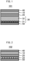
- FIG. 1 schematically shows a configuration of a secondary battery 101 according to the first embodiment.
- the secondary battery 101 comprises a positive electrode active material layer 10, a solid electrolyte layer 20, and a negative electrode active material layer 30.
- the negative electrode active material layer 30 comprises a first substance 31 and a second substance 32.
- the first substance 31 is at least one of an alloy of Li and an element X and a compound of Li and the element X.
- the second substance 32 is at least one of a simple substance of a metal element M, an alloy of Li and the metal element M, and a compound of Li and the metal element M.
- a formation energy E LiX of the first substance 31 is lower than a formation energy E MX of a compound of the metal element M and the element X.
- the positive electrode active material layer 10 comprises a positive electrode active material and may further optionally comprise an electrolyte, a conductive aid, or a binder.
- the positive electrode active material layer 10 may further comprise various additives.
- the content of each of the positive electrode active material, electrolyte, conductive aid, and binder in the positive electrode active material layer 10 may be appropriately determined according to target battery performance. For example, when the entire positive electrode active material layer 10 (total solid content) is set to 100% by mass, the content of the positive electrode active material may be 40% by mass or greater, 50% by mass or greater, or 60% by mass or greater, and may be 100% by mass or less or 90% by mass or less.
- the shape of the positive electrode active material layer 10 is not particularly limited, and may be, for example, a sheet having a substantially flat surface.
- the thickness of the positive electrode active material layer 10 is not particularly limited, and may be, for example, 0.1 ⁇ m or more, 1 ⁇ m or more, 10 ⁇ m or more, or 30 ⁇ m or more and 2 mm or less, 1 mm or less, 500 ⁇ m or less, or 100 ⁇ m or less.
- any known positive electrode active material for secondary batteries that is capable of releasing Li ions during charging and occluding Li ions during discharging may be adopted as the positive electrode active material.
- various lithium-containing oxides such as lithium cobaltate, lithium nickel oxide, LiNi 1/3 Co 1/3 Mn 1/3 O 2 , lithium manganate, and spinel-based lithium compounds can be used.
- elemental sulfur and compounds in which lithium is occluded in sulfur can be used as the positive electrode active material.
- the positive electrode active material layer 10 comprises a lithium-containing oxide as the positive electrode active material
- Li ions can be more appropriately supplied from the positive electrode active material to the negative electrode side during charging, expansion or contraction of the positive electrode active material during charging and discharging is small, and high performance can be easily obtained.
- One type of positive electrode active material may be used alone, or two or more types may be used in combination.
- the positive electrode active material may be, for example, particulate, and the size thereof is not particularly limited.
- the particles of the positive electrode active material may be solid particles, hollow particles, or particles having voids.
- the particles of the positive electrode may be primary particles, or may be secondary particles of a plurality of aggregated primary particles.
- the average particle diameter (D50) of the positive electrode active material particles may be, for example, 1 nm or more, 5 nm or more, or 10 nm or more and 500 ⁇ m or less, 100 ⁇ m or less, 50 ⁇ m or less, or 30 ⁇ m or less.
- the average particle diameter D50 as described herein is a particle diameter (median diameter) at an integrated value of 50% in a volume-based particle size distribution determined by a laser diffraction or scattering method.
- the surface of the positive electrode active material may be covered with an ion-conducting oxide.
- a composite comprising the above positive electrode active material and an ion-conducting oxide covering the surface thereof may be contained in the positive electrode active material layer 10.
- Examples of the ion-conducting oxide covering or protecting the surface of the positive electrode active material include at least one selected from Li 3 BO 3 , LiBO 2 , Li 2 CO 3 , LiAlO 2 , Li 4 SiO 4 , Li 2 SiO 3 , Li 3 PO 4 , Li 2 SO 4 , Li 2 TiO 3 , Li 4 Ti 5 O 12 , Li 2 Ti 2 O 5 , Li 2 ZrO 3 , LiNbO 3 , Li 2 MoO 4 , and Li 2 WO 4 .
- the coverage (area ratio) of the ion-conducting oxide on the surface of the positive electrode active material may be, for example, 70% or greater, 80% or greater, or 90% or greater.
- the thickness of the layer of ion-conducting oxide may be, for example, 0.1 nm or more or 1 nm or more and 100 nm or less or 20 nm or less.
- the electrolyte that can be contained in the positive electrode active material layer 10 may be a solid electrolyte, a liquid electrolyte (electrolytic solution), or a combination thereof. Particularly, when the positive electrode active material layer 10 comprises a solid electrolyte (particularly, a sulfide solid electrolyte), a greater effect can be expected from the technique of the present disclosure.
- the solid electrolyte may be an inorganic solid electrolyte or an organic polymer electrolyte. Particularly, the inorganic solid electrolyte has excellent ion-conducting property and heat resistance.
- the inorganic solid electrolyte include oxide solid electrolytes and sulfide solid electrolytes. Among the inorganic solid electrolytes, sulfide solid electrolytes, particularly sulfide solid electrolytes comprising at least Li, S, and P as constituent elements have high performance.
- the solid electrolyte may be amorphous or crystalline.
- the solid electrolyte may be, for example, particulate.
- the average particle diameter (D50) of the solid electrolyte may be, for example, 10 nm or more and 10 ⁇ m or less.
- the ion conductivity of the solid electrolyte at 25 °C may be, for example, 1 ⁇ 10 -4 S/cm or more or 1 ⁇ 10 -3 S/cm or more.
- One type of solid electrolyte may be used alone, or two or more types may be used in combination.
- the oxide solid electrolyte may be one or more selected from lithium lanthanum zirconate, LiPON, Li 1+X Al X Ge 2-X (PO 4 ) 3 , Li-SiO-based glass, and Li-Al-S-O-based glass.
- the sulfide solid electrolyte may be a glass-based sulfide solid electrolyte (sulfide glass), a glass-ceramic-based sulfide solid electrolyte, or a crystalline sulfide solid electrolyte.
- the sulfide glass is amorphous.
- the sulfide glass may have a glass transition temperature (Tg). If the sulfide solid electrolyte has a crystal phase, examples of the crystal phase include Thio-LISICON type crystal phase, LGPS type crystal phase, and argyrodite type crystal phase.
- the sulfide solid electrolyte may contain, for example, Li element, X element (X is at least one of P, As, Sb, Si, Ge, Sn, B, Al, Ga, and In), and S element.
- X is at least one of P, As, Sb, Si, Ge, Sn, B, Al, Ga, and In
- the sulfide solid electrolyte may further contain at least one of O element and a halogen element. Further, the sulfide solid electrolyte may contain S element as a main component of the anion element.
- the sulfide solid electrolyte may be, for example, at least one selected from Li 2 S-P 2 S 5 , Li 2 S-P 2 S 5 -LiI, Li 2 S-P 2 S 5 -GeS 2 , Li 2 S-P 2 S 5 -Li 2 O, Li 2 S-P 2 S 5 -Li 2 O-LiI, Li 2 S-P 2 S 5 -LiI-LiBr, Li 2 S-SiS 2 , Li 2 S-SiS 2 -LiI, Li 2 S-SiS 2 -LiBr, Li 2 S-SiS 2 -LiCl, Li 2 S-SiS 2 -B 2 S 3 -LiI, Li 2 S-SiS 2 -P 2 S 5 -LiI, Li 2 S-B 2 S 3 , Li 2 S-P 2 S 5 -ZmSn (wherein m and n are each a positive number; and Z is any of Ge
- the composition of the sulfide solid electrolyte is not particularly limited. Examples thereof include xLi 2 S•(100 - x)P 2 S 5 (70 ⁇ x ⁇ 80) and yLiI•zLiBr•(100 - y - z)(xLi 2 S•(1 - x)P 2 S 5 ) (0.7 ⁇ x ⁇ 0.8; 0 ⁇ y ⁇ 30; and 0 ⁇ z ⁇ 30).
- the sulfide solid electrolyte may have a composition represented by a general formula: Li 4-x Ge 1-x P x S 4 (0 ⁇ x ⁇ 1).
- At least a portion of Ge may be substituted with at least one of Sb, Si, Sn, B, Al, Ga, In, Ti, Zr, V, and Nb.
- at least a portion of P may be substituted with at least one of Sb, Si, B, Al, Ga, In, Ti, Zr, V, and Nb.
- a portion of Li may be substituted with at least one of Na, K, Mg, Ca, and Zn.
- a portion of S may be substituted with a halogen (at least one of F, Cl, Br, and I).
- the sulfide solid electrolyte may have a composition represented by Li 7- a PS 6- a X a (X is at least one of Cl, Br, and I; and a is a number of 0 or greater and 2 or less).
- a may be 0 or greater than 0. In case of the latter, a may be 0.1 or greater, 0.5 or greater, or 1 or greater. In addition, a may be 1.8 or less or 1.5 or less.
- the electrolytic solution can comprise, for example, lithium ions as the carrier ion.
- the electrolytic solution may be, for example, a nonaqueous electrolytic solution.
- a solution obtained by dissolving a lithium salt in a carbonate-based solvent at a predetermined concentration can be used as the electrolytic solution.
- the carbonate-based solvent include fluoroethylene carbonate (FEC), ethylene carbonate (EC), and dimethyl carbonate (DMC).
- the lithium salt include hexafluorophosphate.
- Examples of the conductive aid that can be contained in the positive electrode active material layer 10 include carbon materials such as vapor-grown carbon fiber (VGCF), acetylene black (AB), Ketjen black (KB), carbon nanotube (CNT), and carbon nanofiber (CNF); and metal materials such as nickel, aluminum, and stainless steel.
- the conductive aid may be, for example, particulate or fibrous, and the size thereof is not particularly limited.
- One type of conductive aid may be used alone, or two or more types may be used in combination.
- binder examples include butadiene rubber (BR)-based binders, butylene rubber (IIR)-based binders, acrylate-butadiene rubber (ABR)-based binders, styrene-butadiene rubber (SBR)-based binders, polyvinylidene fluoride (PVdF)-based binders, polytetrafluoroethylene (PTFE)-based binders, polyimide (PI)-based binders, and polyacrylic acid-based binders.
- BR butadiene rubber
- IIR acrylate-butadiene rubber
- SBR styrene-butadiene rubber
- PVdF polyvinylidene fluoride
- PTFE polytetrafluoroethylene
- PI polyimide
- polyacrylic acid-based binders examples include butadiene rubber (BR)-based binders, butylene rubber (IIR)-based binders, acrylate-buta
- the solid electrolyte layer 20 comprises at least a solid electrolyte.
- the solid electrolyte contained in the solid electrolyte layer 20 may be the same as or different from the solid electrolyte that can be contained in the above positive electrode active material layer 10.
- the solid electrolyte layer 20 comprises an inorganic solid electrolyte
- the inorganic solid electrolyte include the above oxide solid electrolytes and sulfide solid electrolytes.
- sulfide solid electrolytes particularly sulfide solid electrolytes comprising at least Li, S, and P as constituent elements, have high performance.
- the solid electrolyte layer 20 may further optionally comprise a binder and various additives.
- the binder that can be contained in the solid electrolyte layer 20 may be the same as or different from the binder that can be contained in the above positive electrode active material layer 10.
- the solid electrolyte layer 20 may be formed entirely of a solid, or may comprise a solid electrolyte and a liquid. The contents of the solid electrolyte and the binder in the solid electrolyte layer 20 are not particularly limited.
- the content of the solid electrolyte may be 50% by mass or greater, 60% by mass or greater, or 70% by mass or greater and 100% by mass or less or 90% by mass or less.
- the thickness of the solid electrolyte layer 20 is not particularly limited, and may be, for example, 0.1 ⁇ m or more or 1 ⁇ m or more and 2 mm or less or 1 mm or less.
- the negative electrode active material layer 30 comprises a first substance 31 and a second substance 32.
- the first substance 31 is at least one of an alloy of Li and an element X and a compound of Li and the element X.
- the second substance 32 is at least one of a simple substance of a metal element M, an alloy of Li and the metal element M, and a compound of Li and the metal element M.
- the formation energy E LiX of the first substance 31 is lower than the formation energy E MX of a compound of the metal element M and the element X.
- the secondary battery 101 after the discharging may have the same configuration as the secondary battery 102 according to the second embodiment described below.
- the secondary battery 101 may be controlled to stop discharging before reaching the same configuration as that of the secondary battery 102 according to the second embodiment described below.
- the secondary battery 101 after discharging may include a compound of the metal element M and the element X or the negative electrode active material layer 30 between the solid electrolyte layer 20 and the negative electrode current collector 50.
- Li ions are released from the positive electrode active material layer 10.
- the Li ions released from the positive electrode active material layer 10 arrive between the solid electrolyte layer 20 and the negative electrode current collector 50 via the solid electrolyte layer 20, and can be deposited as the second substance 32 or metallic lithium.
- the negative electrode active material layer 30 can be formed between the solid electrolyte layer 20 and the negative electrode current collector 50.
- the negative electrode active material layer 30 comprises the first substance 31 and the second substance 32 described above.
- the thickness of the negative electrode active material layer 30 after charging is not particularly limited, and may be, for example, 0.1 ⁇ m or more or 1 ⁇ m or more and 2 mm or less or 1 mm or less.
- the deposition amount of metallic lithium between the solid electrolyte layer 20 and the negative electrode current collector 50 is not particularly limited, and may be appropriately adjusted according to target battery performance. However, when the amount of metallic lithium deposited is excessive, there is a concern of concentration of pressure. In this regard, as a guideline for the deposition amount of metallic lithium, the amount may be such that the charge capacity of the secondary battery 101 is, for example, 1 mAh/cm 2 or more and 5 mAh/cm 2 or less.
- the first substance 31 is at least one of an alloy of Li and an element X and a compound of Li and the element X.
- the element X may form a solid solution with metallic Li, or may form a compound with metallic Li.
- the negative electrode active material layer 30 comprises a compound of Li and the element X as the first substance 31.
- the negative electrode active material layer 30 comprises an alloy of Li and the element X as the first substance 31.
- the molar ratio of Li to the element X is not particularly limited and depends on the element X and the first substance 31.
- the formation energy E LiX of the first substance 31 is lower than the formation energy E MX of a compound of the metal element M and the element X.
- the element X has a relatively high reactivity with Li and a relatively low reactivity with the metal element M.
- the element X constituting the first substance 31 is not particularly limited.
- the element X may be a metal element or a nonmetal element.
- the element X is at least one of H, B, and P, the first substance 31 has excellent lithium ion-conducting property, and the performance of the secondary battery 101 is more easily enhanced.
- the first substance 31 may be at least one selected from compounds of Li and B, compounds of Li and P, compounds of Li and H, composite compounds thereof, or mixtures thereof.
- the metal element M described below is Mg and the element X is at least one of Bi, Sb, In, Sn, H, I, Ga, Te, Hg, Cd, Si, B, As, Zn, Ge, Br, P, and Se, the performance of the secondary battery 101 is more easily enhanced.
- the shape of the first substance 31 and the position of the first substance 31 in the negative electrode active material layer 30 are not particularly limited.
- the first substance 31 may be particulate, layered (including a layer of aggregated particles), or film-like (including a film of aggregated particles), or may be of an indeterminate shape.
- the first substance 31 may be dispersed or unevenly distributed in the negative electrode active material layer 30. Particularly, when the negative electrode active material layer 30 comprises the first substance 31 formed into a film and the thickness of the first substance 31 formed into the film is 10 nm or more and 50 ⁇ m or less, high performance is easily ensured.
- the thickness may be 30 nm or more and 40 ⁇ m or less, 50 nm or more and 30 ⁇ m or less, 70 nm or more and 20 ⁇ m or less, or 100 nm or more and 10 ⁇ m or less. Further, the thickness may be 0.05% or greater and 100% or less or 1% or greater and less than 100% of the total thickness of the negative electrode active material layer 30.
- the negative electrode active material layer 30 comprises the first substance 31 formed into a film
- the first substance 31 formed into the film may be or may not be in contact with the negative electrode current collector 50.
- the first substance 31 formed into the film may be or may not be in contact with the solid electrolyte layer 20.
- the first substance 31 formed into the film when the first substance 31 formed into the film is in contact with the negative electrode current collector 50, i.e., when the first substance 31 formed into the film covers the surface of the negative electrode current collector 50, the first substance 31 functions as a protective film, and high performance is easily ensured.
- the area of the first substance 31 formed into the film may be 50% or greater, 60% or greater, 70% or greater, 80% or greater, 90% or greater, 95% or greater, or 99% or greater of the area of the negative electrode active material layer 30 (area of the surface of the negative electrode active material layer 30 facing the negative electrode current collector 50).
- the amount of the first substance 31 in the negative electrode active material layer 30 is not particularly limited.
- the negative electrode active material layer 30 may comprise greater than 0% by mass and 80% by mass or less of the first substance 31.
- the amount of the first substance 31 may be 0.01% by mass or greater and 70% by mass or less, 0.1% by mass or greater and 60% by mass or less, 1% by mass or greater and 50% by mass or less, or 10% by mass or greater and 40% by mass or less.
- the second substance 32 is at least one of a simple substance of a metal element M, an alloy of Li and the metal element M, and a compound of Li and the metal element M.
- the metal element M may be present as a single substance without being bonded to another element, may form a solid solution with metallic Li, or may form a compound with metallic Li.
- the negative electrode active material layer 30 comprises a compound of Li and the metal element M as the second substance 32.
- the negative electrode active material layer 30 comprises an alloy of Li and the metal element M as the second substance 32.
- the molar ratio of Li to the metal element M is not particularly limited and depends on the metal element M and the second substance 32.
- the formation energy E LiX of the first substance 31 is lower than the formation energy E MX of a compound of the metal element M and the element X.
- each of the first substance 31 and the second substance 32 tends to be stable in the negative electrode active material layer 30.
- a reaction between the element X constituting the first substance 31 and the metal element M constituting the second substance 32 is easily suppressed by Li.
- the metal element M constituting the second substance 32 is not particularly limited.
- the metal element M may be an element alloyable with Li.
- the metal element M is at least one of Mg, Sn, Zn, In, Al, Fe, Ni, Mn, Cr, Ag, Ga, Si, Sb, Pb, Bi, Cd, Sr, Ge, and As, particularly when the metal element M is Mg, in addition to satisfying the above relations in formation energy, deposition and dissolution reactions of Li during charging and discharging are likely to be uniform, and high performance is easily ensured.
- the second substance 32 may be elemental Mg, an alloy of Li and Mg, or a compound of Li and Mg.
- the shape of the second substance 32 and the position of the second substance 32 in the negative electrode active material layer 30 are not particularly limited.
- the second substance 32 may be particulate, layered (including an aggregation of a plurality of particles), or film-like (including an aggregation of a plurality of particles), or may be of an indeterminate shape.
- the second substance 32 may be dispersed or unevenly distributed in the negative electrode active material layer 30. Particularly, when the negative electrode active material layer 30 comprises the second substance 32 formed into a film and the thickness of the second substance 32 layer is 100 nm or more and 500 ⁇ m or less, high performance is easily ensured.
- the second substance 32 layer may or may not be in contact with the solid electrolyte layer 20. Further, the second substance 32 layer may or may not be in contact with the negative electrode current collector 50. Particularly, when the second substance 32 layer is in contact with the solid electrolyte layer 20, deposition and dissolution reactions of Li during charging and discharging are likely to be uniform, and high performance is easily ensured.
- the area of the second substance 32 layer may be 50% or greater, 60% or greater, 70% or greater, 80% or greater, 90% or greater, 95% or greater, or 99% or greater of the area of the negative electrode active material layer 30 (area of the surface of the negative electrode active material layer 30 facing the solid electrolyte layer 20).
- the amount of the second substance 32 in the negative electrode active material layer 30 is not particularly limited.
- the negative electrode active material layer 30 may comprise 1% by mass or greater and less than 100% by mass of the second substance 32.
- the metal element M and the element X satisfy the following relations (1) and (2), higher performance is easily ensured. Specifically, when the following relations (1) and (2) are satisfied, the compound of the metal element M and the element X is decomposed by the conversion reaction described below during charging of the secondary battery 101, and a reverse reaction of the conversion reaction occurs and the compound of the metal element M and the element X is easily reverted during discharging of the secondary battery 101.
- the difference E MX - E LiX between the formation energy E MX and the formation energy E LiX in the secondary battery 101 may be 0.027 eV/atom or more, 0.032 eV/atom or more, 0.050 eV/atom or more, 0.075 eV/atom or more, 0.100 eV/atom or more, 0.150 eV/atom or more, or 0.200 eV/atom or more.
- the formation energies E MX , E LiM , and E LiX can be verified with various databases.
- the negative electrode active material layer 30 may comprises additional components in addition to the above first substance 31 and second substance 32.
- the negative electrode active material layer 30 may comprise a compound of the metal element M and the element X as an unreacted product of the conversion reaction described below.
- the negative electrode active material layer 30 can comprise metallic lithium deposited during charging.
- the "metallic lithium” herein is a concept which includes not only elemental lithium but also lithium alloys. That is, the negative electrode active material layer 30 may comprise elemental lithium or a lithium alloy. Examples of the lithium alloy includes the above second substance 32.
- the negative electrode active material layer 30 may comprise, for example, at least one lithium alloy selected from Li-Au, Li-Mg, Li-Sn, Li-Al, Li-B, Li-C, Li-Ca, Li-Ga, Li-Ge, Li-As, Li-Se, Li-Ru, Li-Rh, Li-Pd, Li-Ag, Li-Cd, Li-In, Li-Sb, Li-Ir, Li-Pt, Li-Hg, Li-Pb, Li-Bi, Li-Zn, Li-Tl, Li-Te, and Li-At, in addition to the above second substance 32.
- the lithium alloy may be of one type only or two or more types.
- the secondary battery 101 includes at least the above features, additional features other than those above may be included.
- the features described below are examples of additional features that can be included in the secondary battery 101.
- the secondary battery 101 may comprise a positive electrode current collector 40 in contact with the positive electrode active material layer 10.
- Any positive electrode current collector that can function as a positive electrode current collector for secondary batteries can be adopted as the positive electrode current collector 40.
- the positive electrode current collector 40 may be a metal foil or a metal mesh. Particularly, a metal foil has excellent handleability.
- the positive electrode current collector 40 may be composed of a plurality of metal foils. Examples of the metal constituting the positive electrode current collector 40 include Cu, Ni, Cr, Au, Pt, Ag, Al, Fe, Ti, Zn, Co, and stainless steel. Particularly, from the viewpoint of ensuring oxidation resistance, the positive electrode current collector 40 may comprise Al.
- the positive electrode current collector 40 may have some coating layer on the surface thereof for the purpose of adjusting resistance and etc. Further, when the positive electrode current collector 40 is composed of a plurality of metal foils, some layer may be included between the plurality of metal foils.
- the thickness of the positive electrode current collector 40 is not particularly limited. For example, the thickness thereof may be 0.1 ⁇ m or more or 1 ⁇ m or more, and may be 1 mm or less or 100 ⁇ m or less.
- the secondary battery 101 may comprise a negative electrode current collector 50 in contact with the negative electrode active material layer 30.
- Any negative electrode current collector that can function as a negative electrode current collector for secondary batteries can be adopted as the negative electrode current collector 50.
- the negative electrode current collector 50 may be a metal foil or a metal mesh, or may be a carbon sheet. Particularly, a metal foil has excellent handleability.
- the negative electrode current collector 50 may be composed of a plurality of metal foils or sheets. Examples of the metal constituting the negative electrode current collector 50 include Cu, Ni, Cr, Au, Pt, Ag, Al, Fe, Ti, Zn, Co, and stainless steel.
- the negative electrode current collector 50 may comprise at least one metal selected from Cu, Ni, and stainless steel, particularly at least one metal from Ni and stainless steel.
- the negative electrode current collector 50 may have some coating layer on the surface thereof. Further, when the negative electrode current collector 50 is composed of a plurality of metal foils, some layer may be included between the plurality of metal foils.
- the thickness of the negative electrode current collector 50 is not particularly limited. For example, the thickness thereof may be 0.1 ⁇ m or more or 1 ⁇ m or more, and may be 1 mm or less or 100 ⁇ m or less.
- the negative electrode current collector 50 may have some protective layer on the surface thereof.
- the above negative electrode current collector 50 may have a conductive substrate selected from the above metal foil, metal mesh, or carbon sheet and a protective layer formed on a surface of the conductive substrate, and the protective layer may be disposed between the conductive substrate and the above negative electrode active material layer 30.
- the protective layer for example, may comprise Mg and may not comprise a compound of Mg and the element X.
- a negative electrode current collector 50 having a protective layer comprising Mg By including a negative electrode current collector 50 having a protective layer comprising Mg, it is considered that in addition to promoting diffusion of Li on the surface of the negative electrode current collector 50, affinity of metallic lithium for the negative electrode current collector 50 is increased, voids between the negative electrode current collector 50 and metallic lithium are suppressed, and metallic lithium is deposited more uniformly on the surface of the negative electrode current collector 50.
- the protective layer may have the highest molar ratio of Mg among all constituent elements thereof.
- the molar ratio of Mg in the entire protective layer may be, for example, 50 mol% or greater and 100 mol% or less, and may be 70% mol% or greater, 80 mol% or greater, or 90 mol% or greater.
- the protective layer may be, for example, one of a metal thin film (for example, a vapor deposition film) containing Mg or a layer comprising Mg particles.
- the protective layer may be a layer containing only Mg particles.
- the metal thin film containing Mg can be composed of Mg or a Mg alloy.
- the Mg particles may be particles of elemental Mg, or may be particles containing Mg and an element other than Mg.
- the Mg particles may be alloy particles (Mg alloy particles) containing Mg and a metal other than Mg.
- the Mg alloy particles may be an alloy containing Mg as the main component (an alloy in which Mg is 50 mol% or greater of all constituent elements).
- the Mg alloy particles may comprise at least one of Li, Au, Al, and Ni as the metal M other than Mg.
- the Mg alloy particles may or may not contain Li.
- the Mg alloy particles may comprise a ⁇ single phase Li-Mg alloy.
- the Mg particles may be oxide particles (Mg oxide particles) containing Mg and O.
- the Mg oxide particles may be particles of an oxide consisting only of Mg and O, or may be particles of a composite oxide represented by Mg-M'-O (M' is at least one of Li, Au, Al, and Ni).
- Mg-M'-O Mg-M'-O
- M' is at least one of Li, Au, Al, and Ni.
- M' may or may not contain a metal other than Li. In the former case, M' may be of one metal other than Li or two or more thereof.
- the Mg particles may be primary particles, or may be secondary particles of a plurality of aggregated primary particles.
- the average particle diameter (D50) of the Mg particles may be, for example, 100 nm or more and 100 ⁇ m or less, may be 200 nm or more, 300 nm or more, 400 nm or more, 500 nm or more, 600 nm or more, 700 nm or more, or 800 nm or more, and may be 50 ⁇ m or less, 40 ⁇ m or less, 30 ⁇ m or less, 20 ⁇ m or less, 10 ⁇ m or less, 5 ⁇ m or less, or 3 ⁇ m or less.
- the thickness of the protective layer may be, for example, 10 nm or more and 10 ⁇ m or less.
- the thickness of the protective layer may be 50 nm or more or 100 nm or more, and may be 5 ⁇ m or less, 3 ⁇ m or less, 1 ⁇ m or less, or 700 nm or less.
- the negative electrode current collector 50 may not be provided with a protective layer, may be provided with one protective layer, or may be provided with two or more layers. Examples of a formation method of the protective layer include a method of film-forming a protective layer on the surface on the above conductive substrate constituting the negative electrode current collector 50 and a method of pressing Mg particles.
- a PVD method such as vapor deposition or sputtering
- a plating method such as electroplating or electroless plating
- an application method using a slurry can be adopted.
- each of the above components may be housed inside an outer packaging. More specifically, portions excluding tabs or terminals for outputting electric power from the secondary battery 101 to the outside may be housed inside the outer packaging.
- Any outer packaging known as an outer packaging for batteries can be adopted.
- a laminate film may be used as an outer packaging.
- a plurality of secondary batteries 101 may be electrically connected and optionally stacked to form a battery pack. In this case, the battery pack may be housed inside a known battery pack case.
- Each of the above components may be sealed with a resin in the secondary battery 101.
- a resin in the secondary battery 101 For example, at least side surfaces (surfaces along stacking direction) of each layer shown in FIG. 1 may be sealed with a resin. As a result, entry of moisture into the inside of each layer is more easily suppressed. Any known curable resin or thermoplastic resin can be adopted as the sealing resin.
- the secondary battery 101 may include a restraining member for restraining each of the above member in the thickness direction.
- a restraining pressure By applying a restraining pressure with the restraining member, internal resistance of the battery is easily decreased.
- the restraining pressure by the restraining member is not particularly limited.
- the restraining pressure by the restraining member may be 5 MPa or less, 3 MPa or less, or 1 MPa or less.
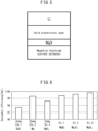
- FIG. 2 shows a configuration of a secondary battery 102 according to the second embodiment.
- the secondary battery 102 comprises a positive electrode active material layer 10, a solid electrolyte layer 20, a negative electrode current collector 50, and metallic lithium deposited between the solid electrolyte layer 20 and the negative electrode current collector 50 by charging.
- a compound 33 of a metal element M and an element X is present between the solid electrolyte layer 20 and the negative electrode current collector 50.
- the formation energy E MX of the compound 33 of the metal element M and the element X is higher than the formation energy E LiX of a compound (corresponding to the first substance 31 of the first embodiment above) of Li and the element X.
- the positive electrode active material layer 10, the solid electrolyte layer 20, and the negative electrode current collector 50 may be the same as those of the first embodiment. As shown in FIG. 3 , during charging of the secondary battery 102, Li ions released from the positive electrode active material layer 10 arrive between the solid electrolyte layer 20 and the negative electrode current collector 50 via the solid electrolyte layer 20 and are deposited as metallic lithium by accepting electrons. During discharging of the battery, the metallic lithium between the solid electrolyte layer 20 and the negative electrode current collector 50 is dissolved (ionized) and returns to the positive electrode active material layer 10.
- the secondary battery 102 comprise a lithium deposition-type negative electrode. Specifically, as shown in FIGS. 2 and 3 , metallic lithium is deposited between the solid electrolyte layer 20 and the negative electrode current collector 50 by charging. The metallic lithium deposited between the solid electrolyte layer 20 and the negative electrode current collector 50 is dissolved (ionized) during discharging and returns to the positive electrode active material layer 10.
- the "metallic lithium” herein is a concept which includes not only elemental lithium but also lithium alloys. Specifically, in the secondary battery 102, metallic lithium may be deposited as elemental lithium or as an alloy with another metal. Specific examples of the lithium alloy are as described above.
- a predetermined compound 33 is present between the solid electrolyte layer 20 and the negative electrode current collector 50.
- lithium supplied from the positive electrode active material layer 10 to between the solid electrolyte layer 20 and the negative electrode current collector 50 causes a conversion reaction of the compound 33, a compound or alloy (corresponding to first substance 31) of lithium and the element X is generated while a fresh metal M (corresponding to second substance 32) is generated, the fresh metal M and lithium are alloyed, and a lithium alloy (corresponding to second substance 32) as the metallic lithium or a compound (corresponding to second substance 32) of the metal element M and Li can be deposited.
- the compound 33 of the metal element M and the element X is present between the solid electrolyte layer 20 and the negative electrode current collector 50.
- the formation energy E MX of the compound 33 of the metal element M and the element X is higher than the formation energy E LiX of the compound (corresponding to first substance 31) of Li and the element X.
- a compound of Li and the element X is more easily generated than a compound 33 of the metal element M and the element X.
- the compound 33 present between the solid electrolyte layer 20 and the negative electrode current collector 50 is decomposed by a conversion reaction as represented by the following reaction equation (1) to form a compound (corresponding to first substance 31) of Li and the element X and a fresh metal M (corresponding to second substance 32).
- the fresh metal element M and Li cause a reaction as indicated in the following reaction equation (2), and a lithium alloy (corresponding to first substance 31) as the metallic lithium or a compound (corresponding to second substance 32) of the metal element M and Li is deposited.
- the metal element M may be any element as long as the above relation in formation energy is satisfied and the above conversion reaction can proceed.
- the metal element M may be an element alloyable with Li.
- the metal element M is at least one of Mg, Sn, Zn, In, Al, Fe, Ni, Mn, Cr, Ag, Ga, Si, Sb, Pb, Bi, Cd, Sr, Ge, and As, particularly when the metal element M is Mg, deposition and dissolution reactions of Li during charging and discharging are likely to be uniform, and high performance is easily ensured.
- the element X may also be any element as long as the above relation in formation energy is satisfied and the above conversion reaction can proceed.
- the element X may be a metal element or a nonmetal element. Particularly, when the product (first substance 31) after the conversion reaction has excellent lithium ion-conducting property, the performance of the secondary battery is more easily enhanced. In consideration of a more efficient conversion reaction and generation of a product having excellent lithium ion-conducting property, the element X may be at least one of H, B, and P.
- the metal element M is Mg
- the element X is at least one of Bi, Sb, In, Sn, H, I, Ga, Te, Hg, Cd, Si, B, As, Zn, Ge, Br, P, and Se, higher performance is easily ensured.
- the compound 33 of the metal element M and the element X may be at least one selected from compounds of Mg and B (for example, magnesium diboride: MgB 2 ), compounds of Mg and P (for example, magnesium phosphide: Mg 3 P 2 ), compounds of Mg and H (for example, magnesium hydride: MgH 2 ), composite compounds thereof, and mixtures thereof.
- MgB 2 magnesium diboride: MgB 2
- Mg and P for example, magnesium phosphide: Mg 3 P 2
- compounds of Mg and H for example, magnesium hydride: MgH 2
- composite compounds thereof and mixtures thereof.
- the metal element M and the element X satisfy the following relations (1) and (2), higher performance is easily ensured. Specifically, when the following relations (1) and (2) are satisfied, a compound of the metal element M and the element X is decomposed by the above conversion reaction during charging of the secondary battery 102, and a reverse reaction of the conversion reaction occurs and the compound of the metal element M and the element X is easily reverted during discharging of the secondary battery 102.
- the shape of the compound 33 of the metal element M and the element X is not particularly limited, and may be of a thin film or layer, may be particulate, or may be of a layer comprising the compound 33 in particulate form. As described in detail in the manufacturing method of the secondary batteries 101 and 102, the compound 33 may cover the surface of the negative electrode current collector 50. In addition, as shown in FIG. 2 , the compound 33 may be in contact with the solid electrolyte layer 20 before the conversion reaction.
- the average particle diameter (D50) thereof may be, for example, 100 nm or more and 100 ⁇ m or less, and may be 200 nm or more, 400 nm or more, 600 nm or more, 800 nm or more, 1 ⁇ m or more, 5 ⁇ m or more, or 10 ⁇ m or more and 90 ⁇ m or less, 80 ⁇ m or less, 70 ⁇ m or less, 60 ⁇ m or less, or 50 ⁇ m or less.
- the amount of the compound 33 between the solid electrolyte layer 20 and the negative electrode current collector 50 is not particularly limited, and may be appropriately determined in consideration of battery performance.
- the thickness thereof may be 10 nm or more and 100 ⁇ m or less, and may be 20 nm or more, 30 nm or more, 40 nm or more, 100 nm or more, 200 nm or more, 400 nm or more, 600 nm or more, 800 nm or more, 1 ⁇ m or more, 5 ⁇ m or more, or 10 ⁇ m or more and 90 ⁇ m or less, 80 ⁇ m or less, 70 ⁇ m or less, 60 ⁇ m or less, 50 ⁇ m or less, 40 ⁇ m or less, 30 ⁇ m or less, 20 ⁇ m or less, 10 ⁇ m or less, 1 ⁇ m or less, or 800 nm or less.
- the number of particles in the thickness direction of the layer may be 1
- the difference E MX - E LiX between the formation energy E MX and the formation energy E LiX in the secondary battery 102 may be 0.027 eV/atom or more, 0.032 eV/atom or more, 0.050 eV/atom or more, 0.075 eV/atom or more, 0.100 eV/atom or more, 0.150 eV/atom or more, or 0.200 eV/atom or more.
- a compound of Li and the element X can be generated by a conversion reaction of the compound 33 of the metal element M and the element X in the secondary battery 102.
- the type of the compound of Li and the element X depends on the type of the compound 33.
- the compound of Li and the element X may be at least one selected from compound of Li and B, compounds of Li and P, compounds of Li and H, composite compounds thereof, and mixtures thereof.
- the shape of the compound of Li and the element X depends on the shape of the compound 33.
- the shape of the compound of Li and the element X may be of a thin film or layer, may be particulate, or may be of a layer comprising the compound in particulate form, as described above.
- the amount of the compound of Li and the element X between the solid electrolyte layer 20 and the negative electrode current collector 50 after the conversion reaction depends on the amount of the compound 33.
- the compound of Li and the element X for example, may cover the surface of the negative electrode current collector 50 to protect the negative electrode current collector 50.
- the secondary battery 102 may comprise a positive electrode current collector 40.
- the secondary battery 102 may comprise a predetermined outer packaging.
- the secondary battery 102 may comprise a predetermined sealing resin.
- the secondary battery 102 may comprise a predetermined restraining member.
- the second substance 32 releases Li ions, and a fresh metal M is generated accordingly.
- the fresh metal M functions as a deposition site for metallic lithium (second substance 32) during charging of the secondary battery 101, and metallic lithium is likely to be deposited uniformly, gradually, and efficiently. By suppressing uneven deposition of metallic lithium, the secondary battery 101 has excellent coulombic efficiency.
- the first substance 31 may release Li ions or may remain as the first substance 31. When the first substance 31 releases Li ions, the remaining portion of the element X can react with the above fresh metal M.
- a compound 33 (MX) of the metal element M and the element X may be generated.
- the compound 33 can react with Li ions during charging of the secondary battery 101 to cause the above conversion reaction, and a first substance 31 (LiX) and a fresh metal M can be generated.
- the fresh metal M as described above, functions as a deposition site for metallic lithium, and metallic lithium (second substance 32) is deposited uniformly and gradually during charging of the secondary battery 101.
- a fresh metal M that acts as a deposition site for metallic lithium during charging is contained in a negative electrode active material layer 30.
- metallic lithium Li-M alloy
- the affinity of the deposited Li for the solid electrolyte layer 20 is increased, and formation of voids at the interface between the solid electrolyte layer 20 and the deposited Li is easily suppressed. Further, voids in the negative electrode active material layer 30 are easily suppressed. By suppressing uneven deposition of metallic lithium, a secondary battery 101 having excellent coulombic efficiency is obtained.
- the compound 33 of the metal element M and the element X reacts with Li ions, a fresh metal M can be generated between the solid electrolyte layer 20 and the negative electrode current collector 50 (for example, the interface between the solid electrolyte layer 20 and the compound 33 or the interface between the solid electrolyte layer 20 and the compound (first substance 31) of Li and the element X) by the above conversion reaction, and metallic lithium can be deposited uniformly, gradually, and efficiently on the fresh metal M between the solid electrolyte layer 20 and the negative electrode current collector 50 as a starting point.
- voids between the solid electrolyte layer 20 and the negative electrode current collector 50 during deposition of metallic lithium can be suppressed.
- the affinity of metallic lithium for the solid electrolyte layer 20 is easily increased, and voids at the interface between the solid electrolyte layer 20 and the metallic lithium can be suppressed.
- voids between the solid electrolyte layer 20 and the negative electrode current collector 50 reaction irregularity during charging and discharging is eliminated, and coulombic efficiency for the secondary battery is easily improved.
- LiX and a fresh metal M are generated between the solid electrolyte layer 20 and negative electrode current collector 50 by the above conversion reaction, a layer composed of LiX and the fresh metal M and having a storage structure is formed, whereby a decrease in volume change of the secondary battery during charging and discharging can be expected.
- the secondary batteries 101 and 102 can be specified from the viewpoint of the functions thereof, as follows.
- the secondary battery 101 according to the first embodiment may be configured so that, for example, the element X of the first substance 31 and the metal element M of the second substance 32 react with each other during discharging to generate a compound 33 of the metal element M and the element X. More specifically, the secondary battery 101 may be configured so that the element X of the first substance 31 and the metal element M of the second substance 32 react with each other during discharging to generate a compound 33 of the metal element M and the element X on one or both of the surface of the solid electrolyte layer 20 and the surface of the negative electrode current collector 50.
- the secondary battery 101 can be configured so that the element X of the first substance 31 and the metal element M of the second substance 32 react with each other during discharging to generate a compound 33 of the metal element M and the element X on the surface of the negative electrode current collector 50.
- the secondary battery 102 according to the second embodiment may be configured so that, for example, the compound 33 of the metal element M and the element X decomposes during charging to generate a compound of Li and the element X. More specifically, the secondary battery 102 may be configured so that the compound 33 of the metal element M and the element X decomposes during charging to generate a compound of Li and the element X on one or both of the surface of the solid electrolyte layer 20 and the surface of the negative electrode current collector 50. In one embodiment, the secondary battery 102 can be configured so that the compound 33 of the metal element M and the element X decomposes during charging to generate a compound (first substance 31) of Li and the element X on the surface of the negative electrode current collector 50.
- the secondary battery of the present disclosure can be said to have different structures before and after the conversion reaction.
- a compound 33 of a metal element M and an element X may be present between the solid electrolyte layer 20 and the negative electrode current collector 50 before the conversion reaction (for example, before charging)
- an alloy or compound (first substance 31) of Li and an element X may be present between the solid electrolyte layer 20 and the negative electrode current collector 50 after the conversion reaction (for example, after charging).
- a secondary battery after the conversion reaction has the same configuration as the secondary battery 101 according to the first embodiment above
- a secondary battery before the conversion reaction has the same configuration as the secondary battery 102 according to the second embodiment above.
- the manufacturing method for a secondary battery 101 or 102 may comprise: obtaining a laminated body 70 comprising a positive electrode active material layer 10, a solid electrolyte layer 20, a negative electrode current collector 50, and a compound 33 of a metal element M and an element X disposed between the solid electrolyte layer 20 and the negative electrode current collector 50; and charging the laminated body 70 to supply lithium ions between the solid electrolyte layer 20 and the negative electrode current collector 50 to cause a conversion reaction of the compound 33 of the metal element M and the element X to generate a first substance 31 and a second substance 32.
- the first substance 31 is at least one of an alloy of Li and an element X and a compound of Li and the element X
- the second substance 32 is at least one of a simple substance of a metal element M, an alloy of Li and the metal element M, and a compound of Li and the metal element M.
- the laminated body 70 may be obtained as follows. Specifically, the manufacturing method of the present disclosure may comprise covering a surface of the negative electrode current collector 50 with a compound 33 of the metal element M and the element X to obtain a covered product 60, and laminating a positive electrode current collector 40, the positive electrode active material layer 10, the solid electrolyte layer 20, and the covered product 60 together to obtain the laminated body 70.
- a surface of the negative electrode current collector 50 may be covered with a compound 33 of a metal element M and an element X to obtain a covered product 60.
- the negative electrode current collector 50 can optionally have a protective layer, as described above.
- the method of covering the surface of the negative electrode current collector 50 with the compound 33 is not particularly limited.
- the negative electrode current collector 50 can be covered with the compound 33 by an application method using a solution or slurry.
- the compound 33 may be transferred from the transfer material to the surface of the negative electrode current collector 50.
- the surface of the negative electrode current collector 50 may be covered with the compound 33 by, for example, sputtering.
- the metal element M and the element X are as described above.
- the metal element M may be Mg.
- the element X may be at least one of Bi, Sb, In, Sn, H, I, Ga, Te, Hg, Cd, Si, B, As, Zn, Ge, Br, P, and Se, or may be at least one of H, B, and P.
- a laminated body 70 comprising a positive electrode active material layer 10, a solid electrolyte layer 20, a compound 33, and a negative electrode current collector 50 in this order may be obtained using the above covered product 60 in the manufacturing method according to the present embodiment.
- the laminated body 70 may comprise a positive electrode current collector 40 in contact with the positive electrode active material layer 10.
- the laminated body 70 is easily obtained by, for example, molding and laminating the positive electrode current collector 40, the positive electrode active material layer 10, the solid electrolyte layer 20, the compound 33, and the negative electrode current collector 50 described above in this order by application, transfer, adhesion, or compression.
- the laminated body 70 may comprise at least one layer of each of the positive electrode current collector 40, the positive electrode active material layer 10, the solid electrolyte layer 20, the compound 33, and the negative electrode current collector 50.
- the laminated body 70 may comprise at least one laminated unit of the positive electrode current collector 40, the positive electrode active material layer 10, the solid electrolyte layer 20, the compound 33, and the negative electrode current collector 50 described above, or may comprise a plurality of the laminated units.
- a plurality of laminated units may be electrically connected in series or in parallel, or may not be electrically connected.
- the laminated body 70 before charging which will be described below, can adopt the same configuration as that of the secondary battery 102 according to the second embodiment.
- pressure may be applied in the thickness direction (laminating direction) to each layer or the laminated body 70 described above.
- the layers forming the laminated body 70 may be integrated by pressing, and the interfacial resistance may be decreased by eliminating gaps between the layers forming the laminated body 70.
- Each layer or the laminated body 70 can be compressed by a known means.
- each layer or the laminated body 70 can be compressed in the laminating direction by various compression methods such as CIP, HIP, roll pressing, uniaxial pressing, and mold pressing.
- the magnitude of the pressure applied to each layer or the laminated body 70 in the laminating direction can be appropriately determined according to the target battery performance.
- the pressure may be 100 MPa or more, 150 MPa or more, 200 MPa or more, 250 MPa or more, 300 MPa or more, or 350 MPa or more, from the viewpoint of plastically deforming the sulfide solid electrolyte to easily carry out the integration and gap elimination described above.
- the compression time and compression temperature of each layer or the laminated body 70 are not particularly limited.
- the laminated body 70 obtained as described above undergoes charging to deposit metallic lithium between the solid electrolyte layer 20 and the negative electrode current collector 50.
- the laminated body 70 by charging the laminated body 70, lithium ions are conducted from the positive electrode active material contained in the positive electrode active material layer 10 to the negative electrode current collector 50 side via the solid electrolyte layer 20, and the lithium ions accept electrons and are deposited as metallic lithium between the solid electrolyte layer 20 and the negative electrode current collector 50.
- the charging may be, for example, the initial charging after the laminated body 70 is prepared.
- the laminated body 70 may be charged by the same method as a general battery charging method. Specifically, an external power source may be connected to the positive electrode current collector 40 and the negative electrode current collector 50 of the laminated body 70 to carry out charging.
- the above laminated body 70 after charging can adopt the same configuration as the secondary battery 101 according to the first embodiment.
- the manufacturing method according to the present embodiment may comprise general steps for manufacturing a secondary battery, in addition to the steps described above.
- the general steps include a step of housing the laminated body 70 inside an outer packaging such as a laminate film and a step of connecting current collector tabs to the laminated body 70.
- the laminate film may be sealed with tabs pulled out to outside the laminate film, followed by charging of the laminated body 70 via the tabs outside the laminate film.
- the manufacturing method according to the present embodiment may comprise selecting a compound 33 of a metal element M and an element X, and may comprise verifying that the metal element M and the element X satisfy the following relations (1) and (2) when selecting the compound 33 of the metal element M and the element X. As a result, a more suitable compound 33 can be efficiently selected. Each formation energy can be verified, for example, with various databases.
- Vehicle comprising secondary battery
- the secondary battery of the present disclosure can suppress voids in the negative electrode active material layer and has excellent coulombic efficiency.
- a secondary battery can be suitably used, for example, in at least one type of vehicle selected from hybrid electric vehicle (HEV), plug-in hybrid electric vehicle (PHEV), and battery electric vehicle (BEV).
- HEV hybrid electric vehicle
- PHEV plug-in hybrid electric vehicle
- BEV battery electric vehicle
- the technique of the present disclosure has an aspect as a vehicle having a secondary battery, wherein the secondary battery comprises the following configuration (A) or (B):
- the technique of the present disclosure also has an aspect as a conditioning method of a secondary battery.
- the conditioning method of the present disclosure comprises preparing a secondary battery comprising a positive electrode active material layer, a solid electrolyte layer, a negative electrode current collector, and a compound of a metal element M and an element X disposed between the solid electrolyte layer and the negative electrode current collector; and charging the secondary battery to supply lithium ions between the solid electrolyte layer and the negative electrode current collector to cause a conversion reaction of the compound of the metal element M and the element X to generate a compound of Li and the element X.
- coulombic efficiency of the secondary battery can be increased.
- a powder composed of MgX was pulverized in a mortar for 10 min and classified with a 40- ⁇ m classifier.
- 350 mg of mesitylene, 22 mg of a mesitylene solution with 5 wt% styrene-butadiene rubber (SBR), and 200 mg of the MgX powder were then charged in a container and dispersed for 30 s with an ultrasonic dispersion apparatus. Subsequently, the dispersion was mixed for 3 min with a shaker and further dispersed for 30 s with an ultrasonic dispersion apparatus to obtain a MgX slurry.
- SBR wt% styrene-butadiene rubber
- a Ni foil as a negative electrode current collector was adhered to a glass substrate, and the MgX slurry was then evenly applied to the surface of the Ni foil with an applicator to obtain an MgX-coated current collector.
- the thickness of the MgX layer was 10 ⁇ m, and the basis weight was 0.2 mg/cm 2 .
- one of MgF 2 , MgB 2 , Mg 3 P 2 , and MgH 2 was adopted as MgX.
- Mg was vapor-deposited on a surface of a Ni foil to obtain a Mg-coated current collector (Mg-Ni foil).
- the thickness of the Mg layer was 700 nm.
- a Ni foil not coated with MgX or Mg was prepared.
- a Li metal layer, a solid electrolyte layer, and the above current collector were laminated to obtain an evaluation cell.
- 101.7 mg of a sulfide-based solid electrolyte Li 2 S-P 2 S 5 -based material comprising LiBr and LiI
- the negative electrode current collector was then set under the solid electrolyte layer and compression-molded at a pressure of 1 ton/cm 2 to obtain a laminated body of a solid electrolyte layer and a negative electrode current collector.
- a Li foil was set above the solid electrolyte layer of the laminated body and compression-molded, followed by restraining at 2 N•m to obtain an evaluation cell.
- MgF 2 -coated current collector MgF 2 -coated Ni foil
- MgB 2 -coated current collector MgB 2 -coated Ni foil
- Mg 3 P 2 -coated current collector Mg 3 P 2 -coated Ni foil
- MgH 2 -coated current collector MgH 2 -coated Ni foil
- the evaluation cell was left to stand in a thermostatic chamber at 60 °C for 3 h to uniformize the cell temperature.
- the evaluation cell was charged at a constant current at a current density of 435 ⁇ A/cm 2 to deposit Li, and charging was stopped when the charge capacity reached 4.35 mAh/cm 2 .
- discharging was carried out at a constant current at a current density of 435 ⁇ A/cm 2 to dissolve Li, and discharging was terminated when reached 1.0 V.
- Coulombic efficiency of each evaluation cell was determined from the following formula.
- the nucleation overvoltage was measured by reading the maximum voltage when Li was deposited up to a capacity of 1 mAh.
- the nucleation overvoltage in the first charge/discharge cycle and the nucleation overvoltage in the second cycle were each determined.
- Table 1 below and FIG. 6 show the coulombic efficiency [%] of each evaluation cell.
- Examples 1 to 3 in which ⁇ E is a positive value, have an improved coulombic efficiency over Comparative Examples 1 and 2, which do not comprise MgX, and Comparative Example 3, in which ⁇ E is a negative value. It is considered that when ⁇ E is a positive value, a conversion reaction of MgX occurs during charging of an evaluation cell and LiX and fresh Mg are generated.
- metallic lithium Li-Mg alloy
- Example 1 to 3 metallic lithium (Li-Mg alloy) was uniformly deposited between the solid electrolyte layer and the negative electrode current collector and formation of voids were suppressed due to the fresh Mg.
- Comparative Example 1 not comprising Mg or MgX, presumably since metallic lithium was unevenly deposited between the solid electrolyte layer and the negative electrode current collector, coulombic efficiency deteriorates significantly.
- Comparative Example 2 comprising Mg, presumably since Mg was present between the solid electrolyte layer and the negative electrode current collector, the Li-Mg alloy as the metallic lithium could be uniformly deposited between the solid electrolyte layer and the negative electrode current collector during charging, and coulombic efficiency was thereby improved.
- Comparative Example 3 in which ⁇ E is a negative value, coulombic efficiency was higher than in Comparative Example 1 not comprising Mg or MgX but lower than in Comparative Example 2 comprising Mg. Presumably, in Comparative Example 3, the conversion reaction of MgX did not proceed and MgX, which is disadvantageous to cell reactions, was present even after charging.
- Comparative Example 2 has lower deposition overvoltages than Comparative Example 1.
- a low deposition overvoltage means that the energy barrier for depositing metallic lithium is small and the smaller the deposition overvoltage, the more easily metallic lithium is uniformly deposited, and in turn the more easily coulombic efficiency is increased. From Comparative Example 2, it was found that deposition overvoltage can be kept low by an alloying reaction between Mg and Li. Particularly, the deposition overvoltage tends to further decrease after a second cycle when cell reactions are stabilized. In the same manner as in Comparative Example 2, the deposition overvoltages in Examples 1 to 3 decreased remarkably after the second cycle.
- Examples 1 to 3 presumably, the conversion of MgX proceeded in the first cycle, fresh elemental Mg was generated, and metallic lithium was uniformly deposited on the elemental Mg as a starting point from the second cycle onward. Similar to the results of formation energy difference ⁇ E shown in Table 1, from the results of Table 2, it can be said that conversion reaction proceeded in Examples 1 to 3. As shown in Table 2, in Comparative Example 3, the deposition overvoltage decreased slightly from the second cycle onward, but the deposition overvoltage remained high. The formation energy difference ⁇ E is also small, as shown in Table 1. Thus, it is considered that the conversion reaction did not proceed in Comparative Example 3.
- FIG. 7 shows the results of Comparative Example 3
- FIGS. 8 and 9 show the results of Example 3.
- Example 3 there was a significant change in Mg distribution in the cell cross-section before and after charging in Example 3. Specifically, it was found that Mg diffused into the metallic lithium deposited after charging. Specifically, it was found that in Example 3, the conversion reaction of MgH 2 proceeded during charging, fresh Mg was generated, which acted as a starting point for deposition of metallic lithium, and a Li-Mg alloy was deposited.
- Example 3 there is a region between the S-containing region (corresponding to a solid electrolyte layer) and the Ni-containing region (corresponding to a negative electrode current collector) in which none of Ni, Mg, and S are present, and presumably LiH generated by a conversion reaction exists there.
- Examples 1 and 2 presumably, a conversion reaction occurred during charging and a Li-Mg alloy was deposited on fresh Mg as a starting point, in the same manner as in Example 3. From FIG. 9 , it can be seen that LiH is a thin film, and the thickness thereof is 10 nm or more and 50 ⁇ m or less.
- E LiM The formation energy (E LiM ) of an alloy of Li and Mg (Li-Mg) is -0.061 [eV/atom]. Comparing the E LiM , E LiX shown in the above Table 1, and E MX shown in the above Table 1, it was found that the metal element M (Mg) and the element X adopted in Examples 1 to 3 satisfy the following relations (1) and (2).
- Example 3 The above evaluation cell according to Example 3 was charged (Li deposition) at a constant current at 490 ⁇ A/cm 2 for 6 h, the cell was then disassembled, and XRD measurement was carried out targeting the interface between the solid electrolyte layer and the deposited Li.
- the XRD measurement conditions are as described below. The results are shown in FIG. 11 .
- a Li metal layer, a MgH 2 -transferred solid electrolyte layer, and an uncoated current collector were laminated to obtain an evaluation cell having the configuration shown in FIG. 5 .
- 101.7 mg of a sulfide solid electrolyte Li 2 S-P 2 S 5 -based material comprising LiBr and LiI
- a layer composed of MgH 2 was then laminated on the surface of the solid electrolyte layer and compression-molded at a pressure of 2 ton/cm 2 to transfer the layer composed of MgH 2 to the surface of the solid electrolyte layer.
- a negative electrode current collector was set under the MgH 2 layer and compression-molded at a pressure of 6 ton/cm 2 to obtain a laminated body of a solid electrolyte layer, a MgH 2 layer, and a negative electrode current collector.
- a Li foil was further set above the solid electrolyte layer of the laminated body and compression-molded, followed by restraining at 2 N•m to obtain an evaluation cell according to Example 4.
- the obtained evaluation cell was charged at a constant current at 490 ⁇ A/cm 2 for 5 h to deposit Li, a fracture surface was obtained, and thereafter a cross-sectional observation by SEM-EDX was carried out.
- the results are shown in FIG. 12 .
- the presence of LiH at the interface between the solid electrolyte layer and the Li-Mg layer was verified.
- the coulombic efficiency of the evaluation cell was measured in the same manner as above, the same level of coulombic efficiency as in Example 3 was obtained. From this result, it is considered that the position of LiX (LiH) in the negative electrode active material layer is not particularly restricted.
- H, B, and P were exemplified above as the element X, the element X is not limited thereto. Referring to formation energies in the Materials Project database, elements other than H, B, and P applicable as the element X were extracted. Examples of positive values of ⁇ E described above are shown in Table 3 below. ⁇ E of the elements H, B, and P are also listed for reference. When an element exemplified below is adopted as the element X, the same effect as in Examples 1 to 3 is presumably exhibited.
- the metal element M is not limited to Mg. However, it is considered that when the metal element M is Mg, deposition of metallic lithium during charging is more likely to be uniform.
- the element X is also not limited to those exemplified above. However, it is considered that when the element X is at least one of H, B, and P, LiX after the conversion reaction has high lithium ion-conducting property.
- the metal element is Mg and the element X is at least one of Bi, Sb, In, Sn, H, I, Ga, Te, Hg, Cd, Si, B, As, Zn, Ge, Br, P, and Se, an excellent effect is presumably exhibited.
- evaluation cells as shown in FIG. 5 were produced in order to easily evaluate deposition behavior and coulombic efficiency of metallic lithium.
- a suitable component may be adopted as the positive electrode in place of the Li foil.
- a secondary battery having the following configuration comprises a deposition-type metallic lithium negative electrode and has excellent coulombic efficiency.
- the secondary battery of the present disclosure has the following configuration (A) or (B).
Landscapes
- Chemical & Material Sciences (AREA)
- Chemical Kinetics & Catalysis (AREA)
- Electrochemistry (AREA)
- General Chemical & Material Sciences (AREA)
- Engineering & Computer Science (AREA)
- Manufacturing & Machinery (AREA)
- Materials Engineering (AREA)
- Inorganic Chemistry (AREA)
- General Physics & Mathematics (AREA)
- Condensed Matter Physics & Semiconductors (AREA)
- Physics & Mathematics (AREA)
- Secondary Cells (AREA)
- Battery Electrode And Active Subsutance (AREA)
Abstract
Description
- The present application discloses a secondary battery and a manufacturing method therefor.
-
PTL 1 discloses an all-solid battery comprising a positive electrode, a solid electrolyte layer, a negative electrode current collector, and a Li-Mg alloy deposited between the solid electrolyte layer and the negative electrode current collector by charging.PTL 2 discloses a negative electrode material used in a metal secondary battery, containing MgH2 and a metal catalyst that is in contact with the MgH2 and improves reversibility of a conversion reaction.PTL 3 discloses an all-solid lithium secondary battery comprising a positive electrode, a solid electrolyte layer, a negative electrode, and a predetermined metal layer formed between the solid electrolyte layer and the negative electrode. PTL 4 discloses a negative electrode for all-solid secondary batteries, comprising a negative electrode current collector and a coating layer that covers the negative electrode current collector and allows deposition of metallic lithium via a lithium alloy layer during charging. -
-
PTL 1Japanese Unexamined Patent Publication No. 2020-184513 -
PTL 2Japanese Unexamined Patent Publication No. 2012-038697 - PTL 3
WO 2013/131241 - PTL 4
Japanese Unexamined Patent Publication No. 2018-129159 - Secondary batteries comprising a metallic lithium negative electrode have room for improvement in terms of coulombic efficiency.
- The present application discloses the following plurality of aspects as a means for achieving the above object.
- A secondary battery, comprising a positive electrode active material layer, a solid electrolyte layer, and a negative electrode active material layer, wherein
- the negative electrode active material layer comprises a first substance and a second substance, wherein
- the first substance is at least one of an alloy of Li and an element X and a compound of Li and the element X;
- the second substance is at least one of a simple substance of a metal element M, an alloy of Li and the metal element M, and a compound of Li and the metal element M; and a formation energy ELiX of the first substance is lower than a formation energy EMX of a compound of the metal element M and the element X.
- The secondary battery according to
Aspect 1, wherein - the negative electrode active material layer comprises the first substance formed into a film, wherein
- the first substance formed into the film has a thickness of 10 nm or more and 50 µm or less.
- A secondary battery, comprising a positive electrode active material layer, a solid electrolyte layer, a negative electrode current collector, and metallic lithium deposited between the solid electrolyte layer and the negative electrode current collector by charging, wherein
- a compound of a metal element M and an element X is present between the solid electrolyte layer and the negative electrode current collector; and
- a formation energy EMX of the compound of the metal element M and the element X is higher than a formation energy ELiX of a compound of Li and the element X.
- The secondary battery according to
Aspect 3,
which is configured so that the compound of the metal element M and the element X decomposes during charging to generate a compound of Li and the element X on a surface of the negative electrode current collector. - The secondary battery according to any of
Aspects 1 to 4, wherein
the metal element M and the element X satisfy the following relations (1) and (2): - (1) a formation energy EMX of a compound of the metal element M and the element X is lower than a formation energy ELiM of a compound of Li and the metal element M; and
- (2) a formation energy ELiX of a compound of Li and the element X is lower than a formation energy EMX of the compound of the metal element M and the element X.
- The secondary battery according to any of
Aspects 1 to 5, wherein
the metal element M is Mg. - The secondary battery according to Aspect 6, wherein
the element X is at least one of Bi, Sb, In, Sn, H, I, Ga, Te, Hg, Cd, Si, B, As, Zn, Ge, Br, P, and Se. - The secondary battery according to any of
Aspects 1 to 7, wherein
the element X is at least one of H, B, and P. - The secondary battery according to any of
Aspects 1 to 8, wherein
a difference between the formation energy EMX and the formation energy ELiX is 0.027 eV/atom or more. - A manufacturing method for a secondary battery, comprising:
- obtaining a laminated body comprising a positive electrode active material layer, a solid electrolyte layer, a negative electrode current collector, and a compound of a metal element M and an element X disposed between the solid electrolyte layer and the negative electrode current collector; and
- charging the laminated body to supply lithium ions between the solid electrolyte layer and the negative electrode current collector to cause a conversion reaction of the compound of the metal element M and the element X to generate a first substance and a second substance, wherein the first substance is at least one of an alloy of Li and the element X and a compound of Li and the element X; and
- the second substance is at least one of a simple substance of a metal element M, an alloy of Li and the metal element M, and a compound of Li and the metal element M.
- The secondary battery of the present disclosure comprises a metallic lithium negative electrode and has excellent coulombic efficiency.
-
-
FIG. 1 schematically shows a configuration of asecondary battery 101. -
FIG. 2 schematically shows a configuration of asecondary battery 102. -
FIG. 3 schematically shows changes to the configurations ofsecondary batteries -
FIG. 4 schematically shows the steps from lamination to charging in a manufacturing method ofsecondary batteries -
FIG. 5 schematically shows a configuration of an evaluation cell. -
FIG. 6 is a graph comparing coulombic efficiencies of evaluation cells. -
FIG. 7 shows the structure and Mg distribution in a cross-section of the evaluation cell of Comparative Example 3 before and after charging. -
FIG. 8 shows the structure and Mg distribution in a cross-section of the evaluation cell of Example 3 before and after charging. -
FIG. 9 shows the S, Mg, and Ni distributions in a cross-section of the evaluation cell of Example 3 after charging. -
FIG. 10 shows CV measurement results of the evaluation cell of Example 3. -
FIG. 11 shows XRD measurement results at a predetermined location in the evaluation cell of Example 3. -
FIG. 12 shows the S, Mg, and Ni distributions in a cross-section of the evaluation cell of Example 4 after charging. - Hereinafter, a secondary battery and a manufacturing method therefor according to the embodiments will be described with reference to the drawings. However, the techniques of the present disclosure are not limited to the following embodiments.
-
FIG. 1 schematically shows a configuration of asecondary battery 101 according to the first embodiment. As shown inFIG. 1 , thesecondary battery 101 comprises a positive electrodeactive material layer 10, asolid electrolyte layer 20, and a negative electrodeactive material layer 30. The negative electrodeactive material layer 30 comprises afirst substance 31 and asecond substance 32. Thefirst substance 31 is at least one of an alloy of Li and an element X and a compound of Li and the element X. Thesecond substance 32 is at least one of a simple substance of a metal element M, an alloy of Li and the metal element M, and a compound of Li and the metal element M. A formation energy ELiX of thefirst substance 31 is lower than a formation energy EMX of a compound of the metal element M and the element X. - The positive electrode
active material layer 10 comprises a positive electrode active material and may further optionally comprise an electrolyte, a conductive aid, or a binder. The positive electrodeactive material layer 10 may further comprise various additives. The content of each of the positive electrode active material, electrolyte, conductive aid, and binder in the positive electrodeactive material layer 10 may be appropriately determined according to target battery performance. For example, when the entire positive electrode active material layer 10 (total solid content) is set to 100% by mass, the content of the positive electrode active material may be 40% by mass or greater, 50% by mass or greater, or 60% by mass or greater, and may be 100% by mass or less or 90% by mass or less. The shape of the positive electrodeactive material layer 10 is not particularly limited, and may be, for example, a sheet having a substantially flat surface. The thickness of the positive electrodeactive material layer 10 is not particularly limited, and may be, for example, 0.1 µm or more, 1 µm or more, 10 µm or more, or 30 µm or more and 2 mm or less, 1 mm or less, 500 µm or less, or 100 µm or less. - Any known positive electrode active material for secondary batteries that is capable of releasing Li ions during charging and occluding Li ions during discharging may be adopted as the positive electrode active material. For example, various lithium-containing oxides such as lithium cobaltate, lithium nickel oxide, LiNi1/3Co1/3Mn1/3O2, lithium manganate, and spinel-based lithium compounds can be used. Alternatively, elemental sulfur and compounds in which lithium is occluded in sulfur can be used as the positive electrode active material. Particularly, when the positive electrode
active material layer 10 comprises a lithium-containing oxide as the positive electrode active material, Li ions can be more appropriately supplied from the positive electrode active material to the negative electrode side during charging, expansion or contraction of the positive electrode active material during charging and discharging is small, and high performance can be easily obtained. One type of positive electrode active material may be used alone, or two or more types may be used in combination. The positive electrode active material may be, for example, particulate, and the size thereof is not particularly limited. The particles of the positive electrode active material may be solid particles, hollow particles, or particles having voids. The particles of the positive electrode may be primary particles, or may be secondary particles of a plurality of aggregated primary particles. The average particle diameter (D50) of the positive electrode active material particles may be, for example, 1 nm or more, 5 nm or more, or 10 nm or more and 500 µm or less, 100 µm or less, 50 µm or less, or 30 µm or less. The average particle diameter D50 as described herein is a particle diameter (median diameter) at an integrated value of 50% in a volume-based particle size distribution determined by a laser diffraction or scattering method. - The surface of the positive electrode active material may be covered with an ion-conducting oxide. Specifically, a composite comprising the above positive electrode active material and an ion-conducting oxide covering the surface thereof may be contained in the positive electrode
active material layer 10. As a result, a reaction between the positive electrode active material and a sulfide (for example, a sulfide solid electrolyte described below) can be easily suppressed. Examples of the ion-conducting oxide covering or protecting the surface of the positive electrode active material include at least one selected from Li3BO3, LiBO2, Li2CO3, LiAlO2, Li4SiO4, Li2SiO3, Li3PO4, Li2SO4, Li2TiO3, Li4Ti5O12, Li2Ti2O5, Li2ZrO3, LiNbO3, Li2MoO4, and Li2WO4. The coverage (area ratio) of the ion-conducting oxide on the surface of the positive electrode active material may be, for example, 70% or greater, 80% or greater, or 90% or greater. The thickness of the layer of ion-conducting oxide may be, for example, 0.1 nm or more or 1 nm or more and 100 nm or less or 20 nm or less. - The electrolyte that can be contained in the positive electrode
active material layer 10 may be a solid electrolyte, a liquid electrolyte (electrolytic solution), or a combination thereof. Particularly, when the positive electrodeactive material layer 10 comprises a solid electrolyte (particularly, a sulfide solid electrolyte), a greater effect can be expected from the technique of the present disclosure. - Any solid electrolyte known as a solid electrolyte for secondary batteries may be used. The solid electrolyte may be an inorganic solid electrolyte or an organic polymer electrolyte. Particularly, the inorganic solid electrolyte has excellent ion-conducting property and heat resistance. Examples of the inorganic solid electrolyte include oxide solid electrolytes and sulfide solid electrolytes. Among the inorganic solid electrolytes, sulfide solid electrolytes, particularly sulfide solid electrolytes comprising at least Li, S, and P as constituent elements have high performance. The solid electrolyte may be amorphous or crystalline. The solid electrolyte may be, for example, particulate. The average particle diameter (D50) of the solid electrolyte may be, for example, 10 nm or more and 10 µm or less. The ion conductivity of the solid electrolyte at 25 °C may be, for example, 1 × 10⁻⁴ S/cm or more or 1 × 10⁻³ S/cm or more. One type of solid electrolyte may be used alone, or two or more types may be used in combination.
- The oxide solid electrolyte may be one or more selected from lithium lanthanum zirconate, LiPON, Li1+XAlXGe2-X(PO4)3, Li-SiO-based glass, and Li-Al-S-O-based glass.
- The sulfide solid electrolyte may be a glass-based sulfide solid electrolyte (sulfide glass), a glass-ceramic-based sulfide solid electrolyte, or a crystalline sulfide solid electrolyte. The sulfide glass is amorphous. The sulfide glass may have a glass transition temperature (Tg). If the sulfide solid electrolyte has a crystal phase, examples of the crystal phase include Thio-LISICON type crystal phase, LGPS type crystal phase, and argyrodite type crystal phase.
- The sulfide solid electrolyte may contain, for example, Li element, X element (X is at least one of P, As, Sb, Si, Ge, Sn, B, Al, Ga, and In), and S element. The sulfide solid electrolyte may further contain at least one of O element and a halogen element. Further, the sulfide solid electrolyte may contain S element as a main component of the anion element.
- The sulfide solid electrolyte may be, for example, at least one selected from Li2S-P2S5, Li2S-P2S5-LiI, Li2S-P2S5-GeS2, Li2S-P2S5-Li2O, Li2S-P2S5-Li2O-LiI, Li2S-P2S5-LiI-LiBr, Li2S-SiS2, Li2S-SiS2-LiI, Li2S-SiS2-LiBr, Li2S-SiS2-LiCl, Li2S-SiS2-B2S3-LiI, Li2S-SiS2-P2S5-LiI, Li2S-B2S3, Li2S-P2S5-ZmSn (wherein m and n are each a positive number; and Z is any of Ge, Zn, and Ga), Li2S-GeS2, Li2S-SiS2-Li3PO4, and Li2S-SiS2-LixMOy (wherein x and y are each a positive number; and M is any of P, Si, Ge, B, Al, Ga, and In).
- The composition of the sulfide solid electrolyte is not particularly limited. Examples thereof include xLi2S•(100 - x)P2S5 (70 ≤ x ≤ 80) and yLiI•zLiBr•(100 - y - z)(xLi2S•(1 - x)P2S5) (0.7 ≤ x ≤ 0.8; 0 ≤ y ≤ 30; and 0 ≤ z ≤ 30). Alternatively, the sulfide solid electrolyte may have a composition represented by a general formula: Li4-xGe1-xPxS4 (0 < x < 1). In the above general formula, at least a portion of Ge may be substituted with at least one of Sb, Si, Sn, B, Al, Ga, In, Ti, Zr, V, and Nb. In the above general formula, at least a portion of P may be substituted with at least one of Sb, Si, B, Al, Ga, In, Ti, Zr, V, and Nb. In the above general formula, a portion of Li may be substituted with at least one of Na, K, Mg, Ca, and Zn. In the above general formula, a portion of S may be substituted with a halogen (at least one of F, Cl, Br, and I). Alternatively, the sulfide solid electrolyte may have a composition represented by Li7-a PS6-a X a (X is at least one of Cl, Br, and I; and a is a number of 0 or greater and 2 or less). a may be 0 or greater than 0. In case of the latter, a may be 0.1 or greater, 0.5 or greater, or 1 or greater. In addition, a may be 1.8 or less or 1.5 or less.
- The electrolytic solution can comprise, for example, lithium ions as the carrier ion. The electrolytic solution may be, for example, a nonaqueous electrolytic solution. For example, a solution obtained by dissolving a lithium salt in a carbonate-based solvent at a predetermined concentration can be used as the electrolytic solution. Examples of the carbonate-based solvent include fluoroethylene carbonate (FEC), ethylene carbonate (EC), and dimethyl carbonate (DMC). Examples of the lithium salt include hexafluorophosphate.
- Examples of the conductive aid that can be contained in the positive electrode
active material layer 10 include carbon materials such as vapor-grown carbon fiber (VGCF), acetylene black (AB), Ketjen black (KB), carbon nanotube (CNT), and carbon nanofiber (CNF); and metal materials such as nickel, aluminum, and stainless steel. The conductive aid may be, for example, particulate or fibrous, and the size thereof is not particularly limited. One type of conductive aid may be used alone, or two or more types may be used in combination. - Examples of the binder that can be contained in the positive electrode
active material layer 10 include butadiene rubber (BR)-based binders, butylene rubber (IIR)-based binders, acrylate-butadiene rubber (ABR)-based binders, styrene-butadiene rubber (SBR)-based binders, polyvinylidene fluoride (PVdF)-based binders, polytetrafluoroethylene (PTFE)-based binders, polyimide (PI)-based binders, and polyacrylic acid-based binders. One type of binder may be used alone, or two or more types may be used in combination. - The
solid electrolyte layer 20 comprises at least a solid electrolyte. The solid electrolyte contained in thesolid electrolyte layer 20 may be the same as or different from the solid electrolyte that can be contained in the above positive electrodeactive material layer 10. Particularly, when thesolid electrolyte layer 20 comprises an inorganic solid electrolyte, a greater effect from the technique of the present disclosure can be expected. Examples of the inorganic solid electrolyte include the above oxide solid electrolytes and sulfide solid electrolytes. Among inorganic solid electrolytes, sulfide solid electrolytes, particularly sulfide solid electrolytes comprising at least Li, S, and P as constituent elements, have high performance. Specific examples of the oxide solid electrolyte and the sulfide solid electrolyte are as described above. Thesolid electrolyte layer 20 may further optionally comprise a binder and various additives. The binder that can be contained in thesolid electrolyte layer 20 may be the same as or different from the binder that can be contained in the above positive electrodeactive material layer 10. In thesolid electrolyte layer 20, for each of the solid electrolyte and the binder, one type thereof may be used alone, or two or more types may be used in combination. Thesolid electrolyte layer 20 may be formed entirely of a solid, or may comprise a solid electrolyte and a liquid. The contents of the solid electrolyte and the binder in thesolid electrolyte layer 20 are not particularly limited. For example, when the entire solid electrolyte layer 20 (total solid content) is set to 100% by mass, the content of the solid electrolyte may be 50% by mass or greater, 60% by mass or greater, or 70% by mass or greater and 100% by mass or less or 90% by mass or less. The thickness of thesolid electrolyte layer 20 is not particularly limited, and may be, for example, 0.1 µm or more or 1 µm or more and 2 mm or less or 1 mm or less. - As shown in
FIG. 1 , the negative electrodeactive material layer 30 comprises afirst substance 31 and asecond substance 32. Thefirst substance 31 is at least one of an alloy of Li and an element X and a compound of Li and the element X. Thesecond substance 32 is at least one of a simple substance of a metal element M, an alloy of Li and the metal element M, and a compound of Li and the metal element M. The formation energy ELiX of thefirst substance 31 is lower than the formation energy EMX of a compound of the metal element M and the element X. - As shown in
FIG. 3 , during discharging of thesecondary battery 101, Li ions are released from the first substance 31 (alloy or compound of Li and metal element M) and the second substance 32 (alloy or compound of Li and element X) contained in the negative electrodeactive material layer 30 to the positive electrode side, and the volume of the negative electrodeactive material layer 30 can change. The Li ions released from the negative electrodeactive material layer 30 reach the positive electrodeactive material layer 10 via thesolid electrolyte layer 20 and can be occluded by the positive electrode active material contained in the positive electrodeactive material layer 10. As shown inFIG. 3 , thesecondary battery 101 after the discharging may have the same configuration as thesecondary battery 102 according to the second embodiment described below. Alternatively, thesecondary battery 101 may be controlled to stop discharging before reaching the same configuration as that of thesecondary battery 102 according to the second embodiment described below. In other words, thesecondary battery 101 after discharging may include a compound of the metal element M and the element X or the negative electrodeactive material layer 30 between thesolid electrolyte layer 20 and the negative electrodecurrent collector 50. - During charging of the
secondary battery 101, Li ions are released from the positive electrodeactive material layer 10. Specifically, the Li ions released from the positive electrodeactive material layer 10 arrive between thesolid electrolyte layer 20 and the negative electrodecurrent collector 50 via thesolid electrolyte layer 20, and can be deposited as thesecond substance 32 or metallic lithium. As shown inFIGS. 1 and3 , in thesecondary battery 101 after discharging, the negative electrodeactive material layer 30 can be formed between thesolid electrolyte layer 20 and the negative electrodecurrent collector 50. The negative electrodeactive material layer 30 comprises thefirst substance 31 and thesecond substance 32 described above. The thickness of the negative electrodeactive material layer 30 after charging is not particularly limited, and may be, for example, 0.1 µm or more or 1 µm or more and 2 mm or less or 1 mm or less. The deposition amount of metallic lithium between thesolid electrolyte layer 20 and the negative electrodecurrent collector 50 is not particularly limited, and may be appropriately adjusted according to target battery performance. However, when the amount of metallic lithium deposited is excessive, there is a concern of concentration of pressure. In this regard, as a guideline for the deposition amount of metallic lithium, the amount may be such that the charge capacity of thesecondary battery 101 is, for example, 1 mAh/cm2 or more and 5 mAh/cm2 or less. - The
first substance 31 is at least one of an alloy of Li and an element X and a compound of Li and the element X. Specifically, in thefirst substance 31, the element X may form a solid solution with metallic Li, or may form a compound with metallic Li. In one embodiment, the negative electrodeactive material layer 30 comprises a compound of Li and the element X as thefirst substance 31. In one embodiment, the negative electrodeactive material layer 30 comprises an alloy of Li and the element X as thefirst substance 31. The molar ratio of Li to the element X is not particularly limited and depends on the element X and thefirst substance 31. - The formation energy ELiX of the
first substance 31 is lower than the formation energy EMX of a compound of the metal element M and the element X. In other words, the element X has a relatively high reactivity with Li and a relatively low reactivity with the metal element M. As long as such a condition is satisfied, the element X constituting thefirst substance 31 is not particularly limited. The element X may be a metal element or a nonmetal element. For example, when the element X is at least one of H, B, and P, thefirst substance 31 has excellent lithium ion-conducting property, and the performance of thesecondary battery 101 is more easily enhanced. For example, thefirst substance 31 may be at least one selected from compounds of Li and B, compounds of Li and P, compounds of Li and H, composite compounds thereof, or mixtures thereof. Alternatively, when the metal element M described below is Mg and the element X is at least one of Bi, Sb, In, Sn, H, I, Ga, Te, Hg, Cd, Si, B, As, Zn, Ge, Br, P, and Se, the performance of thesecondary battery 101 is more easily enhanced. - The shape of the
first substance 31 and the position of thefirst substance 31 in the negative electrodeactive material layer 30 are not particularly limited. Thefirst substance 31 may be particulate, layered (including a layer of aggregated particles), or film-like (including a film of aggregated particles), or may be of an indeterminate shape. Thefirst substance 31 may be dispersed or unevenly distributed in the negative electrodeactive material layer 30. Particularly, when the negative electrodeactive material layer 30 comprises thefirst substance 31 formed into a film and the thickness of thefirst substance 31 formed into the film is 10 nm or more and 50 µm or less, high performance is easily ensured. The thickness may be 30 nm or more and 40 µm or less, 50 nm or more and 30 µm or less, 70 nm or more and 20 µm or less, or 100 nm or more and 10 µm or less. Further, the thickness may be 0.05% or greater and 100% or less or 1% or greater and less than 100% of the total thickness of the negative electrodeactive material layer 30. When the negative electrodeactive material layer 30 comprises thefirst substance 31 formed into a film, thefirst substance 31 formed into the film may be or may not be in contact with the negative electrodecurrent collector 50. Moreover, thefirst substance 31 formed into the film may be or may not be in contact with thesolid electrolyte layer 20. Particularly, when thefirst substance 31 formed into the film is in contact with the negative electrodecurrent collector 50, i.e., when thefirst substance 31 formed into the film covers the surface of the negative electrodecurrent collector 50, thefirst substance 31 functions as a protective film, and high performance is easily ensured. The area of thefirst substance 31 formed into the film may be 50% or greater, 60% or greater, 70% or greater, 80% or greater, 90% or greater, 95% or greater, or 99% or greater of the area of the negative electrode active material layer 30 (area of the surface of the negative electrodeactive material layer 30 facing the negative electrode current collector 50). - The amount of the
first substance 31 in the negative electrodeactive material layer 30 is not particularly limited. For example, the negative electrodeactive material layer 30 may comprise greater than 0% by mass and 80% by mass or less of thefirst substance 31. The amount of thefirst substance 31 may be 0.01% by mass or greater and 70% by mass or less, 0.1% by mass or greater and 60% by mass or less, 1% by mass or greater and 50% by mass or less, or 10% by mass or greater and 40% by mass or less. - The
second substance 32 is at least one of a simple substance of a metal element M, an alloy of Li and the metal element M, and a compound of Li and the metal element M. Specifically, in thesecond substance 32, the metal element M may be present as a single substance without being bonded to another element, may form a solid solution with metallic Li, or may form a compound with metallic Li. In one embodiment, the negative electrodeactive material layer 30 comprises a compound of Li and the metal element M as thesecond substance 32. In one embodiment, the negative electrodeactive material layer 30 comprises an alloy of Li and the metal element M as thesecond substance 32. The molar ratio of Li to the metal element M is not particularly limited and depends on the metal element M and thesecond substance 32. - As described above, the formation energy ELiX of the
first substance 31 is lower than the formation energy EMX of a compound of the metal element M and the element X. In other words, each of thefirst substance 31 and thesecond substance 32 tends to be stable in the negative electrodeactive material layer 30. Specifically, a reaction between the element X constituting thefirst substance 31 and the metal element M constituting thesecond substance 32 is easily suppressed by Li. As long as such a condition is satisfied, the metal element M constituting thesecond substance 32 is not particularly limited. The metal element M may be an element alloyable with Li. When the metal element M is at least one of Mg, Sn, Zn, In, Al, Fe, Ni, Mn, Cr, Ag, Ga, Si, Sb, Pb, Bi, Cd, Sr, Ge, and As, particularly when the metal element M is Mg, in addition to satisfying the above relations in formation energy, deposition and dissolution reactions of Li during charging and discharging are likely to be uniform, and high performance is easily ensured. For example, thesecond substance 32 may be elemental Mg, an alloy of Li and Mg, or a compound of Li and Mg. - The shape of the
second substance 32 and the position of thesecond substance 32 in the negative electrodeactive material layer 30 are not particularly limited. Thesecond substance 32 may be particulate, layered (including an aggregation of a plurality of particles), or film-like (including an aggregation of a plurality of particles), or may be of an indeterminate shape. Thesecond substance 32 may be dispersed or unevenly distributed in the negative electrodeactive material layer 30. Particularly, when the negative electrodeactive material layer 30 comprises thesecond substance 32 formed into a film and the thickness of thesecond substance 32 layer is 100 nm or more and 500 µm or less, high performance is easily ensured. When the negative electrodeactive material layer 30 comprises thesecond substance 32 formed into a film, thesecond substance 32 layer may or may not be in contact with thesolid electrolyte layer 20. Further, thesecond substance 32 layer may or may not be in contact with the negative electrodecurrent collector 50. Particularly, when thesecond substance 32 layer is in contact with thesolid electrolyte layer 20, deposition and dissolution reactions of Li during charging and discharging are likely to be uniform, and high performance is easily ensured. The area of thesecond substance 32 layer may be 50% or greater, 60% or greater, 70% or greater, 80% or greater, 90% or greater, 95% or greater, or 99% or greater of the area of the negative electrode active material layer 30 (area of the surface of the negative electrodeactive material layer 30 facing the solid electrolyte layer 20). - The amount of the
second substance 32 in the negative electrodeactive material layer 30 is not particularly limited. For example, the negative electrodeactive material layer 30 may comprise 1% by mass or greater and less than 100% by mass of thesecond substance 32. - 1.3.3 Supplemental regarding metal element M and element X
- In the
secondary battery 101, when the metal element M and the element X satisfy the following relations (1) and (2), higher performance is easily ensured. Specifically, when the following relations (1) and (2) are satisfied, the compound of the metal element M and the element X is decomposed by the conversion reaction described below during charging of thesecondary battery 101, and a reverse reaction of the conversion reaction occurs and the compound of the metal element M and the element X is easily reverted during discharging of thesecondary battery 101. - (1) The formation energy EMX of a compound of the metal element M and the element X is lower than the formation energy ELiM of a compound of Li and the metal element M.
- (2) The formation energy ELiX of a compound of Li and the element X is lower than the formation energy EMX of the compound of the metal element M and the element X.
- In the
secondary battery 101, it is considered that the larger the difference between the formation energy EMX and the formation energy ELiX described above, the more easily an excellent effect is ensured. In this regard, the difference EMX - ELiX between the formation energy EMX and the formation energy ELiX in thesecondary battery 101 may be 0.027 eV/atom or more, 0.032 eV/atom or more, 0.050 eV/atom or more, 0.075 eV/atom or more, 0.100 eV/atom or more, 0.150 eV/atom or more, or 0.200 eV/atom or more. Note that the formation energies EMX, ELiM, and ELiX can be verified with various databases. - The negative electrode
active material layer 30 may comprises additional components in addition to the abovefirst substance 31 andsecond substance 32. For example, the negative electrodeactive material layer 30 may comprise a compound of the metal element M and the element X as an unreacted product of the conversion reaction described below. In addition, the negative electrodeactive material layer 30 can comprise metallic lithium deposited during charging. The "metallic lithium" herein is a concept which includes not only elemental lithium but also lithium alloys. That is, the negative electrodeactive material layer 30 may comprise elemental lithium or a lithium alloy. Examples of the lithium alloy includes the abovesecond substance 32. Alternatively, the negative electrodeactive material layer 30 may comprise, for example, at least one lithium alloy selected from Li-Au, Li-Mg, Li-Sn, Li-Al, Li-B, Li-C, Li-Ca, Li-Ga, Li-Ge, Li-As, Li-Se, Li-Ru, Li-Rh, Li-Pd, Li-Ag, Li-Cd, Li-In, Li-Sb, Li-Ir, Li-Pt, Li-Hg, Li-Pb, Li-Bi, Li-Zn, Li-Tl, Li-Te, and Li-At, in addition to the abovesecond substance 32. The lithium alloy may be of one type only or two or more types. - As long as the
secondary battery 101 includes at least the above features, additional features other than those above may be included. The features described below are examples of additional features that can be included in thesecondary battery 101. - As shown in
FIG. 1 , thesecondary battery 101 may comprise a positive electrodecurrent collector 40 in contact with the positive electrodeactive material layer 10. Any positive electrode current collector that can function as a positive electrode current collector for secondary batteries can be adopted as the positive electrodecurrent collector 40. The positive electrodecurrent collector 40 may be a metal foil or a metal mesh. Particularly, a metal foil has excellent handleability. The positive electrodecurrent collector 40 may be composed of a plurality of metal foils. Examples of the metal constituting the positive electrodecurrent collector 40 include Cu, Ni, Cr, Au, Pt, Ag, Al, Fe, Ti, Zn, Co, and stainless steel. Particularly, from the viewpoint of ensuring oxidation resistance, the positive electrodecurrent collector 40 may comprise Al. The positive electrodecurrent collector 40 may have some coating layer on the surface thereof for the purpose of adjusting resistance and etc. Further, when the positive electrodecurrent collector 40 is composed of a plurality of metal foils, some layer may be included between the plurality of metal foils. The thickness of the positive electrodecurrent collector 40 is not particularly limited. For example, the thickness thereof may be 0.1 µm or more or 1 µm or more, and may be 1 mm or less or 100 µm or less. - As shown in
FIG. 1 , thesecondary battery 101 may comprise a negative electrodecurrent collector 50 in contact with the negative electrodeactive material layer 30. Any negative electrode current collector that can function as a negative electrode current collector for secondary batteries can be adopted as the negative electrodecurrent collector 50. The negative electrodecurrent collector 50 may be a metal foil or a metal mesh, or may be a carbon sheet. Particularly, a metal foil has excellent handleability. The negative electrodecurrent collector 50 may be composed of a plurality of metal foils or sheets. Examples of the metal constituting the negative electrodecurrent collector 50 include Cu, Ni, Cr, Au, Pt, Ag, Al, Fe, Ti, Zn, Co, and stainless steel. From the viewpoints of ensuring reduction resistance and making alloying with lithium difficult, the negative electrodecurrent collector 50 may comprise at least one metal selected from Cu, Ni, and stainless steel, particularly at least one metal from Ni and stainless steel. The negative electrodecurrent collector 50 may have some coating layer on the surface thereof. Further, when the negative electrodecurrent collector 50 is composed of a plurality of metal foils, some layer may be included between the plurality of metal foils. The thickness of the negative electrodecurrent collector 50 is not particularly limited. For example, the thickness thereof may be 0.1 µm or more or 1 µm or more, and may be 1 mm or less or 100 µm or less. - In the
secondary battery 101, the negative electrodecurrent collector 50 may have some protective layer on the surface thereof. For example, the above negative electrodecurrent collector 50 may have a conductive substrate selected from the above metal foil, metal mesh, or carbon sheet and a protective layer formed on a surface of the conductive substrate, and the protective layer may be disposed between the conductive substrate and the above negative electrodeactive material layer 30. The protective layer, for example, may comprise Mg and may not comprise a compound of Mg and the element X. By including a negative electrodecurrent collector 50 having a protective layer comprising Mg, it is considered that in addition to promoting diffusion of Li on the surface of the negative electrodecurrent collector 50, affinity of metallic lithium for the negative electrodecurrent collector 50 is increased, voids between the negative electrodecurrent collector 50 and metallic lithium are suppressed, and metallic lithium is deposited more uniformly on the surface of the negative electrodecurrent collector 50. - The protective layer may have the highest molar ratio of Mg among all constituent elements thereof. The molar ratio of Mg in the entire protective layer may be, for example, 50 mol% or greater and 100 mol% or less, and may be 70% mol% or greater, 80 mol% or greater, or 90 mol% or greater. The protective layer may be, for example, one of a metal thin film (for example, a vapor deposition film) containing Mg or a layer comprising Mg particles. Alternatively, the protective layer may be a layer containing only Mg particles. The metal thin film containing Mg can be composed of Mg or a Mg alloy. The Mg particles may be particles of elemental Mg, or may be particles containing Mg and an element other than Mg. Examples of the element other than Mg include various metal elements, semimetal elements, and nonmetal elements. For example, the Mg particles may be alloy particles (Mg alloy particles) containing Mg and a metal other than Mg. The Mg alloy particles may be an alloy containing Mg as the main component (an alloy in which Mg is 50 mol% or greater of all constituent elements). The Mg alloy particles, for example, may comprise at least one of Li, Au, Al, and Ni as the metal M other than Mg. The Mg alloy particles may or may not contain Li. The Mg alloy particles may comprise a β single phase Li-Mg alloy. Alternatively, the Mg particles may be oxide particles (Mg oxide particles) containing Mg and O. The Mg oxide particles, for example, may be particles of an oxide consisting only of Mg and O, or may be particles of a composite oxide represented by Mg-M'-O (M' is at least one of Li, Au, Al, and Ni). When the Mg oxide particles comprise M', it is preferable that at least Li be contained as M'. M' may or may not contain a metal other than Li. In the former case, M' may be of one metal other than Li or two or more thereof. The Mg particles may be primary particles, or may be secondary particles of a plurality of aggregated primary particles. The average particle diameter (D50) of the Mg particles may be, for example, 100 nm or more and 100 µm or less, may be 200 nm or more, 300 nm or more, 400 nm or more, 500 nm or more, 600 nm or more, 700 nm or more, or 800 nm or more, and may be 50 µm or less, 40 µm or less, 30 µm or less, 20 µm or less, 10 µm or less, 5 µm or less, or 3 µm or less.
- The thickness of the protective layer may be, for example, 10 nm or more and 10 µm or less. The thickness of the protective layer may be 50 nm or more or 100 nm or more, and may be 5 µm or less, 3 µm or less, 1 µm or less, or 700 nm or less. In the
secondary battery 101, the negative electrodecurrent collector 50 may not be provided with a protective layer, may be provided with one protective layer, or may be provided with two or more layers. Examples of a formation method of the protective layer include a method of film-forming a protective layer on the surface on the above conductive substrate constituting the negative electrodecurrent collector 50 and a method of pressing Mg particles. As the method of film-forming a protective layer on the surface of the conductive substrate, for example, a PVD method such as vapor deposition or sputtering, a plating method such as electroplating or electroless plating, or an application method using a slurry can be adopted. - For the
secondary battery 101, each of the above components may be housed inside an outer packaging. More specifically, portions excluding tabs or terminals for outputting electric power from thesecondary battery 101 to the outside may be housed inside the outer packaging. Any outer packaging known as an outer packaging for batteries can be adopted. For example, a laminate film may be used as an outer packaging. Further, a plurality ofsecondary batteries 101 may be electrically connected and optionally stacked to form a battery pack. In this case, the battery pack may be housed inside a known battery pack case. - Each of the above components may be sealed with a resin in the
secondary battery 101. For example, at least side surfaces (surfaces along stacking direction) of each layer shown inFIG. 1 may be sealed with a resin. As a result, entry of moisture into the inside of each layer is more easily suppressed. Any known curable resin or thermoplastic resin can be adopted as the sealing resin. - The
secondary battery 101 may include a restraining member for restraining each of the above member in the thickness direction. By applying a restraining pressure with the restraining member, internal resistance of the battery is easily decreased. The restraining pressure by the restraining member is not particularly limited. The restraining pressure by the restraining member may be 5 MPa or less, 3 MPa or less, or 1 MPa or less. -
FIG. 2 shows a configuration of asecondary battery 102 according to the second embodiment. As shown inFIG. 2 , thesecondary battery 102 comprises a positive electrodeactive material layer 10, asolid electrolyte layer 20, a negative electrodecurrent collector 50, and metallic lithium deposited between thesolid electrolyte layer 20 and the negative electrodecurrent collector 50 by charging. Acompound 33 of a metal element M and an element X is present between thesolid electrolyte layer 20 and the negative electrodecurrent collector 50. The formation energy EMX of thecompound 33 of the metal element M and the element X is higher than the formation energy ELiX of a compound (corresponding to thefirst substance 31 of the first embodiment above) of Li and the element X. - The positive electrode
active material layer 10, thesolid electrolyte layer 20, and the negative electrodecurrent collector 50 may be the same as those of the first embodiment. As shown inFIG. 3 , during charging of thesecondary battery 102, Li ions released from the positive electrodeactive material layer 10 arrive between thesolid electrolyte layer 20 and the negative electrodecurrent collector 50 via thesolid electrolyte layer 20 and are deposited as metallic lithium by accepting electrons. During discharging of the battery, the metallic lithium between thesolid electrolyte layer 20 and the negative electrodecurrent collector 50 is dissolved (ionized) and returns to the positive electrodeactive material layer 10. - The
secondary battery 102 comprise a lithium deposition-type negative electrode. Specifically, as shown inFIGS. 2 and3 , metallic lithium is deposited between thesolid electrolyte layer 20 and the negative electrodecurrent collector 50 by charging. The metallic lithium deposited between thesolid electrolyte layer 20 and the negative electrodecurrent collector 50 is dissolved (ionized) during discharging and returns to the positive electrodeactive material layer 10. The "metallic lithium" herein is a concept which includes not only elemental lithium but also lithium alloys. Specifically, in thesecondary battery 102, metallic lithium may be deposited as elemental lithium or as an alloy with another metal. Specific examples of the lithium alloy are as described above. In thesecondary battery 102, apredetermined compound 33 is present between thesolid electrolyte layer 20 and the negative electrodecurrent collector 50. In this case, during charging, lithium supplied from the positive electrodeactive material layer 10 to between thesolid electrolyte layer 20 and the negative electrodecurrent collector 50 causes a conversion reaction of thecompound 33, a compound or alloy (corresponding to first substance 31) of lithium and the element X is generated while a fresh metal M (corresponding to second substance 32) is generated, the fresh metal M and lithium are alloyed, and a lithium alloy (corresponding to second substance 32) as the metallic lithium or a compound (corresponding to second substance 32) of the metal element M and Li can be deposited. - The
compound 33 of the metal element M and the element X is present between thesolid electrolyte layer 20 and the negative electrodecurrent collector 50. The formation energy EMX of thecompound 33 of the metal element M and the element X is higher than the formation energy ELiX of the compound (corresponding to first substance 31) of Li and the element X. Specifically, a compound of Li and the element X is more easily generated than acompound 33 of the metal element M and the element X. Thus, when Li ions are supplied between thesolid electrolyte layer 20 and the negative electrodecurrent collector 50 during charging of thesecondary battery 102, thecompound 33 present between thesolid electrolyte layer 20 and the negative electrodecurrent collector 50 is decomposed by a conversion reaction as represented by the following reaction equation (1) to form a compound (corresponding to first substance 31) of Li and the element X and a fresh metal M (corresponding to second substance 32). When charging further progresses, the fresh metal element M and Li cause a reaction as indicated in the following reaction equation (2), and a lithium alloy (corresponding to first substance 31) as the metallic lithium or a compound (corresponding to second substance 32) of the metal element M and Li is deposited.
MX + Li → LiX + M ... (1)
Li + M → LiM ... (2)
- The metal element M may be any element as long as the above relation in formation energy is satisfied and the above conversion reaction can proceed. The metal element M may be an element alloyable with Li. When the metal element M is at least one of Mg, Sn, Zn, In, Al, Fe, Ni, Mn, Cr, Ag, Ga, Si, Sb, Pb, Bi, Cd, Sr, Ge, and As, particularly when the metal element M is Mg, deposition and dissolution reactions of Li during charging and discharging are likely to be uniform, and high performance is easily ensured.
- The element X may also be any element as long as the above relation in formation energy is satisfied and the above conversion reaction can proceed. The element X may be a metal element or a nonmetal element. Particularly, when the product (first substance 31) after the conversion reaction has excellent lithium ion-conducting property, the performance of the secondary battery is more easily enhanced. In consideration of a more efficient conversion reaction and generation of a product having excellent lithium ion-conducting property, the element X may be at least one of H, B, and P. Alternatively, when the metal element M is Mg, and the element X is at least one of Bi, Sb, In, Sn, H, I, Ga, Te, Hg, Cd, Si, B, As, Zn, Ge, Br, P, and Se, higher performance is easily ensured.
- The
compound 33 of the metal element M and the element X may be at least one selected from compounds of Mg and B (for example, magnesium diboride: MgB2), compounds of Mg and P (for example, magnesium phosphide: Mg3P2), compounds of Mg and H (for example, magnesium hydride: MgH2), composite compounds thereof, and mixtures thereof. - In the
secondary battery 102, in the same manner as in thesecondary battery 101, when the metal element M and the element X satisfy the following relations (1) and (2), higher performance is easily ensured. Specifically, when the following relations (1) and (2) are satisfied, a compound of the metal element M and the element X is decomposed by the above conversion reaction during charging of thesecondary battery 102, and a reverse reaction of the conversion reaction occurs and the compound of the metal element M and the element X is easily reverted during discharging of thesecondary battery 102. - (1) The formation energy EMX of a compound of the metal element M and the element X is lower than the formation energy ELiM of a compound of Li and the metal element M.
- (2) The formation energy ELiX of a compound of Li and the element X is lower than the formation energy EMX of a compound of the metal element M and the element X.
- The shape of the
compound 33 of the metal element M and the element X is not particularly limited, and may be of a thin film or layer, may be particulate, or may be of a layer comprising thecompound 33 in particulate form. As described in detail in the manufacturing method of thesecondary batteries compound 33 may cover the surface of the negative electrodecurrent collector 50. In addition, as shown inFIG. 2 , thecompound 33 may be in contact with thesolid electrolyte layer 20 before the conversion reaction. When thecompound 33 is particulate, the average particle diameter (D50) thereof may be, for example, 100 nm or more and 100 µm or less, and may be 200 nm or more, 400 nm or more, 600 nm or more, 800 nm or more, 1 µm or more, 5 µm or more, or 10 µm or more and 90 µm or less, 80 µm or less, 70 µm or less, 60 µm or less, or 50 µm or less. The amount of thecompound 33 between thesolid electrolyte layer 20 and the negative electrodecurrent collector 50 is not particularly limited, and may be appropriately determined in consideration of battery performance. For example, when thecompound 33 is present between thesolid electrolyte layer 20 and the negative electrodecurrent collector 50 as a thin film or layer, the thickness thereof may be 10 nm or more and 100 µm or less, and may be 20 nm or more, 30 nm or more, 40 nm or more, 100 nm or more, 200 nm or more, 400 nm or more, 600 nm or more, 800 nm or more, 1 µm or more, 5 µm or more, or 10 µm or more and 90 µm or less, 80 µm or less, 70 µm or less, 60 µm or less, 50 µm or less, 40 µm or less, 30 µm or less, 20 µm or less, 10 µm or less, 1 µm or less, or 800 nm or less. When a layer composed of particles of thecompound 33 is formed between thesolid electrolyte layer 20 and the negative electrodecurrent collector 50, the number of particles in the thickness direction of the layer may be 1 or greater. - In the
secondary battery 102, in the same manner as in thesecondary battery 101, it is considered that the larger the difference between the formation energy EMX and the formation energy ELiX, the more easily the above conversion reaction proceeds, and in turn the more easily the above effect is ensured. In this regard, the difference EMX - ELiX between the formation energy EMX and the formation energy ELiX in thesecondary battery 102 may be 0.027 eV/atom or more, 0.032 eV/atom or more, 0.050 eV/atom or more, 0.075 eV/atom or more, 0.100 eV/atom or more, 0.150 eV/atom or more, or 0.200 eV/atom or more. - As described above, a compound of Li and the element X can be generated by a conversion reaction of the
compound 33 of the metal element M and the element X in thesecondary battery 102. The type of the compound of Li and the element X depends on the type of thecompound 33. As described above, when the element X is at least one of H, B, and P, a more efficient conversion reaction of thecompound 33 can occur, and a product having excellent lithium ion-conducting property can be generated. Specifically, the compound of Li and the element X may be at least one selected from compound of Li and B, compounds of Li and P, compounds of Li and H, composite compounds thereof, and mixtures thereof. The shape of the compound of Li and the element X depends on the shape of thecompound 33. Specifically, the shape of the compound of Li and the element X may be of a thin film or layer, may be particulate, or may be of a layer comprising the compound in particulate form, as described above. The amount of the compound of Li and the element X between thesolid electrolyte layer 20 and the negative electrodecurrent collector 50 after the conversion reaction depends on the amount of thecompound 33. The compound of Li and the element X, for example, may cover the surface of the negative electrodecurrent collector 50 to protect the negative electrodecurrent collector 50. - As long as the
secondary battery 102 includes at least the above features, additional features other than those above may be included. The additional features are the same as those described for the first embodiment. For example, thesecondary battery 102 may comprise a positive electrodecurrent collector 40. In addition, thesecondary battery 102 may comprise a predetermined outer packaging. Further, thesecondary battery 102 may comprise a predetermined sealing resin. Moreover, thesecondary battery 102 may comprise a predetermined restraining member. - According to findings of the present inventors, when deposition and dissolution of metallic lithium between a solid electrolyte layer and a negative electrode current collector are repeated in a conventional secondary battery comprising a metallic lithium negative electrode, metallic lithium is unevenly deposited and dissolved, voids are generated between the solid electrolyte layer and the metallic lithium, and coulombic efficiency deteriorates. When metallic lithium is unevenly deposited and dissolved, in addition to increasing the resistance of the secondary battery, cycle characteristics also easily deteriorate. In contrast, according to the
secondary batteries - As shown in
FIG. 3 , during discharging of thesecondary battery 101, thesecond substance 32 releases Li ions, and a fresh metal M is generated accordingly. The fresh metal M functions as a deposition site for metallic lithium (second substance 32) during charging of thesecondary battery 101, and metallic lithium is likely to be deposited uniformly, gradually, and efficiently. By suppressing uneven deposition of metallic lithium, thesecondary battery 101 has excellent coulombic efficiency. In addition, as described inFIG. 3 , during discharging of thesecondary battery 101, thefirst substance 31 may release Li ions or may remain as thefirst substance 31. When thefirst substance 31 releases Li ions, the remaining portion of the element X can react with the above fresh metal M. As a result, a compound 33 (MX) of the metal element M and the element X may be generated. Thecompound 33 can react with Li ions during charging of thesecondary battery 101 to cause the above conversion reaction, and a first substance 31 (LiX) and a fresh metal M can be generated. The fresh metal M, as described above, functions as a deposition site for metallic lithium, and metallic lithium (second substance 32) is deposited uniformly and gradually during charging of thesecondary battery 101. - As described above, due to charging and discharging of the
secondary battery 101, a fresh metal M that acts as a deposition site for metallic lithium during charging is contained in a negative electrodeactive material layer 30. Specifically, during charging of thesecondary battery 101, metallic lithium (Li-M alloy) can be deposited uniformly, gradually, and efficiently on the fresh metal M as a starting point. The affinity of the deposited Li for thesolid electrolyte layer 20 is increased, and formation of voids at the interface between thesolid electrolyte layer 20 and the deposited Li is easily suppressed. Further, voids in the negative electrodeactive material layer 30 are easily suppressed. By suppressing uneven deposition of metallic lithium, asecondary battery 101 having excellent coulombic efficiency is obtained. When a first substance 31 (LiX) and a second substance (fresh metal M) are generated in the negative electrodeactive material layer 30 by the above conversion reaction, a layer composed of LiX and the fresh metal M and having a storage structure is formed, whereby a decrease in volume change of the secondary battery during charging and discharging can be expected. - As described above, during charging of the
secondary battery 102, thecompound 33 of the metal element M and the element X reacts with Li ions, a fresh metal M can be generated between thesolid electrolyte layer 20 and the negative electrode current collector 50 (for example, the interface between thesolid electrolyte layer 20 and thecompound 33 or the interface between thesolid electrolyte layer 20 and the compound (first substance 31) of Li and the element X) by the above conversion reaction, and metallic lithium can be deposited uniformly, gradually, and efficiently on the fresh metal M between thesolid electrolyte layer 20 and the negative electrodecurrent collector 50 as a starting point. Thus, it is considered that voids between thesolid electrolyte layer 20 and the negative electrodecurrent collector 50 during deposition of metallic lithium can be suppressed. In addition, it is considered that the affinity of metallic lithium for thesolid electrolyte layer 20 is easily increased, and voids at the interface between thesolid electrolyte layer 20 and the metallic lithium can be suppressed. By suppressing voids between thesolid electrolyte layer 20 and the negative electrodecurrent collector 50, reaction irregularity during charging and discharging is eliminated, and coulombic efficiency for the secondary battery is easily improved. Further, when LiX and a fresh metal M are generated between thesolid electrolyte layer 20 and negative electrodecurrent collector 50 by the above conversion reaction, a layer composed of LiX and the fresh metal M and having a storage structure is formed, whereby a decrease in volume change of the secondary battery during charging and discharging can be expected. - Although the above descriptions focus on the structural features of the
secondary batteries secondary batteries - The
secondary battery 101 according to the first embodiment may be configured so that, for example, the element X of thefirst substance 31 and the metal element M of thesecond substance 32 react with each other during discharging to generate acompound 33 of the metal element M and the element X. More specifically, thesecondary battery 101 may be configured so that the element X of thefirst substance 31 and the metal element M of thesecond substance 32 react with each other during discharging to generate acompound 33 of the metal element M and the element X on one or both of the surface of thesolid electrolyte layer 20 and the surface of the negative electrodecurrent collector 50. In one embodiment, thesecondary battery 101 can be configured so that the element X of thefirst substance 31 and the metal element M of thesecond substance 32 react with each other during discharging to generate acompound 33 of the metal element M and the element X on the surface of the negative electrodecurrent collector 50. - The
secondary battery 102 according to the second embodiment may be configured so that, for example, thecompound 33 of the metal element M and the element X decomposes during charging to generate a compound of Li and the element X. More specifically, thesecondary battery 102 may be configured so that thecompound 33 of the metal element M and the element X decomposes during charging to generate a compound of Li and the element X on one or both of the surface of thesolid electrolyte layer 20 and the surface of the negative electrodecurrent collector 50. In one embodiment, thesecondary battery 102 can be configured so that thecompound 33 of the metal element M and the element X decomposes during charging to generate a compound (first substance 31) of Li and the element X on the surface of the negative electrodecurrent collector 50. - As shown in
FIGS. 1 to 3 , the secondary battery of the present disclosure can be said to have different structures before and after the conversion reaction. Specifically, acompound 33 of a metal element M and an element X may be present between thesolid electrolyte layer 20 and the negative electrodecurrent collector 50 before the conversion reaction (for example, before charging), and an alloy or compound (first substance 31) of Li and an element X may be present between thesolid electrolyte layer 20 and the negative electrodecurrent collector 50 after the conversion reaction (for example, after charging). In other words, a secondary battery after the conversion reaction has the same configuration as thesecondary battery 101 according to the first embodiment above, and a secondary battery before the conversion reaction has the same configuration as thesecondary battery 102 according to the second embodiment above. - The above
secondary batteries FIG. 4 , the manufacturing method for asecondary battery laminated body 70 comprising a positive electrodeactive material layer 10, asolid electrolyte layer 20, a negative electrodecurrent collector 50, and acompound 33 of a metal element M and an element X disposed between thesolid electrolyte layer 20 and the negative electrodecurrent collector 50; and charging thelaminated body 70 to supply lithium ions between thesolid electrolyte layer 20 and the negative electrodecurrent collector 50 to cause a conversion reaction of thecompound 33 of the metal element M and the element X to generate afirst substance 31 and asecond substance 32. Thefirst substance 31 is at least one of an alloy of Li and an element X and a compound of Li and the element X, and thesecond substance 32 is at least one of a simple substance of a metal element M, an alloy of Li and the metal element M, and a compound of Li and the metal element M. As shown inFIG. 4 , thelaminated body 70 may be obtained as follows. Specifically, the manufacturing method of the present disclosure may comprise covering a surface of the negative electrodecurrent collector 50 with acompound 33 of the metal element M and the element X to obtain a coveredproduct 60, and laminating a positive electrodecurrent collector 40, the positive electrodeactive material layer 10, thesolid electrolyte layer 20, and the coveredproduct 60 together to obtain thelaminated body 70. - As shown in
FIG. 4 , in the manufacturing method according to the present embodiment, a surface of the negative electrodecurrent collector 50 may be covered with acompound 33 of a metal element M and an element X to obtain a coveredproduct 60. The negative electrodecurrent collector 50 can optionally have a protective layer, as described above. The method of covering the surface of the negative electrodecurrent collector 50 with thecompound 33 is not particularly limited. For example, the negative electrodecurrent collector 50 can be covered with thecompound 33 by an application method using a solution or slurry. Alternatively, after obtaining a transfer material having a layer composed of thecompound 33 formed on a substrate, thecompound 33 may be transferred from the transfer material to the surface of the negative electrodecurrent collector 50. Alternatively, the surface of the negative electrodecurrent collector 50 may be covered with thecompound 33 by, for example, sputtering. The metal element M and the element X are as described above. Specifically, the metal element M may be Mg. The element X may be at least one of Bi, Sb, In, Sn, H, I, Ga, Te, Hg, Cd, Si, B, As, Zn, Ge, Br, P, and Se, or may be at least one of H, B, and P. - As shown in
FIG. 4 , alaminated body 70 comprising a positive electrodeactive material layer 10, asolid electrolyte layer 20, acompound 33, and a negative electrodecurrent collector 50 in this order may be obtained using the above coveredproduct 60 in the manufacturing method according to the present embodiment. As shown inFIG. 4 , thelaminated body 70 may comprise a positive electrodecurrent collector 40 in contact with the positive electrodeactive material layer 10. Thelaminated body 70 is easily obtained by, for example, molding and laminating the positive electrodecurrent collector 40, the positive electrodeactive material layer 10, thesolid electrolyte layer 20, thecompound 33, and the negative electrodecurrent collector 50 described above in this order by application, transfer, adhesion, or compression. Thelaminated body 70 may comprise at least one layer of each of the positive electrodecurrent collector 40, the positive electrodeactive material layer 10, thesolid electrolyte layer 20, thecompound 33, and the negative electrodecurrent collector 50. Thelaminated body 70 may comprise at least one laminated unit of the positive electrodecurrent collector 40, the positive electrodeactive material layer 10, thesolid electrolyte layer 20, thecompound 33, and the negative electrodecurrent collector 50 described above, or may comprise a plurality of the laminated units. In thelaminated body 70, a plurality of laminated units may be electrically connected in series or in parallel, or may not be electrically connected. As clearly shown inFIGS. 2 and4 , thelaminated body 70 before charging, which will be described below, can adopt the same configuration as that of thesecondary battery 102 according to the second embodiment. - Before or after obtaining the above
laminated body 70, pressure may be applied in the thickness direction (laminating direction) to each layer or thelaminated body 70 described above. For example, the layers forming thelaminated body 70 may be integrated by pressing, and the interfacial resistance may be decreased by eliminating gaps between the layers forming thelaminated body 70. Each layer or thelaminated body 70 can be compressed by a known means. For example, each layer or thelaminated body 70 can be compressed in the laminating direction by various compression methods such as CIP, HIP, roll pressing, uniaxial pressing, and mold pressing. The magnitude of the pressure applied to each layer or thelaminated body 70 in the laminating direction can be appropriately determined according to the target battery performance. For example, when a sulfide solid electrolyte is contained in each layer or thelaminated body 70, the pressure may be 100 MPa or more, 150 MPa or more, 200 MPa or more, 250 MPa or more, 300 MPa or more, or 350 MPa or more, from the viewpoint of plastically deforming the sulfide solid electrolyte to easily carry out the integration and gap elimination described above. The compression time and compression temperature of each layer or thelaminated body 70 are not particularly limited. - As shown in
FIG. 4 , in the manufacturing method according to the present embodiment, thelaminated body 70 obtained as described above undergoes charging to deposit metallic lithium between thesolid electrolyte layer 20 and the negative electrodecurrent collector 50. Specifically, by charging thelaminated body 70, lithium ions are conducted from the positive electrode active material contained in the positive electrodeactive material layer 10 to the negative electrodecurrent collector 50 side via thesolid electrolyte layer 20, and the lithium ions accept electrons and are deposited as metallic lithium between thesolid electrolyte layer 20 and the negative electrodecurrent collector 50. At this time, a conversion reaction of thecompound 33 occurs, a fresh metal M (second substance 32) is generated together with an alloy or compound (first substance 31) of Li and an element X, and the alloy or compound (second substance 32) of Li and the metal element M can be deposited using the metal M as a starting point. The charging may be, for example, the initial charging after thelaminated body 70 is prepared. Thelaminated body 70 may be charged by the same method as a general battery charging method. Specifically, an external power source may be connected to the positive electrodecurrent collector 40 and the negative electrodecurrent collector 50 of thelaminated body 70 to carry out charging. As clearly shown inFIGS. 1 and4 , the abovelaminated body 70 after charging can adopt the same configuration as thesecondary battery 101 according to the first embodiment. - The manufacturing method according to the present embodiment may comprise general steps for manufacturing a secondary battery, in addition to the steps described above. For example, the general steps include a step of housing the
laminated body 70 inside an outer packaging such as a laminate film and a step of connecting current collector tabs to thelaminated body 70. Specifically, for example, after connecting current collector tabs tocurrent collectors current collector laminated body 70 is housed in a laminate film as an outer packaging, the laminate film may be sealed with tabs pulled out to outside the laminate film, followed by charging of thelaminated body 70 via the tabs outside the laminate film. - The manufacturing method according to the present embodiment may comprise selecting a
compound 33 of a metal element M and an element X, and may comprise verifying that the metal element M and the element X satisfy the following relations (1) and (2) when selecting thecompound 33 of the metal element M and the element X. As a result, a moresuitable compound 33 can be efficiently selected. Each formation energy can be verified, for example, with various databases. - (1) The formation energy EMX of a compound of a metal element M and an element X is lower than the formation energy ELiM of a compound of Li and the metal element M.
- (2) The formation energy ELiX of a compound of Li and an element X is lower than the formation energy EMX of a compound of a metal element M and the element X.
- As described above, the secondary battery of the present disclosure can suppress voids in the negative electrode active material layer and has excellent coulombic efficiency. Such a secondary battery can be suitably used, for example, in at least one type of vehicle selected from hybrid electric vehicle (HEV), plug-in hybrid electric vehicle (PHEV), and battery electric vehicle (BEV). Specifically, the technique of the present disclosure has an aspect as a vehicle having a secondary battery, wherein the secondary battery comprises the following configuration (A) or (B):
- (A) the secondary battery comprises a positive electrode active material layer, a solid electrolyte layer, and a negative electrode active material layer, wherein
- the negative electrode active material layer comprises a first substance and a second substance, wherein
- the first substance is at least one of an alloy of Li and an element X and a compound of Li and the element X;
- the second substance is at least one of a simple substance of a metal element M, an alloy of Li and the metal element M, and a compound of Li and the metal element M; and
- a formation energy ELiX of the first substance is lower than a formation energy EMX of a compound of the metal element M and the element X;
- (B) the secondary battery comprises a positive electrode active material layer, a solid electrolyte layer, a negative electrode current collector, and metallic lithium deposited between the solid electrolyte layer and the negative electrode current collector by charging, wherein
- a compound of a metal element M and an element X is present between the solid electrolyte layer and the negative electrode current collector; and
- a formation energy EMX of a compound of the metal element M and the element X is higher than a formation energy ELiX of a compound of Li and the element X.
- The technique of the present disclosure also has an aspect as a conditioning method of a secondary battery. Specifically, the conditioning method of the present disclosure comprises preparing a secondary battery comprising a positive electrode active material layer, a solid electrolyte layer, a negative electrode current collector, and a compound of a metal element M and an element X disposed between the solid electrolyte layer and the negative electrode current collector; and charging the secondary battery to supply lithium ions between the solid electrolyte layer and the negative electrode current collector to cause a conversion reaction of the compound of the metal element M and the element X to generate a compound of Li and the element X. As a result, as described above, coulombic efficiency of the secondary battery can be increased.
- From the foregoing, one embodiment of the technique of the present disclosure has been described. However, the technique of the present disclosure can be modified in various ways other than the above embodiment without departing from the spirit of the invention. Hereinafter, the technique of the present disclosure will be further described in detail with reference to the Examples. However, the technique of the present disclosure is not limited to the following Examples.
- A powder composed of MgX was pulverized in a mortar for 10 min and classified with a 40-µm classifier. 350 mg of mesitylene, 22 mg of a mesitylene solution with 5 wt% styrene-butadiene rubber (SBR), and 200 mg of the MgX powder were then charged in a container and dispersed for 30 s with an ultrasonic dispersion apparatus. Subsequently, the dispersion was mixed for 3 min with a shaker and further dispersed for 30 s with an ultrasonic dispersion apparatus to obtain a MgX slurry. A Ni foil as a negative electrode current collector was adhered to a glass substrate, and the MgX slurry was then evenly applied to the surface of the Ni foil with an applicator to obtain an MgX-coated current collector. The thickness of the MgX layer was 10 µm, and the basis weight was 0.2 mg/cm2. In the present Examples, one of MgF2, MgB2, Mg3P2, and MgH2 was adopted as MgX.
- Mg was vapor-deposited on a surface of a Ni foil to obtain a Mg-coated current collector (Mg-Ni foil). The thickness of the Mg layer was 700 nm.
- A Ni foil not coated with MgX or Mg was prepared.
- As shown in
FIG. 5 , a Li metal layer, a solid electrolyte layer, and the above current collector were laminated to obtain an evaluation cell. Specifically, 101.7 mg of a sulfide-based solid electrolyte (Li2S-P2S5-based material comprising LiBr and LiI) was prepared and compression-molded at a pressure of 1 ton/cm2 to obtain a solid electrolyte layer. The negative electrode current collector was then set under the solid electrolyte layer and compression-molded at a pressure of 1 ton/cm2 to obtain a laminated body of a solid electrolyte layer and a negative electrode current collector. Further, a Li foil was set above the solid electrolyte layer of the laminated body and compression-molded, followed by restraining at 2 N•m to obtain an evaluation cell. - Using the uncoated current collector (Ni foil), an evaluation cell as described above was produced.
- Using the Mg-coated current collector (Mg-coated Ni foil), an evaluation cell as described above was produced.
- Using a MgF2-coated current collector (MgF2-coated Ni foil) as the MgX-coated current collector, an evaluation cell as described above was produced.
- Using a MgB2-coated current collector (MgB2-coated Ni foil) as the MgX-coated current collector, an evaluation cell as described above was produced.
- Using a Mg3P2-coated current collector (Mg3P2-coated Ni foil) as the MgX-coated current collector, an evaluation cell as described above was produced.
- Using a MgH2-coated current collector (MgH2-coated Ni foil) as the MgX-coated current collector, an evaluation cell as described above was produced.
- The evaluation cell was left to stand in a thermostatic chamber at 60 °C for 3 h to uniformize the cell temperature. Next, the evaluation cell was charged at a constant current at a current density of 435 µA/cm2 to deposit Li, and charging was stopped when the charge capacity reached 4.35 mAh/cm2. After 10 min, discharging was carried out at a constant current at a current density of 435 µA/cm2 to dissolve Li, and discharging was terminated when reached 1.0 V. Coulombic efficiency of each evaluation cell was determined from the following formula.

- Referring to formation energies in the Materials Project database, the formation energy (EMX [eV/atom]) of MgX and the formation energy (ELiX [eV/atom]) of LiX were obtained, and the difference (ΔE = EMX - ELiX) therebetween was determined.
- For each evaluation cell, the nucleation overvoltage was measured by reading the maximum voltage when Li was deposited up to a capacity of 1 mAh. The nucleation overvoltage in the first charge/discharge cycle and the nucleation overvoltage in the second cycle were each determined.
-
- (1) A fracture surface of the evaluation cell before charging was obtained.
- (2) A fracture surface after charging at a constant current at 490 µA/cm2 for 5 h to deposit Li was obtained.
- (3) The fracture surface of each of the above (1) and (2) was subjected to cross-sectional observation by SEM-EDX.
- Table 1 below and
FIG. 6 show the coulombic efficiency [%] of each evaluation cell. Table 1 below also shows the formation energy (EMX [eV/atom]) of MgX, the formation energy (ELiX [eV/atom]) of LiX, and the difference (ΔE = EMX - ELiX) therebetween.TABLE 1 Mg or MgX Coulombic efficiency EMX Prospective LiX ELiX ΔE Comparative Example 1 none 97.7 - - - - Comparative Example 2 Mg 99.3 - - - - Comparative Example 3 MgF2 98.6 -3.831 LiF -3.166 -0.665 Example 1 MgB2 99.4 -0.131 LiB -0.172 0.041 Example 2 Mg3P2 99.6 -0.669 Li3P -0.696 0.027 Example 3 MgH2 99.8 -0.296 LiH -0.496 0.200 - As shown in Table 1 and
FIG. 6 , Examples 1 to 3, in which ΔE is a positive value, have an improved coulombic efficiency over Comparative Examples 1 and 2, which do not comprise MgX, and Comparative Example 3, in which ΔE is a negative value. It is considered that when ΔE is a positive value, a conversion reaction of MgX occurs during charging of an evaluation cell and LiX and fresh Mg are generated. In Examples 1 to 3, metallic lithium (Li-Mg alloy) was uniformly deposited between the solid electrolyte layer and the negative electrode current collector and formation of voids were suppressed due to the fresh Mg. In addition, since the metallic lithium was uniformly deposited in the vicinity of the surface of the solid electrolyte layer, the interface between the solid electrolyte layer and the metallic lithium remained in a satisfactory state. Further, presumably because of LiX from the conversion reaction, lithium ion-conducting property was ensured. As a result, coulombic efficiency was improved. - In Comparative Example 1 not comprising Mg or MgX, presumably since metallic lithium was unevenly deposited between the solid electrolyte layer and the negative electrode current collector, coulombic efficiency deteriorates significantly. In Comparative Example 2 comprising Mg, presumably since Mg was present between the solid electrolyte layer and the negative electrode current collector, the Li-Mg alloy as the metallic lithium could be uniformly deposited between the solid electrolyte layer and the negative electrode current collector during charging, and coulombic efficiency was thereby improved. Further, in Comparative Example 3, in which ΔE is a negative value, coulombic efficiency was higher than in Comparative Example 1 not comprising Mg or MgX but lower than in Comparative Example 2 comprising Mg. Presumably, in Comparative Example 3, the conversion reaction of MgX did not proceed and MgX, which is disadvantageous to cell reactions, was present even after charging.
- The results of nucleation overvoltage (deposition overvoltage) of the evaluation cells are shown in the following Table 2.
TABLE 2 Mg or MgX Deposition overvoltage [mV] Cycle 1Cycle 2Comparative Example 1 none 49.4 58.4 Comparative Example 2 Mg 22.7 8.2 Comparative Example 3 MgF2 53.2 51.3 Example 1 MgB2 32.1 25.9 Example 2 Mg3P2 34.5 8.2 Example 3 MgH2 121.0 8.2 - As shown in Table 2, Comparative Example 2 has lower deposition overvoltages than Comparative Example 1. A low deposition overvoltage means that the energy barrier for depositing metallic lithium is small and the smaller the deposition overvoltage, the more easily metallic lithium is uniformly deposited, and in turn the more easily coulombic efficiency is increased. From Comparative Example 2, it was found that deposition overvoltage can be kept low by an alloying reaction between Mg and Li. Particularly, the deposition overvoltage tends to further decrease after a second cycle when cell reactions are stabilized. In the same manner as in Comparative Example 2, the deposition overvoltages in Examples 1 to 3 decreased remarkably after the second cycle. In Examples 1 to 3, presumably, the conversion of MgX proceeded in the first cycle, fresh elemental Mg was generated, and metallic lithium was uniformly deposited on the elemental Mg as a starting point from the second cycle onward. Similar to the results of formation energy difference ΔE shown in Table 1, from the results of Table 2, it can be said that conversion reaction proceeded in Examples 1 to 3. As shown in Table 2, in Comparative Example 3, the deposition overvoltage decreased slightly from the second cycle onward, but the deposition overvoltage remained high. The formation energy difference ΔE is also small, as shown in Table 1. Thus, it is considered that the conversion reaction did not proceed in Comparative Example 3.
- Cell cross-sections before and after Li deposition for each of the evaluation cells according to Comparative Example 3 and Example 3 were observed by SEM/EDX and evaluated.
FIG. 7 shows the results of Comparative Example 3, andFIGS. 8 and9 show the results of Example 3. - As shown in
FIG. 7 , there was no substantial change in Mg distribution in the cell cross-section before and after charging in Comparative Example 3. In addition, no diffusion of Mg in the deposited metallic lithium deposited after charging was confirmed. Specifically, it was found that in Comparative Example 3, the conversion reaction of MgF2 did not proceed during charging. - As shown in
FIG. 8 , there was a significant change in Mg distribution in the cell cross-section before and after charging in Example 3. Specifically, it was found that Mg diffused into the metallic lithium deposited after charging. Specifically, it was found that in Example 3, the conversion reaction of MgH2 proceeded during charging, fresh Mg was generated, which acted as a starting point for deposition of metallic lithium, and a Li-Mg alloy was deposited. - As shown in
FIG. 9 , in Example 3, there is a region between the S-containing region (corresponding to a solid electrolyte layer) and the Ni-containing region (corresponding to a negative electrode current collector) in which none of Ni, Mg, and S are present, and presumably LiH generated by a conversion reaction exists there. In Examples 1 and 2, presumably, a conversion reaction occurred during charging and a Li-Mg alloy was deposited on fresh Mg as a starting point, in the same manner as in Example 3. FromFIG. 9 , it can be seen that LiH is a thin film, and the thickness thereof is 10 nm or more and 50 µm or less. - The formation energy (ELiM) of an alloy of Li and Mg (Li-Mg) is -0.061 [eV/atom]. Comparing the ELiM, ELiX shown in the above Table 1, and EMX shown in the above Table 1, it was found that the metal element M (Mg) and the element X adopted in Examples 1 to 3 satisfy the following relations (1) and (2).
- (1) The formation energy EMX of a compound of the metal element M and the element X is lower than the formation energy ELiM of a compound of Li and the metal element M.
- (2) The formation energy ELiX of a compound of Li and the element X is lower that the formation energy EMX of a compound of the metal element M and the element X.
- The above evaluation cell according to Example 3 was subjected to CV measurement under the following conditions. The results are shown in
FIG. 10 .
Measurement conditions: 1 mV/s, -0.04 V to 3 V, 60 °C - As shown in
FIG. 10 , a redox peak from the conversion reaction of MgH2 was confirmed in the vicinity of 0.5 V. The evaluation cell operating reversibly even after 80 cycles was also confirmed. - The above evaluation cell according to Example 3 was charged (Li deposition) at a constant current at 490 µA/cm2 for 6 h, the cell was then disassembled, and XRD measurement was carried out targeting the interface between the solid electrolyte layer and the deposited Li. The XRD measurement conditions are as described below. The results are shown in
FIG. 11 . - Scanning speed: 5°/min
- Scanning range: 5 to 90°
- Step size: 0.02°
- As shown in
FIG. 11 , it was found that in the evaluation cell after charging, MgH2 was substantially absent while the solid electrolyte, Li-Mg, and LiH coexisted at the interface between the solid electrolyte layer and the deposited Li. - A Li metal layer, a MgH2-transferred solid electrolyte layer, and an uncoated current collector were laminated to obtain an evaluation cell having the configuration shown in
FIG. 5 . Specifically, 101.7 mg of a sulfide solid electrolyte (Li2S-P2S5-based material comprising LiBr and LiI) was prepared and compression-molded at a pressure of 1 ton/cm2 to obtain a solid electrolyte layer. A layer composed of MgH2 was then laminated on the surface of the solid electrolyte layer and compression-molded at a pressure of 2 ton/cm2 to transfer the layer composed of MgH2 to the surface of the solid electrolyte layer. Subsequently, a negative electrode current collector was set under the MgH2 layer and compression-molded at a pressure of 6 ton/cm2 to obtain a laminated body of a solid electrolyte layer, a MgH2 layer, and a negative electrode current collector. A Li foil was further set above the solid electrolyte layer of the laminated body and compression-molded, followed by restraining at 2 N•m to obtain an evaluation cell according to Example 4. - The obtained evaluation cell was charged at a constant current at 490 µA/cm2 for 5 h to deposit Li, a fracture surface was obtained, and thereafter a cross-sectional observation by SEM-EDX was carried out. The results are shown in
FIG. 12 . As shown inFIG. 12 , the presence of LiH at the interface between the solid electrolyte layer and the Li-Mg layer was verified. When the coulombic efficiency of the evaluation cell was measured in the same manner as above, the same level of coulombic efficiency as in Example 3 was obtained. From this result, it is considered that the position of LiX (LiH) in the negative electrode active material layer is not particularly restricted. - Although H, B, and P were exemplified above as the element X, the element X is not limited thereto. Referring to formation energies in the Materials Project database, elements other than H, B, and P applicable as the element X were extracted. Examples of positive values of ΔE described above are shown in Table 3 below. ΔE of the elements H, B, and P are also listed for reference. When an element exemplified below is adopted as the element X, the same effect as in Examples 1 to 3 is presumably exhibited.
TABLE 3 Element X ΔE Bi 0.327 Sb 0.273 In 0.218 Sn 0.216 H 0.200 I 0.201 Ga 0.179 Te 0.160 Hg 0.153 Cd 0.150 Si 0.116 B 0.041 As 0.085 Zn 0.081 Ge 0.073 Br 0.060 P 0.027 Se 0.011 - In the above Examples, specific compounds of the metal element M and the element X were exemplified, but as long as an MX can cause the above conversion reaction, the same effect is presumably exhibited. Specifically, the metal element M is not limited to Mg. However, it is considered that when the metal element M is Mg, deposition of metallic lithium during charging is more likely to be uniform. The element X is also not limited to those exemplified above. However, it is considered that when the element X is at least one of H, B, and P, LiX after the conversion reaction has high lithium ion-conducting property. Further, as described above, when the metal element is Mg and the element X is at least one of Bi, Sb, In, Sn, H, I, Ga, Te, Hg, Cd, Si, B, As, Zn, Ge, Br, P, and Se, an excellent effect is presumably exhibited.
- In the above Examples, evaluation cells as shown in
FIG. 5 were produced in order to easily evaluate deposition behavior and coulombic efficiency of metallic lithium. However, when configuring actual secondary batteries, a suitable component may be adopted as the positive electrode in place of the Li foil. - In the above Examples, the case in which a specific sulfide solid electrolyte was adopted in the solid electrolyte layer was exemplified, but the solid electrolyte contained in the solid electrolyte layer is not limited thereto. However, when a sulfide solid electrolyte is contained in the solid electrolyte layer, higher performance as a secondary battery is easily obtained.
- In the above Examples, the case in which a Ni foil was adopted as the negative electrode current collector was exemplified, but the configuration of the negative electrode current collector is not limited thereto. However, when a negative electrode current collector comprising at least one of Ni and stainless steel is used, an alloying reaction between the negative electrode current collector and lithium presumably can be suppressed.
- As described above, a secondary battery having the following configuration comprises a deposition-type metallic lithium negative electrode and has excellent coulombic efficiency. Specifically, the secondary battery of the present disclosure has the following configuration (A) or (B).
- (A) The secondary battery comprises a positive electrode active material layer, a solid electrolyte layer, and a negative electrode active material layer, wherein
- the negative electrode active material layer comprises a first substance and a second substance, wherein
- the first substance is at least one of an alloy of Li and an element X and a compound of Li and the element X;
- the second substance is at least one of a simple substance of a metal element M, an alloy of Li and the metal element M, and a compound of Li and the metal element M; and a formation energy ELiX of the first substance is lower than a formation energy EMX of a compound of the metal element M and the element X.
- (B) The secondary battery comprises a positive electrode active material layer, a solid electrolyte layer, a negative electrode current collector, and metallic lithium deposited between the solid electrolyte layer and the negative electrode current collector by charging, wherein
- a compound of a metal element M and an element X is present between the solid electrolyte layer and the negative electrode current collector; and
- a formation energy EMX of a compound of the metal element M and the element X is higher than a formation energy ELiX of a compound of Li and the element X.
-
- 10
- positive electrode active material layer
- 20
- solid electrolyte layer
- 30
- negative electrode active material layer
- 31
- first substance
- 32
- second substance
- 33
- compound of metal element M and element X
- 40
- positive electrode current collector
- 50
- negative electrode current collector
- 60
- covered product
- 70
- laminated body
- 101, 102
- secondary battery
Claims (10)
- A secondary battery, comprising a positive electrode active material layer, a solid electrolyte layer, and a negative electrode active material layer, wherein
the negative electrode active material layer comprises a first substance and a second substance, whereinthe first substance is at least one of an alloy of Li and an element X and a compound of Li and the element X;the second substance is at least one of a simple substance of a metal element M, an alloy of Li and the metal element M, and a compound of Li and the metal element M; anda formation energy ELiX of the first substance is lower than a formation energy EMX of a compound of the metal element M and the element X. - The secondary battery according to claim 1, wherein
the negative electrode active material layer comprises the first substance formed into a film, wherein
the first substance formed into the film has a thickness of 10 nm or more and 50 µm or less. - A secondary battery, comprising a positive electrode active material layer, a solid electrolyte layer, a negative electrode current collector, and metallic lithium deposited between the solid electrolyte layer and the negative electrode current collector by charging, whereina compound of a metal element M and an element X is present between the solid electrolyte layer and the negative electrode current collector; anda formation energy EMX of the compound of the metal element M and the element X is higher than a formation energy ELiX of a compound of Li and the element X.
- The secondary battery according to claim 3,
which is configured so that the compound of the metal element M and the element X decomposes during charging to generate a compound of Li and the element X on a surface of the negative electrode current collector. - The secondary battery according to any one of claims 1 to 4, wherein
the metal element M and the element X satisfy the following relations (1) and (2):(1) a formation energy EMX of a compound of the metal element M and the element X is lower than a formation energy ELiM of a compound of Li and the metal element M; and(2) a formation energy ELiX of a compound of Li and the element X is lower than a formation energy EMX of the compound of the metal element M and the element X. - The secondary battery according to any one of claims 1 to 5, wherein
the metal element M is Mg. - The secondary battery according to claim 6, wherein
the element X is at least one of Bi, Sb, In, Sn, H, I, Ga, Te, Hg, Cd, Si, B, As, Zn, Ge, Br, P, and Se. - The secondary battery according to any one of claims 1 to 7, wherein
the element X is at least one of H, B, and P. - The secondary battery according to any one of claims 1 to 8, wherein
a difference between the formation energy EMX and the formation energy ELiX is 0.027 eV/atom or more. - A manufacturing method for a secondary battery, the method comprising:obtaining a laminated body comprising a positive electrode active material layer, a solid electrolyte layer, a negative electrode current collector, and a compound of a metal element M and an element X disposed between the solid electrolyte layer and the negative electrode current collector; andcharging the laminated body to supply lithium ions between the solid electrolyte layer and the negative electrode current collector to cause a conversion reaction of the compound of the metal element M and the element X to generate a first substance and a second substance, whereinthe first substance is at least one of an alloy of Li and the element X and a compound of Li and the element X; andthe second substance is at least one of a simple substance of a metal element M, an alloy of Li and the metal element M, and a compound of Li and the metal element M.
Applications Claiming Priority (2)
| Application Number | Priority Date | Filing Date | Title |
|---|---|---|---|
| JP2022168534 | 2022-10-20 | ||
| JP2023038836A JP7845235B2 (en) | 2022-10-20 | 2023-03-13 | Secondary battery and method for manufacturing the same |
Publications (2)
| Publication Number | Publication Date |
|---|---|
| EP4358169A2 true EP4358169A2 (en) | 2024-04-24 |
| EP4358169A3 EP4358169A3 (en) | 2024-06-05 |
Family
ID=88372367
Family Applications (1)
| Application Number | Title | Priority Date | Filing Date |
|---|---|---|---|
| EP23202875.3A Pending EP4358169A3 (en) | 2022-10-20 | 2023-10-11 | Secondary battery and manufacturing method for the same |
Country Status (3)
| Country | Link |
|---|---|
| US (1) | US20240186509A1 (en) |
| EP (1) | EP4358169A3 (en) |
| KR (1) | KR20240056420A (en) |
Citations (3)
| Publication number | Priority date | Publication date | Assignee | Title |
|---|---|---|---|---|
| JP2012038697A (en) | 2010-07-15 | 2012-02-23 | Toyota Motor Corp | Anode material, metal secondary battery, and method for producing anode material |
| JP2018129159A (en) | 2017-02-07 | 2018-08-16 | 三星電子株式会社Samsung Electronics Co.,Ltd. | Negative electrode for all-solid-state secondary battery and all-solid-state secondary battery |
| JP2020184513A (en) | 2019-04-26 | 2020-11-12 | トヨタ自動車株式会社 | All-solid battery and method for manufacturing the same |
Family Cites Families (3)
| Publication number | Priority date | Publication date | Assignee | Title |
|---|---|---|---|---|
| US7736805B2 (en) * | 2007-05-16 | 2010-06-15 | Gm Global Technology Operations, Inc. | Lithium hydride negative electrode for rechargeable lithium batteries |
| WO2013131241A1 (en) | 2012-03-06 | 2013-09-12 | 华北电力大学 | Method and device for use in off-peak hour charging |
| US20160172676A1 (en) * | 2014-12-10 | 2016-06-16 | Basf Corporation | Metal Hydride Compositions and Lithium Ion Batteries |
-
2023
- 2023-10-10 KR KR1020230134212A patent/KR20240056420A/en not_active Ceased
- 2023-10-11 EP EP23202875.3A patent/EP4358169A3/en active Pending
- 2023-10-12 US US18/379,215 patent/US20240186509A1/en active Pending
Patent Citations (3)
| Publication number | Priority date | Publication date | Assignee | Title |
|---|---|---|---|---|
| JP2012038697A (en) | 2010-07-15 | 2012-02-23 | Toyota Motor Corp | Anode material, metal secondary battery, and method for producing anode material |
| JP2018129159A (en) | 2017-02-07 | 2018-08-16 | 三星電子株式会社Samsung Electronics Co.,Ltd. | Negative electrode for all-solid-state secondary battery and all-solid-state secondary battery |
| JP2020184513A (en) | 2019-04-26 | 2020-11-12 | トヨタ自動車株式会社 | All-solid battery and method for manufacturing the same |
Also Published As
| Publication number | Publication date |
|---|---|
| KR20240056420A (en) | 2024-04-30 |
| US20240186509A1 (en) | 2024-06-06 |
| EP4358169A3 (en) | 2024-06-05 |
Similar Documents
| Publication | Publication Date | Title |
|---|---|---|
| US20250132383A1 (en) | All-solid secondary battery and method of preparing same | |
| US12266759B2 (en) | Positive electrode material and battery | |
| Andre et al. | Future high-energy density anode materials from an automotive application perspective | |
| US20230163299A1 (en) | Positive electrode material and battery | |
| US8178238B2 (en) | Positive-electrode active material for lithium-ion secondary battery, positive electrode, manufacturing method thereof, and lithium-ion secondary battery | |
| US11456447B2 (en) | Predoping method for negative electrode active material, manufacturing method for negative electrode, and manufacturing method for power storage device | |
| EP3876312B1 (en) | Positive electrode for all-solid secondary battery and all-solid secondary battery including the same | |
| JP7852766B2 (en) | secondary battery | |
| US20170346087A1 (en) | Electric Device | |
| JP7845235B2 (en) | Secondary battery and method for manufacturing the same | |
| JP2023141475A (en) | All-solid-state batteries and methods of manufacturing all-solid-state batteries | |
| WO2013180083A1 (en) | Lithium ion secondary battery | |
| EP4358169A2 (en) | Secondary battery and manufacturing method for the same | |
| EP4542582A1 (en) | Lithium ion conductor, lithium-ion battery, and lithium ion conductor manufacturing method | |
| JP7754199B2 (en) | Lithium secondary battery | |
| JP7673710B2 (en) | Lithium-sulfur battery | |
| JP7548261B2 (en) | Secondary battery | |
| JP7756257B2 (en) | Lithium secondary battery manufacturing method | |
| CN117917793A (en) | Secondary battery and method for manufacturing the same | |
| JP7803325B2 (en) | all solid state battery | |
| JP7835190B2 (en) | Secondary battery and method for manufacturing the same | |
| WO2013183525A1 (en) | Lithium ion secondary battery | |
| US20240363859A1 (en) | Anode for all-solid-state battery | |
| EP4525117A1 (en) | Lithium secondary battery | |
| CN120021056A (en) | Lithium secondary battery and method for manufacturing lithium secondary battery |
Legal Events
| Date | Code | Title | Description |
|---|---|---|---|
| PUAI | Public reference made under article 153(3) epc to a published international application that has entered the european phase |
Free format text: ORIGINAL CODE: 0009012 |
|
| STAA | Information on the status of an ep patent application or granted ep patent |
Free format text: STATUS: REQUEST FOR EXAMINATION WAS MADE |
|
| 17P | Request for examination filed |
Effective date: 20231024 |
|
| AK | Designated contracting states |
Kind code of ref document: A2 Designated state(s): AL AT BE BG CH CY CZ DE DK EE ES FI FR GB GR HR HU IE IS IT LI LT LU LV MC ME MK MT NL NO PL PT RO RS SE SI SK SM TR |
|
| PUAL | Search report despatched |
Free format text: ORIGINAL CODE: 0009013 |
|
| AK | Designated contracting states |
Kind code of ref document: A3 Designated state(s): AL AT BE BG CH CY CZ DE DK EE ES FI FR GB GR HR HU IE IS IT LI LT LU LV MC ME MK MT NL NO PL PT RO RS SE SI SK SM TR |
|
| RIC1 | Information provided on ipc code assigned before grant |
Ipc: H01M 10/0562 20100101ALI20240430BHEP Ipc: H01M 10/0525 20100101ALI20240430BHEP Ipc: H01M 4/58 20100101ALI20240430BHEP Ipc: H01M 4/40 20060101ALI20240430BHEP Ipc: H01M 4/38 20060101ALI20240430BHEP Ipc: H01M 4/1397 20100101ALI20240430BHEP Ipc: H01M 4/1395 20100101ALI20240430BHEP Ipc: H01M 4/136 20100101ALI20240430BHEP Ipc: H01M 4/134 20100101ALI20240430BHEP Ipc: H01M 4/46 20060101ALI20240430BHEP Ipc: H01M 4/04 20060101AFI20240430BHEP |