EP4358069A1 - System zur darstellung eines geographischen bereichs mit einem relief und anordnung mit solch einem anzeigesystem - Google Patents
System zur darstellung eines geographischen bereichs mit einem relief und anordnung mit solch einem anzeigesystem Download PDFInfo
- Publication number
- EP4358069A1 EP4358069A1 EP23204569.0A EP23204569A EP4358069A1 EP 4358069 A1 EP4358069 A1 EP 4358069A1 EP 23204569 A EP23204569 A EP 23204569A EP 4358069 A1 EP4358069 A1 EP 4358069A1
- Authority
- EP
- European Patent Office
- Prior art keywords
- actuator
- representation system
- movable
- relief
- movable element
- Prior art date
- Legal status (The legal status is an assumption and is not a legal conclusion. Google has not performed a legal analysis and makes no representation as to the accuracy of the status listed.)
- Pending
Links
- 238000013519 translation Methods 0.000 claims abstract description 21
- 239000000654 additive Substances 0.000 claims description 9
- 230000000996 additive effect Effects 0.000 claims description 9
- 238000004519 manufacturing process Methods 0.000 claims description 9
- 230000007246 mechanism Effects 0.000 claims description 7
- 230000005484 gravity Effects 0.000 claims 1
- 238000005259 measurement Methods 0.000 description 20
- 230000003993 interaction Effects 0.000 description 17
- 238000001514 detection method Methods 0.000 description 12
- 238000000034 method Methods 0.000 description 10
- 238000012545 processing Methods 0.000 description 8
- 239000000463 material Substances 0.000 description 6
- 230000006870 function Effects 0.000 description 5
- 239000011521 glass Substances 0.000 description 5
- 239000002184 metal Substances 0.000 description 5
- 229910052751 metal Inorganic materials 0.000 description 5
- 230000004048 modification Effects 0.000 description 5
- 238000012986 modification Methods 0.000 description 5
- 230000008447 perception Effects 0.000 description 4
- 230000005540 biological transmission Effects 0.000 description 3
- 230000008602 contraction Effects 0.000 description 2
- 238000013016 damping Methods 0.000 description 2
- 238000011161 development Methods 0.000 description 2
- 230000008569 process Effects 0.000 description 2
- 238000009877 rendering Methods 0.000 description 2
- RYGMFSIKBFXOCR-UHFFFAOYSA-N Copper Chemical compound [Cu] RYGMFSIKBFXOCR-UHFFFAOYSA-N 0.000 description 1
- 230000006978 adaptation Effects 0.000 description 1
- 230000004075 alteration Effects 0.000 description 1
- 208000003464 asthenopia Diseases 0.000 description 1
- 230000008859 change Effects 0.000 description 1
- 238000004891 communication Methods 0.000 description 1
- 229910052802 copper Inorganic materials 0.000 description 1
- 239000010949 copper Substances 0.000 description 1
- 238000002955 isolation Methods 0.000 description 1
- 230000003287 optical effect Effects 0.000 description 1
- 238000004804 winding Methods 0.000 description 1
Images


Classifications
-
- G—PHYSICS
- G09—EDUCATION; CRYPTOGRAPHY; DISPLAY; ADVERTISING; SEALS
- G09B—EDUCATIONAL OR DEMONSTRATION APPLIANCES; APPLIANCES FOR TEACHING, OR COMMUNICATING WITH, THE BLIND, DEAF OR MUTE; MODELS; PLANETARIA; GLOBES; MAPS; DIAGRAMS
- G09B29/00—Maps; Plans; Charts; Diagrams, e.g. route diagram
- G09B29/10—Map spot or coordinate position indicators; Map reading aids
- G09B29/102—Map spot or coordinate position indicators; Map reading aids using electrical means
-
- G—PHYSICS
- G09—EDUCATION; CRYPTOGRAPHY; DISPLAY; ADVERTISING; SEALS
- G09B—EDUCATIONAL OR DEMONSTRATION APPLIANCES; APPLIANCES FOR TEACHING, OR COMMUNICATING WITH, THE BLIND, DEAF OR MUTE; MODELS; PLANETARIA; GLOBES; MAPS; DIAGRAMS
- G09B29/00—Maps; Plans; Charts; Diagrams, e.g. route diagram
- G09B29/10—Map spot or coordinate position indicators; Map reading aids
- G09B29/106—Map spot or coordinate position indicators; Map reading aids using electronic means
- G09B29/108—Map spot or coordinate position indicators; Map reading aids using electronic means involving the optical projection of slides, microfilm or the like
-
- A—HUMAN NECESSITIES
- A63—SPORTS; GAMES; AMUSEMENTS
- A63F—CARD, BOARD, OR ROULETTE GAMES; INDOOR GAMES USING SMALL MOVING PLAYING BODIES; VIDEO GAMES; GAMES NOT OTHERWISE PROVIDED FOR
- A63F3/00—Board games; Raffle games
- A63F3/00173—Characteristics of game boards, alone or in relation to supporting structures or playing piece
- A63F3/00261—Details of game boards, e.g. rotatable, slidable or replaceable parts, modular game boards, vertical game boards
- A63F2003/00324—Details of game boards, e.g. rotatable, slidable or replaceable parts, modular game boards, vertical game boards with slidable parts of the playing surface
- A63F2003/00331—Details of game boards, e.g. rotatable, slidable or replaceable parts, modular game boards, vertical game boards with slidable parts of the playing surface with two or more slidable parts, e.g. parallel
- A63F2003/00337—Details of game boards, e.g. rotatable, slidable or replaceable parts, modular game boards, vertical game boards with slidable parts of the playing surface with two or more slidable parts, e.g. parallel in perpendicular directions
-
- A—HUMAN NECESSITIES
- A63—SPORTS; GAMES; AMUSEMENTS
- A63F—CARD, BOARD, OR ROULETTE GAMES; INDOOR GAMES USING SMALL MOVING PLAYING BODIES; VIDEO GAMES; GAMES NOT OTHERWISE PROVIDED FOR
- A63F3/00—Board games; Raffle games
- A63F3/00173—Characteristics of game boards, alone or in relation to supporting structures or playing piece
- A63F3/00261—Details of game boards, e.g. rotatable, slidable or replaceable parts, modular game boards, vertical game boards
- A63F2003/00394—Details of game boards, e.g. rotatable, slidable or replaceable parts, modular game boards, vertical game boards with a surface relief
- A63F2003/00397—Changeable
-
- A—HUMAN NECESSITIES
- A63—SPORTS; GAMES; AMUSEMENTS
- A63F—CARD, BOARD, OR ROULETTE GAMES; INDOOR GAMES USING SMALL MOVING PLAYING BODIES; VIDEO GAMES; GAMES NOT OTHERWISE PROVIDED FOR
- A63F3/00—Board games; Raffle games
- A63F3/00643—Electric board games; Electric features of board games
- A63F2003/00646—Electric board games; Electric features of board games with illumination of playing field or playing piece
- A63F2003/00659—LCD's
-
- A—HUMAN NECESSITIES
- A63—SPORTS; GAMES; AMUSEMENTS
- A63F—CARD, BOARD, OR ROULETTE GAMES; INDOOR GAMES USING SMALL MOVING PLAYING BODIES; VIDEO GAMES; GAMES NOT OTHERWISE PROVIDED FOR
- A63F9/00—Games not otherwise provided for
- A63F9/24—Electric games; Games using electronic circuits not otherwise provided for
- A63F2009/2401—Detail of input, input devices
- A63F2009/243—Detail of input, input devices with other kinds of input
- A63F2009/2435—Detail of input, input devices with other kinds of input using a video camera
-
- A—HUMAN NECESSITIES
- A63—SPORTS; GAMES; AMUSEMENTS
- A63F—CARD, BOARD, OR ROULETTE GAMES; INDOOR GAMES USING SMALL MOVING PLAYING BODIES; VIDEO GAMES; GAMES NOT OTHERWISE PROVIDED FOR
- A63F9/00—Games not otherwise provided for
- A63F9/24—Electric games; Games using electronic circuits not otherwise provided for
- A63F2009/2448—Output devices
- A63F2009/245—Output devices visual
- A63F2009/2457—Display screens, e.g. monitors, video displays
-
- A—HUMAN NECESSITIES
- A63—SPORTS; GAMES; AMUSEMENTS
- A63F—CARD, BOARD, OR ROULETTE GAMES; INDOOR GAMES USING SMALL MOVING PLAYING BODIES; VIDEO GAMES; GAMES NOT OTHERWISE PROVIDED FOR
- A63F9/00—Games not otherwise provided for
- A63F9/24—Electric games; Games using electronic circuits not otherwise provided for
- A63F2009/2483—Other characteristics
- A63F2009/2485—Other characteristics using a general-purpose personal computer
- A63F2009/2486—Other characteristics using a general-purpose personal computer the computer being an accessory to a board game
-
- A—HUMAN NECESSITIES
- A63—SPORTS; GAMES; AMUSEMENTS
- A63F—CARD, BOARD, OR ROULETTE GAMES; INDOOR GAMES USING SMALL MOVING PLAYING BODIES; VIDEO GAMES; GAMES NOT OTHERWISE PROVIDED FOR
- A63F3/00—Board games; Raffle games
- A63F3/00643—Electric board games; Electric features of board games
-
- A—HUMAN NECESSITIES
- A63—SPORTS; GAMES; AMUSEMENTS
- A63F—CARD, BOARD, OR ROULETTE GAMES; INDOOR GAMES USING SMALL MOVING PLAYING BODIES; VIDEO GAMES; GAMES NOT OTHERWISE PROVIDED FOR
- A63F3/00—Board games; Raffle games
- A63F3/04—Geographical or like games ; Educational games
Definitions
- the present invention relates to a system for representing in relief a geographical area, for example provided with a set of objects.
- the invention further relates to a representation assembly comprising on the one hand such a relief representation system, and on the other hand at least one projection device configured to project, onto the relief, a series of images, as well as for example at least one pointing and control device.
- Geographic map representation systems are known. For example, such systems are produced in the form of a table comprising a flat surface for the digital display of the geographical map. By a specific display and/or by using 3D glasses or other immersive headset, it is possible to obtain a three-dimensional view of such a map. In the example of a representation system in the form of a table, users located around the table then use 3D glasses or headsets to obtain such a three-dimensional view.
- an aim of the invention is to obtain a system for representing a geographical area which makes it possible to obtain a good perception of the geographical area in three dimensions.
- an aim of the invention is to obtain a representation system which is easily adaptable to a given geographical location, geographical area or geographical map, while comprising a reduced number of mechanical parts.
- the subject of the invention is a system for representing a geographical area comprising a relief, the representation system comprising a support and a plurality of elements movable in translation relative to the support in a direction of elevation, each movable element comprising a head having at least one display face forming part of the relief.
- the representation system further comprises at least one actuator and a positioning device configured to position the actuator relative to the movable elements in a positioning plane perpendicular to the direction of elevation, the actuator being configured to successively move at least some of the movable elements among the plurality of movable elements in the direction of elevation.
- the representation system makes it possible to obtain a good perception in three dimensions of a geographical area comprising a relief thanks to the mobile elements, which are for example “voxels” (word composed of the word “vo” from “volume” and “xel” from “pixel”, the word “pixel” being a contraction of the English terms “picture” (for image) and “ mit” (for element)).
- voxels word composed of the word “vo” from “volume” and “xel” from “pixel”
- pixel being a contraction of the English terms “picture” (for image) and “ mit” (for element)
- the representation system makes it easy to adapt the relief of the geographical area.
- any geographical area which includes a relief is displayed by the representation system with the corresponding relief.
- the representation system makes it possible to obtain a three-dimensional perception of the geographical area without the use of 3D glasses.
- adaptation to a given geographical area, and in particular to the relief of this geographical area is particularly simple thanks to the representation system comprising the actuator configured to successively move at least some of the mobile elements to form the relief.
- a single actuator (or a small number of actuators) makes it possible to successively move the different mobile elements or “voxels” according to the direction of elevation.
- a single actuator is capable of successively moving all of the “voxels” in the direction of elevation.
- the representation system has a reduced number of mechanical elements, in particular a low number of actuators for the movement of the mobile elements. This makes the representation system mechanically not very complex, while allowing the relief to be easily adapted to a given geographical situation.
- the invention also relates to a representation assembly comprising a representation system as described above and further comprising at least one projection device configured to project, on the relief, a series of images comprising a plurality of objects.
- the representation assembly further comprises at least one pointing and control device movable relative to the representation system, configured to point to a three-dimensional position of the relief presenting at least one object of the plurality of objects to interact with said object.
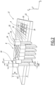
- a representation assembly 10 comprises a representation system 12, at least one pointing and control device 14, for example at least two detection terminals 16 of the position and orientation of the pointing and control device 14, at least a projection device 18 and a controller 20.
- the representation system 12 is configured to represent a geographical area 21 including a relief.
- the geographical area is for example a geographical map.
- the geographical area includes urban elements such as buildings.
- geometric area comprising a relief is meant in particular a geographical area having three dimensions.
- the representation system 12 comprises a support 22 and a plurality of movable elements 24, which are movable in translation relative to the support 22 in an elevation direction Z.
- the direction of elevation Z extends perpendicular to a first direction, called transverse direction longitudinal direction Y in the following.
- transverse direction X and the longitudinal direction Y are oriented horizontally
- elevation direction Z is oriented vertically.
- each movable element 24 is movable in vertical translation relative to the support 22.
- the representation system 12 comprises a table formed by the support 22 and feet, not shown, supporting the support 22.
- the support 22 comprises for example a frame 26, an example of which is illustrated on the figure 2 , and a grid 28, an example of which is illustrated on the figures 5 And 6 .
- the frame 26 and the grid 28 are in particular configured to support each movable element 24.
- the frame 26 preferably extends in the transverse direction X and the longitudinal direction Y.
- the grid 28 extends in a perpendicular plane in the direction of elevation Z.
- the grid 28 comprises for example beams 29 extending parallel to the frame 26, in particular in the transverse direction X and the longitudinal direction Y, so as to form a grid having beams arranged perpendicularly one in relation to the other.
- each beam 29 has an identical distance relative to the neighboring beam, so as to form a grid having openings of identical size relative to each other in the direction of elevation Z.
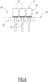
- Each mobile element 24 forms in particular a “voxel”.
- each mobile element 24 comprises a head 30 having at least one display face 31, forming part of the relief of the geographical zone 21.
- Each mobile element 24 for example further comprises a rod 32 extending from the head 30, preferably in a direction opposite to the direction of elevation Z.
- each rod 32 passes through the grid 28.
- each movable element 24 has a height VZ substantially equal to 200 mm, the head 30 of which has a height VE substantially equal to 30 mm.
- each head 30 has the same size.
- each head has the display face 31 forming a part of the relief extending in a plane perpendicular to the direction of elevation Z. This display face 31 has for example a length VY and a width VX substantially equal at 5mm.
- each rod 32 has, in a plane perpendicular to the direction of elevation Z, a length VYB and a width VXB substantially equal to 3.5 mm.
- Each movable element 24 is preferably movable between a rest position, in which each movable element 24 is positioned at the same height predetermined relative to the support 22 in the direction of elevation Z, and a plurality of projection positions distinct from the rest position. For example, in the rest position, the mobile elements 24 adhere to the support 22.
- the mobile elements 24 located in a zone A are in the rest position and the mobile elements 24 positioned in a zone B are in the protruding position.
- each movable element 24 is in contact by friction with at least one neighboring movable element 24.
- each movable element 24 is in contact via at least one lateral face of the head 30 with the neighboring movable element 24.
- a friction force between two neighboring mobile elements 24 is greater than a gravitational force of said mobile elements 24. This makes it possible to maintain the or each mobile element 24 in the protruding position.
- each mobile element 24 is manufactured by additive manufacturing.
- the support 22 is manufactured by additive manufacturing.
- the frame 26 and the grid 28 are manufactured by additive manufacturing, preferably in a single piece.
- each movable element 24 and/or the support 22 is made of a plastic material, in particular a rigid and matte plastic material.
- each movable element 24 is made of the same material as the support 22.
- the representation system 12 for example further comprises an electromagnetic mechanism 34 configured to force all of the mobile elements 24 into the rest position.
- the electromagnetic mechanism 34 is in particular configured to force all of the mobile elements 24 into the rest position simultaneously.
- the electromagnetic mechanism 34 comprises for example a metal net 36, for example a copper winding net.
- the electromagnetic mechanism 34 comprises for example for each movable element 24 a magnetic base 38 fixed to the head 30 of the corresponding movable element 24, in particular fixed on a face of the head 30 facing the metal net 36.
- the metal net 36 receives a predetermined current, it behaves like an electromagnet and attracts each magnetic base 38 of the mobile elements 24 and thus brings the mobile elements 24 into the rest position.
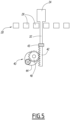
- the representation system 12 further comprises at least one actuator 40 configured to successively move different movable elements 24 of the plurality of movable elements in the direction of elevation Z.
- the actuator 40 is configured to move one of the mobile elements 24, then another, respectively in the direction of elevation Z.
- the actuator 40 is configured to receive a movement command to move the mobile element 24 concerned in the elevation direction Z, as a function of three-dimensional relief data, in particular received from the controller 20 by a data link.
- the actuator 40 comprises a rack 42 configured to come into contact, optionally via a damping device 43, with the rod 32 of the movable element 24 concerned.
- the damping device 43 consists in particular of a material having a lower hardness than a hardness of the material of each movable element 24 and/or of the material of the rack 42.
- the actuator 40 comprises for example an actuator motor 44 comprising a toothed wheel 46.
- the actuator motor 44 is for example an electric motor.
- the rack 42 moves in translation, illustrated in particular on the Figure 4 by an arrow F1.
- the rack 42 moves, by contact with the rod 32, the movable element 24 in the direction of elevation Z.
- the actuator 40 is formed by a pneumatic system configured to successively move the different movable elements 24 of the plurality of movable elements in the direction of elevation Z.
- the representation system 12 further comprises a positioning device 48 configured to position the actuator 40 relative to the movable elements 24 in a positioning plane perpendicular to the elevation direction Z.
- the positioning plane is in particular defined according to the transverse direction X and the longitudinal direction Y.
- the positioning device 48 is configured to receive a positioning command to position the actuator 40 in the positioning plane, in particular as a function of three-dimensional relief data, in particular received by a data link adapted from the controller 20.
- the positioning device 48 comprises for example an arm 50, a first motor 52, and a first toothed belt 54, in particular arranged along the arm 50.
- the arm 50 carries in particular the actuator 40, in particular via the first toothed belt 54.
- the first motor 52 is configured to move the actuator 40 in the transverse direction X in the positioning plane, in particular via the first toothed belt 54. This movement of the first toothed belt 54 is for example illustrated on the Figure 3 by an arrow F2.
- the positioning device 48 further comprises a second motor 56 configured to move the arm 50 carrying the actuator 40 in the longitudinal direction Y in the positioning plane, in particular perpendicular to the transverse direction X.
- the positioning device 48 for example a second toothed belt 58 extending in the longitudinal direction Y.
- the second motor 56 is configured to move the arm 50 via the second toothed belt 58.
- This movement of the second toothed belt 58 is for example illustrated on the Figure 3 by an arrow F3.
- the positioning device 48 further comprises a metal bar 60, extending in particular in the longitudinal direction Y.
- the arm 50 is carried on one side by the second toothed belt 58 and from the other side by the metal bar 60.
- the actuator 40 is configured to successively move some of the movable elements 24 among the plurality of movable elements 24 in the direction of elevation Z.
- the actuator 40 is configured to move one of the movable elements 24 to a first position of the actuator 40 in the positioning plane, then, after repositioning of the actuator 40 by the positioning device 48, another of the movable elements 24 at a second position of the actuator 40.
- the actuator 40 is in particular configured to move the movable element 24 to a given position relative to the positioning plane by movement of the rod 32 by the actuator motor 44.
- the positioning device 48 is configured to move the actuator 40 by combination of the movements implemented by the first motor 52 and the second motor 56 in the positioning plane relative to the movable elements 24, in particular by movement of the arm 50 and by moving the actuator 40 on this arm 50.
- the representation system 12 comprises several actuators 40.
- Each actuator 40 is preferably as described above.
- the representation system 12 comprises a number of actuators 40 strictly less than the number of movable elements 24 of the representation system 12.
- the representation system 12 comprises a number N of actuators, where N is a power of 2 number, such as 2, 4, 8, 16, etc.
- the representation system 12 comprises a positioning device 48 respective for each actuator 40.
- Each positioning device 48 is preferably as described above.
- each actuator 40 is configured to respectively move the mobile elements 24 successively from a predefined part of the plurality of mobile elements 24, for example in a predefined zone of the positioning plan.
- the respective positioning device 48 is configured to move the corresponding actuator 40 in the predefined zone.
- each actuator 40 is incapable of moving the mobile elements outside its predefined zone.
- the representation assembly 10 preferably comprises several pointing and control devices 14.
- the or each pointing and control device 14 is movable relative to the representation system 12.
- the or each pointing and control device 14 is configured to point to a three-dimensional position of the relief of the representation system 12.
- the or each pointing and control device 14 is configured to point to a position presenting at least one object 62 , and is configured to interact with this object 62 on the relief of the geographical area 21, for example configured to detail or modify attributes of the object 62, display a specific layer, in particular of the geographical map, on the relief or move object 62.
- the or each pointing and control device 14 is a COTS (Commercial Off The Shelf) component.
- COTS Consumer Off The Shelf
- the or each pointing and control device 14 is configured to emit a non-optical signal, in particular an electromagnetic signal.
- Each detection terminal 16 is configured to measure a position and/or orientation of the pointing and control device 14 relative to the representation system 12.
- Each detection terminal 16 is preferably an electromagnetic terminal configured to receive an electromagnetic signal from the pointing and control device 14 to obtain said measurement.
- the pointing and control device 14 is in particular configured to emit the electromagnetic signal in a frequency band detectable by each detection terminal 16.
- the representation assembly 10 comprises one or more projection devices 18, for example two.
- the or each projection device 18 is also called a video projection device.
- the or each projection device 18 is configured to project, on the relief, a series of images comprising several objects 62.
- the objects 62 to be represented are fixed or mobile relative to the relief.
- the objects 62 are for example modeled in the representation system 12 by a combination of projected digital images (for example rendering of shape, color, texture, rapid animation) and physical relief elements by the mobile elements 24 (for example 3D rendering, slow animation).
- projected digital images for example rendering of shape, color, texture, rapid animation
- physical relief elements by the mobile elements 24 (for example 3D rendering, slow animation).
- the controller 20 comprises for example, not shown, a reception module, a processing module, and an output module.
- the input module, the processing module, and the output module are each produced at least partially in the form of software, or a software brick, for example stored in a memory of the controller 20 and executable by a processor of controller 20.
- the controller 20 comprises for example a database, not shown, in which data relating to the geographical area 21 are stored, for example cartographic data when the area is a geographical map.
- the controller 20 is for example equipped with a man-machine interface 64 comprising for example a screen, a keyboard and/or a mouse.
- the controller 20 is configured to receive data via the man-machine interface 64, in particular cartographic data relating to the geographical map, in particular relating to the relief, and/or relating to the objects 62.
- the controller 20 is thus configured to generate the movement command for the actuator 40 and/or the positioning command for the positioning device 48 from the map data, and configured to issue this or these command(s).
- the man-machine interface 64 is further configured to display the geographic area 21 and/or data relating to the geographic area 21 and the objects 62.
- a method of interaction 100 between the pointing and control device 14 and the representation system 12 will now be described with reference to the Figure 7 including a flowchart of this process.
- the interaction method 100 is at least partially implemented by the controller 20, that is to say is at least partially implemented by computer.
- the interaction method 100 comprises a measurement phase 110, a processing phase 120, and a display phase 130.
- the measurement phase 110 comprises at least one step 140 of measuring a position and an orientation of the pointing and control device 14.
- each detection terminal 16 measures the position and/or orientation of the pointing and control device 14.
- each detection terminal 16 exchanges data wirelessly, preferably by electromagnetic signal, with the pointing and control device 14 to obtain the measurement of the position and/or orientation of this device, for example according to a protocol of predetermined data exchange, such as a protocol implementing a wireless network called “Wireless Gigabit (WiGig)”, for example at a frequency equal to 60 GHz.
- WiGig Wireless Gigabit
- the measurement step 140 is implemented by at least two detection terminals 16, or three or four detection terminals 16.
- an increased number of detection terminals 16 makes it possible to detect the position and orientation of each pointing and control device 14 located around the table, even in the presence of a user or an obstacle between one detection terminals and the corresponding pointing and control device 14.
- Each detection terminal 16 transmits a signal including the measurement to the controller 20.
- the processing phase 120 is preferably implemented by the controller 20.
- the processing phase 120 comprises an acquisition step 142, a reception step 144, a calculation step 150, a determination step 152, an elaboration step 154, a transmission step 155, a first reception step command 156, and a second command reception step 157.
- the controller 20 acquires a translation position of each movable element 24. For example, the controller 20 receives a measurement of the translation position from a sensor not shown.
- the controller 20 obtains each translation position from a non-represented database.
- This database includes in particular the translation position of each mobile element 24 updated as a result of recent movement in the direction of elevation Z of this mobile element 24.
- the controller 20 obtains each translation position from a signal from the actuator motor 44.
- translation position is meant the respective position of each movable element 24 in the direction of elevation Z.
- the controller 20 receives the measurement of the position and orientation of the pointing and control device(s) 14 relative to the representation system 12.
- the controller 20 receives the signal comprising the measurement from the detection terminal(s) 16, via a suitable data link.
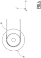
- the controller 20 calculates a virtual line 70 extending from the pointing device and controls 14.
- the controller 20 calculates the virtual line 70 from the position of the pointing and control device 14 according to the measurement received during the reception step 144, and from the orientation of the pointing and control device 14 according to the measurement received during step 144.
- the controller 20 simulates a three-dimensional space, and calculates in this space the virtual line 70 by determining a straight line equation corresponding to a straight line with the position of the measurement and the orientation of the measurement.
- the calculated virtual line 70 is thus oriented from the measured position and according to the measured orientation of the pointing and control device 14.
- Calculation step 150 is an optional step. According to an example, instead of the calculation step 150, the controller 20 accesses a database to obtain a pre-calculated virtual line according to the position and orientation of the pointing device and command 14 received during reception step 144.
- the controller 20 determines, based on the measurement and the translation position of each movable element 24, a three-dimensional position.
- the three-dimensional position forms an intersection of the virtual line 70 with the relief of the geographical zone 21, for example with the head 30, in particular of the display face 31, of one of the mobile elements 24.
- the controller 20 determines the three-dimensional position as a function of the mobile element 24 or mobile elements 24 which are crossed by the virtual line 70.
- the controller 20 simulates the relief in three-dimensional space, and calculates the point of intersection of the virtual line 70 (in particular in the form of a straight line equation) with the simulated relief.
- the controller 20 develops a display signal as a function of the three-dimensional position for displaying at least one image of the geographical area 21 on the relief.
- the image included in the display signal includes a marking of the three-dimensional position as calculated on the relief.
- the image includes the object 62 positioned at the three-dimensional position.
- the image includes several objects 62.
- the development step 154 further comprises an image deformation calculation to obtain the image of the display signal, adapted to the translation position of each mobile element 24.
- the controller 20 implements anamorphosis processing, preferably when the strong relief and the resulting deformation of the video projection justifies it.
- the calculator 20 deforms and/or contracts parts of the image to obtain, on the relief, the display of the image in a non-distorted manner.
- the controller 20 compensates for aberrations due to the projection on the relief, which is non-planar and non-orthogonal to an axis of an objective of the corresponding projection device 18.
- controller 20 implements image enlargements or contractions as a function of the translation positions of each mobile element 24, to obtain the image adapted to the translation position of each mobile element 24.
- the controller 20 transmits the display signal to or to each projection device 18 for displaying the image included in the display signal on the relief.
- the first command reception step 156 and/or the second command reception step 157 comprises modifications or interactions with the object 62 which is pointed by the pointing and control device 14. This pointed object 62 is positioned at the three-dimensional position.
- the controller 20 receives, from the pointing and control device 14, a command for interaction with the object 62 positioned at the three-dimensional position, for example following a press on a corresponding button on the pointing device and command 14 to send the interaction command to the controller 20.
- the interaction command is for example at least one element of the list consisting of a modification of an attribute of the object 62 positioned at the three-dimensional position, a display of information from the object 62 positioned at the three-dimensional position , a marking of the object 62 at the three-dimensional position, and a movement of the object 62 on the relief.
- the interaction command includes the movement of the object 62 on the relief
- the user uses the pointing device and command 14 to move the object on the relief from the three-dimensional position to another position. This is illustrated on the figure 1 by an arrow 65.
- the interaction command includes a modification of data in the object 62, for example an attribute of the object is modified.
- an attribute of the object is modified.
- the object is a vehicle
- a movement or communication capacity of the vehicle is modified by the interaction command.
- the controller 20 incorporates such a modification into the display signal, for the display of the modified data of the object 62.
- the controller 20 incorporates for example in the display signal the marking of the object 62, for example a change in the color of the object 62, for displaying the object in this color.
- the controller 20 receives a command to display a predetermined layer of the relief, in particular from the pointing and command device 14.
- this step comprises the reception by the controller 20 of a command for marking the three-dimensional position, in particular from the pointing and control device 14, for example as a result of entering the corresponding button on the pointing and control device 14.
- the marking command includes marking in the form of a circle 66 around the three-dimensional position, in particular around the object 62.
- the controller 20 incorporates into the display signal the marking corresponding to the marking command for the display of this marking on the relief.
- the interaction method 100 further comprises a programming step 158 of the geographical zone 21.
- the controller 21 receives, in particular via the man-machine interface 64, data relating to the geographical area 21, such as cartographic data relating to the geographical map.
- the controller 20 develops the movement command for the actuator 40 and/or the positioning command for the positioning device 48 from data relating to the geographical area 21, and issues this or these command(s) when programming step 158, to obtain the relief according to the data received, forming the geographical area 21 in three dimensions.
- the positioning device 48 implements the movement corresponding to the positioning command by positioning the actuator 40 below the corresponding movable element 24.
- the actuator 40 implements the movement corresponding to the movement command by moving the corresponding movable element 24 in translation.
- the programming step 158 is implemented at least once before the implementation of the measurement step 140 or the acquisition step 142.
- the display phase 130 comprises a display step 160 by the or each projection device 18 of the image included in the display signal.
- the display step 160 is implemented by at least two projection devices 18. This makes it possible to obtain the display of the image on all the mobile elements 24, and in particular to avoid overlapping. of one of the display faces 31 of the corresponding movable element 24 by another movable element 24 in the protruding position, which is for example arranged between the projection device 18 and the corresponding display face 31.
- the interaction method 100 is preferably implemented several times.
- the measurement phase 110, the processing phase 120, and the display phase 130 are implemented successively one after the other.
- each phase 110, 120,130 is implemented several times.
- At least the acquisition 142, reception 144, determination 152, and elaboration 154 steps are implemented at least once following an implementation of the programming step 158.
- the measurement phase 110, the processing phase 120, and the display phase 130 are implemented simultaneously or in parallel.
- Measuring phase 110 is optional.
- the controller 20 receives the measurement of the position and the orientation in the form of a simulated measurement, for example from a database.
- the calculation step 150, the transmission step 155, the first command reception step 156, the second command reception step 157 and/or the display step 160 is/are one or more steps ( s) optional(s).
- the method 100 is implemented by several control devices 14.
- the interaction method 100 comprises receiving the command to move the mobile elements 24 from the pointing device and command 14 instead of input by the man-machine interface 64.
- the pointing and control device 14 sends a suitable command to the controller 20, and the controller 20 calculates a corresponding signal for the corresponding actuator 40 and/or for the projection device 18.
- the interaction method 100 is particularly simple to implement for a user, while making it possible to obtain an effective three-dimensional perception of the geographical area 21.
- the pointed position namely the three-dimensional position
- the signal displayed contains the name of the object 62 and its attributes.
- the position pointed by the pointing and control device 14 is adapted.
Applications Claiming Priority (1)
| Application Number | Priority Date | Filing Date | Title |
|---|---|---|---|
| FR2210857A FR3141263A1 (fr) | 2022-10-20 | 2022-10-20 | Système de représentation d'une zone géographique comprenant un relief et ensemble comprenant un tel système de représentation |
Publications (1)
| Publication Number | Publication Date |
|---|---|
| EP4358069A1 true EP4358069A1 (de) | 2024-04-24 |
Family
ID=85461738
Family Applications (1)
| Application Number | Title | Priority Date | Filing Date |
|---|---|---|---|
| EP23204569.0A Pending EP4358069A1 (de) | 2022-10-20 | 2023-10-19 | System zur darstellung eines geographischen bereichs mit einem relief und anordnung mit solch einem anzeigesystem |
Country Status (2)
| Country | Link |
|---|---|
| EP (1) | EP4358069A1 (de) |
| FR (1) | FR3141263A1 (de) |
Citations (9)
| Publication number | Priority date | Publication date | Assignee | Title |
|---|---|---|---|---|
| US6145424A (en) * | 1995-11-20 | 2000-11-14 | Amada Company, Limited | Punching machine and method thereof |
| US6257575B1 (en) * | 1999-04-23 | 2001-07-10 | Herbert A. Ortega | Vertically adjustable squares on a game board assembly |
| KR20130071100A (ko) * | 2011-12-20 | 2013-06-28 | 허상훈 | 3차원 모형에 영상을 투사하는 장치 및 방법 |
| US20130217496A1 (en) * | 2012-02-20 | 2013-08-22 | Jake Waldron Olkin | Dynamic Game System And Associated Methods |
| US20150193964A1 (en) * | 2014-01-07 | 2015-07-09 | Electronics And Telecommunications Research Institute | Real-time dynamic non-planar projection apparatus and method |
| EP3048791A2 (de) * | 2015-01-26 | 2016-07-27 | Thales-Raytheon Systems Company SAS | Anzeigeverfahren mindestens eines fensters einer 3d-szene, entsprechendes computerprogrammprodukt und entsprechendes anzeigesystem |
| CH712678A2 (fr) * | 2016-07-05 | 2018-01-15 | Spitz & Tal Sa | Procédé d'affichage de données cartographiques. |
| WO2020249639A1 (fr) * | 2019-06-13 | 2020-12-17 | Airbus Defence And Space Sas | Système numérique de préparation de mission |
| US20210394043A1 (en) * | 2020-06-22 | 2021-12-23 | Zerep Holdings, LLC | Dynamic gameboard |
-
2022
- 2022-10-20 FR FR2210857A patent/FR3141263A1/fr active Pending
-
2023
- 2023-10-19 EP EP23204569.0A patent/EP4358069A1/de active Pending
Patent Citations (9)
| Publication number | Priority date | Publication date | Assignee | Title |
|---|---|---|---|---|
| US6145424A (en) * | 1995-11-20 | 2000-11-14 | Amada Company, Limited | Punching machine and method thereof |
| US6257575B1 (en) * | 1999-04-23 | 2001-07-10 | Herbert A. Ortega | Vertically adjustable squares on a game board assembly |
| KR20130071100A (ko) * | 2011-12-20 | 2013-06-28 | 허상훈 | 3차원 모형에 영상을 투사하는 장치 및 방법 |
| US20130217496A1 (en) * | 2012-02-20 | 2013-08-22 | Jake Waldron Olkin | Dynamic Game System And Associated Methods |
| US20150193964A1 (en) * | 2014-01-07 | 2015-07-09 | Electronics And Telecommunications Research Institute | Real-time dynamic non-planar projection apparatus and method |
| EP3048791A2 (de) * | 2015-01-26 | 2016-07-27 | Thales-Raytheon Systems Company SAS | Anzeigeverfahren mindestens eines fensters einer 3d-szene, entsprechendes computerprogrammprodukt und entsprechendes anzeigesystem |
| CH712678A2 (fr) * | 2016-07-05 | 2018-01-15 | Spitz & Tal Sa | Procédé d'affichage de données cartographiques. |
| WO2020249639A1 (fr) * | 2019-06-13 | 2020-12-17 | Airbus Defence And Space Sas | Système numérique de préparation de mission |
| US20210394043A1 (en) * | 2020-06-22 | 2021-12-23 | Zerep Holdings, LLC | Dynamic gameboard |
Also Published As
| Publication number | Publication date |
|---|---|
| FR3141263A1 (fr) | 2024-04-26 |
Similar Documents
| Publication | Publication Date | Title |
|---|---|---|
| US9646522B2 (en) | Enhanced information delivery using a transparent display | |
| CN105574921B (zh) | 根据图像的自动化纹理映射和动画绘制 | |
| CN107636534A (zh) | 一般球面捕获方法 | |
| FR3041804A1 (fr) | Systeme de simulation tridimensionnelle virtuelle propre a engendrer un environnement virtuel reunissant une pluralite d'utilisateurs et procede associe | |
| US11663689B2 (en) | Foveated rendering using eye motion | |
| CN104520785A (zh) | 基于检测到的输入来更改在显示区域的一部分中提供的内容的属性 | |
| FR2999725A1 (fr) | Procede de reglage d'un secteur de cision/masquage d'un dispositif de scrutation d'environnement, dispositif de reglage et terminal d'operateur correspondants | |
| CN108628436A (zh) | 电子装置、显示方法以及非暂态计算机可读取储存媒体 | |
| EP4358069A1 (de) | System zur darstellung eines geographischen bereichs mit einem relief und anordnung mit solch einem anzeigesystem | |
| EP3983870B1 (de) | Digitales missionsvorbereitungssystem | |
| EP4357888A1 (de) | Verfahren zur interaktion einer zeigevorrichtung und steuerung mit einem dreidimensionalen darstellungssystem und abbildungsanordnung dafür | |
| CN116672706B (zh) | 光照渲染方法、装置、终端和存储介质 | |
| CN108170498B (zh) | 页面内容展示方法及装置 | |
| FR2951564A1 (fr) | Procede et installation d'analyse de parametres geometriques d'un objet | |
| FR3023626A3 (fr) | Dispositif de navigation en realite virtuelle comportant une interface haptique | |
| EP2994813B1 (de) | Verfahren zur steuerung einer grafischen schnittstelle zur anzeige von bildern eines dreidimensionalen objekts | |
| CA2696322C (fr) | Procede de simplification de l'affichage d'elements stationnaires d'une base de donnees embarquee | |
| FR3069936B1 (fr) | Interaction tactile avec des ihm dans un environnement immersif | |
| EP3724749B1 (de) | Gerät für augmented reality anwendung | |
| FR3048521A1 (fr) | Dispositif d'interface homme machine avec des applications graphiques en trois dimensions | |
| EP1124212B1 (de) | 3D-visuelle Präsentationsmethode und Apparat für Autosimulator | |
| FR3071635A1 (fr) | Procede creant une interface projetee tangible pour la selection, la visualisation 3d et la commande des plats du menu directement depuis la table du restaurant, ainsi qu'un dispositif pour la mise en oeuvre du procede. | |
| WO2012104290A1 (fr) | Procédé et dispositif de traitement de séquences d'images d'une scène et système de surveillance d'une scène comportant un tel dispositif | |
| EP1344186A2 (de) | Verfahren und vorrichtung zur darstellung dreidimensionaler szenen in virtueller realität | |
| CH712678B1 (fr) | Procédé d'affichage de données cartographiques. |
Legal Events
| Date | Code | Title | Description |
|---|---|---|---|
| PUAI | Public reference made under article 153(3) epc to a published international application that has entered the european phase |
Free format text: ORIGINAL CODE: 0009012 |
|
| STAA | Information on the status of an ep patent application or granted ep patent |
Free format text: STATUS: THE APPLICATION HAS BEEN PUBLISHED |
|
| AK | Designated contracting states |
Kind code of ref document: A1 Designated state(s): AL AT BE BG CH CY CZ DE DK EE ES FI FR GB GR HR HU IE IS IT LI LT LU LV MC ME MK MT NL NO PL PT RO RS SE SI SK SM TR |