EP4357888A1 - Method for interacting a pointing device and control with a three-dimensional representation system, and representation assembly therefor - Google Patents
Method for interacting a pointing device and control with a three-dimensional representation system, and representation assembly therefor Download PDFInfo
- Publication number
- EP4357888A1 EP4357888A1 EP23204659.9A EP23204659A EP4357888A1 EP 4357888 A1 EP4357888 A1 EP 4357888A1 EP 23204659 A EP23204659 A EP 23204659A EP 4357888 A1 EP4357888 A1 EP 4357888A1
- Authority
- EP
- European Patent Office
- Prior art keywords
- pointing
- relief
- control device
- measurement
- translation
- Prior art date
- Legal status (The legal status is an assumption and is not a legal conclusion. Google has not performed a legal analysis and makes no representation as to the accuracy of the status listed.)
- Pending
Links
- 238000000034 method Methods 0.000 title claims abstract description 36
- 230000003993 interaction Effects 0.000 claims abstract description 54
- 238000013519 translation Methods 0.000 claims abstract description 41
- 238000005259 measurement Methods 0.000 claims abstract description 38
- 238000001514 detection method Methods 0.000 claims description 16
- 238000012545 processing Methods 0.000 claims description 10
- 230000004048 modification Effects 0.000 claims description 8
- 238000012986 modification Methods 0.000 claims description 8
- 238000011161 development Methods 0.000 claims description 7
- 230000006870 function Effects 0.000 description 9
- 239000000463 material Substances 0.000 description 6
- 239000011521 glass Substances 0.000 description 5
- 230000007246 mechanism Effects 0.000 description 5
- 239000002184 metal Substances 0.000 description 5
- 229910052751 metal Inorganic materials 0.000 description 5
- 230000008447 perception Effects 0.000 description 4
- 239000000654 additive Substances 0.000 description 3
- 230000000996 additive effect Effects 0.000 description 3
- 230000005540 biological transmission Effects 0.000 description 3
- 238000004519 manufacturing process Methods 0.000 description 3
- 230000008569 process Effects 0.000 description 3
- 230000008602 contraction Effects 0.000 description 2
- 238000013016 damping Methods 0.000 description 2
- 238000009877 rendering Methods 0.000 description 2
- RYGMFSIKBFXOCR-UHFFFAOYSA-N Copper Chemical compound [Cu] RYGMFSIKBFXOCR-UHFFFAOYSA-N 0.000 description 1
- 230000004075 alteration Effects 0.000 description 1
- 208000003464 asthenopia Diseases 0.000 description 1
- 230000003190 augmentative effect Effects 0.000 description 1
- 230000008859 change Effects 0.000 description 1
- 238000004891 communication Methods 0.000 description 1
- 229910052802 copper Inorganic materials 0.000 description 1
- 239000010949 copper Substances 0.000 description 1
- 238000002955 isolation Methods 0.000 description 1
- 230000003287 optical effect Effects 0.000 description 1
- 238000004804 winding Methods 0.000 description 1
Images


Classifications
-
- G—PHYSICS
- G06—COMPUTING; CALCULATING OR COUNTING
- G06F—ELECTRIC DIGITAL DATA PROCESSING
- G06F3/00—Input arrangements for transferring data to be processed into a form capable of being handled by the computer; Output arrangements for transferring data from processing unit to output unit, e.g. interface arrangements
- G06F3/01—Input arrangements or combined input and output arrangements for interaction between user and computer
- G06F3/011—Arrangements for interaction with the human body, e.g. for user immersion in virtual reality
-
- G—PHYSICS
- G06—COMPUTING; CALCULATING OR COUNTING
- G06F—ELECTRIC DIGITAL DATA PROCESSING
- G06F3/00—Input arrangements for transferring data to be processed into a form capable of being handled by the computer; Output arrangements for transferring data from processing unit to output unit, e.g. interface arrangements
- G06F3/01—Input arrangements or combined input and output arrangements for interaction between user and computer
- G06F3/016—Input arrangements with force or tactile feedback as computer generated output to the user
-
- G—PHYSICS
- G06—COMPUTING; CALCULATING OR COUNTING
- G06F—ELECTRIC DIGITAL DATA PROCESSING
- G06F3/00—Input arrangements for transferring data to be processed into a form capable of being handled by the computer; Output arrangements for transferring data from processing unit to output unit, e.g. interface arrangements
- G06F3/01—Input arrangements or combined input and output arrangements for interaction between user and computer
- G06F3/03—Arrangements for converting the position or the displacement of a member into a coded form
- G06F3/033—Pointing devices displaced or positioned by the user, e.g. mice, trackballs, pens or joysticks; Accessories therefor
- G06F3/0346—Pointing devices displaced or positioned by the user, e.g. mice, trackballs, pens or joysticks; Accessories therefor with detection of the device orientation or free movement in a 3D space, e.g. 3D mice, 6-DOF [six degrees of freedom] pointers using gyroscopes, accelerometers or tilt-sensors
Definitions
- the present invention relates to a method of interaction between at least one pointing and control device and a system for representing a geographical area comprising a relief.
- the invention further relates to a representation assembly comprising at least one pointing and control device and a system for representing a geographical area comprising a relief.
- touch screens For example, for collaborative work, such screens can be arranged in the form of a table. A plurality of users located around the table are able to interact with elements displayed on the touch screen.
- touch screens generally only allow a two-dimensional display. Consequently, a three-dimensional perception of, for example, a map, a terrain elevation model or a geographic location is not obtained by such screens.
- 3D glasses for example active or passive anaglyph type glasses, immersive augmented reality headsets. or virtual allowing the perception of the third dimension to be reproduced.
- 3D glasses for example active or passive anaglyph type glasses, immersive augmented reality headsets. or virtual allowing the perception of the third dimension to be reproduced.
- users located around the table then use 3D glasses to obtain a three-dimensional view.
- using such 3D glasses is not always easy for users.
- it is not always easy to implement collaborative work using the card in the presence of 3D glasses on the other hand users often experience visual fatigue when wearing them.
- An aim of the invention is thus to at least reduce the aforementioned drawbacks.
- an aim of the invention is to obtain a method of interaction with a system for representing a geographical area, which is particularly simple to implement for a user, while making it possible to obtain a three-dimensional perception. geographical area.
- the interaction process makes it possible to interact in a particularly simple manner with the representation system.
- a position pointed by the pointing and controlling device on the terrain namely the precise three-dimensional position, is determined, and the display signal is determined according to this position.
- the three-dimensional position is in particular defined by three coordinates on the relief, in an elevation direction, a transverse direction and a longitudinal direction perpendicular to each other.
- the interaction method makes it possible to interact with the representation system via the pointing and control device.
- Using the pointing and control device allows rapid and efficient interaction with the representation system, for example by pointing to positions and/or objects from a position of a user remotely or adjacent to the system of representation.
- a representation assembly 10 comprises a representation system 12, at least one pointing and control device 14, for example at least two detection terminals 16 of the position and orientation of the pointing and control device 14, at least a projection device 18 and a controller 20.
- the representation system 12 is configured to represent a geographical area 21 including a relief.
- the geographical area is for example a geographical map.
- the geographical area includes urban elements such as buildings.
- geometric area comprising a relief is meant in particular a geographical area having three dimensions.
- the representation system 12 comprises a support 22 and a plurality of movable elements 24, which are movable in translation relative to the support 22 in an elevation direction Z.
- the elevation direction Z extends perpendicular to a first direction, called transverse direction X in the following, and a second direction, called longitudinal direction Y in the following.
- transverse direction X and the longitudinal direction Y are oriented horizontally
- longitudinal direction Y is oriented vertically.
- each movable element 24 is movable in vertical translation relative to the support 22.
- the representation system 12 comprises a table formed by the support 22 and feet, not shown, supporting the support 22.
- the support 22 comprises for example a frame 26, an example of which is illustrated on the figure 2 , and a grid 28, an example of which is illustrated on the figures 5 And 6 .
- the frame 26 and the grid 28 are in particular configured to support each movable element 24.
- the frame 26 preferably extends in the transverse direction X and the longitudinal direction Y.
- the grid 28 extends in a perpendicular plane in the direction of elevation Z.
- the grid 28 comprises for example beams 29 extending parallel to the frame 26, in particular in the transverse direction X and the longitudinal direction Y, so as to form a grid having beams arranged perpendicularly one in relation to the other.
- each beam 29 has an identical distance relative to the neighboring beam, so as to form a grid having openings of identical size relative to each other in the direction of elevation Z.
- Each mobile element 24 forms in particular a “voxel” (word composed of the word “vo” from “volume” and “xel” from “pixel”, the word “pixel” being a contraction of the English terms “picture” (for image) and “element” (for element)).
- each mobile element 24 comprises a head 30 having at least one display face 31, forming part of the relief of the geographical zone 21.
- Each mobile element 24 for example further comprises a rod 32 extending from the head 30, preferably in a direction opposite to the direction of elevation Z.
- each rod 32 passes through the grid 28.
- each movable element 24 has a height VZ substantially equal to 200 mm, the head 30 of which has a height VE substantially equal to 30 mm.
- each head 30 has the same size.
- each head has the display face 31 forming a part of the relief extending in a plane perpendicular to the direction of elevation Z. This display face 31 has for example a length VY and a width VX substantially equal at 5mm.
- each rod 32 has, in a plane perpendicular to the direction of elevation Z, a length VYB and a width VXB substantially equal to 3.5 mm.
- Each movable element 24 is preferably movable between a rest position, in which each movable element 24 is positioned at the same predetermined height relative to the support 22 in the direction of elevation Z, and a plurality of distinct projection positions of the rest position. For example, in the rest position, the mobile elements 24 adhere to the support 22.
- the mobile elements 24 located in a zone A are in the rest position and the mobile elements 24 positioned in a zone B are in the protruding position.
- each movable element 24 is in contact by friction with at least one neighboring movable element 24.
- each movable element 24 is in contact via at least one lateral face of the head 30 with the neighboring movable element 24.
- a friction force between two neighboring mobile elements 24 is greater than a gravitational force of said mobile elements 24. This makes it possible to maintain the or each mobile element 24 in the protruding position.
- each mobile element 24 is manufactured by additive manufacturing.
- the support 22 is manufactured by additive manufacturing.
- the frame 26 and the grid 28 are manufactured by additive manufacturing, preferably in a single piece.
- each movable element 24 and/or the support 22 is made of a plastic material, in particular a rigid and matte plastic material.
- each movable element 24 is made of the same material as the support 22.
- the representation system 12 for example further comprises an electromagnetic mechanism 34 configured to force all of the mobile elements 24 into the rest position.
- the electromagnetic mechanism 34 is in particular configured to force all of the mobile elements 24 into the rest position simultaneously.
- the electromagnetic mechanism 34 comprises for example a metal net 36, for example a copper winding net.
- the electromagnetic mechanism 34 comprises for example for each movable element 24 a magnetic base 38 fixed to the head 30 of the corresponding movable element 24, in particular fixed on a face of the head 30 facing the metal net 36.
- the metal net 36 receives a predetermined current, it behaves like an electromagnet and attracts each magnetic base 38 of the mobile elements 24 and thus brings the mobile elements 24 into the rest position.
- the representation system 12 further comprises at least one actuator 40 configured to successively move different movable elements 24 of the plurality of movable elements in the direction of elevation Z.
- the actuator 40 is configured to move the one of the movable elements 24, then another, respectively in the direction of elevation Z.
- the actuator 40 is configured to receive a movement command to move the mobile element 24 concerned in the elevation direction Z, as a function of three-dimensional relief data, in particular received from the controller 20 by a data link.
- the actuator 40 comprises a rack 42 configured to come into contact, optionally via a damping device 43, with the rod 32 of the movable element 24 concerned.
- the damping device 43 consists in particular of a material having a lower hardness than a hardness of the material of each movable element 24 and/or of the material of the rack 42.
- the actuator 40 comprises for example an actuator motor 44 comprising a toothed wheel 46.
- the actuator motor 44 is for example an electric motor.
- the rack 42 moves in translation, illustrated in particular on the Figure 4 by an arrow F1.
- the rack 42 moves, by contact with the rod 32, the movable element 24 in the direction of elevation Z.
- the actuator 40 is formed by a pneumatic system configured to successively move the different movable elements 24 of the plurality of movable elements in the direction of elevation Z.
- the representation system 12 further comprises a positioning device 48 configured to position the actuator 40 relative to the movable elements 24 in a positioning plane perpendicular to the elevation direction Z.
- the positioning plane is in particular defined according to the transverse direction X and the longitudinal direction Y.
- the positioning device 48 is configured to receive a positioning command to position the actuator 40 in the positioning plane, in particular as a function of three-dimensional relief data, in particular received by a data link adapted from the controller 20.
- the positioning device 48 comprises for example an arm 50, a first motor 52, and a first toothed belt 54, in particular arranged along the arm 50.
- the arm 50 carries in particular the actuator 40, in particular via the first toothed belt 54.
- the first motor 52 is configured to move the actuator 40 in the transverse direction X in the positioning plane, in particular via the first toothed belt 54. This movement of the first toothed belt 54 is for example illustrated on the Figure 3 by an arrow F2.
- the positioning device 48 further comprises a second motor 56 configured to move the arm 50 carrying the actuator 40 in the longitudinal direction Y in the positioning plane, in particular perpendicular to the transverse direction X.
- the positioning device 48 for example a second toothed belt 58 extending in the longitudinal direction Y.
- the second motor 56 is configured to move the arm 50 via the second toothed belt 58.
- This movement of the second toothed belt 58 is for example illustrated on the Figure 3 by an arrow F3.
- the positioning device 48 further comprises a metal bar 60, extending in particular in the longitudinal direction Y.
- the arm 50 is carried on one side by the second toothed belt 58 and from the other side by the metal bar 60.
- the actuator 40 is configured to successively move some of the movable elements 24 among the plurality of movable elements 24 in the direction of elevation Z.
- the actuator 40 is configured to move one of the movable elements 24 to a first position of the actuator 40 in the positioning plane, then, after repositioning of the actuator 40 by the positioning device 48, another of the movable elements 24 at a second position of the actuator 40.
- the actuator 40 is in particular configured to move the movable element 24 to a given position relative to the positioning plane by movement of the rod 32 by the actuator motor 44.
- the positioning device 48 is configured to move the actuator 40 by combination of the movements implemented by the first motor 52 and the second motor 56 in the positioning plane relative to the movable elements 24, in particular by movement of the arm 50 and by movement of the actuator 40 on this arm 50.
- the representation system 12 comprises several actuators 40.
- Each actuator 40 is preferably as described above.
- the representation system 12 comprises a number of actuators 40 strictly less than the number of movable elements 24 of the representation system 12.
- the representation system 12 comprises a number N of actuators, where N is a power of 2 number, such as 2, 4, 8, 16, etc.
- the representation system 12 comprises a respective positioning device 48 for each actuator 40.
- Each positioning device 48 is preferably as described above.
- each actuator 40 is configured to respectively move the mobile elements 24 successively from a predefined part of the plurality of mobile elements 24, for example in a predefined zone of the positioning plan.
- the respective positioning device 48 is configured to move the corresponding actuator 40 in the predefined zone.
- each actuator 40 is incapable of moving the mobile elements outside its predefined zone.
- the representation assembly 10 preferably comprises several pointing and control devices 14.
- the or each pointing and control device 14 is movable relative to the representation system 12.
- the or each pointing and control device 14 is configured to point to a three-dimensional position of the relief of the representation system 12.
- the or each pointing and control device 14 is configured to point to a position presenting at least one object 62 , and is configured to interact with this object 62 on the relief of the geographical area 21, for example configured to detail or modify attributes of the object 62, display a specific layer, in particular of the geographical map, on the relief or move object 62.
- the or each pointing and control device 14 is a COTS (Commercial Off The Shelf) component.
- COTS Consumer Off The Shelf
- the or each pointing and control device 14 is configured to emit a non-optical signal, in particular an electromagnetic signal.
- Each detection terminal 16 is configured to measure a position and/or orientation of the pointing and control device 14 relative to the representation system 12.
- Each detection terminal 16 is preferably an electromagnetic terminal configured to receive an electromagnetic signal from the pointing and control device 14 to obtain said measurement.
- the pointing and control device 14 is in particular configured to emit the electromagnetic signal in a frequency band detectable by each detection terminal 16.
- the representation assembly 10 comprises one or more projection devices 18, for example two.
- the or each projection device 18 is also called a video projection device.
- the or each projection device 18 is configured to project, on the relief, a series of images comprising several objects 62.
- the objects 62 to be represented are fixed or mobile relative to the relief.
- the objects 62 are for example modeled in the representation system 12 by a combination of projected digital images (for example rendering of shape, color, texture, rapid animation) and physical relief elements by the mobile elements 24 (for example 3D rendering, slow animation).
- projected digital images for example rendering of shape, color, texture, rapid animation
- physical relief elements by the mobile elements 24 (for example 3D rendering, slow animation).
- the controller 20 comprises for example, not shown, a reception module, a processing module, and an output module.
- the input module, the processing module, and the output module are each produced at least partially in the form of software, or a software brick, for example stored in a memory of the controller 20 and executable by a processor of controller 20.
- the controller 20 comprises for example a database, not shown, in which data relating to the geographical area 21 are stored, for example cartographic data when the area is a geographical map.
- the controller 20 is for example equipped with a man-machine interface 64 comprising for example a screen, a keyboard and/or a mouse.
- the controller 20 is configured to receive data via the man-machine interface 64, in particular cartographic data relating to the geographical map, in particular relating to the relief, and/or relating to the objects 62.
- the controller 20 is thus configured to generate the movement command for the actuator 40 and/or the positioning command for the positioning device 48 from the map data, and configured to issue this or these command(s).
- the man-machine interface 64 is further configured to display the geographic area 21 and/or data relating to the geographic area 21 and the objects 62.
- a method of interaction 100 between the pointing and control device 14 and the representation system 12 will now be described with reference to the Figure 7 including a flowchart of this process.
- the interaction method 100 is at least partially implemented by the controller 20, that is to say is at least partially implemented by computer.
- the interaction method 100 comprises a measurement phase 110, a processing phase 120, and a display phase 130.
- the measurement phase 110 comprises at least one step 140 of measuring a position and an orientation of the pointing and control device 14.
- each detection terminal 16 measures the position and/or orientation of the pointing and control device 14.
- each detection terminal 16 exchanges data wirelessly, preferably by electromagnetic signal, with the pointing and control device 14 to obtain the measurement of the position and/or orientation of this device, for example according to a protocol of predetermined data exchange, such as a protocol implementing a wireless network called “Wireless Gigabit (WiGig)”, for example at a frequency equal to 60 GHz.
- WiGig Wireless Gigabit
- the measurement step 140 is implemented by at least two detection terminals 16, or three or four detection terminals 16.
- an increased number of detection terminals 16 makes it possible to detect the position and orientation of each pointing and control device 14 located around the table, even in the presence of a user or an obstacle between one detection terminals and the corresponding pointing and control device 14.
- Each detection terminal 16 transmits a signal including the measurement to the controller 20.
- the processing phase 120 is preferably implemented by the controller 20.
- the processing phase 120 comprises an acquisition step 142, a reception step 144, a calculation step 150, a determination step 152, an elaboration step 154, a transmission step 155, a first reception step command 156, and a second command reception step 157.
- the controller 20 acquires a translation position of each movable element 24. For example, the controller 20 receives a measurement of the translation position from a sensor not shown.
- the controller 20 obtains each translation position from a non-represented database.
- This database includes in particular the translation position of each mobile element 24 updated as a result of recent movement in the direction of elevation Z of this mobile element 24.
- the controller 20 obtains each translation position from a signal from the actuator motor 44.
- translation position is meant the respective position of each movable element 24 in the direction of elevation Z.
- the controller 20 receives the measurement of the position and orientation of the pointing and control device(s) 14 relative to the representation system 12.
- the controller 20 receives the signal comprising the measurement from the detection terminal(s) 16, via a suitable data link.
- the controller 20 calculates a virtual line 70 extending from the pointing device and controls 14.
- the controller 20 calculates the virtual line 70 from the position of the pointing and control device 14 according to the measurement received during the reception step 144, and from the orientation of the pointing and control device 14 according to the measurement received during step 144.
- the controller 20 simulates a three-dimensional space, and calculates in this space the virtual line 70 by determining a straight line equation corresponding to a straight line with the position of the measurement and the orientation of the measurement.
- the calculated virtual line 70 is thus oriented from the measured position and according to the measured orientation of the pointing and control device 14.
- Calculation step 150 is an optional step. According to an example, instead of the calculation step 150, the controller 20 accesses a database to obtain a pre-calculated virtual line according to the position and orientation of the pointing device and command 14 received during reception step 144.
- the controller 20 determines, based on the measurement and the translation position of each movable element 24, a three-dimensional position.
- the three-dimensional position forms an intersection of the virtual line 70 with the relief of the geographical zone 21, for example with the head 30, in particular of the display face 31, of one of the mobile elements 24.
- the controller 20 determines the three-dimensional position as a function of the mobile element 24 or mobile elements 24 which are crossed by the virtual line 70.
- the controller 20 simulates the relief in three-dimensional space, and calculates the point of intersection of the virtual line 70 (in particular in the form of a straight line equation) with the simulated relief.
- the controller 20 develops a display signal as a function of the three-dimensional position for displaying at least one image of the geographical area 21 on the relief.
- the image included in the display signal includes a marking of the three-dimensional position as calculated on the relief.
- the image includes the object 62 positioned at the three-dimensional position.
- the image includes several objects 62.
- the development step 154 further comprises an image deformation calculation to obtain the image of the display signal, adapted to the translation position of each mobile element 24.
- the controller 20 implements anamorphosis processing, preferably when the strong relief and the resulting deformation of the video projection justifies it.
- the calculator 20 deforms and/or contracts parts of the image to obtain, on the relief, the display of the image in a non-distorted manner.
- the controller 20 compensates for aberrations due to the projection on the relief, which is non-planar and non-orthogonal to an axis of an objective of the corresponding projection device 18.
- controller 20 implements image enlargements or contractions as a function of the translation positions of each mobile element 24, to obtain the image adapted to the translation position of each mobile element 24.
- the controller 20 transmits the display signal to or to each projection device 18 for displaying the image included in the display signal on the relief.
- the first command reception step 156 and/or the second command reception step 157 comprises modifications or interactions with the object 62 which is pointed by the pointing and control device 14. This pointed object 62 is positioned at the three-dimensional position.
- the controller 20 receives, from the pointing and control device 14, a command for interaction with the object 62 positioned at the three-dimensional position, for example following a press on a corresponding button on the pointing device and command 14 to send the interaction command to the controller 20.
- the interaction command is for example at least one element of the list consisting of a modification of an attribute of the object 62 positioned at the three-dimensional position, a display of information from the object 62 positioned at the three-dimensional position , a marking of the object 62 at the three-dimensional position, and a movement of the object 62 on the relief.
- the interaction command includes moving the object 62 on the relief
- the user uses the pointing and control device 14 to move the object on the relief from the three-dimensional position to another position. This is illustrated on the figure 1 by an arrow 65.
- the interaction command includes a modification of data in the object 62, for example an attribute of the object is modified.
- an attribute of the object is modified.
- the object is a vehicle
- a movement or communication capacity of the vehicle is modified by the interaction command.
- the controller 20 incorporates such a modification into the display signal, for the display of the modified data of the object 62.
- the controller 20 incorporates for example in the display signal the marking of the object 62, for example a change in the color of the object 62, for displaying the object in this color.
- the controller 20 receives a command to display a predetermined layer of the relief, in particular from the pointing and command device 14.
- this step comprises the reception by the controller 20 of a command for marking the three-dimensional position, in particular from the pointing and control device 14, for example as a result of entering the corresponding button on the pointing and control device 14.
- the marking command includes marking in the form of a circle 66 around the three-dimensional position, in particular around the object 62.
- the controller 20 incorporates into the display signal the marking corresponding to the marking command for the display of this marking on the relief.
- the interaction method 100 further comprises a programming step 158 of the geographical zone 21.
- the controller 21 receives, in particular via the man-machine interface 64, data relating to the geographical area 21, such as cartographic data relating to the geographical map.
- the controller 20 develops the movement command for the actuator 40 and/or the positioning command for the positioning device 48 from data relating to the geographical area 21, and issues this or these command(s) when programming step 158, to obtain the relief according to the data received, forming the geographical area 21 in three dimensions.
- the positioning device 48 implements the movement corresponding to the positioning command by positioning the actuator 40 below the corresponding movable element 24.
- the actuator 40 implements the movement corresponding to the movement command by moving the corresponding movable element 24 in translation.
- the programming step 158 is implemented at least once before the implementation of the measurement step 140 or the acquisition step 142.
- the display phase 130 comprises a display step 160 by the or each projection device 18 of the image included in the display signal.
- the display step 160 is implemented by at least two projection devices 18. This makes it possible to obtain the display of the image on all the mobile elements 24, and in particular to avoid overlapping. of one of the display faces 31 of the corresponding movable element 24 by another movable element 24 in the protruding position, which is for example arranged between the projection device 18 and the corresponding display face 31.
- the interaction method 100 is preferably implemented several times.
- the measurement phase 110, the processing phase 120, and the display phase 130 are implemented successively one after the other.
- each phase 110, 120,130 is implemented several times.
- At least the acquisition 142, reception 144, determination 152, and elaboration 154 steps are implemented at least once following an implementation of the programming step 158.
- the measurement phase 110, the processing phase 120, and the display phase 130 are implemented simultaneously or in parallel.
- Measuring phase 110 is optional.
- the controller 20 receives the measurement of the position and the orientation in the form of a simulated measurement, for example from a database.
- the calculation step 150, the transmission step 155, the first command reception step 156, the second command reception step 157 and/or the display step 160 is/are one or more steps ( s) optional(s).
- the method 100 is implemented by several control devices 14.
- the interaction method 100 comprises receiving the command for movement of the mobile elements 24 from the pointing and command device 14 instead of input by the man-machine interface 64.
- the pointing and control device 14 sends a suitable command to the controller 20, and the controller 20 calculates a corresponding signal for the corresponding actuator 40 and/or for the projection device 18.
- the interaction method 100 is particularly simple to implement for a user, while making it possible to obtain an effective three-dimensional perception of the geographical area 21.
- the pointed position namely the three-dimensional position
- the signal displayed contains the name of the object 62 and its attributes.
- the position pointed by the pointing and control device 14 is adapted.
Landscapes
- Engineering & Computer Science (AREA)
- General Engineering & Computer Science (AREA)
- Theoretical Computer Science (AREA)
- Human Computer Interaction (AREA)
- Physics & Mathematics (AREA)
- General Physics & Mathematics (AREA)
- Processing Or Creating Images (AREA)
- User Interface Of Digital Computer (AREA)
- Position Input By Displaying (AREA)
Abstract
Procédé d'interaction entre au moins un dispositif de pointage et commande (14) et un système de représentation (12) d'une zone géographique (21) comprenant un relief, le système de représentation (12) comprenant un support et une pluralité d'éléments mobiles (24) en translation par rapport au support selon une direction d'élévation (Z), chaque élément mobile (24) comprenant une tête présentant au moins une face d'affichage formant une partie dudit relief, le dispositif de pointage et commande (14) étant mobile par rapport au système de représentation (12), le procédé d'interaction comprenant des étapes suivantes :- acquisition d'une position de translation de chaque élément mobile (24),- réception d'une mesure d'une position et d'une orientation du dispositif de pointage et commande (14),- détermination d'une position tridimensionnelle.Method of interaction between at least one pointing and control device (14) and a representation system (12) of a geographical area (21) comprising a relief, the representation system (12) comprising a support and a plurality of movable elements (24) in translation relative to the support in a direction of elevation (Z), each movable element (24) comprising a head having at least one display face forming a part of said relief, the pointing device and control (14) being mobile relative to the representation system (12), the interaction method comprising the following steps: - acquisition of a translation position of each movable element (24), - reception of a measurement of a position and orientation of the pointing and control device (14), - determination of a three-dimensional position.
Description
La présente invention concerne un procédé d'interaction entre au moins un dispositif de pointage et commande et un système de représentation d'une zone géographique comprenant un relief.The present invention relates to a method of interaction between at least one pointing and control device and a system for representing a geographical area comprising a relief.
L'invention concerne en outre un ensemble de représentation comprenant au moins un dispositif de pointage et commande et un système de représentation d'une zone géographique comprenant un relief.The invention further relates to a representation assembly comprising at least one pointing and control device and a system for representing a geographical area comprising a relief.
Pour interagir avec des systèmes permettant un affichage d'un flux d'images, comprenant par exemple une carte géographique, il est connu d'implémenter des écrans tactiles. Par exemple, pour un travail collaboratif, de tels écrans peuvent être agencés sous forme d'une table. Une pluralité d'utilisateurs situés autour de la table sont aptes à interagir avec des éléments affichés sur l'écran tactile.To interact with systems allowing a display of a stream of images, comprising for example a geographical map, it is known to implement touch screens. For example, for collaborative work, such screens can be arranged in the form of a table. A plurality of users located around the table are able to interact with elements displayed on the touch screen.
Toutefois, de tels écrans tactiles permettent de manière générale uniquement un affichage en deux dimensions. Par conséquent, une perception tridimensionnelle par exemple d'une carte, d'un modèle d'élévation de terrain ou d'une situation géographique n'est pas obtenue par de tels écrans.However, such touch screens generally only allow a two-dimensional display. Consequently, a three-dimensional perception of, for example, a map, a terrain elevation model or a geographic location is not obtained by such screens.
D'autres systèmes d'affichage permettent déjà d'obtenir une vue tridimensionnelle d'une telle carte, par exemple par un affichage spécifique et en utilisant des lunettes 3D, par exemple des lunettes actives ou passives type anaglyphes, des casques immersifs de réalité augmentée ou virtuelle permettant de reproduire la perception de la troisième dimension. Dans l'exemple d'un système de représentation sous forme de table, des utilisateurs situés autour de la table utilisent alors des lunettes 3D pour obtenir une vue tridimensionnelle. Toutefois, l'utilisation de telles lunettes 3D n'est pas toujours aisée pour les utilisateurs. En particulier, d'une part il n'est pas toujours facile de mettre en oeuvre un travail collaboratif en utilisant la carte en présence de lunettes 3D, d'autre part les utilisateurs éprouvent souvent une fatigue visuelle à les porter.Other display systems already make it possible to obtain a three-dimensional view of such a map, for example by a specific display and by using 3D glasses, for example active or passive anaglyph type glasses, immersive augmented reality headsets. or virtual allowing the perception of the third dimension to be reproduced. In the example of a tabletop representation system, users located around the table then use 3D glasses to obtain a three-dimensional view. However, using such 3D glasses is not always easy for users. In particular, on the one hand it is not always easy to implement collaborative work using the card in the presence of 3D glasses, on the other hand users often experience visual fatigue when wearing them.
Un but de l'invention est ainsi d'au moins réduire les inconvénients précités.An aim of the invention is thus to at least reduce the aforementioned drawbacks.
En particulier, un but de l'invention est d'obtenir un procédé d'interaction avec un système de représentation d'une zone géographique, qui est particulièrement simple à mettre en oeuvre pour un utilisateur, tout en permettant d'obtenir une perception tridimensionnelle effective de la zone géographique.In particular, an aim of the invention is to obtain a method of interaction with a system for representing a geographical area, which is particularly simple to implement for a user, while making it possible to obtain a three-dimensional perception. geographical area.
A cet effet, l'invention a pour objet un procédé d'interaction entre au moins un dispositif de pointage et commande et un système de représentation d'une zone géographique comprenant un relief, le système de représentation comprenant un support et une pluralité d'éléments mobiles en translation par rapport au support selon une direction d'élévation, chaque élément mobile comprenant une tête présentant au moins une face d'affichage formant une partie dudit relief, le dispositif de pointage et commande étant mobile par rapport au système de représentation, le procédé d'interaction comprenant des étapes suivantes :
- acquisition d'une position de translation de chaque élément mobile,
- réception d'une mesure d'une position et d'une orientation du dispositif de pointage et commande par rapport au système de représentation,
- détermination, en fonction de ladite mesure et de la position de translation de chaque élément mobile, d'une position tridimensionnelle formant une intersection d'une ligne virtuelle s'étendant à partir du dispositif de pointage et commande avec le relief,
- élaboration d'un signal d'affichage en fonction de la position tridimensionnelle pour un affichage d'au moins une image de la zone géographique sur chaque face d'affichage.
- acquisition of a translation position of each mobile element,
- receiving a measurement of a position and an orientation of the pointing device and controlling it relative to the representation system,
- determination, as a function of said measurement and the translation position of each movable element, of a three-dimensional position forming an intersection of a virtual line extending from the pointing and control device with the relief,
- development of a display signal as a function of the three-dimensional position for displaying at least one image of the geographical area on each display face.
En effet, le procédé d'interaction permet d'interagir de manière particulièrement simple avec le système de représentation. En utilisant le dispositif de pointage et commande, une position pointée par le dispositif de pointage et commande sur le relief, à savoir la position tridimensionnelle précise, est déterminée, et le signal d'affichage est déterminé en fonction de cette position.Indeed, the interaction process makes it possible to interact in a particularly simple manner with the representation system. By using the pointing and controlling device, a position pointed by the pointing and controlling device on the terrain, namely the precise three-dimensional position, is determined, and the display signal is determined according to this position.
La position tridimensionnelle est en particulier définie par trois coordonnées sur le relief, selon une direction d'élévation, une direction transversale et une direction longitudinale perpendiculaires l'une par rapport à l'autre.The three-dimensional position is in particular defined by three coordinates on the relief, in an elevation direction, a transverse direction and a longitudinal direction perpendicular to each other.
Ainsi, le procédé d'interaction permet d'interagir avec le système de représentation par l'intermédiaire du dispositif de pointage et commande.Thus, the interaction method makes it possible to interact with the representation system via the pointing and control device.
Le fait d'utiliser le dispositif de pointage et commande permet une interaction rapide et efficace avec le système de représentation, par exemple en pointant des positions et/ou objets à partir d'une position d'un utilisateur à distance ou à côté du système de représentation.Using the pointing and control device allows rapid and efficient interaction with the representation system, for example by pointing to positions and/or objects from a position of a user remotely or adjacent to the system of representation.
Suivant d'autres aspects avantageux de l'invention, le procédé d'interaction comprend une ou plusieurs des caractéristiques suivantes, prise(s) isolément ou suivant toutes les combinaisons techniquement possibles :
- l'étape d'élaboration du signal d'affichage comprend un calcul de déformation d'image pour obtenir ladite image, adaptée à la position de translation de chaque élément mobile, le calcul de déformation d'image comprenant de préférence un traitement par anamorphose ;
- le procédé d'interaction comprend en outre une étape de calcul de la ligne virtuelle, orientée à partir de la position de ladite mesure et selon l'orientation de ladite mesure du dispositif de pointage et commande ;
- l'au moins une image comprend au moins un objet positionné à la position tridimensionnelle sur le relief ;
- le procédé d'interaction comprend en outre une première étape de réception de commande comprenant la réception, de la part du dispositif de pointage et commande, d'une commande d'interaction avec ledit objet à la position tridimensionnelle ;
- la commande d'interaction est au moins un élément de la liste consistant en une modification d'un attribut de l'objet positionné à la position tridimensionnelle, un affichage d'une information de l'objet positionné à la position tridimensionnelle, un marquage de l'objet à la position tridimensionnelle et un déplacement de l'objet sur le relief ;
- le procédé d'interaction comprend en outre une seconde étape de réception de commande comprenant la réception d'une commande d'affichage d'une couche prédéterminée du relief et/ou une commande de marquage de la position tridimensionnelle ;
- le procédé d'interaction comprend en outre une étape de mesure par au moins deux bornes de détection fixes par rapport au système de représentation, de la position et de l'orientation du dispositif de pointage et commande pour obtenir ladite mesure de la position et/ou de l'orientation du dispositif de pointage et commande ;
- les bornes de détection sont des bornes électromagnétiques recevant un signal électromagnétique du dispositif de pointage et commande pour obtenir ladite mesure ;
- le procédé d'interaction comprend en outre une étape d'émission du signal d'affichage à moins un dispositif de vidéo projection, pour l'affichage de ladite image comprise dans le signal d'affichage sur le relief ;
- le procédé d'interaction comprend en outre une étape de programmation de la zone géographique pour obtenir le relief de la zone géographique, l'étape de programmation comprenant au moins l'élaboration d'une commande de déplacement de la pluralité d'éléments mobiles en translation en fonction de données relatives à la zone géographique, et l'émission de la commande de déplacement.
- the step of developing the display signal includes a calculation of image deformation to obtain said image, adapted to the translation position of each element mobile, the image deformation calculation preferably comprising anamorphosis processing;
- the interaction method further comprises a step of calculating the virtual line, oriented from the position of said measurement and according to the orientation of said measurement of the pointing and control device;
- the at least one image comprises at least one object positioned at the three-dimensional position on the relief;
- the interaction method further comprises a first command reception step comprising receiving, from the pointing and controlling device, a command to interact with said object at the three-dimensional position;
- the interaction command is at least one element of the list consisting of a modification of an attribute of the object positioned at the three-dimensional position, a display of information about the object positioned at the three-dimensional position, a marking of the object in the three-dimensional position and a movement of the object on the relief;
- the interaction method further comprises a second command reception step comprising receiving a command to display a predetermined layer of the relief and/or a command to mark the three-dimensional position;
- the interaction method further comprises a step of measuring, by at least two fixed detection terminals relative to the representation system, the position and orientation of the pointing device and controlling it to obtain said measurement of the position and/or or the orientation of the pointing and control device;
- the detection terminals are electromagnetic terminals receiving an electromagnetic signal from the pointing device and command to obtain said measurement;
- the interaction method further comprises a step of transmitting the display signal to at least one video projection device, for displaying said image included in the display signal on the relief;
- the interaction method further comprises a step of programming the geographical area to obtain the relief of the geographical area, the programming step comprising at least the development of a movement command for the plurality of mobile elements in translation according to data relating to the geographical area, and issuing the movement command.
L'invention a aussi pour objet un ensemble de représentation comprenant au moins un dispositif de pointage et commande et un système de représentation d'une zone géographique comprenant un relief, le système de représentation comprenant un support et une pluralité d'éléments mobiles en translation par rapport au support selon une direction d'élévation, chaque élément mobile comprenant une tête présentant au moins une face d'affichage formant une partie dudit relief, le dispositif de pointage et commande étant mobile par rapport au système de représentation, l'ensemble de représentation comprenant en outre un contrôleur configuré pour :
- acquérir une position de translation de chaque élément mobile,
- recevoir une mesure d'une position et d'une orientation du dispositif de pointage et commande par rapport au système de représentation,
- déterminer, en fonction de ladite mesure et de la position de translation de chaque élément mobile, une position tridimensionnelle formant une intersection d'une ligne virtuelle s'étendant à partir du dispositif de pointage et commande avec le relief,
- élaborer un signal d'affichage en fonction de la position tridimensionnelle pour un affichage d'au moins une image de la zone géographique sur chaque face d'affichage.
- acquire a translation position of each mobile element,
- receive a measurement of a position and an orientation of the pointing and control device relative to the representation system,
- determine, as a function of said measurement and the translation position of each movable element, a three-dimensional position forming an intersection of a virtual line extending from the pointing and control device with the relief,
- develop a display signal as a function of the three-dimensional position for displaying at least one image of the geographical area on each display face.
Ces caractéristiques et avantages de l'invention apparaîtront à la lecture de la description qui va suivre, donnée uniquement à titre d'exemple non limitatif et faite en référence aux dessins annexés, sur lesquels :
- [
Fig 1 ] lafigure 1 est une vue schématique en perspective d'un ensemble de représentation comprenant un système de représentation selon l'invention ; - [
Fig 2 ] lafigure 2 est une vue schématique en perspective d'une partie du système de représentation de lafigure 1 ; - [
Fig 3 ] lafigure 3 est une représentation schématique en perspective d'une partie du système de représentation de lafigure 1 comprenant un dispositif de positionnement ; - [
Fig 4 ] lafigure 4 est une vue schématique d'une partie du dispositif de positionnement de lafigure 3 ; - [
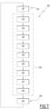
Fig 5 ] Lafigure 5 est une vue schématique en coupe verticale d'une partie du système de représentation de lafigure 1 comprenant plusieurs éléments mobiles, dont un est visible sur lafigure 5 , et un actuateur configuré pour déplacer cet élément mobile ; - [
Fig 6 ] lafigure 6 est une vue schématique en coupe verticale d'une partie du système de représentation de lafigure 1 comprenant un mécanisme électromagnétique configuré pour forcer les éléments mobiles dans une position de repos ; - [
Fig 7 ] lafigure 7 est un ordinogramme d'un procédé d'interaction mis en oeuvre par l'ensemble de lafigure 1 .
- [
Figure 1 ] therefigure 1 is a schematic perspective view of a representation assembly comprising a representation system according to the invention; - [
Figure 2 ] therefigure 2 is a schematic perspective view of part of the representation system of thefigure 1 ; - [
Figure 3 ] thereFigure 3 is a schematic perspective representation of part of the representation system of thefigure 1 comprising a positioning device; - [
Figure 4 ] thereFigure 4 is a schematic view of part of the positioning device of theFigure 3 ; - [
Figure 5 ] Therefigure 5 is a schematic view in vertical section of part of the representation system of thefigure 1 comprising several mobile elements, one of which is visible on thefigure 5 , and an actuator configured to move this mobile element; - [
Figure 6 ] thereFigure 6 is a schematic view in vertical section of part of the representation system of thefigure 1 comprising an electromagnetic mechanism configured to force the moving elements into a rest position; - [
Figure 7 ] thereFigure 7 is a flowchart of an interaction process implemented by the entirefigure 1 .
En référence aux
Le système de représentation 12 est configuré pour représenter une zone géographique 21 comprenant un relief.The
La zone géographique est par exemple une carte géographique. Selon un autre exemple, la zone géographique comprend des éléments urbains tels que des bâtiments.The geographical area is for example a geographical map. According to another example, the geographical area includes urban elements such as buildings.
Par « zone géographique comprenant un relief », il est entendu en particulier une zone géographique présentant trois dimensions.By “geographical area comprising a relief”, is meant in particular a geographical area having three dimensions.
En référence à la
La direction d'élévation Z s'étend perpendiculairement à une première direction, appelée direction transversale X dans ce qui suit, et une seconde direction, appelée direction longitudinale Y dans ce qui suit. Lorsque la direction transversale X et la direction longitudinale Y sont orientées horizontalement, la direction d'élévation Z est orientée verticalement.The elevation direction Z extends perpendicular to a first direction, called transverse direction X in the following, and a second direction, called longitudinal direction Y in the following. When the transverse direction X and the longitudinal direction Y are oriented horizontally, the elevation direction Z is oriented vertically.
Par exemple, lorsque le support 22 s'étend dans un plan horizontal, chaque élément mobile 24 est mobile en translation verticale par rapport au support 22.For example, when the
Par exemple, le système de représentation 12 comprend une table formée par le support 22 et des pieds, non représentés, supportant le support 22.For example, the
Le support 22 comprend par exemple un cadre 26, dont un exemple est illustré sur la
Chaque élément mobile 24 forme en particulier un « voxel » (mot composé du mot « vo » de « volume » et « xel » de « pixel », le mot « pixel » étant une contraction des termes anglais « picture » (pour image) et « élément » (pour élément)).Each
En référence à la
Selon un exemple, chaque élément mobile 24 présente une hauteur VZ sensiblement égale à 200 mm, dont la tête 30 présente une hauteur VE sensiblement égale à 30 mm. Par exemple, chaque tête 30 présente une même taille. Par exemple, chaque tête présente la face d'affichage 31 formant une partie du relief s'étendant dans un plan perpendiculaire à la direction d'élévation Z. Cette face d'affichage 31 présente par exemple une longueur VY et une largeur VX sensiblement égales à 5 mm.According to one example, each
Selon l'exemple, chaque tige 32 présente, dans un plan perpendiculaire à la direction d'élévation Z, une longueur VYB et une largeur VXB sensiblement égales à 3,5 mm.According to the example, each
Chaque élément mobile 24 est de préférence mobile entre une position de repos, dans laquelle chaque élément mobile 24 est positionné à une même hauteur prédéterminée par rapport au support 22 selon la direction d'élévation Z, et une pluralité de positions de saillie distinctes de la position de repos. Par exemple, dans la position de repos, les éléments mobiles 24 adhèrent au support 22.Each
Par exemple, en référence à la
De préférence, chaque élément mobile 24 est en contact par friction avec au moins un élément mobile voisin 24. En particulier, chaque élément mobile 24 est en contact par au moins une face latérale de la tête 30 avec l'élément mobile voisin 24. De préférence, une force de friction entre deux éléments mobiles voisins 24 est supérieure à une force de pesanteur desdits éléments mobiles 24. Cela permet de maintenir le ou chaque élément mobile 24 en position de saillie.Preferably, each
De préférence, chaque élément mobile 24 est fabriqué par fabrication additive.Preferably, each
De préférence encore, le support 22 est fabriqué par fabrication additive. Par exemple, le cadre 26 et la grille 28 sont fabriqués par fabrication additive, de préférence en une seule pièce.More preferably, the
Par exemple, chaque élément mobile 24 et/ou le support 22 est fait d'une matière plastique, en particulier d'une matière plastique rigide et matte.For example, each
De préférence, chaque élément mobile 24 est fait d'un même matériau que le support 22.Preferably, each
En référence à la
Le mécanisme électromagnétique 34 comprend par exemple un filet métallique 36, par exemple un filet de bobinage de cuivre. Le mécanisme électromagnétique 34 comprend par exemple pour chaque élément mobile 24 une base magnétique 38 fixée à la tête 30 de l'élément mobile 24 correspondant, notamment fixée sur une face de la tête 30 faisant face au filet métallique 36. Lorsque le filet métallique 36 reçoit un courant prédéterminé, il se comporte comme un électroaimant et attire chaque base magnétique 38 des éléments mobiles 24 et amène ainsi les éléments mobiles 24 dans la position de repos.The
Le système de représentation 12 comprend en outre au moins un actuateur 40 configuré pour déplacer successivement des différents éléments mobiles 24 de la pluralité d'éléments mobiles selon la direction d'élévation Z. En particulier, l'actuateur 40 est configuré pour déplacer l'un des éléments mobiles 24, puis un autre, respectivement selon la direction d'élévation Z.The
Par exemple, l'actuateur 40 est configuré pour recevoir une commande de déplacement pour déplacer l'élément mobile 24 concerné selon la direction d'élévation Z, en fonction de données tridimensionnelles du relief, notamment reçues du contrôleur 20 par une liaison de données.For example, the
Par exemple, en référence aux
L'actuateur 40 comprend par exemple un moteur d'actuateur 44 comprenant une roue dentée 46. Le moteur d'actuateur 44 est par exemple un moteur électrique. Lorsque le moteur d'actuateur 44 génère une rotation de la roue dentée 46, la crémaillère 42 se déplace en translation, illustré notamment sur la
Selon exemple non représenté, l'actuateur 40 est formé par un système pneumatique configuré pour déplacer successivement les différents éléments mobiles 24 de la pluralité d'éléments mobiles selon la direction d'élévation Z.According to an example not shown, the
Le système de représentation 12 comprend en outre un dispositif de positionnement 48 configuré pour positionner l'actuateur 40 par rapport aux éléments mobiles 24 dans un plan de positionnement perpendiculaire à la direction d'élévation Z.The
Le plan de positionnement est en particulier défini selon la direction transversale X et la direction longitudinale Y.The positioning plane is in particular defined according to the transverse direction X and the longitudinal direction Y.
Par exemple, le dispositif de positionnement 48 est configuré pour recevoir une commande de positionnement pour positionner l'actuateur 40 dans le plan de positionnement, notamment en fonction des données tridimensionnelles du relief, notamment reçues par une liaison de données adaptée de la part du contrôleur 20.For example, the
En référence à la
Selon un exemple, le dispositif de positionnement 48 comprend en outre un second moteur 56 configuré pour déplacer le bras 50 portant l'actuateur 40 selon la direction longitudinale Y dans le plan de positionnement, en particulier perpendiculairement à la direction transversale X. Dans ce cas, le dispositif de positionnement 48 par exemple une seconde courroie dentée 58 s'étendant selon la direction longitudinale Y.According to one example, the
Par exemple, le second moteur 56 est configuré pour déplacer le bras 50 par l'intermédiaire de la seconde courroie dentée 58. Ce déplacement de la seconde courroie dentée 58 est par exemple illustré sur la
Selon un exemple, le dispositif de positionnement 48 comprend en outre une barre métallique 60, s'étendant en particulier selon la direction longitudinale Y. En particulier, le bras 50 est porté d'un côté par la seconde courroie dentée 58 et de l'autre côté par la barre métallique 60.According to one example, the
L'actuateur 40 est configuré pour déplacer successivement certains des éléments mobiles 24 parmi la pluralité d'éléments mobiles 24 selon la direction d'élévation Z. En particulier, l'actuateur 40 est configuré pour déplacer l'un des éléments mobiles 24 à une première position de l'actuateur 40 dans le plan de positionnement, puis, après repositionnement de l'actuateur 40 par le dispositif de positionnement 48, un autre des éléments mobiles 24 à une seconde position de l'actuateur 40.The
L'actuateur 40 est notamment configuré pour déplacer l'élément mobile 24 à une position donnée par rapport au plan de positionnement par déplacement de la tige 32 par le moteur d'actuateur 44.The
En particulier, le dispositif de positionnement 48 est configuré pour déplacer l'actuateur 40 par combinaison des mouvements mis en oeuvre par le premier moteur 52 et le second moteur 56 dans le plan de positionnement par rapport aux éléments mobiles 24, notamment par déplacement du bras 50 et par déplacement de l'actuateur 40 sur ce bras 50.In particular, the
Selon un exemple non représenté, le système de représentation 12 comprend plusieurs actuateurs 40. Chaque actuateur 40 est de préférence tel que décrit ci-dessus.According to an example not shown, the
De préférence, le système de représentation 12 comprend un nombre d'actuateurs 40 strictement inférieur au nombre d'éléments mobiles 24 du système de représentation 12. Par exemple, le système de représentation 12 comprend un nombre N d'actuateurs, où N est un nombre de puissance de 2, tel que 2, 4, 8, 16, etc. De préférence, dans ce cas, le système de représentation 12 comprend un dispositif de positionnement 48 respectif pour chaque actuateur 40. Chaque dispositif de positionnement 48 est de préférence tel que décrit ci-dessus.Preferably, the
Par exemple, lorsque le système de représentation 12 comprend plusieurs actuateurs 40, chaque actuateur 40 est configuré pour déplacer respectivement les éléments mobiles 24 de manière successive d'une partie prédéfinie de la pluralité d'éléments mobiles 24, par exemple dans une zone prédéfinie du plan de positionnement. Dans ce cas, le dispositif de positionnement 48 respectif est configuré pour déplacer l'actuateur 40 correspondant dans la zone prédéfinie. De préférence, chaque actuateur 40 est inapte à déplacer les éléments mobiles en-dehors de sa zone prédéfinie.For example, when the
L'ensemble de représentation 10 comprend de préférence plusieurs dispositifs de pointage et commande 14. Le ou chaque dispositif de pointage et commande 14 est mobile par rapport au système de représentation 12.The
Le ou chaque dispositif de pointage et commande 14 est configuré pour pointer sur une position tridimensionnelle du relief du système de représentation 12. Par exemple, le ou chaque dispositif de pointage et commande 14 est configuré pour pointer sur une position présentant au moins un objet 62, et est configuré pour interagir avec cet objet 62 sur le relief de la zone géographique 21, par exemple configuré pour détailler ou modifier des attributs de l'objet 62, afficher une couche spécifique, notamment de la carte géographique, sur le relief ou déplacer l'objet 62.The or each pointing and
De préférence, le ou chaque dispositif de pointage et commande 14 est un composant COTS (de l'anglais « Commercial Off The Shelf »).Preferably, the or each pointing and
De préférence, le ou chaque dispositif de pointage et commande 14 est configuré pour émettre un signal non optique, en particulier un signal électromagnétique.Preferably, the or each pointing and
Chaque borne de détection 16 est configurée pour mesurer une position et/ou une orientation du dispositif de pointage et commande 14 par rapport au système de représentation 12.Each
Chaque borne de détection 16 est de préférence une borne électromagnétique configurée pour recevoir un signal électromagnétique du dispositif de pointage et commande 14 pour obtenir ladite mesure. Dans ce cas, le dispositif de pointage et commande 14 est en particulier configuré pour émettre le signal électromagnétique dans une bande de fréquences détectable par chaque borne de détection 16.Each
De préférence, l'ensemble de représentation 10 comprend un ou plusieurs dispositifs de projection 18, par exemple deux.Preferably, the
Le ou chaque dispositif de projection 18 est également appelé dispositif de vidéo projection.The or each
Le ou chaque dispositif de projection 18 est configuré pour projeter, sur le relief, une série d'images comprenant plusieurs objets 62.The or each
Les objets 62 à représenter sont fixes ou mobiles par rapport au relief.The
Les objets 62 sont par exemple modélisés dans le système de représentation 12 par une combinaison d'images numériques projetées (par exemple rendu de forme, couleur, texture, animation rapide) et d'éléments de relief physiques par les éléments mobiles 24 (par exemple rendu 3D, animation lente).The
Le contrôleur 20 comprend par exemple, non représenté, un module de réception, un module de traitement, et un module de sortie. De préférence, le module d'entrée, le module de traitement, et le module de sortie sont chacun réalisés au moins partiellement sous forme d'un logiciel, ou d'une brique logicielle, par exemple stocké dans une mémoire du contrôleur 20 et exécutable par un processeur du contrôleur 20.The
Le contrôleur 20 comprend par exemple une base de données, non représentée, dans laquelle sont stockées des données relatives à la zone géographique 21, par exemple des données cartographiques lorsque la zone est une carte géographique.The
Le contrôleur 20 est par exemple doté d'une interface homme-machine 64 comprenant par exemple un écran, un clavier et/ou une souris.The
Dans ce cas, selon un exemple, le contrôleur 20 est configuré pour recevoir les données via l'interface homme-machine 64, notamment des données cartographiques relatives à la carte géographique, en particulier relatives au relief, et/ou relatives aux objets 62.In this case, according to one example, the
Le contrôleur 20 est ainsi configuré pour élaborer la commande de déplacement pour l'actuateur 40 et/ou la commande de positionnement pour le dispositif de positionnement 48 à partir des données cartographiques, et configuré pour émettre cette ou ces commande(s).The
L'interface homme-machine 64 par exemple est en outre configurée pour afficher la zone géographique 21 et/ou des données relatives à la zone géographique 21 et les objets 62.The man-
Un procédé d'interaction 100 entre le dispositif de pointage et commande 14 et le système de représentation 12 va maintenant être décrit en référence à la
Le procédé d'interaction 100 est au moins partiellement mis en oeuvre par le contrôleur 20, c'est-à-dire est au moins partiellement mis en oeuvre par ordinateur.The
Le procédé d'interaction 100 comprend une phase de mesure 110, une phase de traitement 120, et une phase d'affichage 130.The
La phase de mesure 110 comprend au moins une étape de mesure 140 d'une position et d'une orientation du dispositif de pointage et commande 14.The
En particulier, lors de l'étape de mesure 140, la ou chaque borne de détection 16, notamment fixe par rapport au système de représentation 12, mesure la position et/ou l'orientation du dispositif de pointage et commande 14. Par exemple, chaque borne de détection 16 échange des données sans fil, de préférence par signal électromagnétique, avec le dispositif de pointage et commande 14 pour obtenir la mesure de la position et/ou de l'orientation de ce dispositif, par exemple selon un protocole d'échange de données prédéterminé, tel qu'un protocole mettant en oeuvre un réseau sans fil appelé « Wireless Gigabit (WiGig) », par exemple à une fréquence égale à 60 GHz.In particular, during the
De préférence, l'étape de mesure 140 est mise en oeuvre par au moins deux bornes de détection 16, ou trois ou quatre bornes de détection 16.Preferably, the
En particulier, un nombre augmenté de bornes de détection 16 permet de détecter la position et l'orientation de chaque dispositif de pointage et commande 14 situé autour de la table, même en présence d'un utilisateur ou d'un obstacle entre l'une des bornes de détection et le dispositif de pointage et commande 14 correspondant.In particular, an increased number of
Chaque borne de détection 16 transmet un signal comprenant la mesure au contrôleur 20.Each
La phase de traitement 120 est de préférence mise en oeuvre par le contrôleur 20.The
La phase de traitement 120 comprend une étape d'acquisition 142, une étape de réception 144, une étape de calcul 150, une étape de détermination 152, une étape d'élaboration 154, une étape d'émission 155, une première étape de réception de commande 156, et une seconde étape de réception de commande 157.The
Lors de l'étape d'acquisition 142, le contrôleur 20 acquiert une position de translation de chaque élément mobile 24. Par exemple, le contrôleur 20 reçoit une mesure de la position de translation de la part d'un capteur non représenté.During the
Selon un autre exemple, le contrôleur 20 obtient chaque position de translation d'une base de données non-représentée. Cette base de données comprend en particulier la position de translation de chaque élément mobile 24 mis à jour comme suite en déplacement récent selon la direction d'élévation Z de cet élément mobile 24.According to another example, the
Selon un autre exemple, le contrôleur 20 obtient chaque position de translation à partir d'un signal de la part du moteur d'actuateur 44.According to another example, the
Par « position de translation », il est entendu la position respective de chaque élément mobile 24 selon la direction d'élévation Z.By “translation position” is meant the respective position of each
Lors de l'étape de réception 144, le contrôleur 20 reçoit la mesure de la position et de l'orientation du ou des dispositif(s) de pointage et commande 14 par rapport au système de représentation 12. En particulier, le contrôleur 20 reçoit le signal comprenant la mesure de la part de la ou des bornes de détection 16, par une liaison de données adaptée.During the
Lors de l'étape de calcul 150, le contrôleur 20 calcule une ligne virtuelle 70 s'étendant à partir du dispositif de pointage et commande 14.During the
En particulier, le contrôleur 20 calcule la ligne virtuelle 70 à partir de la position du dispositif de pointage et commande 14 selon la mesure reçue lors de l'étape de réception 144, et à partir de l'orientation du dispositif de pointage et commande 14 selon la mesure reçue lors de l'étape 144.In particular, the
En particulier, le contrôleur 20 simule un espace tridimensionnel, et calcule dans cet espace la ligne virtuelle 70 en déterminant une équation de droite correspondant à une droite avec la position de la mesure et l'orientation de la mesure.In particular, the
La ligne virtuelle 70 calculée est ainsi orientée à partir de la position mesurée et selon l'orientation mesurée du dispositif de pointage et commande 14.The calculated
L'étape de calcul 150 est une étape optionnelle. Selon un exemple, à la place de l'étape de calcul 150, le contrôleur 20 accède à une base de données pour obtenir une ligne virtuelle pré-calculée en fonction de la position et de l'orientation du dispositif de pointage et commande 14 reçues lors de l'étape de réception 144.
Lors de l'étape de détermination 152, le contrôleur 20 détermine, en fonction de la mesure et de la position de translation de chaque élément mobile 24, une position tridimensionnelle.During the
La position tridimensionnelle forme une intersection de la ligne virtuelle 70 avec le relief de la zone géographique 21, par exemple avec la tête 30, notamment de la face d'affichage 31, de l'un des éléments mobiles 24.The three-dimensional position forms an intersection of the
En particulier, le contrôleur 20 détermine la position tridimensionnelle en fonction de l'élément mobile 24 ou des éléments mobiles 24 qui sont traversés par la ligne virtuelle 70.In particular, the
Par exemple, le contrôleur 20 simule le relief dans l'espace tridimensionnel, et calcule le point d'intersection de la ligne virtuelle 70 (notamment sous forme d'équation de droite) avec le relief simulé.For example, the
Lors de l'étape d'élaboration 154, le contrôleur 20 élabore un signal d'affichage en fonction de la position tridimensionnelle pour un affichage d'au moins une image de la zone géographique 21 sur le relief.During the
Par exemple, l'image comprise dans le signal d'affichage comprend un marquage de la position tridimensionnelle telle que calculée sur le relief.For example, the image included in the display signal includes a marking of the three-dimensional position as calculated on the relief.
Selon un exemple, l'image comprend l'objet 62 positionné à la position tridimensionnelle.According to one example, the image includes the
En référence à la
Selon un exemple, l'étape d'élaboration 154 comprend en outre un calcul de déformation d'image pour obtenir l'image du signal d'affichage, adaptée à la position de translation de chaque élément mobile 24.According to one example, the
En particulier, le contrôleur 20 met en oeuvre un traitement d'anamorphose, de préférence lorsque le fort relief et la déformation de la vidéo projection qui en résulte le justifie.In particular, the
Par exemple, le calculateur 20 déforme et/ou contracte des parties de l'image pour obtenir, sur le relief, l'affichage de l'image de manière non-déformée. En particulier, le contrôleur 20 compense des aberrations dues à la projection sur le relief, qui est non-plane et non-orthogonale à un axe d'un objectif du dispositif de projection 18 correspondant.For example, the
En particulier, le contrôleur 20 met en oeuvre des agrandissements ou contractions d'images en fonction des positions de translation de chaque élément mobile 24, pour obtenir l'image adaptée à la position de translation de chaque élément mobile 24.In particular, the
Lors de l'étape d'émission 155, le contrôleur 20 émet le signal d'affichage au ou à chaque dispositif de projection 18 pour l'affichage de l'image comprise dans le signal d'affichage sur le relief.During the
La première étape de réception de commande 156 et/ou la seconde étape de réception de commande 157 comprend/comprennent des modifications ou interactions avec l'objet 62 qui est pointé par le dispositif de pointage et commande 14. Cet objet 62 pointé est positionné à la position tridimensionnelle.The first
Lors de la première étape de réception 156, le contrôleur 20 reçoit, de la part du dispositif de pointage et commande 14, une commande d'interaction avec l'objet 62 positionné à la position tridimensionnelle, par exemple comme suite à un appui sur un bouton correspondant sur le dispositif de pointage et commande 14 pour envoyer la commande d'interaction au contrôleur 20.During the
La commande d'interaction est par exemple au moins un élément de la liste consistant en une modification d'un attribut de l'objet 62 positionné à la position tridimensionnelle, un affichage d'une information de l'objet 62 positionné à la position tridimensionnelle, un marquage de l'objet 62 à la position tridimensionnelle, et un déplacement de l'objet 62 sur le relief.The interaction command is for example at least one element of the list consisting of a modification of an attribute of the
Par exemple, lorsque la commande d'interaction comprend le déplacement de l'objet 62 sur le relief, l'utilisateur utilise le dispositif de pointage et commande 14 pour déplacer l'objet sur le relief de la position tridimensionnelle à une autre position. Cela est illustré sur la
Lorsque la commande d'interaction comprend une modification d'une donnée de l'objet 62, par exemple un attribut de l'objet est modifié. Par exemple, lorsque l'objet est un véhicule, une capacité de déplacement ou de communication du véhicule est modifiée par la commande d'interaction.When the interaction command includes a modification of data in the
Selon un exemple, le contrôleur 20 incorpore une telle modification dans le signal d'affichage, pour l'affichage de la donnée modifiée de l'objet 62.According to one example, the
Lorsque la commande d'interaction comprend un marquage de l'objet 62 à la position tridimensionnelle, le contrôleur 20 incorpore par exemple dans le signal d'affichage le marquage de l'objet 62, par exemple un changement de la couleur de l'objet 62, pour l'affichage de l'objet dans cette couleur.When the interaction command includes a marking of the
Lors de la seconde étape de réception de commande 157, le contrôleur 20 reçoit une commande d'affichage d'une couche prédéterminée du relief, notamment de la part du dispositif de pointage et commande 14.During the second
Selon un autre exemple de la seconde étape de réception de commande 157, ou en complément, cette étape comprend la réception par le contrôleur 20 d'une commande de marquage de la position tridimensionnelle, notamment de la part du dispositif de pointage et commande 14, par exemple comme suite à une saisie du bouton correspondant sur le dispositif de pointage et commande 14.According to another example of the second
Par exemple, en référence à la
En particulier le contrôleur 20 incorpore dans le signal d'affichage le marquage correspondant à la commande de marquage pour l'affichage de ce marquage sur le relief.In particular, the
Selon un exemple, le procédé d'interaction 100 comprend en outre une étape de programmation 158 de la zone géographique 21.According to one example, the
Par exemple, lors de l'étape de programmation 158, le contrôleur 21 reçoit, notamment par l'interface homme-machine 64, des données relatives à la zone géographique 21, telles que les données cartographiques relatives à la carte géographique.For example, during the
Le contrôleur 20 élabore la commande de déplacement pour l'actuateur 40 et/ou la commande de positionnement pour le dispositif de positionnement 48 à partir des données relatives à la zone géographique 21, et émet cette ou ces commande(s) lors de l'étape de programmation 158, pour obtenir le relief selon les données reçues, formant la zone géographique 21 en trois dimensions.The
Par exemple, le dispositif de positionnement 48 met en oeuvre le mouvement correspondant à la commande de positionnement en positionnant l'actuateur 40 en-dessous de l'élément mobile 24 correspondant. Selon un exemple, l'actuateur 40 met en oeuvre le mouvement correspondant à la commande de déplacement en déplaçant en translation l'élément mobile 24 correspondant.For example, the
De préférence, l'étape de programmation 158 est mise en oeuvre au moins une fois préalablement à la mise en oeuvre de l'étape de mesure 140 ou de l'étape d'acquisition 142.Preferably, the
La phase d'affichage 130 comprend une étape d'affichage 160 par le ou chaque dispositif de projection 18 de l'image comprise dans le signal d'affichage.The
De préférence, l'étape d'affichage 160 est mise en oeuvre par au moins deux dispositifs de projection 18. Cela permet d'obtenir l'affichage de l'image sur tous les éléments mobiles 24, et en particulier d'éviter un recouvrement de l'une des faces d'affichage 31 de l'élément mobile 24 correspondant par un autre élément mobile 24 en position de saillie, qui est par exemple agencé entre le dispositif de projection 18 et la face d'affichage 31 correspondante.Preferably, the
Le procédé d'interaction 100 est de préférence mis en oeuvre plusieurs fois. De préférence, la phase de mesure 110, la phase de traitement 120, et la phase d'affichage 130 sont mises en oeuvre successivement l'une après l'autre.The
De préférence, chaque phase 110, 120,130 est mise en oeuvre plusieurs fois.Preferably, each
Par exemple, au moins les étapes d'acquisition 142, de réception 144, de détermination 152, et d'élaboration 154 sont mises en oeuvre au moins une fois comme suite à une mise en oeuvre de l'étape de programmation 158.For example, at least the
Selon un exemple, la phase de mesure 110, la phase de traitement 120, et la phase d'affichage 130 sont mises en oeuvre simultanément ou en parallèle.According to one example, the
La phase de mesure 110 est optionnelle. En variante, le contrôleur 20 reçoit la mesure de la position et l'orientation sous forme d'une mesure simulée, par exemple à partir d'une base de données.Measuring
L'étape de calcul 150, l'étape d'émission 155, la première étape de réception de commande 156, la seconde étape de réception de commande 157 et/ou l'étape d'affichage 160 est/sont une/des étape(s) optionnelle(s).The
Bien entendu, d'autres modes de réalisation peuvent être envisagés.Of course, other embodiments can be considered.
Par exemple, le procédé 100 est mis en oeuvre par plusieurs dispositifs de commande 14.For example, the
Par exemple, le procédé d'interaction 100 comprend la réception de la commande de déplacement des éléments mobiles 24 en provenance du dispositif de pointage et commande 14 au lieu d'une saisie par l'interface homme-machine 64. Dans ce cas, par exemple, le dispositif de pointage et commande 14 envoie une commande adaptée au contrôleur 20, et le contrôleur 20 calcule un signal correspondant pour l'actuateur 40 correspondant et/ou pour le dispositif de projection 18.For example, the
On conçoit que le procédé d'interaction 100 est particulièrement simple à mettre en oeuvre pour un utilisateur, tout en permettant d'obtenir une perception tridimensionnelle effective de la zone géographique 21.We understand that the
Par exemple, si la position pointée, à savoir la position tridimensionnelle, contient la représentation d'un objet donné 62, et l'utilisateur envoie une commande pour obtenir des détails de cet objet 62, le signal affiché contient le nom de l'objet 62 et ses attributs. Selon un autre exemple, lors d'une modification du relief par une translation des éléments mobiles 24 selon la direction d'élévation Z, la position pointée par le dispositif de pointage et commande 14 est adaptée.For example, if the pointed position, namely the three-dimensional position, contains the representation of a given
Claims (10)
les bornes de détection (16) étant de préférence des bornes électromagnétiques recevant un signal électromagnétique du dispositif de pointage et commande (14) pour obtenir ladite mesure.Interaction method (100) according to any one of the preceding claims, further comprising a step of measuring (140) by at least two detection terminals (16) fixed relative to the representation system (12), of the position and the orientation of the pointing and control device (14) to obtain said measurement of the position and/or orientation of the pointing and control device (14),
the detection terminals (16) preferably being electromagnetic terminals receiving an electromagnetic signal from the pointing and control device (14) to obtain said measurement.
Applications Claiming Priority (1)
| Application Number | Priority Date | Filing Date | Title |
|---|---|---|---|
| FR2210854A FR3141262A1 (en) | 2022-10-20 | 2022-10-20 | Method for interacting a pointing and control device with a three-dimensional representation system, and associated representation assembly |
Publications (1)
| Publication Number | Publication Date |
|---|---|
| EP4357888A1 true EP4357888A1 (en) | 2024-04-24 |
Family
ID=85462151
Family Applications (1)
| Application Number | Title | Priority Date | Filing Date |
|---|---|---|---|
| EP23204659.9A Pending EP4357888A1 (en) | 2022-10-20 | 2023-10-19 | Method for interacting a pointing device and control with a three-dimensional representation system, and representation assembly therefor |
Country Status (2)
| Country | Link |
|---|---|
| EP (1) | EP4357888A1 (en) |
| FR (1) | FR3141262A1 (en) |
Citations (2)
| Publication number | Priority date | Publication date | Assignee | Title |
|---|---|---|---|---|
| US20200293112A1 (en) * | 2019-03-15 | 2020-09-17 | Technische Universität Dresden | System for haptic interaction with virtual objects for applications in virtual reality |
| WO2020249639A1 (en) * | 2019-06-13 | 2020-12-17 | Airbus Defence And Space Sas | Digital mission preparation system |
-
2022
- 2022-10-20 FR FR2210854A patent/FR3141262A1/en active Pending
-
2023
- 2023-10-19 EP EP23204659.9A patent/EP4357888A1/en active Pending
Patent Citations (2)
| Publication number | Priority date | Publication date | Assignee | Title |
|---|---|---|---|---|
| US20200293112A1 (en) * | 2019-03-15 | 2020-09-17 | Technische Universität Dresden | System for haptic interaction with virtual objects for applications in virtual reality |
| WO2020249639A1 (en) * | 2019-06-13 | 2020-12-17 | Airbus Defence And Space Sas | Digital mission preparation system |
Non-Patent Citations (1)
| Title |
|---|
| LEITHINGER DANIEL DANIELL@MEDIA MIT EDU ET AL: "Direct and gestural interaction with relief a 2.5D shape display", ACM 2012 CONFERENCE ON COMPUTER SUPPORTED COOPERATIVE WORK COMPANION, CSCW'12, ACM, USA, 16 October 2011 (2011-10-16), pages 541 - 548, XP058600350, ISBN: 978-1-4503-1051-2, DOI: 10.1145/2047196.2047268 * |
Also Published As
| Publication number | Publication date |
|---|---|
| FR3141262A1 (en) | 2024-04-26 |
Similar Documents
| Publication | Publication Date | Title |
|---|---|---|
| US11991342B2 (en) | Self-supervised training of a depth estimation system | |
| US10916063B1 (en) | Dockable billboards for labeling objects in a display having a three-dimensional perspective of a virtual or real environment | |
| US20180261012A1 (en) | Remote Object Detection and Local Tracking using Visual Odometry | |
| US10425762B1 (en) | Head-related impulse responses for area sound sources located in the near field | |
| JP6643357B2 (en) | Full spherical capture method | |
| US20220264173A1 (en) | Recording remote expert sessions | |
| CN103314344B (en) | Touch sensitive haptic display | |
| CN102750079B (en) | Terminal unit and object control method | |
| CN103597524B (en) | For inserting and strengthening the system and method that the message of user is shown to when browsing space for activities | |
| CA2942652C (en) | Three dimensional simulation system capable of creating a virtual environment uniting a plurality of users, and associated process | |
| CN101496033A (en) | Depth-varying light fields for three dimensional sensing | |
| KR20150108842A (en) | Mixed reality filtering | |
| CN102157011A (en) | Method for carrying out dynamic texture acquisition and virtuality-reality fusion by using mobile shooting equipment | |
| JP2009531655A5 (en) | ||
| US20220076373A1 (en) | Foveated rendering using eye motion | |
| CN109640070A (en) | A kind of stereo display method, device, equipment and storage medium | |
| CN112104595A (en) | Location-based application flow activation | |
| EP3983870B1 (en) | Digital mission preparation system | |
| EP4357888A1 (en) | Method for interacting a pointing device and control with a three-dimensional representation system, and representation assembly therefor | |
| EP4358069A1 (en) | System for representing a geographical area comprising a relief and assembly comprising such a representation system | |
| GB2547529A (en) | 3D digital content interaction and control | |
| FR3077910A1 (en) | METHOD FOR AIDING THE MAINTENANCE OF A COMPLEX SYSTEM | |
| US10789327B2 (en) | Method and apparatus of generating and providing page of data object information | |
| EP2671376A1 (en) | Method and device for processing sequences of images of a scene and system for monitoring a scene comprising such a device | |
| CN105787988A (en) | Information processing method, server and terminal device |
Legal Events
| Date | Code | Title | Description |
|---|---|---|---|
| PUAI | Public reference made under article 153(3) epc to a published international application that has entered the european phase |
Free format text: ORIGINAL CODE: 0009012 |
|
| STAA | Information on the status of an ep patent application or granted ep patent |
Free format text: STATUS: THE APPLICATION HAS BEEN PUBLISHED |
|
| AK | Designated contracting states |
Kind code of ref document: A1 Designated state(s): AL AT BE BG CH CY CZ DE DK EE ES FI FR GB GR HR HU IE IS IT LI LT LU LV MC ME MK MT NL NO PL PT RO RS SE SI SK SM TR |