EP4357809A1 - Method for calibrating the position of a camera and a lidar sensor with a calibration panel and a position calibration system - Google Patents
Method for calibrating the position of a camera and a lidar sensor with a calibration panel and a position calibration system Download PDFInfo
- Publication number
- EP4357809A1 EP4357809A1 EP23203375.3A EP23203375A EP4357809A1 EP 4357809 A1 EP4357809 A1 EP 4357809A1 EP 23203375 A EP23203375 A EP 23203375A EP 4357809 A1 EP4357809 A1 EP 4357809A1
- Authority
- EP
- European Patent Office
- Prior art keywords
- camera
- calibration
- lidar sensor
- image
- calibration board
- Prior art date
- Legal status (The legal status is an assumption and is not a legal conclusion. Google has not performed a legal analysis and makes no representation as to the accuracy of the status listed.)
- Pending
Links
- 238000000034 method Methods 0.000 title claims abstract description 82
- 238000002310 reflectometry Methods 0.000 claims description 29
- 238000012545 processing Methods 0.000 claims description 23
- 238000006243 chemical reaction Methods 0.000 claims description 13
- 238000006073 displacement reaction Methods 0.000 claims description 2
- 238000011161 development Methods 0.000 description 19
- 230000018109 developmental process Effects 0.000 description 19
- 238000001514 detection method Methods 0.000 description 12
- 238000005259 measurement Methods 0.000 description 10
- 230000009466 transformation Effects 0.000 description 10
- 238000012544 monitoring process Methods 0.000 description 7
- 238000001454 recorded image Methods 0.000 description 4
- 238000004519 manufacturing process Methods 0.000 description 3
- 230000011218 segmentation Effects 0.000 description 3
- 238000013459 approach Methods 0.000 description 2
- 238000009826 distribution Methods 0.000 description 2
- 238000012360 testing method Methods 0.000 description 2
- 230000002730 additional effect Effects 0.000 description 1
- 239000003086 colorant Substances 0.000 description 1
- 238000013461 design Methods 0.000 description 1
- ZINJLDJMHCUBIP-UHFFFAOYSA-N ethametsulfuron-methyl Chemical compound CCOC1=NC(NC)=NC(NC(=O)NS(=O)(=O)C=2C(=CC=CC=2)C(=O)OC)=N1 ZINJLDJMHCUBIP-UHFFFAOYSA-N 0.000 description 1
- 230000004907 flux Effects 0.000 description 1
- 230000004927 fusion Effects 0.000 description 1
- 230000006872 improvement Effects 0.000 description 1
- 238000012804 iterative process Methods 0.000 description 1
- 239000003550 marker Substances 0.000 description 1
- 230000003287 optical effect Effects 0.000 description 1
- 238000005457 optimization Methods 0.000 description 1
- 230000008569 process Effects 0.000 description 1
- 238000000275 quality assurance Methods 0.000 description 1
- 230000000717 retained effect Effects 0.000 description 1
- 238000000844 transformation Methods 0.000 description 1
- 230000000007 visual effect Effects 0.000 description 1
Images


Classifications
-
- G—PHYSICS
- G01—MEASURING; TESTING
- G01S—RADIO DIRECTION-FINDING; RADIO NAVIGATION; DETERMINING DISTANCE OR VELOCITY BY USE OF RADIO WAVES; LOCATING OR PRESENCE-DETECTING BY USE OF THE REFLECTION OR RERADIATION OF RADIO WAVES; ANALOGOUS ARRANGEMENTS USING OTHER WAVES
- G01S17/00—Systems using the reflection or reradiation of electromagnetic waves other than radio waves, e.g. lidar systems
- G01S17/86—Combinations of lidar systems with systems other than lidar, radar or sonar, e.g. with direction finders
-
- G—PHYSICS
- G01—MEASURING; TESTING
- G01S—RADIO DIRECTION-FINDING; RADIO NAVIGATION; DETERMINING DISTANCE OR VELOCITY BY USE OF RADIO WAVES; LOCATING OR PRESENCE-DETECTING BY USE OF THE REFLECTION OR RERADIATION OF RADIO WAVES; ANALOGOUS ARRANGEMENTS USING OTHER WAVES
- G01S17/00—Systems using the reflection or reradiation of electromagnetic waves other than radio waves, e.g. lidar systems
- G01S17/88—Lidar systems specially adapted for specific applications
- G01S17/93—Lidar systems specially adapted for specific applications for anti-collision purposes
- G01S17/931—Lidar systems specially adapted for specific applications for anti-collision purposes of land vehicles
-
- G—PHYSICS
- G01—MEASURING; TESTING
- G01S—RADIO DIRECTION-FINDING; RADIO NAVIGATION; DETERMINING DISTANCE OR VELOCITY BY USE OF RADIO WAVES; LOCATING OR PRESENCE-DETECTING BY USE OF THE REFLECTION OR RERADIATION OF RADIO WAVES; ANALOGOUS ARRANGEMENTS USING OTHER WAVES
- G01S7/00—Details of systems according to groups G01S13/00, G01S15/00, G01S17/00
- G01S7/48—Details of systems according to groups G01S13/00, G01S15/00, G01S17/00 of systems according to group G01S17/00
- G01S7/497—Means for monitoring or calibrating
- G01S7/4972—Alignment of sensor
Definitions
- the invention relates to a method for position calibration of a camera and a lidar sensor with a calibration board, as well as a position calibration system for position calibration of the camera and the lidar sensor.
- various types of obstacle detection systems are used in autonomous vehicles to detect obstacles.
- video cameras and lidar sensors are used to detect obstacles.
- the images generated by the obstacle detection systems are preferably evaluated together. It is important to know where a detected obstacle is located in an image taken by one obstacle detection system and in another image taken by the other obstacle detection system. The results of the obstacle detection systems should be able to be merged.
- mechanical tolerances when installing the obstacle detection systems are problematic.
- a small error in the alignment of the lidar sensor causes a large deviation at a distance of just 50 m.
- a detected obstacle in the image of the lidar sensor is suddenly in a completely different place.
- a detected collision is suddenly no longer a collision, and an obstacle detected outside the roadway can suddenly become a dangerous situation.
- the method according to the invention for position calibration of a camera and a lidar sensor using a calibration board is described below.
- the calibration board comprises known patterns. These known patterns have different brightnesses.
- the known pattern preferably comprises the colors black and white.
- additional reflection areas are applied to the calibration board, which have a higher reflectivity than the known patterns of different brightnesses. Reflectivity is the ratio between reflected and incident intensity as an energy quantity, for example in electromagnetic waves (luminous flux).
- a first process step at least one image of the calibration board is taken with the camera.
- the pose of the calibration board relative to the camera is determined based on the known patterns of different brightness.
- the term “pose” refers to the position and orientation of the calibration board, particularly in the camera coordinate system.
- a laser light is emitted from the lidar sensor onto the calibration board.
- a third process step at least one image is taken with the lidar sensor and the areas with high reflectivity are determined based on intensity values of the laser light reflected from the calibration panel.
- the pose of the calibration board relative to the lidar sensor is determined based on the known reflection areas and the identified areas with high reflectivity.
- the image with the camera and the image with the lidar sensor can be recorded in parallel.
- the process steps therefore do not represent a mandatory chronological sequence.
- the laser light must be emitted by the lidar sensor first before the pose of the calibration board relative to the lidar sensor can be determined.
- the pose of the calibration board relative to the camera can be determined in parallel.
- both images can then be converted into a common coordinate system (GCS) based on the determined poses.
- GCS common coordinate system
- the images taken by the camera and the lidar sensor are converted into a common coordinate system (GCS).
- an image taken by one sensor is converted into the coordinate system of the other image taken by the other sensor based on the determined poses.
- the image taken by the camera can be converted into the coordinate system of the image taken by the lidar sensor.
- a transformation takes place from the camera coordinate system (KKS) to the lidar coordinate system (LKS).
- the image taken by the lidar sensor can of course also be converted into the coordinate system of the image taken by the camera.
- a transformation takes place from the lidar coordinate system (LKS) to the camera coordinate system (KKS).
- conversion values are determined based on the determined poses in order to convert future images into a common coordinate system (GCS), or to convert a future image from one sensor into the coordinate system of the other image and thus of the other sensor.
- GCS common coordinate system
- a future image of the camera can be converted from the camera coordinate system (CCS) to the lidar coordinate system (LCS) using conversion values.
- a future image of the lidar sensor can be converted from the lidar coordinate system (LCS) to the camera coordinate system (CCS) using conversion values.
- a single calibration board can be used to determine the poses of the calibration board relative to the camera and relative to the lidar sensor. This makes it possible to convert images taken by the camera and/or the lidar sensor into the other coordinate system. If an object is detected in a camera image, it can be said immediately at which position in the lidar sensor image this object must be. The same applies to an object in the lidar sensor image. It can be said immediately at which position in the camera image this object must be.
- the calibration board can also simply comprise a painted wall.
- the calibration board is therefore not necessarily a separate structure that is set up in the room or hung on a wall.
- the position of objects in space can be determined. Additional properties can be determined from the camera images using object recognition or code and text reading. For example, it is possible to distinguish whether the object in the image is a person or not. Clear identification via a QR code is also possible. This could lead to more efficient anti-collision solutions, e.g. a person has to be driven around more slowly and carefully than a pallet. In addition or alternatively, documentation can be carried out for palletizing tasks, for example by simultaneously identifying goods loaded by an automated guided vehicle. Furthermore, an improvement in object detection can be achieved with anti-collision solutions. In the image of the lidar sensor, i.e.
- a small object e.g. a fork of a forklift
- the camera images i.e. the camera data
- the camera and the lidar sensor are arranged in a fixed position relative to one another. This means that the distance and alignment between the camera and the lidar sensor remain the same, i.e. constant. Nevertheless, it is possible for the camera and lidar sensor to be moved together. For example, they can be attached together to a vehicle that is moved autonomously. The distance and alignment of the camera and the lidar sensor to one another then corresponds to the distance and alignment between the camera and the lidar sensor during later operation.
- the camera and the lidar sensor record the respective image simultaneously. This means that the same scene is recorded.
- a time offset between the recording of the different images is preferably less than 1 second, 500 ms, 200 ms, 100 ms, 50 ms, 20 ms, 10 ms or less than 1 ms.
- the respective image of the camera and the lidar sensor have a time stamp, whereby time information from the time stamp can be used to say which images were taken by the lidar sensor and camera "simultaneously".
- the smallest possible time offset is achieved by synchronizing local timers of the lidar sensor and camera with an external timer or by making the time signal of an external timer available directly to the lidar sensor and the camera. By sorting the images of the lidar sensor and the camera based on their time stamps, the smallest possible time offset can then be achieved.
- the additional reflection areas comprise reflection strips. These are preferably glued to the calibration board.
- the additional reflection areas in particular in the form of the reflection strips, are aligned at an angle to one another.
- the reflection areas are not all aligned parallel to one another because otherwise it would not be possible to clearly identify the pose between the calibration board and the lidar sensor using laser lines that the lidar sensor emits in the form of laser light.
- the known patterns include ChArUco patterns.
- Such patterns can be used for both intrinsic calibration, such as estimating and correcting the lens distortion, focal length and/or focal point of the camera, and extrinsic calibration, such as determining the pose of the calibration board in the camera coordinate system.
- This method was developed, for example, by Garrido-Jurado, S., Mu-Salinas, R., Madrid-Cuevas, F., and Mar Jim z, M. (2014). "Automatic generation and detection of highly reliable fiducial markers under occlusion.” Pattern Recogn. 47, 6 (June 2014), 2280-2292 described.
- the open source library “opencv camera calibration (2022)” can be used for this. Opencv camera calibration (2022).
- Opencv camera calibration (2022). “Camera calibration with opencv, ⁇ https://docs.opencv.org/4.x/d4/d94/tutorial_camera_calibration.html>.
- the intrinsic camera calibration is determined directly from the camera recordings. This makes it much easier to use in practice, as the camera does not have to be calibrated beforehand. This means that cameras from other manufacturers can easily be introduced into the process, for example.
- a camera calibration that has to be carried out in advance always carries the risk that the optical properties of the camera system have changed in the period between the intrinsic calibration of the camera and the registration of the lidar sensor against the camera (e.g. due to vibration, focus adjustment and thermal expansion). Since the calibration board is small compared to the size of typical measuring rooms, the calibration board could also remain permanently in the measuring room in order to regularly check the measurement parameters by re-recording the calibration board with the lidar sensor and camera (quality assurance).
- a single calibration board is used to determine all calibration steps (camera: intrinsic and extrinsic, lidar sensor: extrinsic). This creates a direct link between the laser-related measurement areas (reflection areas) and the camera-related measurement areas (ChArUco pattern) directly via the calibration board. This increases the robustness of the method and avoids setup errors compared to other methods in which intrinsic and extrinsic calibration are carried out separately.
- the spatially compact design of the calibration board is suitable for use in industrial environments where the available space may be limited or some areas are difficult to access, making it impossible to set up complex calibration devices.
- the known patterns are localized on the calibration board in one step.
- the intrinsic parameters of the camera in particular focal length, focal point and/or lens distortion, are determined using the known patterns.
- the camera is then calibrated using the intrinsic parameters. The camera therefore does not have to be calibrated beforehand. This makes it much easier to use in practice.
- a large number of images are used to determine the intrinsic parameters of the camera. In this case, those images are discarded in which the projection error exceeds a threshold value.
- the camera takes pictures of the same scene.
- the relative position between the camera and the calibration board is preferably unchanged. Nevertheless, it is also conceivable that the position or orientation of the calibration board and/or the camera has changed in at least two of the images or in all of the images. Preferably, a certain number of images are also taken with the camera, this number being above a further threshold value. Further preferably, at least 2, 3, 6, 8, 12, 16, 20 or more than 25 images are used.
- the calibration board is placed in such a way that it is completely in the camera image and that it is crossed by a large number of laser lines, i.e. scan lines of the lidar sensor.
- the method is not limited to a lidar sensor that generates a certain number of laser lines, such as 4. It therefore also allows the use of lidar sensors with various point distribution characteristics, such as single-plane lidar sensors, or lidar sensors with pseudo-random point distributions.
- the lidar sensor In a further development of the method for position calibration, the lidar sensor generates more than 2, 3, 4 or more than 5 laser lines. These laser lines preferably run parallel to each other and are preferably generated simultaneously. This makes it possible to determine the pose, i.e. the position and alignment of the calibration board to the lidar sensor, very precisely, because different laser lines cross different reflection areas. In particular, if the reflection areas are aligned at an angle to each other, the pose of the calibration board relative to the lidar sensor can be determined very precisely.
- a curvature of the laser lines is compensated by a known or calculated deviation from a straight laser line.
- the laser line that the lidar sensor projects onto the calibration board is, strictly speaking, not a straight line, but a flatly curved hyperbola.
- the deviation from a straight line is not too great, but it is still possible to take the curvature of the hyperbola into account. This can be achieved, among other things, by taking the deviation from a straight laser line from a look-up table.
- the look-up table is calculated and saved once for each laser line.
- a step is used to determine which sections of the reflected laser lines have an intensity profile that is above a threshold value and which sections of the reflected laser lines lie in one plane. Sections above the threshold value are areas with high reflectivity. This is how a binarization of the intensity profile is carried out. All additional reflection areas on the calibration board lie in one plane. Such an image must also result from the reflected laser lines. Points in space are determined for the reflected laser lines (e.g. X, Y, Z) and a corresponding intensity value is determined for each point. Furthermore, the reflectivity of the additional reflection areas are higher than the surroundings. In a further process step, the sections determined in this way are compared with the known additional reflection areas. It is known, or it has been determined from at least one image from the camera, where the additional reflection areas are located on the calibration board. This allows the calibration board to be discovered in the image from the lidar sensor.
- the adjustment takes place by determining a displacement and a rotation angle of the determined sections relative to the origin of the calibration table in order to determine the pose of the calibration table relative to the lidar sensor.
- the reflected laser lines can be shifted in the plane until the areas of the reflected laser lines whose intensity values are above a threshold value correspond to the areas on the calibration table where the additional reflection areas are arranged. This can be done using an iterative process in which the reflected laser lines are also rotated.
- data from at least one radar sensor could also be included.
- the calibration panel could also include radar reflectors. These radar reflectors can be active or passive radar reflectors.
- the camera and/or the lidar sensor are arranged in a fixed position.
- the position and the alignment between the camera and the lidar sensor are also fixed and are not changed.
- the calibration board can be moved while different images are taken by the camera and the lidar sensor.
- the calibration board can be arranged in a fixed position. In this case, a combination of camera and lidar sensor, whereby the position and alignment between camera and lidar sensor remains unchanged. As a result, the alignment between calibration board and camera / lidar sensor differs in the individual images.
- test calibration boards can be set up.
- the position calibration can be checked using these test calibration boards.
- the lidar sensor can comprise an azimuth detection field of more than 120°, 180° or more than 240°.
- the azimuth detection field can also be 360°.
- at least one further camera and at least one further calibration board are used. More than one additional camera could also be used. In this case, all cameras could be compared against the lidar sensor. The method would then allow all images to be converted into a common coordinate system based on the determined poses. It would also be conceivable that the images from at least two but not all sensors would be converted into the coordinate system of the remaining sensor (e.g. the lidar sensor). In principle, it would also be possible that in this case conversion values could also be determined in order to convert future images into a common coordinate system. It would also be possible that conversion values could be determined in order to convert a future image into the coordinate system of another future image from another sensor.
- the pose of the calibration board relative to the lidar sensor could also be optimized using additional prior knowledge.
- a Monte Carlo search can be used to determine the desired pose.
- the search space can then be optimized based on the pose of the calibration board relative to the lidar sensor determined during the extrinsic camera calibration.
- Camera can be significantly restricted. This is based on the assumption that the lidar sensor and camera are close to each other, or that their position relative to each other is roughly known. However, this is not a mandatory restriction and merely reduces the search effort in the parameter space.
- the remaining free parameters are essentially limited to the angle of deviation from the horizontal of at least one laser line that sweeps over the calibration board and its height on the calibration board.
- a distance measure is then used as an optimization criterion, such as the Hamming distance, which indicates the distance between the recorded intensity values of the reflected laser light that are above a threshold value and the position of the additional reflection areas predicted using the current transformation.
- a position and/or the alignment of the calibration board relative to a combination of camera and lidar sensor can be changed.
- the calibration board is preferably moved around the combination of camera and lidar sensor.
- the combination of camera and lidar sensor could also be moved around the calibration board.
- the distance and alignment between the camera and lidar sensor remains unchanged.
- the camera and lidar sensor then take pictures again and the pose of the calibration board relative to the camera and lidar sensor is determined again. This makes it possible, for example, to determine more precise conversion values.
- the position calibration system comprises a camera, a lidar sensor, a calibration board and a processing unit.
- the calibration board has known patterns, wherein the known patterns comprise different brightnesses. Additional reflection areas are applied to the calibration board, which have a higher reflectivity than the known patterns of different brightnesses.
- the camera is designed to take an image of the calibration board, wherein the processing unit is designed to determine a pose of the calibration board relative to the camera based on the known patterns. This known patterns are recorded in the camera image.
- the lidar sensor is designed to emit a laser light onto the calibration board.
- the lidar sensor is further designed to take an image, wherein the processing unit is designed to determine areas with high reflectivity based on intensity values of the laser light reflected from the calibration board.
- the processing unit is designed to convert both images into a common coordinate system (GKS) based on the determined poses.
- the processing unit is designed to convert one image into the coordinate system of the other image based on the determined poses.
- the processing unit is designed to determine conversion values based on the determined poses in order to convert future images into a common coordinate system (GKS) or to convert a future image from one sensor (camera or lidar sensor) into the coordinate system of another future image from the other sensor (lidar sensor or camera). Provision can be made to transform the lidar data into a 2D image coordinate system. Also, the position of at least some pixels in the 2D image coordinate system could be transformed into the 3D system.
- an autonomously driving vehicle in particular in the form of a forklift truck, is specified.
- the autonomously driving vehicle comprises a camera, a lidar sensor and a processing unit.
- the camera and the lidar sensor are calibrated to one another according to one of the preceding claims and are arranged on the vehicle so that they are relatively immovable to one another.
- the lidar sensor is designed to continuously monitor the roadway, in particular in front of the vehicle, for obstacles.
- the processing unit is designed to compare at least one object in the data (images) of the lidar sensor, which is e.g.
- the warning can be visual and/or acoustic and/or haptic, e.g. through vibrations.
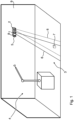
- FIG. 1 shows the use of a camera 1 and a lidar sensor 2, which together monitor a spatial area 3 of a production environment.
- a robot 4 is shown in the production environment.
- the spatial area 3 in which the robot 4 is located is monitored with the camera 1 and the lidar sensor 2.
- the camera 1 and the lidar sensor 2 are arranged in a common housing 5. However, they can also be housed in different housings.
- Both the camera 1 and the lidar sensor 2 have a monitoring field 6.
- the monitoring field 6 of the camera 1 is shown with a solid line
- the monitoring field 6 of the lidar sensor 2 is shown with a dotted line. Both monitoring fields 6 are aligned so that they overlap one another, at least partially.
- the data from camera 1 and the data from lidar sensor 2 can be fused so that it can be said immediately where a detected object 7 in the data from camera 1 must appear in the data from lidar sensor 2 and vice versa.
- This fusion can be carried out using a processing unit 8, which is arranged, for example, in the common housing 5.
- the common housing 5 is attached to a wall 9.
- Camera 1 can be a photo camera or a video camera.
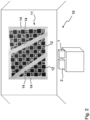
- a position calibration system 10 is shown with the camera 1, the lidar sensor 2 and a calibration board 11.
- the calibration board 11 comprises known patterns 12 of different brightness.
- the known patterns 12 are preferably ChArUco patterns. These comprise a checkerboard structure with ArUco patterns.
- the patterns 12 themselves are known in terms of size and orientation to one another.
- the camera 1 and the lidar sensor 2 are fixed in position, i.e. cannot be moved relative to each other. This arrangement is retained after position calibration, i.e. when used in an autonomously driving vehicle.
- the camera 1 takes an image 13 in which the calibration board 11 is located.
- the processing unit 8 it is possible to determine a pose of the calibration board 11 relative to the camera 1. This is done by detecting the known patterns 12.
- the determination of the pose (position and orientation) of the calibration board 11 relative to the camera 1 is also referred to as extrinsic camera calibration.
- an intrinsic camera calibration can also be carried out using the recorded image 13. In particular, the focal length, focal point and/or lens distortion are determined. This works based on the detected known patterns 12. The camera 1 therefore does not have to be pre-calibrated.
- the structure consisting of camera 1 and lidar sensor 2 is moved around the calibration board 11 so that several images 13 are recorded by the camera 1 from different angles on the calibration board 11.
- the calibration board 11 could also be moved in addition or as an alternative.
- the calibration panel 11 comprises additional reflection areas 14 which have a higher reflectivity than the known patterns 12.
- additional reflection areas 14 comprise in particular several reflection strips.
- the reflection strips are at least partially aligned at an angle to one another.
- the known patterns 12 can be partially covered by the additional reflection areas 14, for example glued over.
- the lidar sensor 2 records an image 15 in which the calibration plate 11 is located. This is done by emitting laser light 16, in particular in the form of several laser lines 17.
- the reflected laser light 16 in the form of the laser lines 17 is visible in the recorded image 15 of the lidar sensor 2.
- areas 18 with high reflectivity. This is done using intensity values of the laser light 16 reflected by the calibration panel 11.
- the processing unit 8 is designed to determine a pose of the calibration panel 11 relative to the lidar sensor 2 using the known reflection areas 14 and the determined areas 18 with high reflectivity.
- the structure consisting of camera 1 and lidar sensor 2 is moved around the calibration board 11 so that several images 15 are recorded by the lidar sensor 2 from different angles on the calibration board 11.
- the calibration board 11 could also be moved in addition or as an alternative.
- the camera 1 and the lidar sensor 2 preferably take images 13, 15 from the calibration panel 11 synchronously with each other.
- the lidar sensor 2 cross the Calibration board 11 and thus the additional reflection areas 14. Because the additional reflection areas 14 comprise reflection strips aligned at an angle to one another, the reflected laser light 16 can be used to precisely determine which part of the calibration board 11 was crossed by the laser lines 17.
- the lidar sensor 2 preferably emits more than two, three, four or more than five laser lines 17, which are preferably arranged parallel to one another.
- the laser lines 17 are preferably arranged completely without overlapping one another.
- the processing unit 8 is further designed to convert both images 13, 15 into a common coordinate system (GCS) based on the determined poses. In this case, it can be said very precisely where an object 7 is located.
- GCS common coordinate system
- the processing unit 8 is designed to convert an image 13, 15 into the coordinate system of the other image 15, 13 based on the determined poses. It can then also be determined in which area of the other image 15, 13 the object 7 must be located.
- the processing unit 8 is designed in particular to determine conversion values based on the determined poses in order to use the conversion values to convert future images 13, 15 into a common coordinate system (GKS).
- GKS common coordinate system
- the conversion values can also be used to convert a future image 13, 15 into the coordinate system of the other image 15, 13. This makes it possible to efficiently merge both images 13, 15 and detected objects 7 in one image 13, 15 can be verified using the other image 15, 13.
- Figure 5 shows a recorded image 15 of the lidar sensor 2.
- the image 15 contains the reflected laser light 16 with the laser lines 17 that the lidar sensor 2 emitted.
- the image 15 there are areas with high reflectivity 18, i.e. areas with high light intensity. These areas with high reflectivity 18 come about because the laser light 16, i.e. the laser lines 17 emitted by the lidar sensor 2, hit the additional reflection areas 14 of the calibration panel 11.
- areas with low reflectivity 19 are shown. In these areas, the intensity of the reflected laser light 16 is lower than in the areas with high reflectivity 18.
- the laser lines 17 emitted by the lidar sensor 2 hit areas of the calibration panel 11 that absorb a higher light output.
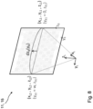
- FIG 6 This is illustrated using another exemplary embodiment.
- the additional reflection areas 14 are drawn on the calibration board 11.
- the known patterns 12 have been omitted in this case for better clarity.
- the reflected laser light 16 is shown in the form of laser lines 17.
- the reflected laser light 16 has a varying intensity profile, depending on which areas of the calibration board the laser light 16 has struck. Areas with high reflectivity 18, i.e. a high intensity value, are shown brighter than areas with low reflectivity 19.
- the processing unit 8 can analyze the image 15 of the lidar sensor 2 to find out in which area the calibration board 11 is located and how the calibration board 11 must be aligned relative to the lidar sensor 2 so that the detected areas with high reflectivity 18 match the known additional reflection areas 14 of the calibration board 11. This is explained in more detail below.
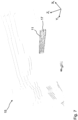
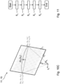
- Figure 7 shows an image 15 of the lidar sensor 2 in which the calibration table 11 is located.
- the measurement data of the lidar sensor 2 are preferably transformed into Cartesian coordinates so that the 3D position in lidar coordinates and its intensity value are known for each measuring point.
- the image 15 of the lidar sensor 2 therefore comprises a large number of measuring points.
- the set of all measuring points can also be referred to as a point cloud.
- the calibration table 11 is now iteratively located in the point cloud.
- the measuring point P max with the highest intensity value is searched for. It is examined whether this point lies within a plane. The detection of such a plane in the point cloud is carried out using known methods, e.g.
- the search area can be restricted by specifying a 3D cuboid in order to avoid errors due to reflections or artifacts.
- the intensity values of the measurement points lying on the flat surface are then binarized. Binarization is carried out using an intensity histogram.
- the binarization threshold is determined so that the percentage of bright points (intensities above the threshold) corresponds to the reflective portion on the calibration panel 11.
- the ratio of reflective to non-reflective points on the calibration panel 11 is known and constant (width of the reflective strips of the additional reflective areas 14 relative to the width of the calibration panel 11).
- Such a binarization of the lidar point cloud on the calibration panel is e.g. in Figure 5 shown.
- the lidar sensor 2 does not scan the space in a plane, but through a flat cone.
- the laser line 17 that the lidar sensor 2 projects onto the calibration board 11 is therefore not a straight line, but a flatly curved hyperbola.
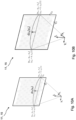
- the Figures 10A, 10B and 10C show the iteration over a curved laser line by moving the start and end points.
- the areas with high reflectivity 18 of the reflected laser light 16 in the form of the laser lines 17 lie exclusively or more than 90%, 95% or more than 98% above the additional reflection areas 14.
- the curvature of the hyperbola is taken into account by taking the deviation from the straight laser line 17, for example, from a lookup table.
- the lookup table can be calculated and saved once for each laser line 17.
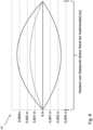
- Figure 9 shows the deviation of the hyperbolas from the straight laser line 17, which is stored in the lookup table.
- the width of the graphic corresponds approximately to the width of the calibration table 11. The figure is shown exaggerated in the Y direction. Even if the deviations between the intersection hyperbola and an approximate intersection line are small, taking the hyperbola intersection into account increases the accuracy of the image.
- the difference dz B (y B ) to the straight laser line 17 is stored in the lookup table for each value y B.
- P Board (y Board , z Board ) (in the board reference system). Since the pose of the calibration board 11 in the camera coordinate system is also known, a transformation T Board ⁇ Camera can also be calculated.
- a transformation T Li-dar ⁇ Camera can be estimated using known methods (least mean square), which converts each measurement point in lidar coordinates into a 3D point. in camera coordinates (ie no longer just the points on the calibration board).
- the 3D transformation can be estimated, for example, as described in opencv pose estimation (see opencv pose estimation (2022)). Using the determined intrinsic camera parameters, the 3D camera points can be transformed into 2D image points.
- Figure 11 shows a flow chart describing a method for position calibration of the camera 1 and the lidar sensor 2 with the calibration board 11.
- a first method step S 1 at least one image 13 of the calibration board 11 is recorded with the camera 1 and a pose of the calibration board 11 relative to the camera 1 is determined based on the known patterns 12 on the calibration board 11.
- laser light 16 in particular in the form of laser lines 17, is radiated from the lidar sensor 2 onto the calibration panel 11.
- a third method step S 3 an image 15 is taken of the calibration panel 11 using the lidar sensor 2, and areas with high reflectivity 18 are determined based on intensity values of the laser light 16 reflected from the calibration panel 11, in particular in the form of the laser lines 17.
- a pose of the calibration panel 11 relative to the lidar sensor 2 is determined based on the known additional reflection areas 14 and the determined areas with high reflectivity 18.
- both images 13, 15 can be converted into a common coordinate system (GKS) based on the determined poses.
- one image 13, 15 can be converted into the coordinate system of the other image 15, 13 based on the determined poses.
- an image 13 from camera 1 can be converted into the lidar coordinate system (LKS) of lidar sensor 2.
- an image 15 from lidar sensor 2 can be converted into the camera coordinate system (KKS) of camera 1.
- conversion values are determined based on the determined poses in order to convert future images 13, 15 into a common coordinate system (GKS) or to convert a future image 13, 15 into the coordinate system of another future image 15, 13.
Abstract
Das Verfahren zur Positionskalibrierung dient zur Fusionierung von Bildern (13, 15) einer Kamera (1) und eines Lidarsensors (2). Die Kamera (1) nimmt ein Bild (13) von einer Kalibriertafel (11) auf, wobei anhand bekannter Muster (12) die Pose der Kalibriertafel (11) relativ zur Kamera (1) ermittelbar ist. Der Lidarsensor (2) nimmt ein Bild (15) der Kalibriertafel (11) auf, wobei anhand zusätzlicher Reflektionsbereiche (14) auf der Kalibriertafel (11) eine Pose der Kalibriertafel (11) relativ zum Lidarsensor (2) ermittelbar ist. Anhand beider Posen können im Folgenden Bilder (13, 15), die von der Kamera (1) und/oder dem Lidarsensor (2) aufgenommen werden, jeweils in ein gemeinsames Koordinatensystem oder in das Koordinatensystem des anderen Bildes (13, 15) umgerechnet werden. Dadurch können Objekte (7), die in einem Bild (13, 15) detektiert werden, in einem anderen Bild (15, 13) verifiziert werden.The method for position calibration is used to fuse images (13, 15) of a camera (1) and a lidar sensor (2). The camera (1) records an image (13) of a calibration board (11), wherein the pose of the calibration board (11) relative to the camera (1) can be determined using known patterns (12). The lidar sensor (2) records an image (15) of the calibration board (11), wherein a pose of the calibration board (11) relative to the lidar sensor (2) can be determined using additional reflection areas (14) on the calibration board (11). Based on both poses, images (13, 15) recorded by the camera (1) and/or the lidar sensor (2) can then be converted into a common coordinate system or into the coordinate system of the other image (13, 15). This allows objects (7) detected in one image (13, 15) to be verified in another image (15, 13).
Description
Die Erfindung betrifft ein Verfahren zur Positionskalibrierung einer Kamera und eines Lidarsensors mit einer Kalibriertafel, sowie ein Positionskalibrierungssystem zur Positionskalibrierung der Kamera und des Lidarsensors.The invention relates to a method for position calibration of a camera and a lidar sensor with a calibration board, as well as a position calibration system for position calibration of the camera and the lidar sensor.
Unter anderem werden in autonom fahrenden Fahrzeugen zur Hinderniserkennung verschiedene Arten von Hinderniserkennungssystemen eingesetzt. So werden beispielsweise Videokameras und Lidarsensoren verwendet, um Hindernisse detektieren zu können. Die Bilder, die die Hinderniserkennungssysteme erzeugen, werden vorzugsweise gemeinsam ausgewertet. Dabei ist es wichtig zu wissen, wo sich ein erkanntes Hindernis auf einem Bild, welches von einem Hinderniserkennungssystem aufgenommen wurde, in einem anderen Bild, welches von dem anderen Hinderniserkennungssystem aufgenommen wurde, befindet. Die Ergebnisse der Hinderniserkennungssysteme sollen fusioniert werden können. Problematisch sind allerdings mechanische Toleranzen beim Einbau der Hinderniserkennungssysteme, wie dies bei der Montage eines Fahrzeugs der Fall ist. Ein kleiner Fehler in der Ausrichtung des Lidarsensors bewirkt eine große Abweichung in einer Entfernung von bereits 50 m. Ein detektiertes Hindernis im Bild des Lidarsensors befindet sich plötzlich an einer ganz anderen Stelle. Eine detektierte Kollision ist plötzlich keine mehr und aus einem Hindernis, welches außerhalb der Fahrbahn detektiert wurde kann plötzlich eine gefährliche Situation entstehen.Among other things, various types of obstacle detection systems are used in autonomous vehicles to detect obstacles. For example, video cameras and lidar sensors are used to detect obstacles. The images generated by the obstacle detection systems are preferably evaluated together. It is important to know where a detected obstacle is located in an image taken by one obstacle detection system and in another image taken by the other obstacle detection system. The results of the obstacle detection systems should be able to be merged. However, mechanical tolerances when installing the obstacle detection systems, as is the case when assembling a vehicle, are problematic. A small error in the alignment of the lidar sensor causes a large deviation at a distance of just 50 m. A detected obstacle in the image of the lidar sensor is suddenly in a completely different place. A detected collision is suddenly no longer a collision, and an obstacle detected outside the roadway can suddenly become a dangerous situation.
Aus
Nachteilig an diesem Verfahren ist, dass die Kamera bereits kalibriert sein muss. Zudem ist der Kalibrierungswürfel groß und unhandlich, was die Anwendung in der Praxis erschwert.The disadvantage of this method is that the camera must already be calibrated. In addition, the calibration cube is large and unwieldy, which makes it difficult to use in practice.
Es ist daher die Aufgabe der hier vorliegenden Erfindung ein Verfahren zur Positionskalibrierung einer Kamera und eines Lidarsensors zu schaffen, welches besonders effizient ausgeführt werden kann.It is therefore the object of the present invention to provide a method for position calibration of a camera and a lidar sensor, which can be carried out particularly efficiently.
Die Aufgabe wird durch das Verfahren zur Positionskalibrierung einer Kamera und eines Lidarsensors mit einer Kalibriertafel gemäß dem unabhängigen Anspruch 1, sowie durch das Positionskalibrierungssystem gemäß dem Anspruch 14 gelöst. Die Ansprüche 2 bis 13 beschreiben vorteilhafte Weiterbildungen des Verfahrens und der Anspruch 15 beschreibt ein autonom fahrendes Fahrzeug, welches eine positionskalibrierte Kamera nebst Lidarsensor umfasst.The object is achieved by the method for position calibration of a camera and a lidar sensor with a calibration board according to
Nachfolgend wird das erfindungsgemäße Verfahren zur Positionskalibrierung einer Kamera und eines Lidarsensors mit einer Kalibriertafel beschrieben. Die Kalibriertafel umfasst bekannte Muster. Diese bekannten Muster weisen eine unterschiedliche Helligkeit auf. Vorzugsweise umfasst das bekannte Muster die Farben schwarz und weiß. Weiterhin sind zusätzliche Reflektionsbereiche auf der Kalibriertafel aufgebracht, die eine höhere Reflektivität aufweisen als die bekannten Muster unterschiedlicher Helligkeit. Unter Reflektivität ist das Verhältnis zwischen reflektierter und einfallender Intensität als Energiegröße, zum Beispiel bei elektromagnetischen Wellen (Lichtstrom) zu verstehen.The method according to the invention for position calibration of a camera and a lidar sensor using a calibration board is described below. The calibration board comprises known patterns. These known patterns have different brightnesses. The known pattern preferably comprises the colors black and white. Furthermore, additional reflection areas are applied to the calibration board, which have a higher reflectivity than the known patterns of different brightnesses. Reflectivity is the ratio between reflected and incident intensity as an energy quantity, for example in electromagnetic waves (luminous flux).
In einem ersten Verfahrensschritt wird zumindest ein Bild von der Kalibriertafel mit der Kamera aufgenommen. Dabei wird die Pose der Kalibriertafel relativ zur Kamera anhand der bekannten Muster unterschiedlicher Helligkeit ermittelt. Unter dem Begriff "Pose" wird die Position und Orientierung der Kalibriertafel, insbesondere im Kamerakoordinatensystem verstanden.In a first process step, at least one image of the calibration board is taken with the camera. The pose of the calibration board relative to the camera is determined based on the known patterns of different brightness. The term "pose" refers to the position and orientation of the calibration board, particularly in the camera coordinate system.
In einem zweiten Verfahrensschritt wird ein Laserlicht vom Lidarsensor auf die Kalibriertafel ausgesendet. Insbesondere ist darunter zu verstehen, dass das Laserlicht vom Lidarsensor nicht nur auf die Kalibriertafel, sondern auch noch auf die die Kalibriertafel umgebenden Bereiche ausgesendet wird.In a second process step, a laser light is emitted from the lidar sensor onto the calibration board. In particular, this means that the laser light from the lidar sensor is emitted not only onto the calibration board, but also onto the areas surrounding the calibration board.
In einem dritten Verfahrensschritt wird zumindest ein Bild mit dem Lidarsensor aufgenommen und die Bereiche mit hoher Reflektivität anhand von Intensitätswerten des von der Kalibriertafel zurückgestrahlten Laserlichts ermittelt.In a third process step, at least one image is taken with the lidar sensor and the areas with high reflectivity are determined based on intensity values of the laser light reflected from the calibration panel.
In einem vierten Verfahrensschritt wird die Pose der Kalibriertafel relativ zum Lidarsensor anhand der bekannten Reflektionsbereiche und den ermittelten Bereichen mit hoher Reflektivität ermittelt.In a fourth process step, the pose of the calibration board relative to the lidar sensor is determined based on the known reflection areas and the identified areas with high reflectivity.
Grundsätzlich können das Bild mit der Kamera und das Bild mit dem Lidarsensor parallel aufgenommen werden. Die Verfahrensschritte stellen daher keine zwingende zeitliche Abfolge dar. Selbstverständlich muss das Laserlicht vom Lidarsensor zuerst ausgesendet werden, bevor die Pose der Kalibriertafel relativ zum Lidarsensor ermittelt werden kann. Die Ermittlung der Pose der Kalibriertafel relativ zur Kamera kann allerdings parallel dazu erfolgen.In principle, the image with the camera and the image with the lidar sensor can be recorded in parallel. The process steps therefore do not represent a mandatory chronological sequence. Of course, the laser light must be emitted by the lidar sensor first before the pose of the calibration board relative to the lidar sensor can be determined. However, the pose of the calibration board relative to the camera can be determined in parallel.
Im Anschluss daran können in einer ersten Alternative beide Bilder anhand der ermittelten Posen in ein gemeinsames Koordinatensystem (GKS) umgerechnet werden. In diesem Fall werden die Bilder, die von der Kamera und vom Lidarsensor aufgenommen wurden, in ein gemeinsames Koordinatensystem (GKS) umgerechnet.In a first alternative, both images can then be converted into a common coordinate system (GCS) based on the determined poses. In this case, the images taken by the camera and the lidar sensor are converted into a common coordinate system (GCS).
In einer zweiten Alternative wird ein Bild, welches von einem Sensor aufgenommen wurde, anhand der ermittelten Posen in das Koordinatensystem des anderen Bildes, welches vom anderen Sensor aufgenommen wurde, umgerechnet. So kann das Bild, welches von der Kamera aufgenommen wurde, in das Koordinatensystem des Bildes umgerechnet werden, welches vom Lidarsensor aufgenommen wurde. In diesem Fall findet eine Transformation vom Kamerakoordinatensystem (KKS) in das Lidarkoordinatensystem (LKS) statt. Umgekehrt kann natürlich auch das Bild, welches von dem Lidarsensor aufgenommen wurde, in das Koordinatensystem des Bildes umgerechnet werden, welches von der Kamera aufgenommen wurde. In diesem Fall findet eine Transformation vom Lidarkoordinatensystem (LKS) in das Kamerakoordinatensystem (KKS) statt.In a second alternative, an image taken by one sensor is converted into the coordinate system of the other image taken by the other sensor based on the determined poses. In this way, the image taken by the camera can be converted into the coordinate system of the image taken by the lidar sensor. In this case, a transformation takes place from the camera coordinate system (KKS) to the lidar coordinate system (LKS). Conversely, the image taken by the lidar sensor can of course also be converted into the coordinate system of the image taken by the camera. In this case, a transformation takes place from the lidar coordinate system (LKS) to the camera coordinate system (KKS).
In einer dritten Alternative werden Umrechnungswerte anhand der ermittelten Posen ermittelt, um zukünftige Bilder in ein gemeinsames Koordinatensystem (GKS) umzurechnen, oder um ein zukünftiges Bild von einem Sensor in das Koordinatensystem des anderen Bildes und damit des anderen Sensors umzurechnen. So kann anhand von Umrechnungswerten ein zukünftiges Bild der Kamera vom Kamerakoordinatensystem (KKS) in das Lidarkoordinatensystem (LKS) umgerechnet werden. Alternativ dazu kann anhand von Umrechnungswerten ein zukünftiges Bild des Lidarsensors vom Lidarkoordinatensystem (LKS) in das Kamerakoordinatensystem (KKS) umgerechnet werden.In a third alternative, conversion values are determined based on the determined poses in order to convert future images into a common coordinate system (GCS), or to convert a future image from one sensor into the coordinate system of the other image and thus of the other sensor. In this way, a future image of the camera can be converted from the camera coordinate system (CCS) to the lidar coordinate system (LCS) using conversion values. Alternatively, a future image of the lidar sensor can be converted from the lidar coordinate system (LCS) to the camera coordinate system (CCS) using conversion values.
Es ist besonders vorteilhaft, dass eine einzige Kalibriertafel verwendet werden kann, die zur Ermittlung der Posen der Kalibriertafel relativ zur Kamera und relativ zum Lidarsensor dient. Damit ist es dann möglich Bilder, die von der Kamera und/oder dem Lidarsensor aufgenommen werden, in das jeweils andere Koordinatensystem umzurechnen. Wird ein Objekt in einem Bild der Kamera erkannt, so kann unmittelbar gesagt werden, an welcher Position im Bild des Lidarsensors sich dieses Objekt befinden muss. Nichts anderes gilt auch für ein Objekt im Bild des Lidarsensors. Es kann unmittelbar gesagt werden, an welcher Position im Bild der Kamera sich dieses Objekt befinden muss.It is particularly advantageous that a single calibration board can be used to determine the poses of the calibration board relative to the camera and relative to the lidar sensor. This makes it possible to convert images taken by the camera and/or the lidar sensor into the other coordinate system. If an object is detected in a camera image, it can be said immediately at which position in the lidar sensor image this object must be. The same applies to an object in the lidar sensor image. It can be said immediately at which position in the camera image this object must be.
Es versteht sich, dass die Kalibriertafel auch lediglich eine bemalte Wand umfassen kann. Die Kalibriertafel ist daher nicht zwingend ein separates Gebilde, welches im Raum aufgestellt oder an einer Wand aufgehängt wird.It goes without saying that the calibration board can also simply comprise a painted wall. The calibration board is therefore not necessarily a separate structure that is set up in the room or hung on a wall.
Weitere Vorteile gegenüber den aus dem Stand der Technik bekannten Ansätzen sind die erhöhte Robustheit und der geringe Zeitaufwand bei der Kalibrierung, wie diese für industrielle Anwendungen benötigt wird. Dadurch, dass zusätzliche Reflektionsbereiche auf der Kalibriertafel aufgebracht sind, können sehr charakteristische Intensitätsmerkmale in dem Bild, also in den Lidardaten des Lidarsensors verwendet werden, um die Kalibriertafel zu erkennen. Daraus folgt, dass die Kalibriertafel in nahezu beliebigen Umgebungen zuverlässig erkannt wird. Bei den im Stand der Technik beschriebenen rein geometrischen Merkmalen kann es in beliebigen Umgebungen hingegen ohne das Einbringen von Vorwissen leicht zu Fehldetektionen bei der Positionskalibrierung kommen.Further advantages over the approaches known from the state of the art are the increased robustness and the short time required for calibration, as is required for industrial applications. By applying additional reflection areas to the calibration board, very characteristic intensity features in the image, i.e. in the lidar data of the lidar sensor, can be used to detect the calibration board. This means that the calibration board can be reliably detected in almost any environment. With the purely geometric features described in the state of the art, however, incorrect detections during position calibration can easily occur in any environment without the use of prior knowledge.
Weiterhin ist eine einfachere Ausrichtung des Lidarsensors in der Umgebung möglich. Auch eine Fehlerdiagnose in dem Bild des Lidarsensors, also in den Lidar-Daten, ist einfacher möglich. So kann leichter gesagt werden, weshalb die Daten an einer bestimmten Stelle nicht so aussehen wie erwartet.Furthermore, it is easier to align the lidar sensor in the environment. It is also easier to diagnose errors in the image of the lidar sensor, i.e. in the lidar data. This makes it easier to say why the data does not look as expected at a certain point.
Weiterhin werden umfangreiche Objektinformationen zur Verfügung gestellt. Aus den fusionierten Daten (umgerechnete Bilder der verschiedenen Sensoren) kann die Position im Raum von Objekten bestimmt werden. Aus den Bildern der Kamera können mit Hilfe von Objekterkennung oder Code- und Schriftlesung zusätzlich noch weitere Eigenschaften ermittelt werden. Beispielsweise kann so unterschieden werden, ob das Objekt im Bild eine Person ist oder keine Person. Eine eindeutige Identifikation über einen QR-Code ist ebenfalls möglich. Dies könnte zu effizienteren Antikollisionslösungen führen, z.B. muss eine Person langsamer und vorsichtiger umfahren werden als eine Palette. Ergänzend oder alternativ kann eine Dokumentation bei Palletierungsaufgaben durchgeführt werden, indem z.B. ein vom einem fahrerlosen Transportfahrzeug verladenes Gut gleichzeitig identifiziert wird. Weiterhin ist eine Verbesserung der Objektdetektion bei Antikollisionslösungen erzielbar. In dem Bild des Lidarsensors, also in den Lidar-Daten, könnte ein kleines Objekt, z.B. eine Gabelzinke eines Staplers, nur durch einen oder wenige Punkte detektiert werden. Mit Hilfe der Bilder der Kamera, also den Kameradaten, könnte dann erschlossen werden, ob es sich hierbei um eine Störung handelt, oder aber um ein relevantes Objekt, für das Kollisionsgefahr droht.Furthermore, extensive object information is provided. From the fused data (converted images from the various sensors) the position of objects in space can be determined. Additional properties can be determined from the camera images using object recognition or code and text reading. For example, it is possible to distinguish whether the object in the image is a person or not. Clear identification via a QR code is also possible. This could lead to more efficient anti-collision solutions, e.g. a person has to be driven around more slowly and carefully than a pallet. In addition or alternatively, documentation can be carried out for palletizing tasks, for example by simultaneously identifying goods loaded by an automated guided vehicle. Furthermore, an improvement in object detection can be achieved with anti-collision solutions. In the image of the lidar sensor, i.e. in the lidar data, a small object, e.g. a fork of a forklift, could only be detected by one or a few points. With the help of the camera images, i.e. the camera data, it could then be determined whether this is a disturbance or a relevant object that is at risk of collision.
In einer Weiterbildung des Verfahrens zur Positionskalibrierung sind die Kamera und der Lidarsensor ortsfest zueinander angeordnet. Dies bedeutet, dass der Abstand und die Ausrichtung zwischen Kamera und Lidarsensor gleich, also konstant bleibt. Dennoch ist es möglich, dass Kamera und Lidarsensor gemeinsam bewegt werden. So können diese beispielsweise gemeinsam auf einem Fahrzeug befestigt werden, welches zum Beispiel autonom bewegt wird. Der Abstand und die Ausrichtung der Kamera und des Lidarsensors zueinander entspricht dann dem Abstand und der Ausrichtung zwischen Kamera und Lidarsensor im späteren Betrieb.In a further development of the position calibration method, the camera and the lidar sensor are arranged in a fixed position relative to one another. This means that the distance and alignment between the camera and the lidar sensor remain the same, i.e. constant. Nevertheless, it is possible for the camera and lidar sensor to be moved together. For example, they can be attached together to a vehicle that is moved autonomously. The distance and alignment of the camera and the lidar sensor to one another then corresponds to the distance and alignment between the camera and the lidar sensor during later operation.
In einer Weiterbildung des Verfahrens zur Positionskalibrierung nehmen die Kamera und der Lidarsensor das jeweilige Bild simultan auf. Dies bedeutet, dass dieselbe Szene aufgenommen wird. Ein zeitlicher Versatz zwischen der Aufnahme der verschiedenen Bilder ist dabei bevorzugt kleiner als 1 Sekunde, 500 ms, 200 ms, 100 ms, 50 ms, 20 ms, 10 ms oder kleiner als 1 ms. Um einem minimalen zeitlichen Versatz erreichen zu können, kann es vorgesehen sein, dass das jeweilige Bild der Kamera und des Lidarsensors einen Zeitstempel aufweisen, wobei anhand von Zeitinformationen des Zeitstempels gesagt werden kann, welche Bilder von Lidarsensor und Kamera "simultan" aufgenommen worden sind. Ein möglichst kleiner zeitlicher Versatz wird erreicht, indem lokale Zeitgeber von Lidarsensor und Kamera mit einem externen Zeitgeber synchronisiert werden oder indem das Zeitsignal eines externen Zeitgebers direkt dem Lidarsensor und der Kamera zu Verfügung gestellt wird. Durch Sortierung der Bilder des Lidarsensors und der Kamera anhand ihrer Zeitstempel, kann dann ein möglichst kleiner zeitlicher Versatz erreicht werden.In a further development of the position calibration method, the camera and the lidar sensor record the respective image simultaneously. This means that the same scene is recorded. A time offset between the recording of the different images is preferably less than 1 second, 500 ms, 200 ms, 100 ms, 50 ms, 20 ms, 10 ms or less than 1 ms. In order to achieve a minimal time offset, it can be provided that the respective image of the camera and the lidar sensor have a time stamp, whereby time information from the time stamp can be used to say which images were taken by the lidar sensor and camera "simultaneously". The smallest possible time offset is achieved by synchronizing local timers of the lidar sensor and camera with an external timer or by making the time signal of an external timer available directly to the lidar sensor and the camera. By sorting the images of the lidar sensor and the camera based on their time stamps, the smallest possible time offset can then be achieved.
In einer Weiterbildung des Verfahrens zur Positionskalibrierung umfassen die zusätzlichen Reflektionsbereiche Reflektionsstreifen. Diese sind vorzugsweise auf die Kalibriertafel aufgeklebt.In a further development of the method for position calibration, the additional reflection areas comprise reflection strips. These are preferably glued to the calibration board.
In einer Weiterbildung des Verfahrens zur Positionskalibrierung sind die zusätzlichen Reflektionsbereiche, also insbesondere in Form der Reflektionsstreifen, winkelig zueinander ausgerichtet. Die Reflektionsbereiche sind insbesondere deshalb nicht alle parallel zueinander ausgerichtet, weil sonst keine eindeutige Identifizierung der Pose zwischen Kalibriertafel und Lidarsensor mittels Laserlinien möglich sein kann, die der Lidarsensor in Form des Laserlichts aussendet.In a further development of the method for position calibration, the additional reflection areas, in particular in the form of the reflection strips, are aligned at an angle to one another. The reflection areas are not all aligned parallel to one another because otherwise it would not be possible to clearly identify the pose between the calibration board and the lidar sensor using laser lines that the lidar sensor emits in the form of laser light.
In einer Weiterbildung des Verfahrens zur Positionskalibrierung umfassen die bekannten Muster ChArUco-Muster. Mit solchen Mustern kann sowohl eine intrinsische Kalibrierung, wie beispielsweise eine Schätzung und Korrektur der Linsenverzerrung, Brennweite und/oder Brennpunkt der Kamera als auch eine extrinsische Kalibrierung, wie beispielsweise die Bestimmung der Pose der Kalibriertafel im Kamerakoordinatensystem erfolgen. Dieses Verfahren wurde beispielweise durch
Die intrinsische Kamerakalibration wird insbesondere direkt aus den Aufnahmen der Kamera ermittelt. Dies erleichtert den Einsatz in der Praxis deutlich, da die Kamera nicht zuvor kalibriert werden muss. Somit können z.B. einfach Kameras anderer Hersteller in den Prozess eingebracht werden. Eine Kamerakalibration, die im Vorfeld durchgeführt werden muss, besitzt immer die Gefahr, dass sich im Zeitraum zwischen intrinsischer Kalibration der Kamera und Registrierung des Lidarsensors gegen die Kamera die optischen Eigenschaften des Kamerasystems verändert haben (z.B. durch Erschütterung, Fokusverstellung und thermische Ausdehnung). Da die Kalibriertafel, im Vergleich zu der Größe typischer Messräume klein ist, könnte die Kalibriertafel auch dauerhaft im Messraum verbleiben, um so regelmäßig die Messparameter durch erneute Aufnahme der Kalibriertafel durch Lidarsensor und Kamera zu überprüfen (Qualitätssicherung).In particular, the intrinsic camera calibration is determined directly from the camera recordings. This makes it much easier to use in practice, as the camera does not have to be calibrated beforehand. This means that cameras from other manufacturers can easily be introduced into the process, for example. A camera calibration that has to be carried out in advance always carries the risk that the optical properties of the camera system have changed in the period between the intrinsic calibration of the camera and the registration of the lidar sensor against the camera (e.g. due to vibration, focus adjustment and thermal expansion). Since the calibration board is small compared to the size of typical measuring rooms, the calibration board could also remain permanently in the measuring room in order to regularly check the measurement parameters by re-recording the calibration board with the lidar sensor and camera (quality assurance).
Es ist besonders vorteilhaft, dass eine einzige Kalibriertafel zur Bestimmung aller Kalibrierschritte verwendet wird (Kamera: intrinsisch und extrinsisch, Lidarsensor: extrinsisch). Dadurch wird direkt über die Kalibriertafel ein unmittelbarer Bezug zwischen den laserbezogenen Messbereichen (Reflektionsbereiche) und den kamerabezogenen Messbereichen (ChArUco-Muster) hergestellt. Dies erhöht die Robustheit des Verfahrens und vermeidet Einrichtfehler gegenüber anderen Verfahren, bei denen intrinsische und extrinsische Kalibration separat erfolgen. Schließlich ist der räumlich kompakte Aufbau der Kalibriertafel geeignet, um diese in industriellen Umgebungen zu verwenden, wo der verfügbare Platz eingeschränkt sein kann oder manche Bereiche nur schwer zugänglich sind, so dass ein Aufbau komplexer Kalibriervorrichtungen nicht möglich wäre.It is particularly advantageous that a single calibration board is used to determine all calibration steps (camera: intrinsic and extrinsic, lidar sensor: extrinsic). This creates a direct link between the laser-related measurement areas (reflection areas) and the camera-related measurement areas (ChArUco pattern) directly via the calibration board. This increases the robustness of the method and avoids setup errors compared to other methods in which intrinsic and extrinsic calibration are carried out separately. Finally, the spatially compact design of the calibration board is suitable for use in industrial environments where the available space may be limited or some areas are difficult to access, making it impossible to set up complex calibration devices.
In einer Weiterbildung des Verfahrens zur Positionskalibrierung findet in einem Verfahrensschritt eine Lokalisierung der bekannten Muster auf der Kalibriertafel statt. In einem weiteren Verfahrensschritt werden die intrinsischen Parameter der Kamera, insbesondere Brennweite, Brennpunkt und/oder Linsenverzerrung anhand der bekannten Muster bestimmt. Im Anschluss daran erfolgt eine Kalibrierung der Kamera mittels der intrinsischen Parameter. Die Kamera muss daher nicht bereits kalibriert sein. Dies erleichtert den Einsatz in der Praxis ungemein.In a further development of the position calibration method, the known patterns are localized on the calibration board in one step. In a further step, the intrinsic parameters of the camera, in particular focal length, focal point and/or lens distortion, are determined using the known patterns. The camera is then calibrated using the intrinsic parameters. The camera therefore does not have to be calibrated beforehand. This makes it much easier to use in practice.
In einer Weiterbildung des Verfahrens zur Positionskalibrierung werden eine Vielzahl von Bildern verwendet, um die intrinsischen Parameter der Kamera zu bestimmen. Dabei werden diejenigen Bilder verworfen, bei denen der Projektionsfehler einen Schwellenwert überschreitet. Zur Ermittlung der intrinsischen Parameter nimmt die Kamera Bilder von derselben Szene auf. Die relative Position zwischen Kamera und Kalibriertafel ist vorzugsweise unverändert. Dennoch ist es auch denkbar, dass sich die Position bzw. Ausrichtung der Kalibriertafel und/oder der Kamera bei zumindest zwei der Bilder oder bei allen Bildern verändert hat. Vorzugsweise wird auch eine bestimmte Anzahl von Bildern mit der Kamera aufgenommen, wobei diese Anzahl über einen weiteren Schwellwert liegt. Weiter vorzugsweise werden zumindest 2, 3, 6, 8, 12, 16, 20 oder mehr als 25 Bilder verwendet.In a further development of the method for position calibration, a large number of images are used to determine the intrinsic parameters of the camera. In this case, those images are discarded in which the projection error exceeds a threshold value. To determine the intrinsic parameters, the camera takes pictures of the same scene. The relative position between the camera and the calibration board is preferably unchanged. Nevertheless, it is also conceivable that the position or orientation of the calibration board and/or the camera has changed in at least two of the images or in all of the images. Preferably, a certain number of images are also taken with the camera, this number being above a further threshold value. Further preferably, at least 2, 3, 6, 8, 12, 16, 20 or more than 25 images are used.
In einer Weiterbildung des Verfahrens zur Positionskalibrierung wird die Kalibriertafel derart platziert, dass sie vollständig im Bild der Kamera liegt und dass sie von einer Vielzahl von Laserlinien, also Scan-Linien des Lidarsensors gekreuzt wird. Grundsätzlich wäre es denkbar, dass das Verfahren nicht auf einen Lidarsensor beschränkt ist, der eine bestimmte Anzahl von Laserlinien, wie beispielsweise 4, erzeugt. Es erlaubt somit auch den Einsatz von Lidarsensoren mit diversen Punkteverteilungscharakteristiken, wie beispielsweise Ein-Ebenen-Lidarsensoren, oder Lidarsensoren mit Pseudo-Random-Punkteverteilungen.In a further development of the position calibration method, the calibration board is placed in such a way that it is completely in the camera image and that it is crossed by a large number of laser lines, i.e. scan lines of the lidar sensor. In principle, it would be conceivable that the method is not limited to a lidar sensor that generates a certain number of laser lines, such as 4. It therefore also allows the use of lidar sensors with various point distribution characteristics, such as single-plane lidar sensors, or lidar sensors with pseudo-random point distributions.
In einer Weiterbildung des Verfahrens zur Positionskalibrierung erzeugt der Lidarsensor mehr als 2, 3, 4 oder mehr als 5 Laserlinien. Diese Laserlinien verlaufen vorzugsweise parallel zueinander und werden weiter vorzugsweise gleichzeitig erzeugt. Dadurch ist eine sehr genaue Ermittlung der Pose, also der Position und Ausrichtung der Kalibriertafel zum Lidarsensor möglich, weil unterschiedliche Laserlinien unterschiedliche Reflektionsbereiche kreuzen. Insbesondere für den Fall, dass die Reflektionsbereiche winkelig zueinander ausgerichtet sind, kann sehr genau die die Pose der Kalibriertafel relativ zum Lidarsensor ermittelt werden.In a further development of the method for position calibration, the lidar sensor generates more than 2, 3, 4 or more than 5 laser lines. These laser lines preferably run parallel to each other and are preferably generated simultaneously. This makes it possible to determine the pose, i.e. the position and alignment of the calibration board to the lidar sensor, very precisely, because different laser lines cross different reflection areas. In particular, if the reflection areas are aligned at an angle to each other, the pose of the calibration board relative to the lidar sensor can be determined very precisely.
In einer Weiterbildung des Verfahrens zur Positionskalibrierung wird eine Krümmung der Laserlinien durch eine bekannte oder berechnete Abweichung von einer geraden Laserlinien kompensiert. Die Laserlinie, die der Lidarsensor auf die Kalibriertafel projiziert, ist streng genommen keine gerade Linie, sondern eine flachgekrümmte Hyperbel. Die Abweichung von einer geraden Linie ist nicht allzu groß, aber dennoch ist es möglich, die Krümmung der Hyperbel zu berücksichtigen. Dies kann unter anderem dadurch gelingen, indem die Abweichung von einer geraden Laserlinie einer Look-Up-Tabelle entnommen werden kann. Die Look-Up-Tabelle wird für jede Laserlinie einmalig berechnet und gespeichert.In a further development of the position calibration method, a curvature of the laser lines is compensated by a known or calculated deviation from a straight laser line. The laser line that the lidar sensor projects onto the calibration board is, strictly speaking, not a straight line, but a flatly curved hyperbola. The deviation from a straight line is not too great, but it is still possible to take the curvature of the hyperbola into account. This can be achieved, among other things, by taking the deviation from a straight laser line from a look-up table. The look-up table is calculated and saved once for each laser line.
In einer Weiterbildung des Verfahrens zur Positionskalibrierung wird in einem Verfahrensschritt ermittelt, welche Abschnitte der zurückgestrahlten Laserlinien einen Intensitätsverlauf haben, der oberhalb eines Schwellwerts liegt und welche Abschnitte der zurückgestrahlten Laserlinien in einer Ebene liegen. Abschnitte oberhalb des Schwellwerts sind Bereiche mit hoher Reflektivität. So wird eine Binarisierung des Intensitätsverlaufs durchgeführt. Es liegen alle zusätzlichen Reflektionsbereiche auf der Kalibriertafel in einer Ebene. Ein solches Bild muss sich auch bei den zurückgestrahlten Laserlinien ergeben. Für die zurückgestrahlten Laserlinien werden Punkte im Raum ermittelt (z.B. X, Y, Z) und für jeden Punkt wird noch ein entsprechender Intensitätswert ermittelt. Weiterhin ist die Reflektivität der zusätzlichen Reflektionsbereiche höher als die Umgebung. In einem weiteren Verfahrensschritt werden die so ermittelten Abschnitte gegenüber den bekannten zusätzlichen Reflektionsbereichen abgeglichen. Es ist bekannt, oder es wurde aus dem zumindest einen Bild der Kamera ermittelt, wo sich die zusätzlichen Reflektionsbereiche auf der Kalibriertafel befinden. Dadurch kann die Kalibriertafel im Bild des Lidarsensors entdeckt werden.In a further development of the position calibration method, a step is used to determine which sections of the reflected laser lines have an intensity profile that is above a threshold value and which sections of the reflected laser lines lie in one plane. Sections above the threshold value are areas with high reflectivity. This is how a binarization of the intensity profile is carried out. All additional reflection areas on the calibration board lie in one plane. Such an image must also result from the reflected laser lines. Points in space are determined for the reflected laser lines (e.g. X, Y, Z) and a corresponding intensity value is determined for each point. Furthermore, the reflectivity of the additional reflection areas are higher than the surroundings. In a further process step, the sections determined in this way are compared with the known additional reflection areas. It is known, or it has been determined from at least one image from the camera, where the additional reflection areas are located on the calibration board. This allows the calibration board to be discovered in the image from the lidar sensor.
In einer Weiterbildung des Verfahrens zur Positionskalibrierung findet das Abgleichen dadurch statt, dass eine Verschiebung und ein Rotationswinkels der ermittelten Abschnitte relativ zum Ursprung der Kalibriertafel ermittelt wird, um so die Pose der Kalibriertafel relativ zum Lidarsensor zu ermitteln. So können beispielsweise die zurückgestrahlten Laserlinien in der Ebene verschoben werden, bis die Bereiche der zurückgestrahlten Laserlinien, deren Intensitätswerte über einem Schwellwert liegen, zu den Bereichen auf der Kalibriertafel korrespondieren, an denen die zusätzlichen Reflektionsbereiche angeordnet sind. Dies kann über ein iteratives Verfahren erfolgen, bei welchem auch eine Drehung der zurückgestrahlten Laserlinien stattfindet.In a further development of the method for position calibration, the adjustment takes place by determining a displacement and a rotation angle of the determined sections relative to the origin of the calibration table in order to determine the pose of the calibration table relative to the lidar sensor. For example, the reflected laser lines can be shifted in the plane until the areas of the reflected laser lines whose intensity values are above a threshold value correspond to the areas on the calibration table where the additional reflection areas are arranged. This can be done using an iterative process in which the reflected laser lines are also rotated.
In einer Weiterbildung des Verfahrens zur Positionskalibrierung könnten auch Daten von zumindest einem Radarsensor miteinbezogen werden. In diesem Fall könnte die Kalibriertafel auch Radarreflektoren umfassen. Diese Radarreflektoren können aktive oder passive Radarreflektoren sein.In a further development of the position calibration method, data from at least one radar sensor could also be included. In this case, the calibration panel could also include radar reflectors. These radar reflectors can be active or passive radar reflectors.
In einer Weiterbildung des Verfahrens zur Positionskalibrierung werden vorzugsweise mehrere Bilder von der Kamera und/oder von dem Lidarsensor erstellt. Bevorzugt sind die Kamera und der Lidarsensor ortsfest angeordnet. Die Position und die Ausrichtung zwischen Kamera und Lidarsensor ist auch fest und wird nicht verändert. Dann kann die Kalibriertafel bewegt werden, während verschiedene Bilder durch die Kamera und den Lidarsensor aufgenommen werden. Alternativ kann die Kalibriertafel ortsfest angeordnet sein. In diesem Fall kann sich ein Verbund aus Kamera und Lidarsensor bewegen, wobei die Position und die Ausrichtung zwischen Kamera und Lidarsensor unverändert bleibt. Dadurch unterscheidet sich die Ausrichtung zwischen Kalibriertafel und Kamera / Lidarsensor in den einzelnen Bildern.In a further development of the method for position calibration, preferably several images are created by the camera and/or the lidar sensor. Preferably, the camera and the lidar sensor are arranged in a fixed position. The position and the alignment between the camera and the lidar sensor are also fixed and are not changed. Then the calibration board can be moved while different images are taken by the camera and the lidar sensor. Alternatively, the calibration board can be arranged in a fixed position. In this case, a combination of camera and lidar sensor, whereby the position and alignment between camera and lidar sensor remains unchanged. As a result, the alignment between calibration board and camera / lidar sensor differs in the individual images.
In einer Weiterbildung des Verfahrens zur Positionskalibrierung können weitere Testkalibriertafeln aufgestellt werden. Durch diese Testkalibriertafeln kann die Positionskalibrierung überprüft werden.In a further development of the position calibration procedure, additional test calibration boards can be set up. The position calibration can be checked using these test calibration boards.
In einer Weiterbildung des Verfahrens zur Positionskalibrierung kann der Lidarsensor ein Azimut-Erfassungsfeld von mehr als 120°, 180° oder mehr als 240° umfassen. Das Azimut-Erfassungsfeld kann auch 360° betragen. Weiterhin werden zumindest eine weitere Kamera und zumindest eine weitere Kalibriertafel verwendet. Es könnten auch mehr als eine zusätzliche Kamera verwendet werden. In diesem Fall könnten dadurch alle Kameras gegen den Lidarsensor abgeglichen werden. Das Verfahren würde es dann erlauben alle Bilder anhand der ermittelten Posen in ein gemeinsames Koordinatensystem umzurechnen. Es wäre auch denkbar, dass die Bilder von zumindest zwei aber nicht allen Sensoren in das Koordinatensystem des verbleibenden Sensors (z.B. den Lidarsensor) umgerechnet werden würden. Grundsätzlich wäre es auch möglich, dass in diesem Fall ebenfalls Umrechnungswerte ermittelt werden könnten, um zukünftige Bilder in ein gemeinsames Koordinatensystem umzurechnen. Auch wäre es möglich, dass Umrechnungswerte ermittelt werden könnten, um ein zukünftiges Bild in das Koordinatensystem eines anderen zukünftigen Bildes eines anderen Sensors umzurechnen.In a further development of the method for position calibration, the lidar sensor can comprise an azimuth detection field of more than 120°, 180° or more than 240°. The azimuth detection field can also be 360°. Furthermore, at least one further camera and at least one further calibration board are used. More than one additional camera could also be used. In this case, all cameras could be compared against the lidar sensor. The method would then allow all images to be converted into a common coordinate system based on the determined poses. It would also be conceivable that the images from at least two but not all sensors would be converted into the coordinate system of the remaining sensor (e.g. the lidar sensor). In principle, it would also be possible that in this case conversion values could also be determined in order to convert future images into a common coordinate system. It would also be possible that conversion values could be determined in order to convert a future image into the coordinate system of another future image from another sensor.
In einer Weiterbildung des Verfahrens zur Positionskalibrierung könnte die Pose der Kalibriertafel relativ zum Lidarsensor auch durch zusätzliches Vorwissen optimiert werden. So kann eine Monte-Carlo-Suche zur Bestimmung der gewünschten Pose verwendet werden. Der Suchraum kann dann aufgrund der im Rahmen der extrinsischen Kamerakalibrierung ermittelten Pose der Kalibriertafel relativ zur Kamera deutlich eingeschränkt werden. Hierbei wird die Annahme zu Grunde gelegt, dass sich Lidarsensor und Kamera nahe beieinander befinden, oder dass ihre Lage zueinander grob bekannt ist. Dies ist aber keine zwingende Einschränkung und reduziert lediglich den Suchaufwand im Parameterraum. Die verbleibenden freien Parameter beschränken sich im Wesentlichen auf den Abweichungswinkel zur Horizontalen der zumindest einen Laserlinie, die die Kalibriertafel überstreicht und auf seine Höhe auf der Kalibriertafel. Als Optimierungskriterium ist dann ein Distanzmaß zu verwenden, wie z.B. die Hamming-Distanz, welches den Abstand zwischen den erfassten Intensitätswerten des zurückgestrahlten Laserlichts, die oberhalb eines Schwellwerts liegen und der mit Hilfe der aktuellen Transformation vorausgesagten Position des zusätzlichen Reflektionsbereiche angibtIn a further development of the position calibration procedure, the pose of the calibration board relative to the lidar sensor could also be optimized using additional prior knowledge. For example, a Monte Carlo search can be used to determine the desired pose. The search space can then be optimized based on the pose of the calibration board relative to the lidar sensor determined during the extrinsic camera calibration. Camera can be significantly restricted. This is based on the assumption that the lidar sensor and camera are close to each other, or that their position relative to each other is roughly known. However, this is not a mandatory restriction and merely reduces the search effort in the parameter space. The remaining free parameters are essentially limited to the angle of deviation from the horizontal of at least one laser line that sweeps over the calibration board and its height on the calibration board. A distance measure is then used as an optimization criterion, such as the Hamming distance, which indicates the distance between the recorded intensity values of the reflected laser light that are above a threshold value and the position of the additional reflection areas predicted using the current transformation.
In einer Weiterbildung des Verfahrens kann eine Position und/oder der Ausrichtung der Kalibriertafel relativ zu einem Verbund aus Kamera und Lidarsensor verändert werden. Dabei wird bevorzugt die Kalibriertafel um den Verbund aus Kamera und Lidarsensor bewegt. Es könnte aber auch der Verbund aus Kamera und Lidarsensor um die Kalibriertafel bewegt werden. Der Abstand und die Ausrichtung zwischen Kamera und Lidarsensor bleibt unverändert. Dann nehmen Kamera und Lidarsensor erneut Bilder auf und es wird erneut die Pose der Kalibriertafel relativ zur Kamera und zum Lidarsensor ermittelt. Dadurch können z.B. genauere Umrechnungswerte ermittelt werden.In a further development of the method, a position and/or the alignment of the calibration board relative to a combination of camera and lidar sensor can be changed. The calibration board is preferably moved around the combination of camera and lidar sensor. However, the combination of camera and lidar sensor could also be moved around the calibration board. The distance and alignment between the camera and lidar sensor remains unchanged. The camera and lidar sensor then take pictures again and the pose of the calibration board relative to the camera and lidar sensor is determined again. This makes it possible, for example, to determine more precise conversion values.
Das erfindungsgemäße Positionskalibrierungssystem umfasst eine Kamera, einen Lidarsensor, eine Kalibriertafel und eine Verarbeitungseinheit. Die Kalibriertafel weist bekannte Muster auf, wobei die bekannten Muster unterschiedliche Helligkeit umfassen. Auf der Kalibriertafel sind zusätzliche Reflektionsbereiche aufgebracht, die eine höhere Reflektivität aufweisen als die bekannten Muster unterschiedlicher Helligkeit. Die Kamera ist dazu ausgebildet, um ein Bild von der Kalibriertafel aufzunehmen wobei die Verarbeitungseinheit dazu ausgebildet ist, um eine Pose der Kalibriertafel relativ zur Kamera anhand der bekannten Muster zu ermitteln. Diese bekannten Muster werden dabei in dem Bild der Kamera erfasst. Der Lidarsensor ist dazu ausgebildet, um ein Laserlicht auf die Kalibriertafel auszusenden. Der Lidarsensor ist weiterhin dazu ausgebildet, um ein Bild aufzunehmen, wobei die Verarbeitungseinheit dazu ausgebildet ist, um Bereiche mit hoher Reflektivität anhand von Intensitätswerten des von der Kalibriertafel zurückgestrahlten Laserlichts zu ermitteln. Die Verarbeitungseinheit ist dazu ausgebildet, um beide Bilder anhand der ermittelten Posen in ein gemeinsames Koordinatensystem (GKS) umzurechnen. Alternativ ist die Verarbeitungseinheit dazu ausgebildet, um ein Bild anhand der ermittelten Posen in das Koordinatensystem des anderen Bilds umzurechnen alternativ ist die Verarbeitungseinheit dazu ausgebildet, um Umrechnungswerte anhand der ermittelten Posen zu ermitteln, um zukünftige Bilder in ein gemeinsames Koordinatensystem (GKS) umzurechnen oder um ein zukünftiges Bild von einem Sensor (Kamera oder Lidarsensor) in das Koordinatensystem eines anderen zukünftigen Bildes des anderen Sensors (Lidarsensor oder Kamera) umzurechnen. Es kann vorgesehen sein, die Lidardaten in ein 2D-Bildkoordinatensystem zu transformieren. Auch könnte die Position zumindest einiger Bildpunkte im 2D-Bildkoordinatensystem in das 3D-System transformiert werden.The position calibration system according to the invention comprises a camera, a lidar sensor, a calibration board and a processing unit. The calibration board has known patterns, wherein the known patterns comprise different brightnesses. Additional reflection areas are applied to the calibration board, which have a higher reflectivity than the known patterns of different brightnesses. The camera is designed to take an image of the calibration board, wherein the processing unit is designed to determine a pose of the calibration board relative to the camera based on the known patterns. This known patterns are recorded in the camera image. The lidar sensor is designed to emit a laser light onto the calibration board. The lidar sensor is further designed to take an image, wherein the processing unit is designed to determine areas with high reflectivity based on intensity values of the laser light reflected from the calibration board. The processing unit is designed to convert both images into a common coordinate system (GKS) based on the determined poses. Alternatively, the processing unit is designed to convert one image into the coordinate system of the other image based on the determined poses. Alternatively, the processing unit is designed to determine conversion values based on the determined poses in order to convert future images into a common coordinate system (GKS) or to convert a future image from one sensor (camera or lidar sensor) into the coordinate system of another future image from the other sensor (lidar sensor or camera). Provision can be made to transform the lidar data into a 2D image coordinate system. Also, the position of at least some pixels in the 2D image coordinate system could be transformed into the 3D system.
Weiterhin wird noch ein autonom fahrendes Fahrzeug, insbesondere in Form eines Staplers, angegeben. Das autonom fahrende Fahrzeug umfasst eine Kamera, einen Lidarsensor und eine Verarbeitungseinheit. Die Kamera und der Lidarsensor sind gemäß einem der vorherigen Ansprüche zueinander kalibriert und relativ unverschieblich zueinander an dem Fahrzeug angeordnet. Der Lidarsensor ist dazu ausgebildet, um fortlaufend die Fahrbahn, insbesondere vor dem Fahrzeug, auf Hindernisse zu überwachen. Die Verarbeitungseinheit ist dazu ausgebildet, um zumindest ein Objekt in den Daten (Bildern) des Lidarsensors, welches z.B. kleiner als ein Schwellwert ist, mit den Daten der Kamera abzugleichen, um für den Fall, dass von dem Objekt eine Kollisionsgefahr ausgeht, das Fahrzeug abzubremsen und/oder eine Lenkbewegung einzuleiten, um eine Kollision zu vermeiden und/oder eine Warnung auszugeben oder für den Fall, dass von dem Objekt keine Kollisionsgefahr ausgeht keinen Eingriff in die Fahrbewegung des Fahrzeugs vorzunehmen und/oder keine Warnung auszugeben. Die Warnung kann optisch und/oder akustisch und/oder haptisch, z.B. durch Vibrationen erfolgen.Furthermore, an autonomously driving vehicle, in particular in the form of a forklift truck, is specified. The autonomously driving vehicle comprises a camera, a lidar sensor and a processing unit. The camera and the lidar sensor are calibrated to one another according to one of the preceding claims and are arranged on the vehicle so that they are relatively immovable to one another. The lidar sensor is designed to continuously monitor the roadway, in particular in front of the vehicle, for obstacles. The processing unit is designed to compare at least one object in the data (images) of the lidar sensor, which is e.g. smaller than a threshold value, with the data of the camera in order to brake the vehicle and/or initiate a steering movement in the event that the object poses a risk of collision in order to avoid a collision and/or to issue a warning or in the event that no object is detected by the object. If there is a risk of collision, do not intervene in the movement of the vehicle and/or do not issue a warning. The warning can be visual and/or acoustic and/or haptic, e.g. through vibrations.
Nachfolgend wird die Erfindung rein beispielhaft unter Bezugnahme auf die Zeichnungen beschrieben. Es zeigen:
- Figur 1:
- ein Ausführungsbeispiel mit einer Kamera und einem Lidarsensor, die einen Raumbereich in einer Produktionsumgebung überwachen;
Figuren - ein Positionskalibrierungssystem mit der Kamera, dem Lidarsensor und einer Kalibriertafel;
- Figur 5:
- einen Verlauf von Laserlicht, welches von der Kalibriertafel zurückgestrahlt wurde, wobei unterschiedliche Abschnitte des Laserlichts unterschiedliche Intensitätswerte haben;
- Figur 6:
- eine Möglichkeit die beschreibt, wie die
Abschnitte aus Figur 5 mit zusätzlichen Reflektionsbereichen auf der Kalibriertafel abgeglichen werden; - Figur 7:
- ein Bild eines Lidarsensors in dem die Kalibriertafel ausfindig gemacht wird;
- Figuren 8, 9:
- Ausführungsbeispiele, die ausführen, dass die Laserlinie des Lidarsensors keine gerade Linie, sondern eine flachgekrümmte Hyperbel ist;
- Figuren 10A, 10B, 10C:
- Ausführungsbeispiele, die erläutern wie die Pose der Kalibriertafel relativ zum Lidarsensor ermittelt wird; und
- Figur 11:
- ein Flussdiagramm, welches ein Verfahren zur Positionskalibrierung einer Kamera und eines Lidarsensors mit einer Kalibriertafel beschreibt.
- Figure 1:
- an embodiment with a camera and a lidar sensor monitoring a spatial area in a production environment;
- Figures 2, 3, 4:
- a position calibration system with the camera, the lidar sensor and a calibration board;
- Figure 5:
- a path of laser light reflected from the calibration panel, with different sections of the laser light having different intensity values;
- Figure 6:
- a possibility that describes how the sections from
Figure 5 be calibrated with additional reflection areas on the calibration board; - Figure 7:
- an image of a lidar sensor in which the calibration board is located;
- Figures 8, 9:
- Embodiments that state that the laser line of the lidar sensor is not a straight line, but a flat-curved hyperbola;
- Figures 10A, 10B, 10C:
- Examples of how the pose of the calibration board is determined relative to the lidar sensor; and
- Figure 11:
- a flowchart describing a method for position calibration of a camera and a lidar sensor using a calibration board.
Bei der Kamera 1 kann es sich um eine Fotokamera oder eine Videokamera handeln.
In den
Die Kamera 1 und der Lidarsensor 2 sind ortsfest, also unverschieblich zueinander angeordnet. Diese Anordnung wird nach der Positionskalibrierung, also bei Einsatz in einem autonom fahrenden Fahrzeug, beibehalten.The
In
Bevorzugt wird der Aufbau, bestehend aus Kamera 1 und Lidarsensor 2 um die Kalibriertafel 11 bewegt, sodass mehrere Bilder 13 durch die Kamera 1 aus unterschiedlichen Blickwinkeln auf die Kalibriertafel 11 aufgenommen werden. Selbstverständlich könnte ergänzend oder alternativ dazu auch die Kalibriertafel 11 bewegt werden.Preferably, the structure consisting of
In den
In
Bevorzugt wird der Aufbau, bestehend aus Kamera 1 und Lidarsensor 2 um die Kalibriertafel 11 bewegt, sodass mehrere Bilder 15 durch den Lidarsensor 2 aus unterschiedlichen Blickwinkeln auf die Kalibriertafel 11 aufgenommen werden. Selbstverständlich könnte ergänzend oder alternativ dazu auch die Kalibriertafel 11 bewegt werden.Preferably, the structure consisting of
Die Kamera 1 und der Lidarsensor 2 nehmen vorzugsweise synchron zueinander Bilder 13, 15 von der Kalibriertafel 11 auf.The
Vorzugsweise kreuzen mehrere Laserlinien 17 des Lidarsensors 2 die Kalibriertafel 11 und damit die zusätzlichen Reflektionsbereiche 14. Dadurch, dass die zusätzlichen Reflektionsbereiche 14 winkelig zueinander ausgerichtete Reflektionsstreifen umfassen, kann anhand des reflektierten Laserlichts 16 genau ermittelt werden, welcher Teil der Kalibriertafel 11 durch die Laserlinien 17 gekreuzt wurde.Preferably,
Vorzugsweise sendet der Lidarsensor 2 mehr als zwei, drei, vier oder mehr als fünf Laserlinien 17 aus, die weiter vorzugsweise parallel zueinander angeordnet sind. Die Laserlinien 17 sind vorzugsweise vollständig überlappungsfrei zueinander angeordnet.The
Die Verarbeitungseinheit 8 ist weiterhin dazu ausgebildet, um beide Bilder 13, 15 anhand der ermittelten Posen in ein gemeinsames Koordinatensystem (GKS) umzurechnen. In diesem Fall kann ganz genau gesagt werden, wo sich ein Objekt 7 befindet.The processing unit 8 is further designed to convert both
Alternativ dazu ist die Verarbeitungseinheit 8 dazu ausgebildet, um ein Bild 13, 15 anhand der ermittelten Posen in das Koordinatensystem des anderen Bildes 15, 13 umzurechnen. Auch dann kann bestimmt werden, in welchem Bereich des anderen Bildes 15, 13 sich das Objekt 7 befinden muss.Alternatively, the processing unit 8 is designed to convert an
Ergänzend oder alternativ ist insbesondere die Verarbeitungseinheit 8 dazu ausgebildet, um anhand der ermittelten Posen Umrechnungswerte zu ermitteln, um mit den Umrechnungswerten zukünftige Bilder 13, 15 in ein gemeinsames Koordinatensystem (GKS) umzurechnen. Mit den Umrechnungswerten kann auch ein zukünftiges Bild 13, 15 in das Koordinatensystem des anderen Bildes 15, 13 umgerechnet werden. Dadurch ist eine Fusionierung beider Bilder 13, 15 effizient möglich, und detektierte Objekte 7 in einem Bild 13, 15 können durch das andere Bild 15, 13 verifiziert werden.In addition or alternatively, the processing unit 8 is designed in particular to determine conversion values based on the determined poses in order to use the conversion values to convert
Weiterhin sind noch Bereiche mit niedriger Reflektivität 19 dargestellt. In diesen Bereichen ist die Intensität des zurückgestrahlten Laserlichts 16 geringer, als in den Bereichen mit hoher Reflektivität 18. Die vom Lidarsensor 2 ausgesendeten Laserlinien 17 treffen auf Bereiche der Kalibriertafel 11, die eine höhere Lichtleistung absorbieren.Furthermore, areas with
In
Danach werden die Intensitätswerte, der auf der ebenen Fläche liegenden Messpunkte binarisiert. Die Binarisierung erfolgt anhand eines Intensitätshistogramms. Die Binarisierungsschwelle wird so bestimmt, dass der prozentuale Anteil heller Punkte (Intensitäten oberhalb der Schwelle) mit dem reflektierenden Anteil auf der Kalibriertafel 11 übereinstimmt. Das Verhältnis reflektierender zu nicht-reflektierender Punkte der Kalibriertafel 11 ist bekannt und konstant (Breite der Reflektionsstreifen der zusätzlichen Reflektionsbereiche 14 relativ zur Breite der Kalibriertafel 11). Eine solche Binarisierung der Lidar-Point-Cloud auf der Kalibriertafel ist z.B. in
Die binarisierten Intensitätswerte des reflektierten Laserlichts 16 in Form der Laserlinien 17 werden gegen das Kalibriermuster, also gegen die bekannten zusätzlichen Reflektionsbereiche 14 auf der Kalibriertafel 11 abgeglichen und dadurch die Schnittlinien der Laserlinien 17 auf der Kalibriertafel 11 bestimmt. Dadurch wird die Position und der Rotationswinkel der Laserlinien 17 relativ zum Ursprung der Kalibriertafel 11 festgelegt. Die Bestimmung erfolgt beispielsweise durch Iteration über alle zulässigen Lagen und/oder durch ein Suchverfahren wie z.B. eine Monte-Carlo-Suche. Der iterative Ansatz erfolgt variiert über die Start- und Endpunkte der Schnittlinien und umfasst z.B. die folgenden Möglichkeiten:
- a) Zu jeder Schnittlinie wird die Hammingdistanz zwischen den binarisierten Intensitätswerten und den Punkten der binarisierten Referenztafel berechnet. Die binarisierte Referenztafel ist ein verzeichnungsfreies und entzerrtes
Muster der Kalibriertafel 11, das nur noch reflektierende (zusätzliche Reflektionsbereiche 14) von nicht-reflektierenden Punkten (übrige Bereiche) unterscheidet. - b) Die Schnittlinie mit der kleinsten Hammingdistanz bestimmt Position und der Rotationswinkel der Laserlinien 17 relativ zum
Ursprung der Kalibriertafel 11.
- a) For each intersection line, the Hamming distance between the binarized intensity values and the points of the binarized reference table is calculated. The binarized reference table is a distortion-free and rectified pattern of the calibration table 11, which only distinguishes between reflective (additional reflection areas 14) and non-reflective points (remaining areas).
- b) The intersection line with the smallest Hamming distance determines the position and the angle of rotation of the
laser lines 17 relative to the origin of the calibration table 11.
Auch in
Es wird außerdem angemerkt, dass der Lidarsensor 2 den Raum nicht in einer Ebene scannt, sondern durch einen flachen Kegel. Die Laserlinie 17, die der Lidarsensor 2 auf die Kalibriertafel 11 projiziert, ist daher keine gerade Linie, sondern eine flach gekrümmte Hyperbel.It is also noted that the
Die hyperbelförmige Projektion der Laserlinie 17 und deren Differenz zur geraden Linie dzB(yB) ist in
der Laserlinie 17 in 3D-Lidarkoordinaten Lscan =(xL, yL, zL) in [Meter],- deren Projektion auf die 2D-Tafelkoordinaten Lproj =(yB, zB) in [Meter] und
- der Kegel x2 L +y2 L =R2 z2 L
- the
laser line 17 in 3D lidar coordinates L scan =(x L , y L , z L ) in [meters], - whose projection onto the 2D table coordinates L proj =(y B , z B ) in [meters] and
- the cone x 2 L +y 2 L =R 2 z 2 L
Die
Bevorzugt wird die Krümmung der Hyperbel mitberücksichtigt, indem die Abweichung von der geraden Laserlinie 17 beispielsweise einer Lookup-Tabelle entnommen wird. Die Lookup-Tabelle kann für jede Laserlinie 17 einmalig berechnet und gespeichert. 


![]()
![]()

![]()
![]()
Nun ist folgendes bekannt:
- die Position und Orientierung (Pose) der Kalibriertafel 11 in Kamerakoordinaten;
- die Messpunkte der Laserlinien 17 in Lidarkoordinaten; und
- die Lage der Laserlinien 17 relativ zum
Ursprung der Kalibriertafel 11 und damit diePose der Kalibriertadel 11relativ zum Lidarsensor 2.
- the position and orientation (pose) of the
calibration plate 11 in camera coordinates; - the measuring points of the
laser lines 17 in lidar coordinates; and - the position of the
laser lines 17 relative to the origin of thecalibration plate 11 and thus the pose of thecalibration plate 11 relative to thelidar sensor 2.
Damit kann für jeden Messpunkt PLidar in 3D-Lidarkoordinaten, der sich auf der Kalibriertafel befindet, ein korrespondierender Punkt in 3D-Kamerakoordinaten angegeben werden. Es lässt sich eine Transformation TLidar→Board angeben, mit der ein Messpunkt PLidar =(xLidar, yLidar, zLidar) auf einen Punkt auf der Kalibriertafel 11 PBoard =(yBoard, zBoard) (im Tafelbezugssystem) abgebildet werden kann. Da die Pose der Kalibriertafel 11 im Kamerakoordinatensystem ebenso bekannt ist, lässt sich weiterhin eine Transformation TBoard→Camera berechnen. Damit kann der Punkt PBoard =(yBoard, ZBoard) auf einen Messpunkt PKamera =(XKamera, yKamera, ZKamera) im Kamerakoordinatensystem abgebildet werden kann. Aus diesen Punktekorrespondenzen kann durch bekannte Verfahren (Least-Mean-Square) eine Transformation TLi-dar→Kamera geschätzt werden, die jeden Messpunkt in Lidarkoordinaten in einen 3D-Punkt in Kamerakoordinaten abbildet (d.h. nicht mehr nur die auf der Kalibriertafel befindlichen Punkte). Die Schätzung der 3D-Transformation kann z.B. wie in opencv pose estimation (siehe opencv pose estimation (2022)) beschrieben erfolgen. Unter Anwendung der ermittelten intrinsischen Kameraparameter können die 3D-Kamerapunkte in 2D-Bildpunkte transformiert werden. Die Ermittlung und Anwendung dieser Transformation TKameraIntrinsic erfolgt beispielsweise durch bekannte Verfahren wie z.B. in opencv projection (siehe opencv projection (2022)). Durch Verkettung der Transformationen TLidar→Kamera und TCameraIntrinsic können nun die Messpunkte der Lidar Point-Cloud in das jeweils aktuelle Bild 13 der Kamera 1 transformiert werden, und es ist die gewünschte Zuordnung von 3D Lidar-Punkten zu 2D Bildpunkten möglich.This means that for each measurement point P Lidar in 3D lidar coordinates that is located on the calibration board, a corresponding point in 3D camera coordinates can be specified. A transformation T Lidar→Board can be specified with which a measurement point P Lidar =(x Lidar , y Lidar , z Lidar ) can be mapped to a point on the calibration board 11 P Board =(y Board , z Board ) (in the board reference system). Since the pose of the
In einem ersten Verfahrensschritt S1 wird zumindest ein Bild 13 von der Kalibriertafel 11 mit der Kamera 1 aufgenommen und eine Pose der Kalibriertafel 11 relativ zur Kamera 1 anhand der bekannten Muster 12 auf der Kalibriertafel 11 ermittelt.In a first method step S 1 , at least one
In einem zweiten Verfahrensschritt S2 wird Laserlicht 16, insbesondere in Form von Laserlinien 17, vom Lidarsensor 2 auf die Kalibriertafel 11 gestrahlt.In a second method step S 2 , laser light 16, in particular in the form of
In einem dritten Verfahrensschritt S3 wird ein Bild 15 mit dem Lidarsensor 2 von der Kalibriertafel 11 aufgenommen, und es werden Bereiche mit hoher Reflektivität 18 anhand von Intensitätswerten des von der Kalibriertafel 11 zurückgestrahlten Laserlichts 16, insbesondere in Form der Laserlinien 17, ermittelt.In a third method step S 3, an
In einem vierten Verfahrensschritt S4 wird eine Pose der Kalibriertafel 11 relativ zum Lidarsensor 2 anhand der bekannten zusätzlichen Reflektionsbereiche 14 und den ermittelten Bereichen mit hoher Reflektivität 18 ermittelt.In a fourth method step S 4 , a pose of the
In einem fünften Verfahrensschritt S5 können in einer ersten Alternative beide Bilder 13, 15 anhand der ermittelten Posen in ein gemeinsames Koordinatensystem (GKS) umgerechnet werden. In einer zweiten Alternative kann ein Bild 13, 15 anhand der ermittelten Posen in das Koordinatensystem des anderen Bildes 15, 13 umgerechnet werden. So kann ein Bild 13 der Kamera 1 in das Lidarkoordinatensystem (LKS) des Lidarsensors 2 umgerechnet werden. Alternativ kann ein Bild 15 des Lidarsensors 2 in das Kamerakoordinatensystem (KKS) der Kamera 1 umgerechnet werden. In einer dritten Alternative werden anhand der ermittelten Posen Umrechnungswerte ermittelt, um zukünftige Bilder 13, 15 in ein gemeinsames Koordinatensystem (GKS) umzurechnen oder um ein zukünftiges Bild 13, 15 in das Koordinatensystem eines anderen zukünftigen Bildes 15, 13 umzurechnen.In a fifth method step S 5, in a first alternative, both
Die Erfindung ist nicht auf die beschriebenen Ausführungsbeispiele beschränkt. Im Rahmen der Erfindung sind alle beschriebenen und/oder gezeichneten Merkmale beliebig miteinander kombinierbar. Insbesondere ist es klar, dass die beschriebenen Möglichkeiten zur Transformation lediglich beispielhaft sind und mathematisch noch andere Lösungsmöglichkeiten bestehen.The invention is not limited to the described embodiments. Within the scope of the invention, all described and/or drawn features can be combined with one another as desired. In particular, it is clear that the described possibilities for transformation are merely examples and that other mathematical solutions exist.
- Kameracamera
- 11
- LidarsensorLidar sensor
- 22
- RaumbereichRoom area
- 33
- Roboterrobot
- 44
- GehäuseHousing
- 55
- ÜberwachungsfeldMonitoring field
- 66
- Objektobject
- 77
- VerarbeitungseinheitProcessing unit
- 88th
- WandWall
- 99
- PositionskalibrierungssystemPosition calibration system
- 1010
- KalibriertafelCalibration board
- 1111
- Bekannte MusterKnown patterns
- 1212
- Bild von KameraImage from camera
- 1313
- Zusätzliche ReflektionsbereicheAdditional reflection areas
- 1414
- Bild von LidarsensorImage of Lidar sensor
- 1515
- LaserlichtLaser light
- 1616
- LaserlinienLaser lines
- 1717
- Bereiche mit hoher ReflektivitätAreas with high reflectivity
- 1818
- Bereiche mit niedriger ReflektivitätAreas with low reflectivity
- 1919
- VerfahrensschritteProcess steps
- S1, S2, S3 S1 , S2 , S3
Claims (15)
und/oder
and or
Applications Claiming Priority (1)
| Application Number | Priority Date | Filing Date | Title |
|---|---|---|---|
| DE102022127858.1A DE102022127858A1 (en) | 2022-10-21 | 2022-10-21 | Method for position calibration of a camera and a lidar sensor with a calibration board and a position calibration system |
Publications (1)
| Publication Number | Publication Date |
|---|---|
| EP4357809A1 true EP4357809A1 (en) | 2024-04-24 |
Family
ID=88412448
Family Applications (1)
| Application Number | Title | Priority Date | Filing Date |
|---|---|---|---|
| EP23203375.3A Pending EP4357809A1 (en) | 2022-10-21 | 2023-10-13 | Method for calibrating the position of a camera and a lidar sensor with a calibration panel and a position calibration system |
Country Status (2)
| Country | Link |
|---|---|
| EP (1) | EP4357809A1 (en) |
| DE (1) | DE102022127858A1 (en) |
Citations (3)
| Publication number | Priority date | Publication date | Assignee | Title |
|---|---|---|---|---|
| CN110766758A (en) * | 2019-09-12 | 2020-02-07 | 浙江大华技术股份有限公司 | Calibration method, device, system and storage device |
| US20200174107A1 (en) * | 2018-11-30 | 2020-06-04 | Lyft, Inc. | Lidar and camera rotational position calibration using multiple point cloud comparisons |
| US20210316669A1 (en) * | 2020-04-14 | 2021-10-14 | Gm Cruise Holdings Llc | Polyhedral sensor calibration target for calibrating multiple types of sensors |
-
2022
- 2022-10-21 DE DE102022127858.1A patent/DE102022127858A1/en active Pending
-
2023
- 2023-10-13 EP EP23203375.3A patent/EP4357809A1/en active Pending
Patent Citations (3)
| Publication number | Priority date | Publication date | Assignee | Title |
|---|---|---|---|---|
| US20200174107A1 (en) * | 2018-11-30 | 2020-06-04 | Lyft, Inc. | Lidar and camera rotational position calibration using multiple point cloud comparisons |
| CN110766758A (en) * | 2019-09-12 | 2020-02-07 | 浙江大华技术股份有限公司 | Calibration method, device, system and storage device |
| US20210316669A1 (en) * | 2020-04-14 | 2021-10-14 | Gm Cruise Holdings Llc | Polyhedral sensor calibration target for calibrating multiple types of sensors |
Non-Patent Citations (2)
| Title |
|---|
| AUS CHAI, Z.SUN, Y.XIONG, Z.: "A novel method for lidar camera calibration by plane fitting.", 2018 IEEE/ASME INTERNATIONAL CONFERENCE ON ADVANCED INTELLIGENT MECHATRONICS, 2018, pages 286 - 291, XP033396459, DOI: 10.1109/AIM.2018.8452339 |
| GARRIDO-JURADO, S., MU-SALINAS, R., MADRID-CUEVAS, F., UND MAR JIM Z, M.: "Automatic generation and detection of highly reliable fiducial markers under occlusion", PATTERN RECOGN, vol. 47, no. 6, June 2014 (2014-06-01), pages 2280 - 2292, XP055601771, DOI: 10.1016/j.patcog.2014.01.005 |
Also Published As
| Publication number | Publication date |
|---|---|
| DE102022127858A1 (en) | 2024-05-02 |
Similar Documents
| Publication | Publication Date | Title |
|---|---|---|
| DE112018000827B4 (en) | Inspection system, control method and storage medium | |
| DE69826753T2 (en) | Optical profile sensor | |
| EP2461181B1 (en) | Sensor assembly for recognising objects | |
| EP3396409B1 (en) | Method for calibrating a camera and a laser scanner | |
| DE112010005008B4 (en) | System and method for determining camera calibration in runtime | |
| DE102016112800B4 (en) | GUIDED TESTING OF A BUILT-IN COMPONENT USING A MOBILE TEST APPARATUS | |
| EP3084347A1 (en) | Method for carrying out and checking a machining step on a workpiece | |
| EP3182065A1 (en) | Handheld distance measuring equipment, and method for detecting relative positions | |
| DE19938639A1 (en) | Device for protecting a danger zone, in particular the danger zone of an automated machine | |
| EP3195256B1 (en) | Method and apparatus for identifying structural elements of a projected structural pattern in camera images | |
| DE102017008638A1 (en) | TOUCH-FREE SAFETY SENSOR AND OPERATION | |
| DE102017212371B4 (en) | Determination of a mark in a data record with three-dimensional surface coordinates of a scene detected by means of at least one laser scanner | |
| DE102009030644B4 (en) | Non-contact detection device | |
| DE102006055758A1 (en) | Camera calibrating method for optical measuring system, involves marking one of cross-over points in checker pattern by position information, which is readable by image processing of images of pattern and has coding of orientation | |
| DE102016008689A1 (en) | Sensor calibration target for calibration of different sensor based sensor devices | |
| WO2007012314A1 (en) | Device for calibration of a camera | |
| DE102008006449A1 (en) | Method and device for monitoring a volume of space | |
| DE102012023623A1 (en) | Method for assembling sub-housings of surface of static object, involves determining homologous image points of partial images of surface of object, and assembling images using homologous image points to form overall housing | |
| DE10026711B4 (en) | Position monitoring device and method | |
| DE102021204363A1 (en) | Method for calibrating a sensor using a means of transportation | |
| DE102020110809B3 (en) | Method and device for recognizing blooming in a lidar measurement | |
| EP4357809A1 (en) | Method for calibrating the position of a camera and a lidar sensor with a calibration panel and a position calibration system | |
| WO2023247302A1 (en) | Method for determining at least one correction function for a lidar system, lidar system, vehicle comprising at least one lidar system, and measuring system | |
| DE102022107223A1 (en) | SOIL SURFACE CONDITION DETECTION DEVICE, DISTANCE MEASURING DEVICE EQUIPPED WITH SOIL SURFACE CONDITION DETECTION METHOD AND SOIL SURFACE CONDITION DETECTION PROGRAM | |
| DE102012102600B3 (en) | Method for verifying the orientation of a traffic surveillance device |
Legal Events
| Date | Code | Title | Description |
|---|---|---|---|
| PUAI | Public reference made under article 153(3) epc to a published international application that has entered the european phase |
Free format text: ORIGINAL CODE: 0009012 |
|
| STAA | Information on the status of an ep patent application or granted ep patent |
Free format text: STATUS: THE APPLICATION HAS BEEN PUBLISHED |
|
| AK | Designated contracting states |
Kind code of ref document: A1 Designated state(s): AL AT BE BG CH CY CZ DE DK EE ES FI FR GB GR HR HU IE IS IT LI LT LU LV MC ME MK MT NL NO PL PT RO RS SE SI SK SM TR |