EP4357798A1 - Short circuit detection device and short circuit detection method - Google Patents
Short circuit detection device and short circuit detection method Download PDFInfo
- Publication number
- EP4357798A1 EP4357798A1 EP22825014.8A EP22825014A EP4357798A1 EP 4357798 A1 EP4357798 A1 EP 4357798A1 EP 22825014 A EP22825014 A EP 22825014A EP 4357798 A1 EP4357798 A1 EP 4357798A1
- Authority
- EP
- European Patent Office
- Prior art keywords
- current
- detection target
- short circuit
- detection
- value
- Prior art date
- Legal status (The legal status is an assumption and is not a legal conclusion. Google has not performed a legal analysis and makes no representation as to the accuracy of the status listed.)
- Pending
Links
Images

Classifications
-
- H—ELECTRICITY
- H01—ELECTRIC ELEMENTS
- H01M—PROCESSES OR MEANS, e.g. BATTERIES, FOR THE DIRECT CONVERSION OF CHEMICAL ENERGY INTO ELECTRICAL ENERGY
- H01M10/00—Secondary cells; Manufacture thereof
- H01M10/42—Methods or arrangements for servicing or maintenance of secondary cells or secondary half-cells
- H01M10/48—Accumulators combined with arrangements for measuring, testing or indicating the condition of cells, e.g. the level or density of the electrolyte
-
- G—PHYSICS
- G01—MEASURING; TESTING
- G01R—MEASURING ELECTRIC VARIABLES; MEASURING MAGNETIC VARIABLES
- G01R31/00—Arrangements for testing electric properties; Arrangements for locating electric faults; Arrangements for electrical testing characterised by what is being tested not provided for elsewhere
- G01R31/50—Testing of electric apparatus, lines, cables or components for short-circuits, continuity, leakage current or incorrect line connections
- G01R31/52—Testing for short-circuits, leakage current or ground faults
-
- G—PHYSICS
- G01—MEASURING; TESTING
- G01R—MEASURING ELECTRIC VARIABLES; MEASURING MAGNETIC VARIABLES
- G01R15/00—Details of measuring arrangements of the types provided for in groups G01R17/00 - G01R29/00, G01R33/00 - G01R33/26 or G01R35/00
- G01R15/14—Adaptations providing voltage or current isolation, e.g. for high-voltage or high-current networks
- G01R15/16—Adaptations providing voltage or current isolation, e.g. for high-voltage or high-current networks using capacitive devices
- G01R15/165—Adaptations providing voltage or current isolation, e.g. for high-voltage or high-current networks using capacitive devices measuring electrostatic potential, e.g. with electrostatic voltmeters or electrometers, when the design of the sensor is essential
-
- G—PHYSICS
- G01—MEASURING; TESTING
- G01R—MEASURING ELECTRIC VARIABLES; MEASURING MAGNETIC VARIABLES
- G01R19/00—Arrangements for measuring currents or voltages or for indicating presence or sign thereof
- G01R19/165—Indicating that current or voltage is either above or below a predetermined value or within or outside a predetermined range of values
- G01R19/16566—Circuits and arrangements for comparing voltage or current with one or several thresholds and for indicating the result not covered by subgroups G01R19/16504, G01R19/16528, G01R19/16533
- G01R19/16571—Circuits and arrangements for comparing voltage or current with one or several thresholds and for indicating the result not covered by subgroups G01R19/16504, G01R19/16528, G01R19/16533 comparing AC or DC current with one threshold, e.g. load current, over-current, surge current or fault current
-
- G—PHYSICS
- G01—MEASURING; TESTING
- G01R—MEASURING ELECTRIC VARIABLES; MEASURING MAGNETIC VARIABLES
- G01R31/00—Arrangements for testing electric properties; Arrangements for locating electric faults; Arrangements for electrical testing characterised by what is being tested not provided for elsewhere
- G01R31/36—Arrangements for testing, measuring or monitoring the electrical condition of accumulators or electric batteries, e.g. capacity or state of charge [SoC]
- G01R31/385—Arrangements for measuring battery or accumulator variables
- G01R31/3865—Arrangements for measuring battery or accumulator variables related to manufacture, e.g. testing after manufacture
-
- G—PHYSICS
- G01—MEASURING; TESTING
- G01R—MEASURING ELECTRIC VARIABLES; MEASURING MAGNETIC VARIABLES
- G01R31/00—Arrangements for testing electric properties; Arrangements for locating electric faults; Arrangements for electrical testing characterised by what is being tested not provided for elsewhere
- G01R31/36—Arrangements for testing, measuring or monitoring the electrical condition of accumulators or electric batteries, e.g. capacity or state of charge [SoC]
- G01R31/389—Measuring internal impedance, internal conductance or related variables
-
- G—PHYSICS
- G01—MEASURING; TESTING
- G01R—MEASURING ELECTRIC VARIABLES; MEASURING MAGNETIC VARIABLES
- G01R31/00—Arrangements for testing electric properties; Arrangements for locating electric faults; Arrangements for electrical testing characterised by what is being tested not provided for elsewhere
- G01R31/50—Testing of electric apparatus, lines, cables or components for short-circuits, continuity, leakage current or incorrect line connections
-
- H—ELECTRICITY
- H01—ELECTRIC ELEMENTS
- H01G—CAPACITORS; CAPACITORS, RECTIFIERS, DETECTORS, SWITCHING DEVICES, LIGHT-SENSITIVE OR TEMPERATURE-SENSITIVE DEVICES OF THE ELECTROLYTIC TYPE
- H01G13/00—Apparatus specially adapted for manufacturing capacitors; Processes specially adapted for manufacturing capacitors not provided for in groups H01G4/00 - H01G11/00
-
- Y—GENERAL TAGGING OF NEW TECHNOLOGICAL DEVELOPMENTS; GENERAL TAGGING OF CROSS-SECTIONAL TECHNOLOGIES SPANNING OVER SEVERAL SECTIONS OF THE IPC; TECHNICAL SUBJECTS COVERED BY FORMER USPC CROSS-REFERENCE ART COLLECTIONS [XRACs] AND DIGESTS
- Y02—TECHNOLOGIES OR APPLICATIONS FOR MITIGATION OR ADAPTATION AGAINST CLIMATE CHANGE
- Y02E—REDUCTION OF GREENHOUSE GAS [GHG] EMISSIONS, RELATED TO ENERGY GENERATION, TRANSMISSION OR DISTRIBUTION
- Y02E60/00—Enabling technologies; Technologies with a potential or indirect contribution to GHG emissions mitigation
- Y02E60/10—Energy storage using batteries
Definitions
- the present invention relates to a short circuit detection device and a short circuit detection method.
- JP 2020-71054 A discloses a micro-short circuit detection device that detects a micro-short circuit by measuring a voltage between two ends of a detection target while a constant current is being supplied to a lithium secondary battery.
- An inspection device such as described above supplies a current to a detection target such as a lithium secondary battery.
- a current value of the current to be supplied to the detection target needs to be set for each detection target, on the basis of a rated current value of the detection target or the like.
- the present invention has been contrived in view of the problems mentioned above, and an object thereof is to provide a short circuit detection device and a short circuit detection method capable of detecting a short circuit occurring in a detection target, without setting, for each detection target, a current value of a current to be supplied to the detection target.
- the short circuit detection device further includes a current supply means configured to supply the current having the current value determined by the current determination means to the detection target, and a detection means configured to detect a short circuit in the detection target while the current is being supplied to the detection target by the current supply means.
- the current value of the current to be supplied to the detection target can be determined, on the basis of the electrostatic capacitance value. Therefore, it is possible to detect a short circuit without setting, for each detection target, the current value of the current to be supplied to the detection target.
- FIG. 1 is a block diagram illustrating a functional configuration of a short circuit detection device 100 according to a first embodiment.
- the short circuit detection device 100 detects a short circuit occurring in a detection target 1.
- the term “short circuit” includes not only a steady short circuit but also a short-time short circuit such as short-time insulation failure and insulation deterioration caused by an abnormal situation occurring in the detection target 1.
- Examples of factors causing a short-time short circuit include anomalies such as a foreign metal substance being present in an electrode constituting a battery, occurrence of contamination, burr between an electrode of a battery and an exterior casing of the battery, cracks in a laminated ceramic capacitor, and micro-short circuits between substrate patterns.
- the short circuit detection device 100 detects a short circuit caused by the above-mentioned anomaly occurring in the detection target 1.
- the short circuit detection device 100 is used to measure or examine the detection target 1 in which a DC electric signal is supplied (applied) to the detection target 1.
- the short circuit detection device 100 supplies a DC voltage to the detection target 1 to measure an insulation resistance value R of the detection target 1, on the basis of the magnitude of a leakage current output from a negative electrode (-) of the detection target 1.
- the detection target 1 is an object having at least capacitance of an electrostatic capacitance value C and, in a state in which a DC electric signal is supplied to the object, a voltage signal generated in the object or a current signal flowing through the object temporarily fluctuates when an anomaly occurs in the object.
- a state where the level of the electric signal increases from a standard level and then decreases is referred to as a "temporary increase”
- a state where the level of the electric signal decreases from the standard level and then increases is referred to as a “temporary decrease”.
- the detection target 1 is a secondary battery.
- the secondary battery is a chargeable and dischargeable storage battery, and is a power storage device including a capacitor-type power storage element such as an electric double-layer capacitor.
- the secondary battery may be a unit cell or may be a battery pack in which a plurality of unit cells are connected in parallel, in series, or in series-parallel.
- the secondary battery examples include a lead storage battery, a nickel-hydrogen battery, a nickel-cadmium battery, a lithium metal battery, a lithium ion battery, a lithium ion polymer battery, an all-solid-state lithium ion battery, and a sodium ion battery.
- a aqueous solution-type electric double-layer capacitor or a drainage solution-type electric double-layer capacitor can also be used as the secondary battery.
- the detection target 1 in the first embodiment is a lithium ion battery before liquid injection.
- the lithium ion battery has the insulation resistance value R and the electrostatic capacitance value C, and is represented by an equivalent circuit in which the insulation resistance value R and the electrostatic capacitance value C are connected in parallel to each other.
- a positive electrode (+) of the detection target 1 is connected to a connection terminal 101 of the short circuit detection device 100, and the negative electrode (-) of the detection target 1 is connected to a connection terminal 102 of the short circuit detection device 100.
- the short circuit detection device 100 includes a current limiter 10, a constant current source 11, a constant voltage source 12, a switch unit 13, a capacitance measurement power source 20, a switch unit 21, a capacitance-measuring current measurement unit 22, a voltage measurement unit 120, a current measurement unit 130, a fluctuation detection circuit 140, and an AD converter 150.
- the short circuit detection device 100 further includes a processing unit 200, a display unit 210, an operation reception unit 220, and a fluctuation detection circuit 240.
- the current limiter 10 is connected to an output terminal of the constant voltage source 12.
- the current limiter 10 limits a current supplied from the constant voltage source 12 to the detection target 1, in accordance with an instruction from the processing unit 200.
- the constant current source 11 constitutes constant current supply means that supplies, to the detection target 1, a current I that is controlled such that a predetermined current value is maintained.
- the predetermined current value is denoted by I1.
- the constant current source 11 charges the detection target 1 by supplying a constant direct current to the positive electrode (+) of the detection target 1 via the connection terminal 101 of the short circuit detection device 100.
- the constant voltage source 12 constitutes constant voltage supply means that supplies, to the detection target 1, a voltage V that is controlled such that a predetermined voltage value is maintained.
- the predetermined voltage value is denoted by V1.
- the constant voltage source 12 supplies a constant DC voltage between the positive electrode and the negative electrode of the detection target 1 via the connection terminal 101 to detect a leakage current of the detection target 1.
- the switch unit 13 switches the power source connectable to the detection target 1 between the capacitance measurement power source 20, the constant current source 11, and the constant voltage source 12.
- the switch unit 13 connects the positive electrode (+) of the detection target 1 and the capacitance measurement power source 20 in accordance with a command from the processing unit 200 and, when measurement of the electrostatic capacitance value of the detection target 1 is complete, switches the power source connected to the detection target 1 from the capacitance measurement power source 20 to the constant current source 11 or the constant voltage source 12.
- the capacitance measurement power source 20 constitutes current supply means that supplies a capacitance measurement voltage to the detection target 1.
- the capacitance measurement power source 20 charges and discharges the detection target 1 by supplying an AC voltage as the capacitance measurement voltage to the positive electrode (+) of the detection target 1 via the connection terminal 101 of the short circuit detection device 100.
- the capacitance measurement voltage is an AC voltage having a plurality of frequency components.
- the switch unit 21 switches the current measurement unit connected to the detection target 1 between the current measurement unit 130 and the capacitance-measuring current measurement unit 22.
- the switch unit 21 connects the negative electrode (-) of the detection target 1 and the capacitance-measuring current measurement unit 22 in accordance with a command of the processing unit 200 and, when measurement of the electrostatic capacitance value C of the detection target 1 is complete, switches the capacitance-measuring current measurement unit 22 connected to the detection target 1 to the current measurement unit 130.
- the capacitance-measuring current measurement unit 22 executes a current measurement process for measuring the electrostatic capacitance value C of the detection target 1 in accordance with a capacitance measurement command from the processing unit 200.
- the capacitance-measuring current measurement unit 22 measures an alternating current of the detection target 1 on the basis of a response signal generated in the detection target 1 while an AC signal is being supplied between the positive electrode (+) and the negative electrode (-) of the detection target 1.
- the capacitance-measuring current measurement unit 22 outputs, to the AD converter 150, a voltage signal indicating the magnitude of the measured alternating current, as a current detection signal Vci.
- the current measurement unit 130 constitutes measurement means that measures the magnitude of the current generated in the detection target 1.
- the current measurement unit 130 acquires a current detection signal Vi indicating a current value of the detection target 1.
- the current measurement unit 130 measures the magnitude of the leakage current output from the negative electrode (-) of the detection target 1. Subsequently, the current measurement unit 130 outputs, to the AD converter 150, a voltage signal indicating the magnitude of the measured current, as the current detection signal Vi.
- the magnitude of the leakage current is at the milliampere (mA) level.
- the magnitude of the leakage current is at the nanoampere (nA) or microampere ( ⁇ A) level.
- the current measurement unit 130 is constituted by an IV conversion circuit that converts an input current into a voltage.
- the current measurement unit 130 generates a measurement signal Vmi indicating the magnitude of the current output from the negative electrode (-) of the detection target 1, and outputs the generated measurement signal Vmi to the fluctuation detection circuit 140.
- the fluctuation detection circuit 140 detects a fluctuation of the measurement signal Vmi caused by a short circuit occurring in the detection target 1.
- the fluctuation detection circuit 140 according to the first embodiment detects a temporary fluctuation of the measurement signal Vmi caused by a short circuit occurring when a foreign substance enters the detection target 1.
- the fluctuation detection circuit 140 is constituted by a comparator circuit.
- the fluctuation detection circuit 140 outputs a fluctuation detection signal Vdi indicating the detected fluctuation to the AD converter 150.
- the fluctuation detection circuit 240 detects a fluctuation of a measurement signal Vmv caused by a short circuit occurring in the detection target 1.
- the fluctuation detection circuit 240 according to the first embodiment detects a temporary fluctuation of the measurement signal Vmv caused by a short circuit occurring when a foreign substance enters the detection target 1.
- the fluctuation detection circuit 240 has a configuration identical or equivalent to that of the fluctuation detection circuit 140.
- the fluctuation detection circuit 240 is constituted by a comparator circuit.
- the fluctuation detection circuit 240 outputs a fluctuation detection signal Vdv indicating the detected fluctuation to the AD converter 150.
- the AD converter 150 samples the current detection signal Vci from the capacitance-measuring current measurement unit 22 at a predetermined period, and outputs data generated by the sampling to the processing unit 200.
- the AD converter 150 samples the current detection signal Vi from the current measurement unit 130, the fluctuation detection signal Vdi from the fluctuation detection circuit 140, a voltage detection signal Vv from the voltage measurement unit 120, and the fluctuation detection signal Vdv from the fluctuation detection circuit 240 at a predetermined period. Subsequently, the AD converter 150 outputs each piece of data generated by the sampling to the processing unit 200.
- the processing unit 200 is a computer including a processor, a read only memory (ROM), a random access memory (RAM), a mass storage device, an input/output interface, and a bus connecting these components to each other.
- the processor include a central processing unit (CPU) and a micro processor unit (MPU).
- the mass storage device include a hard disk drive (HDD) and a solid state drive (SSD).
- the processing unit 200 controls the current limiter 10, the constant current source 11, and the constant voltage source 12, which constitute a power source unit 110, and controls the switch unit 13, the capacitance measurement power source 20, and the switch unit 21.
- the processing unit 200 executes a short circuit detection process for detecting a short circuit occurring in the detection target 1. For example, upon receiving, from the operation reception unit 220, a request signal requesting execution of the short circuit detection process, the processing unit 200 executes the short circuit detection process.
- the processing unit 200 controls the connection of the switch unit 13 so as to connect the capacitance measurement power source 20 to the positive electrode (+) of the detection target 1. Subsequently, the processing unit 200 controls the capacitance measurement power source 20 to supply an AC voltage having a plurality of frequency components to the detection target 1.
- the processing unit 200 controls the switch unit 21 to connect the capacitance-measuring current measurement unit 22 to the negative electrode (-) of the detection target 1. Subsequently, the processing unit 200 controls the capacitance-measuring current measurement unit 22 to measure the current value of the current flowing through the detection target 1 by the AC voltage supplied by the capacitance measurement power source 20.
- the processing unit 200 acquires the current detection signal Vci indicating a current value of the detection target 1 from the capacitance-measuring current measurement unit 22 via the AD converter 150. Subsequently, the processing unit 200 measures the electrostatic capacitance value C of the detection target 1 on the basis of the current detection signal Vci. As described above, the processing unit 200 measures the electrostatic capacitance value C by using an AC impedance measurement method.
- the processing unit 200 uses the measured electrostatic capacitance value C of the detection target 1 to determine the current value I1 of the current I output from the constant current source 11. That is, the processing unit 200 constitutes current determination means that determines, on the basis of the measured electrostatic capacitance value C, the current value I1 of the current I to be supplied to the detection target 1.
- the charging time Tc varies depending on the difference in the electrostatic capacitance value C of each detection target 1.
- the current value I1 may need to be reduced so as not to damage the detection target 1. Therefore, it is necessary to set the current value I1 for each detection target 1 in accordance with the electric characteristics of the detection target 1.
- the processing unit 200 determines the current value I1 of the current I on the basis of the measured electrostatic capacitance value C of the detection target 1.
- the processing unit 200 controls operations of the constant current source 11 and the constant voltage source 12 on the basis of the voltage detection signal Vv and the current detection signal Vi.
- the processing unit 200 acquires the voltage detection signal Vv indicating the voltage value of the detection target 1 via the AD converter 150.
- the processing unit 200 controls the connection of the switch unit 13 to connect the constant current source 11 to the positive electrode (+) of the detection target 1. Then, the processing unit 200 controls the constant current source 11 on the basis of the current detection signal Vi such that the current value I1 of the current I used by the constant current source 11 to charge the detection target 1 is maintained at a constant value.
- the processing unit 200 determines, on the basis of the voltage detection signal Vv, whether the voltage generated between the positive electrode (+) and the negative electrode (-) of the detection target 1 reaches the predetermined voltage value V1.
- the processing unit 200 controls the connection of the switch unit 13 to switch the power source connected to the detection target 1 from the constant current source 11 to the constant voltage source 12. Subsequently, the processing unit 200 controls the constant voltage source 12 on the basis of the voltage detection signal Vv, such that the voltage value V1 of the voltage generated between the two electrodes of the detection target 1 is maintained at a constant value. That is, the processing unit 200 according to the first embodiment uses the constant voltage source 12 to perform constant voltage control.
- the processing unit 200 controls an operation of the power source unit 110, such that the detection target 1 is charged with the current I maintained at the current value I1 and the voltage value V1 is continuously supplied to the detection target 1.
- the processing unit 200 While power is being supplied from the power source unit 110 to the detection target 1, the processing unit 200 acquires the fluctuation detection signal Vdi or the fluctuation detection signal Vdv via the AD converter 150. Subsequently, the processing unit 200 determines, on the basis of the fluctuation detection signal Vdi or the fluctuation detection signal Vdv, whether a short circuit has occurred due to an abnormal situation that may occur in the detection target 1.
- the processing unit 200 calculates a physical quantity of the detection target 1 on the basis of the current detection signal Vi and the voltage detection signal Vv acquired via the AD converter 150.
- Examples of the physical quantity of the detection target 1 include a leakage current value of the detection target 1 and the insulation resistance value R of the detection target 1.
- the processing unit 200 outputs, to the display unit 210, a determination result or a calculation result indicating whether there is a short circuit.
- the display unit 210 generates image data expressing the determination result or the calculation result output from the processing unit 200 and displays the image data.
- the display unit 210 is constituted by an LED display, a liquid crystal panel, or a touch panel.
- the operation reception unit 220 receives an input operation by a user and outputs an operation signal indicating the received input operation to the processing unit 200.
- the operation reception unit 220 is constituted by a push button provided in the vicinity of a screen of the display unit 210, a touch sensor incorporated in a touch panel, or a keyboard and a mouse.
- the operation reception unit 220 receives a user operation in which the user depresses a button for executing the short circuit detection process, and in response to reception of the user operation, outputs the above-described short circuit detection request to the processing unit 200.
- the short circuit detection process is executed in the short circuit detection device 100.
- the operation reception unit 220 outputs an operation signal to the processing unit 200. Subsequently, when the processing unit 200 recognizes that the operation signal is a request signal for the short circuit detection process, the processing unit 200 starts the short circuit detection process.
- the processing unit 200 measures the electrostatic capacitance value C of the detection target 1.
- the processing unit 200 switches the switch unit 13 to connect the capacitance measurement power source 20 to the positive electrode (+) of the detection target 1, and switches the switch unit 21 to connect the capacitance-measuring current measurement unit 22 to the negative electrode (-) of the detection target 1. Subsequently, the processing unit 200 controls the capacitance measurement power source 20 to supply a capacitance measurement voltage to the detection target 1.
- the capacitance-measuring current measurement unit 22 measures an alternating current flowing through the detection target 1 and outputs, to the AD converter 150, the current detection signal Vci indicating the magnitude of the alternating current flowing through the detection target 1.
- the AD converter 150 outputs data indicating the magnitude of the current detection signal Vci to the processing unit 200.
- the processing unit 200 calculates the electrostatic capacitance value C of the detection target 1 on the basis of the current detection signal Vci.
- the processing unit 200 determines the current value I1 of the current I to be supplied to the detection target 1.
- the processing unit 200 uses the electrostatic capacitance value C of the detection target 1 to calculate the current value I1 of the current I to be supplied.
- a value obtained by calculating k ⁇ C is used as the current value I1, where k is an appropriately determined coefficient.
- a value obtained by calculating Va ⁇ C/Tc is used as the current value I1, where Va is the voltage when the detection target 1 is fully charged and Tc is the charging time.
- the processing unit 200 supplies, to the detection target 1, the current I indicating the current value I1.
- the processing unit 200 switches the switch unit 13 to connect the positive electrode (+) of the detection target 1 and the constant current source 11, and switches the switch unit 21 to connect the negative electrode (-) of the detection target 1 and the current measurement unit 130.
- the processing unit 200 controls the constant current source 11 such that the current I having the current value I1 flows through the detection target 1.
- the processing unit 200 detects a short circuit in the detection target 1.
- the current measurement unit 130 outputs, to the fluctuation detection circuit 140, the measurement signal Vmi indicating the magnitude of the current flowing through the detection target 1.
- the fluctuation detection circuit 140 outputs, to the AD converter 150, the fluctuation detection signal Vdi indicating whether a short circuit is occurring in the detection target 1.
- the AD converter 150 outputs data obtained by sampling the fluctuation detection signal Vdi to the processing unit 200.
- the processing unit 200 detects a short circuit occurring in the detection target 1 from the data indicating the fluctuation detection signal Vdi.
- the processing unit 200 detects the short circuit in the detection target 1 by using the fluctuation detection signal Vdi of the fluctuation detection circuit 140.
- the processing unit 200 may detect the short circuit in the detection target 1 by using the fluctuation detection signal Vdv of the fluctuation detection circuit 240.
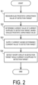
- FIG. 2 is a flowchart illustrating an example of a short circuit detection method performed by the short circuit detection device 100.
- the operation reception unit 220 outputs an operation signal to the processing unit 200.
- the processing unit 200 recognizes that the operation signal requests short circuit detection, the processing unit 200 starts short circuit detection.
- step S1 the processing unit 200 measures the electrostatic capacitance value C of the detection target 1.
- step S2 the processing unit 200 determines the current value I1 of the current I to be supplied to the detection target 1 on the basis of the electrostatic capacitance value C of the detection target 1.
- the processing unit 200 uses the electrostatic capacitance value C obtained in step S1 to calculate the current value I1 of the current I.
- step S3 the processing unit 200 supplies, to the detection target 1, the current I having the current value I1 to be supplied to the detection target 1.
- the processing unit 200 switches the switch unit 13 to connect the constant current source 11 to the positive electrode (+) of the detection target 1, and switches the switch unit 21 to connect the capacitance-measuring current measurement unit 22 to the negative electrode (-) of the detection target 1.
- the processing unit 200 controls the constant current source 11 such that the current I having the current value I1 obtained in step S2 flows through the detection target 1.
- step S4 the processing unit 200 detects a short circuit in the detection target 1 while the current I whose current value I1 is maintained constant is being supplied to the detection target 1.
- the short circuit detection device 100 includes the capacitance measurement power source 20 and the capacitance-measuring current measurement unit 22 (capacitance measurement means) that measure the electrostatic capacitance value C of the detection target 1, and the processing unit 200 (current determination means) that determines the current value I1 of the current I to be supplied to the detection target 1.
- the short circuit detection device 100 further includes the constant current source 11 (current supply means) that supplies the current I to the detection target 1, and the current measurement unit 130 and the fluctuation detection circuit 140 (detection means) that detect a short circuit in the detection target 1.
- the capacitance measurement power source 20 and the capacitance-measuring current measurement unit 22 measure the electrostatic capacitance value C of the detection target 1.
- the processing unit 200 determines the current value I1 of the current I to be supplied to the detection target 1, on the basis of the electrostatic capacitance value C measured by the capacitance measurement power source 20 and the capacitance-measuring current measurement unit 22 (capacitance measurement means).
- the constant current source 11 supplies the current I having the current value I1 determined by the processing unit 200 (current determination means) to the detection target 1. While the current I having the current value I1 is being supplied to the detection target 1 by the constant current source 11, the current measurement unit 130 and the fluctuation detection circuit 140 (detection means) detect a short circuit in the detection target 1.
- the short circuit detection device 100 before supplying the current I to the detection target 1, the short circuit detection device 100 can determine the current value I1 of the current I, on the basis of the electrostatic capacitance value C, by measuring the electrostatic capacitance value C of the detection target 1.
- a short circuit occurring in the detection target 1 can be detected without setting the current value I1 of the current I to be supplied to the detection target 1 for each detection target 1.
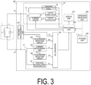
- FIG. 3 is a block diagram illustrating a modification of a configuration of the short circuit detection device 100 according to the first embodiment.
- the short circuit detection device 100 includes a storage unit 230.
- the storage unit 230 constitutes storage means in which a detection time T is stored in advance before the processing unit 200 determines the current value I1.
- the detection time T is a time during which the processing unit 200 detects a short circuit in the detection target 1.
- the operation reception unit 220 when the user uses the operation reception unit 220 to perform an input operation, the operation reception unit 220 outputs, to the processing unit 200, an operation signal corresponding to the input operation. Subsequently, the processing unit 200 determines whether the operation signal is a setting signal indicating the detection time T. In a case where the operation signal is determined to be the setting signal, the processing unit 200 stores the detection time T indicated by the setting signal in the storage unit 230.
- the detection time T is set to 5 milliseconds, for example.
- the processing unit 200 determines the current value I1 of the current I on the basis of the electrostatic capacitance value C and the detection time T stored in the storage unit 230.
- the short circuit detection device 100 includes the storage unit 230 (storage means).
- the storage unit 230 stores the detection time T, before the processing unit 200 (current determination means) determines the current value I1 of the current I to be supplied to the detection target 1.
- the processing unit 200 determines the current value I1 of the current I on the basis of the detection time T set in the storage unit 230 and the electrostatic capacitance value C measured by the capacitance measurement power source 20 and the capacitance-measuring current measurement unit 22 (capacitance measurement means).
- the short circuit detection device 100 supplies the current I having the current value I1 to the detection target 1 in consideration of not only the electrostatic capacitance value C of the detection target 1 but also the detection time T set in advance.
- the detection target 1 By determining the current value I1 in consideration of not only the electrostatic capacitance value C but also the detection time T, it is possible to supply the detection target 1 with the current I in an amount suitable for short circuit detection of the detection target 1 during the detection time T determined in advance. Therefore, it is possible to accurately detect a short circuit in the detection target 1 within a determined period of time.
- the short circuit detection device 100 similarly to the first modification, in addition to the configuration of the short circuit detection device 100 illustrated in FIG. 1 , the short circuit detection device 100 according to a second modification includes the storage unit 230.
- the storage unit 230 constitutes storage means in which a set current value Is is stored in advance, before the processing unit 200 determines the current value I1 of the current I.
- the set current value Is is a current value of the current I determined in accordance with the electric characteristics of the detection target 1.
- the set current value Is in the second modification is set to a current value of the current I suitable for detecting a short circuit occurring in the detection target 1.
- the operation reception unit 220 when the user uses the operation reception unit 220 to perform an input operation, the operation reception unit 220 outputs, to the processing unit 200, an operation signal corresponding to the input operation. Upon determining that the operation signal is a setting signal indicating the set current value Is, the processing unit 200 stores the set current value Is indicated by the setting signal in the storage unit 230.
- the processing unit 200 determines the current value I1 of the current I to be supplied to the detection target 1, on the basis of the electrostatic capacitance value C.
- the processing unit 200 determines whether the set current value Is stored in the storage unit 230 is equal to or less than the determined current value I1. When the set current value Is is equal to or less than the current value I1, the processing unit 200 detects a short circuit in the detection target 1 while the current I having the set current value Is is being supplied to the detection target 1.
- the processing unit 200 detects a short circuit in the detection target 1 while the current I having the determined current value I1 is being supplied to the detection target 1.
- the processing unit 200 detects a short circuit in the detection target 1 in accordance with the electrostatic capacitance value C.
- the short circuit detection device 100 in addition to the configuration of the short circuit detection device 100 illustrated in FIG. 1 , includes the storage unit 230 (storage means).
- the storage unit 230 stores the set current value Is set in advance, before the processing unit 200 (current determination means) determines the current value I1 of the current I to be supplied to the detection target 1.
- the processing unit 200 determines the current value I1 of the current I to be supplied to the detection target 1, on the basis of the electrostatic capacitance value C measured by the capacitance measurement power source 20 and the capacitance-measuring current measurement unit 22.
- the processing unit 200 detects a short circuit in the detection target 1 while the current I having the set current value Is is being supplied to the detection target 1.
- the current I that is a weak current equal to or less than the current value I1 to the detection target 1 it is possible to detect a short circuit in the detection target 1 by using the weak current I that matches the electric characteristics of the detection target 1 and by which the short circuit in the detection target 1 can be easily detected. Furthermore, it is possible to avoid supplying an excessive current to the detection target 1 and to suppress the consumption of power required in the short circuit detection process.
- the short circuit detection device 100 has the same configuration as that illustrated in FIG. 3 , but a specific function is added to the processing unit 200.
- the processing unit 200 increases the current value I1 of the current I supplied to the detection target 1 as the measured electrostatic capacitance value C of the detection target 1 increases, and decreases the current value I1 of the current I supplied to the detection target 1 as the electrostatic capacitance value C of the detection target 1 decreases.
- an electrostatic capacitance value set in advance in the storage unit 230 of the short circuit detection device 100 may be used, or the electrostatic capacitance value C at the last time a short circuit was detected may be used.
- a method of increasing or decreasing the current value I1 may include increasing or decreasing the magnitude of the current value I1 set in advance in the storage unit 230 of the short circuit detection device 100, or using the current value I1 determined on the basis of the detection time T or the electrostatic capacitance value C.
- the processing unit 200 (current determination means) in the third modification increases the current value I1 of the current I supplied to the detection target 1 as the electrostatic capacitance value C increases, and decreases the current value I1 of the current I supplied to the detection target 1 as the electrostatic capacitance value C decreases.
- the short circuit detection device 100 supplies the current I having a large current value I1.
- the electrostatic capacitance value C of the detection target 1 is small, the short circuit detection device 100 supplies the current I having a small current value I1.
- the current value I1 is adjusted in accordance with the electrostatic capacitance value C, so that the detection times for detecting a short circuit in the detection target 1 are similar to each other.
- the short circuit detection device 100 has the same configuration as that illustrated in FIG. 3 , but a specific function is added to the processing unit 200.
- the processing unit 200 controls the constant current source 11 such that a value obtained by dividing the electrostatic capacitance value C of the detection target 1 by the current value I1 of the current I supplied to the detection target 1 is constant.
- the processing unit 200 controls an operation of the constant current source 11 such that the current I having a value of 5 [mA] is supplied to the detection target 1 when an electrostatic capacitance value C1 is 10 [ ⁇ F], and the current I having a value of 10 [mA] is supplied to the detection target 1 when an electrostatic capacitance value C2 is 5 [ ⁇ F].
- the processing unit 200 controls the constant current source 11 (current supply means) such that a value obtained by dividing the electrostatic capacitance value C by the current value I1 of the current I supplied to the detection target 1 is constant.
- the short circuit detection device 100 can adjust the current such that a value obtained by dividing the electrostatic capacitance value C of the detection target 1 by the current value I1 of the current supplied to the detection target 1 is constant. As a result, the short circuit detection device 100 can detect a short circuit at the same detection time even if the electrostatic capacitance values C of the detection targets 1 differ from each other.
- the short circuit detection device 100 includes the storage unit 230.
- the storage unit 230 constitutes storage means that stores an upper limit current value Iu set in advance, before the processing unit 200 determines the current value I1 of the current I to be supplied to the detection target 1.
- the upper limit current value Iu is a current value indicating an upper limit of the current I that can be supplied to the detection target 1.
- the upper limit current value Iu is determined in advance on the basis of the electric characteristics of the detection target 1, so as not to supply an excessive current to the detection target 1.
- the upper limit current value Iu is set to several [A].
- the electrostatic capacitance value C of the detection target 1 is measured by the capacitance measurement power source 20 and the capacitance-measuring current measurement unit 22, and the processing unit 200 determines the current value I1 of the current I to be supplied to the detection target 1, on the basis of the measured electrostatic capacitance value C.
- the processing unit 200 determines whether the upper limit current value Iu stored in the storage unit 230 is equal to or greater than the determined current value I1. When the upper limit current value Iu is equal to or greater than the current value I1, the processing unit 200 detects a short circuit in the detection target 1 while the current I having the determined current value I1 is being supplied to the detection target 1.
- the processing unit 200 detects a short circuit in the detection target 1 while the current I having the upper limit current value Iu is being supplied to the detection target 1.
- the short circuit detection device 100 includes the storage unit 230 (storage means). Before the processing unit 200 (current determination means) determines the current value I1 of the current I to be supplied to the detection target 1, the upper limit current value Iu indicating an upper limit of the current I on the basis of the electric characteristics of the detection target 1 is stored in advance in the storage unit 230.
- the processing unit 200 determines the current value I1 of the current I to be supplied to the detection target 1, on the basis of the electrostatic capacitance value C measured by the capacitance measurement power source 20 and the capacitance-measuring current measurement unit 22 (capacitance measurement means). When the upper limit current value Iu is equal to or greater than the determined current value I1, the processing unit 200 (current determination means) detects a short circuit in the detection target 1 while the current I having the determined current value I1 is being supplied to the detection target 1.
- the short circuit detection device 100 sets the upper limit current value Iu in advance, and when the upper limit current value Iu is equal to or greater than the current value I1 determined on the basis of the electrostatic capacitance value C, supplies the current I having the determined current value I1 to the detection target 1.
- the short circuit detection device 100 limits the current I supplied to the detection target 1 to the upper limit current value Iu such that the current value I1 does not exceed the upper limit current value Iu.
- the detection time T, the set current value Is, or the upper limit current value Iu is set in the processing unit 200 by the operation reception unit 220 provided in the short circuit detection device 100.
- the present embodiment is not limited thereto.
- the remote controller may be used as the operation reception unit 220.
- the positive electrode (+) of the detection target 1 is connected to the connection terminal 101 of the short circuit detection device 100, and the negative electrode (-) of the detection target 1 is connected to the connection terminal 102 of the short circuit detection device 100.
- any electrode among the positive electrode (+) and the negative electrode (-) of the detection target 1 and an exterior casing constituting the detection target 1 may be respectively connected to the connection terminal 101 and the connection terminal 102 of the short circuit detection device 100.
- a constant current is supplied to the detection target 1 to detect a short circuit by using a voltage between the two electrodes of the detection target 1 or a current flowing through the detection target 1.
- the present embodiment is not limited thereto.
- Various methods can be used to detect a short circuit, such as a method of detecting a short circuit by measuring a voltage drop after the detection target 1 is charged, or a method of detecting a short circuit from a change in current when a voltage is applied to the detection target 1.
- the electrostatic capacitance value C of the detection target 1 is measured by applying an AC voltage to the detection target 1 and measuring a current flowing through the detection target 1.
- the present embodiment is not limited thereto.
- the electrostatic capacitance value C may be measured by measuring a current when the detection target 1 is being discharged, by a method using an impedance bridge or a dip meter, by an integration method, or by a method of measuring the electrostatic capacitance value C from a vector of a current flowing through the detection target 1.
- the electrostatic capacitance value C can be measured by using various methods.
Landscapes
- Physics & Mathematics (AREA)
- General Physics & Mathematics (AREA)
- Engineering & Computer Science (AREA)
- Manufacturing & Machinery (AREA)
- Power Engineering (AREA)
- Chemical & Material Sciences (AREA)
- Chemical Kinetics & Catalysis (AREA)
- Electrochemistry (AREA)
- General Chemical & Material Sciences (AREA)
- Testing Of Short-Circuits, Discontinuities, Leakage, Or Incorrect Line Connections (AREA)
Abstract
Description
- The present invention relates to a short circuit detection device and a short circuit detection method.
-
JP 2020-71054 A - An inspection device such as described above supplies a current to a detection target such as a lithium secondary battery. However, a current value of the current to be supplied to the detection target needs to be set for each detection target, on the basis of a rated current value of the detection target or the like.
- The present invention has been contrived in view of the problems mentioned above, and an object thereof is to provide a short circuit detection device and a short circuit detection method capable of detecting a short circuit occurring in a detection target, without setting, for each detection target, a current value of a current to be supplied to the detection target.
- According to an aspect of the present invention, a short circuit detection device for detecting a short circuit occurring in a detection target includes a capacitance measurement means configured to measure an electrostatic capacitance value of the detection target, and a current determination means configured to determine a current value of a current to be supplied to the detection target, on the basis of the electrostatic capacitance value measured by the capacitance measurement means. The short circuit detection device further includes a current supply means configured to supply the current having the current value determined by the current determination means to the detection target, and a detection means configured to detect a short circuit in the detection target while the current is being supplied to the detection target by the current supply means.
- According to this aspect, by measuring the electrostatic capacitance value of the detection target before supplying the current to the detection target, the current value of the current to be supplied to the detection target can be determined, on the basis of the electrostatic capacitance value. Therefore, it is possible to detect a short circuit without setting, for each detection target, the current value of the current to be supplied to the detection target.
-
-
FIG. 1 is a block diagram illustrating a functional configuration of a short circuit detection device according to a first embodiment of the present invention. -
FIG. 2 is a flowchart illustrating a processing procedure of a short circuit detection method according to the first embodiment. -
FIG. 3 is a block diagram illustrating a modification of the short circuit detection device according to the first embodiment. - Embodiments of the present invention will be described below with reference to the accompanying drawings.
-
FIG. 1 is a block diagram illustrating a functional configuration of a shortcircuit detection device 100 according to a first embodiment. - The short
circuit detection device 100 detects a short circuit occurring in a detection target 1. Here, the term "short circuit" includes not only a steady short circuit but also a short-time short circuit such as short-time insulation failure and insulation deterioration caused by an abnormal situation occurring in the detection target 1. - Examples of factors causing a short-time short circuit include anomalies such as a foreign metal substance being present in an electrode constituting a battery, occurrence of contamination, burr between an electrode of a battery and an exterior casing of the battery, cracks in a laminated ceramic capacitor, and micro-short circuits between substrate patterns.
- As described above, the short
circuit detection device 100 detects a short circuit caused by the above-mentioned anomaly occurring in the detection target 1. For example, the shortcircuit detection device 100 is used to measure or examine the detection target 1 in which a DC electric signal is supplied (applied) to the detection target 1. - The short
circuit detection device 100 according to the first embodiment supplies a DC voltage to the detection target 1 to measure an insulation resistance value R of the detection target 1, on the basis of the magnitude of a leakage current output from a negative electrode (-) of the detection target 1. - The detection target 1 is an object having at least capacitance of an electrostatic capacitance value C and, in a state in which a DC electric signal is supplied to the object, a voltage signal generated in the object or a current signal flowing through the object temporarily fluctuates when an anomaly occurs in the object.
- Hereinafter, a state where the level of the electric signal increases from a standard level and then decreases is referred to as a "temporary increase", and a state where the level of the electric signal decreases from the standard level and then increases is referred to as a "temporary decrease". These temporary fluctuations are also simply referred to as "fluctuations".
- An example of the detection target 1 is a secondary battery. The secondary battery is a chargeable and dischargeable storage battery, and is a power storage device including a capacitor-type power storage element such as an electric double-layer capacitor. The secondary battery may be a unit cell or may be a battery pack in which a plurality of unit cells are connected in parallel, in series, or in series-parallel.
- Examples of the secondary battery include a lead storage battery, a nickel-hydrogen battery, a nickel-cadmium battery, a lithium metal battery, a lithium ion battery, a lithium ion polymer battery, an all-solid-state lithium ion battery, and a sodium ion battery. In addition, an aqueous solution-type electric double-layer capacitor or a drainage solution-type electric double-layer capacitor can also be used as the secondary battery.
- The detection target 1 in the first embodiment is a lithium ion battery before liquid injection. The lithium ion battery has the insulation resistance value R and the electrostatic capacitance value C, and is represented by an equivalent circuit in which the insulation resistance value R and the electrostatic capacitance value C are connected in parallel to each other.
- In the first embodiment, a positive electrode (+) of the detection target 1 is connected to a
connection terminal 101 of the shortcircuit detection device 100, and the negative electrode (-) of the detection target 1 is connected to aconnection terminal 102 of the shortcircuit detection device 100. - The short
circuit detection device 100 includes acurrent limiter 10, a constantcurrent source 11, aconstant voltage source 12, aswitch unit 13, a capacitancemeasurement power source 20, aswitch unit 21, a capacitance-measuringcurrent measurement unit 22, avoltage measurement unit 120, acurrent measurement unit 130, afluctuation detection circuit 140, and anAD converter 150. The shortcircuit detection device 100 further includes aprocessing unit 200, adisplay unit 210, anoperation reception unit 220, and afluctuation detection circuit 240. - The
current limiter 10 is connected to an output terminal of theconstant voltage source 12. Thecurrent limiter 10 limits a current supplied from theconstant voltage source 12 to the detection target 1, in accordance with an instruction from theprocessing unit 200. - The constant
current source 11 constitutes constant current supply means that supplies, to the detection target 1, a current I that is controlled such that a predetermined current value is maintained. Hereinafter, the predetermined current value is denoted by I1. The constantcurrent source 11 charges the detection target 1 by supplying a constant direct current to the positive electrode (+) of the detection target 1 via theconnection terminal 101 of the shortcircuit detection device 100. - The
constant voltage source 12 constitutes constant voltage supply means that supplies, to the detection target 1, a voltage V that is controlled such that a predetermined voltage value is maintained. Hereinafter, the predetermined voltage value is denoted by V1. Theconstant voltage source 12 supplies a constant DC voltage between the positive electrode and the negative electrode of the detection target 1 via theconnection terminal 101 to detect a leakage current of the detection target 1. - The
switch unit 13 switches the power source connectable to the detection target 1 between the capacitancemeasurement power source 20, the constantcurrent source 11, and theconstant voltage source 12. Theswitch unit 13 connects the positive electrode (+) of the detection target 1 and the capacitancemeasurement power source 20 in accordance with a command from theprocessing unit 200 and, when measurement of the electrostatic capacitance value of the detection target 1 is complete, switches the power source connected to the detection target 1 from the capacitancemeasurement power source 20 to the constantcurrent source 11 or theconstant voltage source 12. - The capacitance
measurement power source 20 constitutes current supply means that supplies a capacitance measurement voltage to the detection target 1. The capacitancemeasurement power source 20 charges and discharges the detection target 1 by supplying an AC voltage as the capacitance measurement voltage to the positive electrode (+) of the detection target 1 via theconnection terminal 101 of the shortcircuit detection device 100. The capacitance measurement voltage is an AC voltage having a plurality of frequency components. - The
switch unit 21 switches the current measurement unit connected to the detection target 1 between thecurrent measurement unit 130 and the capacitance-measuringcurrent measurement unit 22. Theswitch unit 21 connects the negative electrode (-) of the detection target 1 and the capacitance-measuringcurrent measurement unit 22 in accordance with a command of theprocessing unit 200 and, when measurement of the electrostatic capacitance value C of the detection target 1 is complete, switches the capacitance-measuringcurrent measurement unit 22 connected to the detection target 1 to thecurrent measurement unit 130. - The capacitance-measuring
current measurement unit 22 executes a current measurement process for measuring the electrostatic capacitance value C of the detection target 1 in accordance with a capacitance measurement command from theprocessing unit 200. - The capacitance-measuring
current measurement unit 22 measures an alternating current of the detection target 1 on the basis of a response signal generated in the detection target 1 while an AC signal is being supplied between the positive electrode (+) and the negative electrode (-) of the detection target 1. The capacitance-measuringcurrent measurement unit 22 outputs, to theAD converter 150, a voltage signal indicating the magnitude of the measured alternating current, as a current detection signal Vci. - The
current measurement unit 130 constitutes measurement means that measures the magnitude of the current generated in the detection target 1. Thecurrent measurement unit 130 acquires a current detection signal Vi indicating a current value of the detection target 1. - The
current measurement unit 130 according to the first embodiment measures the magnitude of the leakage current output from the negative electrode (-) of the detection target 1. Subsequently, thecurrent measurement unit 130 outputs, to theAD converter 150, a voltage signal indicating the magnitude of the measured current, as the current detection signal Vi. - For example, in a state where the detection target 1 is being charged by the constant
current source 11, the magnitude of the leakage current is at the milliampere (mA) level. On the other hand, in a state where the voltage of the detection target 1 is maintained at the voltage value V1 by theconstant voltage source 12, the magnitude of the leakage current is at the nanoampere (nA) or microampere (µA) level. - For example, the
current measurement unit 130 is constituted by an IV conversion circuit that converts an input current into a voltage. Thecurrent measurement unit 130 generates a measurement signal Vmi indicating the magnitude of the current output from the negative electrode (-) of the detection target 1, and outputs the generated measurement signal Vmi to thefluctuation detection circuit 140. - The
fluctuation detection circuit 140 detects a fluctuation of the measurement signal Vmi caused by a short circuit occurring in the detection target 1. Thefluctuation detection circuit 140 according to the first embodiment detects a temporary fluctuation of the measurement signal Vmi caused by a short circuit occurring when a foreign substance enters the detection target 1. - For example, the
fluctuation detection circuit 140 is constituted by a comparator circuit. Thefluctuation detection circuit 140 outputs a fluctuation detection signal Vdi indicating the detected fluctuation to theAD converter 150. - The
fluctuation detection circuit 240 detects a fluctuation of a measurement signal Vmv caused by a short circuit occurring in the detection target 1. Thefluctuation detection circuit 240 according to the first embodiment detects a temporary fluctuation of the measurement signal Vmv caused by a short circuit occurring when a foreign substance enters the detection target 1. - The
fluctuation detection circuit 240 has a configuration identical or equivalent to that of thefluctuation detection circuit 140. For example, thefluctuation detection circuit 240 is constituted by a comparator circuit. Thefluctuation detection circuit 240 outputs a fluctuation detection signal Vdv indicating the detected fluctuation to theAD converter 150. - The
AD converter 150 samples the current detection signal Vci from the capacitance-measuringcurrent measurement unit 22 at a predetermined period, and outputs data generated by the sampling to theprocessing unit 200. - Similarly, the
AD converter 150 samples the current detection signal Vi from thecurrent measurement unit 130, the fluctuation detection signal Vdi from thefluctuation detection circuit 140, a voltage detection signal Vv from thevoltage measurement unit 120, and the fluctuation detection signal Vdv from thefluctuation detection circuit 240 at a predetermined period. Subsequently, theAD converter 150 outputs each piece of data generated by the sampling to theprocessing unit 200. - The
processing unit 200 is a computer including a processor, a read only memory (ROM), a random access memory (RAM), a mass storage device, an input/output interface, and a bus connecting these components to each other. Examples of the processor include a central processing unit (CPU) and a micro processor unit (MPU). Examples of the mass storage device include a hard disk drive (HDD) and a solid state drive (SSD). - The
processing unit 200 controls thecurrent limiter 10, the constantcurrent source 11, and theconstant voltage source 12, which constitute apower source unit 110, and controls theswitch unit 13, the capacitancemeasurement power source 20, and theswitch unit 21. - The
processing unit 200 executes a short circuit detection process for detecting a short circuit occurring in the detection target 1. For example, upon receiving, from theoperation reception unit 220, a request signal requesting execution of the short circuit detection process, theprocessing unit 200 executes the short circuit detection process. - In the above-described short circuit detection process, first, the
processing unit 200 controls the connection of theswitch unit 13 so as to connect the capacitancemeasurement power source 20 to the positive electrode (+) of the detection target 1. Subsequently, theprocessing unit 200 controls the capacitancemeasurement power source 20 to supply an AC voltage having a plurality of frequency components to the detection target 1. - The
processing unit 200 controls theswitch unit 21 to connect the capacitance-measuringcurrent measurement unit 22 to the negative electrode (-) of the detection target 1. Subsequently, theprocessing unit 200 controls the capacitance-measuringcurrent measurement unit 22 to measure the current value of the current flowing through the detection target 1 by the AC voltage supplied by the capacitancemeasurement power source 20. - The
processing unit 200 acquires the current detection signal Vci indicating a current value of the detection target 1 from the capacitance-measuringcurrent measurement unit 22 via theAD converter 150. Subsequently, theprocessing unit 200 measures the electrostatic capacitance value C of the detection target 1 on the basis of the current detection signal Vci. As described above, theprocessing unit 200 measures the electrostatic capacitance value C by using an AC impedance measurement method. - After measuring the electrostatic capacitance value C, the
processing unit 200 uses the measured electrostatic capacitance value C of the detection target 1 to determine the current value I1 of the current I output from the constantcurrent source 11. That is, theprocessing unit 200 constitutes current determination means that determines, on the basis of the measured electrostatic capacitance value C, the current value I1 of the current I to be supplied to the detection target 1. - While the current I having the current value I1 is being supplied to a capacitor having the electrostatic capacitance value C in the detection target 1, a voltage Vf between the two ends of the capacitor at which the capacitor is fully charged is represented by the current value I1, the electrostatic capacitance value C, and a charging time Tc required for complete charging, as illustrated in Equation (1) below.

- For example, if the current value I1 of the current I supplied to the detection target 1 is a fixed value, regardless of the detection target 1, the charging time Tc varies depending on the difference in the electrostatic capacitance value C of each detection target 1. Depending on the electrostatic capacitance value C, the current value I1 may need to be reduced so as not to damage the detection target 1. Therefore, it is necessary to set the current value I1 for each detection target 1 in accordance with the electric characteristics of the detection target 1.
- As a countermeasure, the
processing unit 200 according to the first embodiment determines the current value I1 of the current I on the basis of the measured electrostatic capacitance value C of the detection target 1. - Next, the
processing unit 200 controls operations of the constantcurrent source 11 and theconstant voltage source 12 on the basis of the voltage detection signal Vv and the current detection signal Vi. - Specifically, after determining the current value I1 of the current I supplied to the detection target 1, the
processing unit 200 acquires the voltage detection signal Vv indicating the voltage value of the detection target 1 via theAD converter 150. - Subsequently, the
processing unit 200 controls the connection of theswitch unit 13 to connect the constantcurrent source 11 to the positive electrode (+) of the detection target 1. Then, theprocessing unit 200 controls the constantcurrent source 11 on the basis of the current detection signal Vi such that the current value I1 of the current I used by the constantcurrent source 11 to charge the detection target 1 is maintained at a constant value. - At this time, the
processing unit 200 determines, on the basis of the voltage detection signal Vv, whether the voltage generated between the positive electrode (+) and the negative electrode (-) of the detection target 1 reaches the predetermined voltage value V1. - In a case where the voltage of the detection target 1 reaches the voltage value V1, the
processing unit 200 controls the connection of theswitch unit 13 to switch the power source connected to the detection target 1 from the constantcurrent source 11 to theconstant voltage source 12. Subsequently, theprocessing unit 200 controls theconstant voltage source 12 on the basis of the voltage detection signal Vv, such that the voltage value V1 of the voltage generated between the two electrodes of the detection target 1 is maintained at a constant value. That is, theprocessing unit 200 according to the first embodiment uses theconstant voltage source 12 to perform constant voltage control. - As described above, upon receiving the request signal mentioned above, the
processing unit 200 controls an operation of thepower source unit 110, such that the detection target 1 is charged with the current I maintained at the current value I1 and the voltage value V1 is continuously supplied to the detection target 1. - While power is being supplied from the
power source unit 110 to the detection target 1, theprocessing unit 200 acquires the fluctuation detection signal Vdi or the fluctuation detection signal Vdv via theAD converter 150. Subsequently, theprocessing unit 200 determines, on the basis of the fluctuation detection signal Vdi or the fluctuation detection signal Vdv, whether a short circuit has occurred due to an abnormal situation that may occur in the detection target 1. - The
processing unit 200 calculates a physical quantity of the detection target 1 on the basis of the current detection signal Vi and the voltage detection signal Vv acquired via theAD converter 150. Examples of the physical quantity of the detection target 1 include a leakage current value of the detection target 1 and the insulation resistance value R of the detection target 1. Theprocessing unit 200 outputs, to thedisplay unit 210, a determination result or a calculation result indicating whether there is a short circuit. - The
display unit 210 generates image data expressing the determination result or the calculation result output from theprocessing unit 200 and displays the image data. For example, thedisplay unit 210 is constituted by an LED display, a liquid crystal panel, or a touch panel. - The
operation reception unit 220 receives an input operation by a user and outputs an operation signal indicating the received input operation to theprocessing unit 200. For example, theoperation reception unit 220 is constituted by a push button provided in the vicinity of a screen of thedisplay unit 210, a touch sensor incorporated in a touch panel, or a keyboard and a mouse. - For example, the
operation reception unit 220 receives a user operation in which the user depresses a button for executing the short circuit detection process, and in response to reception of the user operation, outputs the above-described short circuit detection request to theprocessing unit 200. Thus, the short circuit detection process is executed in the shortcircuit detection device 100. - Next, an operation of the short
circuit detection device 100 according to the first embodiment will be described. - First, in the short
circuit detection device 100, for example, when a user uses theoperation reception unit 220 to perform an input operation, theoperation reception unit 220 outputs an operation signal to theprocessing unit 200. Subsequently, when theprocessing unit 200 recognizes that the operation signal is a request signal for the short circuit detection process, theprocessing unit 200 starts the short circuit detection process. - First, the
processing unit 200 measures the electrostatic capacitance value C of the detection target 1. - Specifically, the
processing unit 200 switches theswitch unit 13 to connect the capacitancemeasurement power source 20 to the positive electrode (+) of the detection target 1, and switches theswitch unit 21 to connect the capacitance-measuringcurrent measurement unit 22 to the negative electrode (-) of the detection target 1. Subsequently, theprocessing unit 200 controls the capacitancemeasurement power source 20 to supply a capacitance measurement voltage to the detection target 1. - In this state, the capacitance-measuring
current measurement unit 22 measures an alternating current flowing through the detection target 1 and outputs, to theAD converter 150, the current detection signal Vci indicating the magnitude of the alternating current flowing through the detection target 1. TheAD converter 150 outputs data indicating the magnitude of the current detection signal Vci to theprocessing unit 200. Theprocessing unit 200 calculates the electrostatic capacitance value C of the detection target 1 on the basis of the current detection signal Vci. - Subsequently, on the basis of the calculated electrostatic capacitance value C, the
processing unit 200 determines the current value I1 of the current I to be supplied to the detection target 1. In a specific example, theprocessing unit 200 uses the electrostatic capacitance value C of the detection target 1 to calculate the current value I1 of the current I to be supplied. For example, a value obtained by calculating k · C is used as the current value I1, where k is an appropriately determined coefficient. In another example, a value obtained by calculating Va · C/Tc is used as the current value I1, where Va is the voltage when the detection target 1 is fully charged and Tc is the charging time. Subsequently, on the basis of the determined current value I1, theprocessing unit 200 supplies, to the detection target 1, the current I indicating the current value I1. - Then, the
processing unit 200 switches theswitch unit 13 to connect the positive electrode (+) of the detection target 1 and the constantcurrent source 11, and switches theswitch unit 21 to connect the negative electrode (-) of the detection target 1 and thecurrent measurement unit 130. Theprocessing unit 200 controls the constantcurrent source 11 such that the current I having the current value I1 flows through the detection target 1. - In a state where the constant
current source 11 supplies the current I having the current value I1, theprocessing unit 200 detects a short circuit in the detection target 1. - Specifically, the
current measurement unit 130 outputs, to thefluctuation detection circuit 140, the measurement signal Vmi indicating the magnitude of the current flowing through the detection target 1. On the basis of the measurement signal Vmi, thefluctuation detection circuit 140 outputs, to theAD converter 150, the fluctuation detection signal Vdi indicating whether a short circuit is occurring in the detection target 1. TheAD converter 150 outputs data obtained by sampling the fluctuation detection signal Vdi to theprocessing unit 200. Theprocessing unit 200 detects a short circuit occurring in the detection target 1 from the data indicating the fluctuation detection signal Vdi. - Note that, in the first embodiment, the
processing unit 200 detects the short circuit in the detection target 1 by using the fluctuation detection signal Vdi of thefluctuation detection circuit 140. However, theprocessing unit 200 may detect the short circuit in the detection target 1 by using the fluctuation detection signal Vdv of thefluctuation detection circuit 240. - Next, a short circuit detection method according to the first embodiment will be described with reference to
FIG. 2 . -
FIG. 2 is a flowchart illustrating an example of a short circuit detection method performed by the shortcircuit detection device 100. - First, in the short
circuit detection device 100, for example, when a user uses theoperation reception unit 220 to perform an input operation, theoperation reception unit 220 outputs an operation signal to theprocessing unit 200. When theprocessing unit 200 recognizes that the operation signal requests short circuit detection, theprocessing unit 200 starts short circuit detection. - In step S1, the
processing unit 200 measures the electrostatic capacitance value C of the detection target 1. - In step S2, the
processing unit 200 determines the current value I1 of the current I to be supplied to the detection target 1 on the basis of the electrostatic capacitance value C of the detection target 1. Theprocessing unit 200 uses the electrostatic capacitance value C obtained in step S1 to calculate the current value I1 of the current I. - In step S3, the
processing unit 200 supplies, to the detection target 1, the current I having the current value I1 to be supplied to the detection target 1. - Specifically, the
processing unit 200 switches theswitch unit 13 to connect the constantcurrent source 11 to the positive electrode (+) of the detection target 1, and switches theswitch unit 21 to connect the capacitance-measuringcurrent measurement unit 22 to the negative electrode (-) of the detection target 1. Theprocessing unit 200 controls the constantcurrent source 11 such that the current I having the current value I1 obtained in step S2 flows through the detection target 1. - In step S4, the
processing unit 200 detects a short circuit in the detection target 1 while the current I whose current value I1 is maintained constant is being supplied to the detection target 1. - Next, operation and effects of the first embodiment will be described.
- The short
circuit detection device 100 according to the first embodiment includes the capacitancemeasurement power source 20 and the capacitance-measuring current measurement unit 22 (capacitance measurement means) that measure the electrostatic capacitance value C of the detection target 1, and the processing unit 200 (current determination means) that determines the current value I1 of the current I to be supplied to the detection target 1. The shortcircuit detection device 100 further includes the constant current source 11 (current supply means) that supplies the current I to the detection target 1, and thecurrent measurement unit 130 and the fluctuation detection circuit 140 (detection means) that detect a short circuit in the detection target 1. - The capacitance
measurement power source 20 and the capacitance-measuringcurrent measurement unit 22 measure the electrostatic capacitance value C of the detection target 1. The processing unit 200 (current determination means) determines the current value I1 of the current I to be supplied to the detection target 1, on the basis of the electrostatic capacitance value C measured by the capacitancemeasurement power source 20 and the capacitance-measuring current measurement unit 22 (capacitance measurement means). - The constant
current source 11 supplies the current I having the current value I1 determined by the processing unit 200 (current determination means) to the detection target 1. While the current I having the current value I1 is being supplied to the detection target 1 by the constantcurrent source 11, thecurrent measurement unit 130 and the fluctuation detection circuit 140 (detection means) detect a short circuit in the detection target 1. - According to this configuration, before supplying the current I to the detection target 1, the short
circuit detection device 100 can determine the current value I1 of the current I, on the basis of the electrostatic capacitance value C, by measuring the electrostatic capacitance value C of the detection target 1. Thus, a short circuit occurring in the detection target 1 can be detected without setting the current value I1 of the current I to be supplied to the detection target 1 for each detection target 1. - Below, modifications of the short
circuit detection device 100 according to the first embodiment will be described. These modifications are partial modifications of the first embodiment, and thus, description of components that are the same as those in the first embodiment will be omitted. -
FIG. 3 is a block diagram illustrating a modification of a configuration of the shortcircuit detection device 100 according to the first embodiment. - In addition to the configuration of the short
circuit detection device 100 illustrated inFIG. 1 , the shortcircuit detection device 100 according to a first modification includes astorage unit 230. - The
storage unit 230 constitutes storage means in which a detection time T is stored in advance before theprocessing unit 200 determines the current value I1. The detection time T is a time during which theprocessing unit 200 detects a short circuit in the detection target 1. - In a specific example, when the user uses the
operation reception unit 220 to perform an input operation, theoperation reception unit 220 outputs, to theprocessing unit 200, an operation signal corresponding to the input operation. Subsequently, theprocessing unit 200 determines whether the operation signal is a setting signal indicating the detection time T. In a case where the operation signal is determined to be the setting signal, theprocessing unit 200 stores the detection time T indicated by the setting signal in thestorage unit 230. The detection time T is set to 5 milliseconds, for example. - Subsequently, when the electrostatic capacitance value C of the detection target 1 is measured by the capacitance
measurement power source 20 and the capacitance-measuringcurrent measurement unit 22, theprocessing unit 200 determines the current value I1 of the current I on the basis of the electrostatic capacitance value C and the detection time T stored in thestorage unit 230. - Next, operation and effects of the first modification will be described.
- In addition to the configuration of the short
circuit detection device 100 illustrated inFIG. 1 , the shortcircuit detection device 100 according to the first modification includes the storage unit 230 (storage means). Thestorage unit 230 stores the detection time T, before the processing unit 200 (current determination means) determines the current value I1 of the current I to be supplied to the detection target 1. - The processing unit 200 (current determination means) determines the current value I1 of the current I on the basis of the detection time T set in the
storage unit 230 and the electrostatic capacitance value C measured by the capacitancemeasurement power source 20 and the capacitance-measuring current measurement unit 22 (capacitance measurement means). - According to this configuration, the short
circuit detection device 100 supplies the current I having the current value I1 to the detection target 1 in consideration of not only the electrostatic capacitance value C of the detection target 1 but also the detection time T set in advance. By determining the current value I1 in consideration of not only the electrostatic capacitance value C but also the detection time T, it is possible to supply the detection target 1 with the current I in an amount suitable for short circuit detection of the detection target 1 during the detection time T determined in advance. Therefore, it is possible to accurately detect a short circuit in the detection target 1 within a determined period of time. - As illustrated in
FIG. 3 , similarly to the first modification, in addition to the configuration of the shortcircuit detection device 100 illustrated inFIG. 1 , the shortcircuit detection device 100 according to a second modification includes thestorage unit 230. - The
storage unit 230 constitutes storage means in which a set current value Is is stored in advance, before theprocessing unit 200 determines the current value I1 of the current I. The set current value Is is a current value of the current I determined in accordance with the electric characteristics of the detection target 1. The set current value Is in the second modification is set to a current value of the current I suitable for detecting a short circuit occurring in the detection target 1. - In a specific example, when the user uses the
operation reception unit 220 to perform an input operation, theoperation reception unit 220 outputs, to theprocessing unit 200, an operation signal corresponding to the input operation. Upon determining that the operation signal is a setting signal indicating the set current value Is, theprocessing unit 200 stores the set current value Is indicated by the setting signal in thestorage unit 230. - Then, when the electrostatic capacitance value C of the detection target 1 is measured by the capacitance
measurement power source 20 and the capacitance-measuringcurrent measurement unit 22, theprocessing unit 200 determines the current value I1 of the current I to be supplied to the detection target 1, on the basis of the electrostatic capacitance value C. - The
processing unit 200 determines whether the set current value Is stored in thestorage unit 230 is equal to or less than the determined current value I1. When the set current value Is is equal to or less than the current value I1, theprocessing unit 200 detects a short circuit in the detection target 1 while the current I having the set current value Is is being supplied to the detection target 1. - On the other hand, when the set current value Is exceeds the current value I1, the
processing unit 200 detects a short circuit in the detection target 1 while the current I having the determined current value I1 is being supplied to the detection target 1. Thus, it is possible to detect a short circuit in the detection target 1 in accordance with the electrostatic capacitance value C. - Next, operation and effects of the second modification will be described.
- Similarly to the first modification, in addition to the configuration of the short
circuit detection device 100 illustrated inFIG. 1 , the shortcircuit detection device 100 according to the second modification includes the storage unit 230 (storage means). Thestorage unit 230 stores the set current value Is set in advance, before the processing unit 200 (current determination means) determines the current value I1 of the current I to be supplied to the detection target 1. - Subsequently, the processing unit 200 (current determination means) determines the current value I1 of the current I to be supplied to the detection target 1, on the basis of the electrostatic capacitance value C measured by the capacitance
measurement power source 20 and the capacitance-measuringcurrent measurement unit 22. When the set current value Is stored in thestorage unit 230 is equal to or less than the determined current value I1, theprocessing unit 200 detects a short circuit in the detection target 1 while the current I having the set current value Is is being supplied to the detection target 1. - According to this configuration, when the current value I1 determined on the basis of the electrostatic capacitance value C is greater than the set current value Is, the current I having the set current value Is is supplied to the detection target 1.
- As described above, by supplying, on the basis of the electrostatic capacitance value C, the current I that is a weak current equal to or less than the current value I1 to the detection target 1, it is possible to detect a short circuit in the detection target 1 by using the weak current I that matches the electric characteristics of the detection target 1 and by which the short circuit in the detection target 1 can be easily detected. Furthermore, it is possible to avoid supplying an excessive current to the detection target 1 and to suppress the consumption of power required in the short circuit detection process.
- The short
circuit detection device 100 according to a third modification has the same configuration as that illustrated inFIG. 3 , but a specific function is added to theprocessing unit 200. - Specifically, the
processing unit 200 increases the current value I1 of the current I supplied to the detection target 1 as the measured electrostatic capacitance value C of the detection target 1 increases, and decreases the current value I1 of the current I supplied to the detection target 1 as the electrostatic capacitance value C of the detection target 1 decreases. - In this process, as a comparison target for the magnitude of the electrostatic capacitance value C, an electrostatic capacitance value set in advance in the
storage unit 230 of the shortcircuit detection device 100 may be used, or the electrostatic capacitance value C at the last time a short circuit was detected may be used. - A method of increasing or decreasing the current value I1 may include increasing or decreasing the magnitude of the current value I1 set in advance in the
storage unit 230 of the shortcircuit detection device 100, or using the current value I1 determined on the basis of the detection time T or the electrostatic capacitance value C. - Next, operation and effects of the third modification will be described.
- The processing unit 200 (current determination means) in the third modification increases the current value I1 of the current I supplied to the detection target 1 as the electrostatic capacitance value C increases, and decreases the current value I1 of the current I supplied to the detection target 1 as the electrostatic capacitance value C decreases.
- According to this configuration, when the electrostatic capacitance value C of the capacitor constituting the detection target 1 is relatively large, the time required to charge the detection target 1 is long, and the short
circuit detection device 100 supplies the current I having a large current value I1. On the other hand, when the electrostatic capacitance value C of the detection target 1 is small, the shortcircuit detection device 100 supplies the current I having a small current value I1. - Thus, even if the electrostatic capacitance values C of individual detection targets 1 differ from each other, the current value I1 is adjusted in accordance with the electrostatic capacitance value C, so that the detection times for detecting a short circuit in the detection target 1 are similar to each other.
- The short
circuit detection device 100 according to a fourth modification has the same configuration as that illustrated inFIG. 3 , but a specific function is added to theprocessing unit 200. - Specifically, the
processing unit 200 controls the constantcurrent source 11 such that a value obtained by dividing the electrostatic capacitance value C of the detection target 1 by the current value I1 of the current I supplied to the detection target 1 is constant. - For example, the
processing unit 200 controls an operation of the constantcurrent source 11 such that the current I having a value of 5 [mA] is supplied to the detection target 1 when an electrostatic capacitance value C1 is 10 [µF], and the current I having a value of 10 [mA] is supplied to the detection target 1 when an electrostatic capacitance value C2 is 5 [µF]. - Next, operation and effects of the fourth modification will be described.
- The processing unit 200 (current determination means) in the fourth modification controls the constant current source 11 (current supply means) such that a value obtained by dividing the electrostatic capacitance value C by the current value I1 of the current I supplied to the detection target 1 is constant.
- In the detection target 1, when a current having the current value I1 is supplied to a capacitor having the electrostatic capacitance value C, the voltage V between the two ends of the capacitor after a time t in seconds is expressed by Equation (2) below. When this equation is rearranged to express the time t, Equation (3) below is obtained.


- Thus, the short
circuit detection device 100 can adjust the current such that a value obtained by dividing the electrostatic capacitance value C of the detection target 1 by the current value I1 of the current supplied to the detection target 1 is constant. As a result, the shortcircuit detection device 100 can detect a short circuit at the same detection time even if the electrostatic capacitance values C of the detection targets 1 differ from each other. - As illustrated in
FIG. 3 , similarly to the above-described modifications, in addition to the configuration of the shortcircuit detection device 100 illustrated inFIG. 1 , the shortcircuit detection device 100 according to a fifth modification includes thestorage unit 230. - The
storage unit 230 constitutes storage means that stores an upper limit current value Iu set in advance, before theprocessing unit 200 determines the current value I1 of the current I to be supplied to the detection target 1. - The upper limit current value Iu is a current value indicating an upper limit of the current I that can be supplied to the detection target 1. The upper limit current value Iu is determined in advance on the basis of the electric characteristics of the detection target 1, so as not to supply an excessive current to the detection target 1. For example, the upper limit current value Iu is set to several [A].
- Subsequently, the electrostatic capacitance value C of the detection target 1 is measured by the capacitance
measurement power source 20 and the capacitance-measuringcurrent measurement unit 22, and theprocessing unit 200 determines the current value I1 of the current I to be supplied to the detection target 1, on the basis of the measured electrostatic capacitance value C. - The
processing unit 200 determines whether the upper limit current value Iu stored in thestorage unit 230 is equal to or greater than the determined current value I1. When the upper limit current value Iu is equal to or greater than the current value I1, theprocessing unit 200 detects a short circuit in the detection target 1 while the current I having the determined current value I1 is being supplied to the detection target 1. - On the other hand, when the upper limit current value Iu is lower than the current value I1, the
processing unit 200 detects a short circuit in the detection target 1 while the current I having the upper limit current value Iu is being supplied to the detection target 1. - Next, operation and effects of the fifth modification will be described.
- In addition to the configuration of the short
circuit detection device 100 illustrated inFIG. 1 , the shortcircuit detection device 100 according to the fifth modification includes the storage unit 230 (storage means). Before the processing unit 200 (current determination means) determines the current value I1 of the current I to be supplied to the detection target 1, the upper limit current value Iu indicating an upper limit of the current I on the basis of the electric characteristics of the detection target 1 is stored in advance in thestorage unit 230. - The processing unit 200 (current determination means) determines the current value I1 of the current I to be supplied to the detection target 1, on the basis of the electrostatic capacitance value C measured by the capacitance
measurement power source 20 and the capacitance-measuring current measurement unit 22 (capacitance measurement means). When the upper limit current value Iu is equal to or greater than the determined current value I1, the processing unit 200 (current determination means) detects a short circuit in the detection target 1 while the current I having the determined current value I1 is being supplied to the detection target 1. - According to this configuration, the short
circuit detection device 100 sets the upper limit current value Iu in advance, and when the upper limit current value Iu is equal to or greater than the current value I1 determined on the basis of the electrostatic capacitance value C, supplies the current I having the determined current value I1 to the detection target 1. On the other hand, when the upper limit current value Iu is lower than the current value I1 determined on the basis of the electrostatic capacitance value C, the shortcircuit detection device 100 limits the current I supplied to the detection target 1 to the upper limit current value Iu such that the current value I1 does not exceed the upper limit current value Iu. - With this configuration, since the current value of the current I is adjusted such that no excessive current flows in the detection target 1, it is possible to detect a short circuit in the detection target 1 while avoiding a situation where the detection target 1 is burned or broken.
- The embodiments of the present invention described above merely illustrate a portion of the application examples of the present invention, and the technical scope of the present invention is not intended to be limited to the specific configurations of the embodiments described above.
- In the above-described embodiments, the detection time T, the set current value Is, or the upper limit current value Iu is set in the
processing unit 200 by theoperation reception unit 220 provided in the shortcircuit detection device 100. However, the present embodiment is not limited thereto. For example, in a case where the detection time T, the set current value Is, or the upper limit current value Iu can be set in theprocessing unit 200 through wired communication or radio communication by a remote controller that is different from the shortcircuit detection device 100, the remote controller may be used as theoperation reception unit 220. - In the above-described embodiments, the positive electrode (+) of the detection target 1 is connected to the
connection terminal 101 of the shortcircuit detection device 100, and the negative electrode (-) of the detection target 1 is connected to theconnection terminal 102 of the shortcircuit detection device 100. However, any electrode among the positive electrode (+) and the negative electrode (-) of the detection target 1 and an exterior casing constituting the detection target 1 may be respectively connected to theconnection terminal 101 and theconnection terminal 102 of the shortcircuit detection device 100. - In the above-described embodiments, a constant current is supplied to the detection target 1 to detect a short circuit by using a voltage between the two electrodes of the detection target 1 or a current flowing through the detection target 1. However, the present embodiment is not limited thereto. Various methods can be used to detect a short circuit, such as a method of detecting a short circuit by measuring a voltage drop after the detection target 1 is charged, or a method of detecting a short circuit from a change in current when a voltage is applied to the detection target 1.
- In the above-described embodiment, the electrostatic capacitance value C of the detection target 1 is measured by applying an AC voltage to the detection target 1 and measuring a current flowing through the detection target 1. However, the present embodiment is not limited thereto. For example, the electrostatic capacitance value C may be measured by measuring a current when the detection target 1 is being discharged, by a method using an impedance bridge or a dip meter, by an integration method, or by a method of measuring the electrostatic capacitance value C from a vector of a current flowing through the detection target 1. Thus, the electrostatic capacitance value C can be measured by using various methods.
- The present application claims priority based on
JP 2021-098695 filed on June 14, 2021 JP 2022-095297 filed on June 13, 2022 -
- 1 Detection target
- 10 Current limiter
- 11 Constant current source (current supply means)
- 12 Constant voltage source
- 13, 20 Switch unit
- 21 Capacitance measurement power source (capacitance measurement means)
- 22 Capacitance-measuring current measurement unit (capacitance measurement means)
- 120 Voltage measurement unit
- 130 Current measurement unit (detection means)
- 140, 240 Fluctuation detection circuit (detection means)
- 150 AD converter
- 200 Processing unit (current determination means)
- 230 Storage unit (storage means)
Claims (7)
- A short circuit detection device for detecting a short circuit occurring in a detection target, the short circuit detection device comprising:a capacitance measurement means configured to measure an electrostatic capacitance value of the detection target;a current determination means configured to determine a current value of a current to be supplied to the detection target, on the basis of the electrostatic capacitance value measured by the capacitance measurement means;a current supply means configured to supply the current having the current value determined by the current determination means to the detection target; anda detection means configured to detect a short circuit in the detection target while the current is being supplied to the detection target by the current supply means.
- The short circuit detection device according to claim 1, comprising:a storage means configured to store in advance a detection time for detecting a short circuit in the detection target by the detection means, whereinthe current determination means determines the current value of the current to be supplied to the detection target, on the basis of the detection time stored in the storage means and the electrostatic capacitance value measured by the capacitance measurement means.
- The short circuit detection device according to claim 1 or 2, comprising:a storage means configured to store a set current value set in advance, whereinthe current determination meansdetermines the current value of the current to be supplied to the detection target, on the basis of the set current value stored in the storage means and the electrostatic capacitance value measured by the capacitance measurement means, andwhen the set current value is equal to or less than the determined current value, detects a short circuit in the detection target while a current having the set current value is being supplied to the detection target.
- The short circuit detection device according to any one of claims 1 to 3, wherein
the current determination means increases the current value of the current supplied to the detection target as the electrostatic capacitance value increases, and decreases the current value of the current supplied to the detection target as the electrostatic capacitance value decreases. - The short circuit detection device according to any one of claims 1 to 3, wherein
the current determination means controls the current supply means such that a value obtained by dividing the electrostatic capacitance value by the current value of the current supplied to the detection target is constant. - The short circuit detection device according to any one of claims 1 to 5, comprising:a storage means configured to store in advance an upper limit current value indicating an upper limit of the current to be supplied to the detection target, whereinthe current determination meansdetermines the current value of the current to be supplied to the detection target, on the basis of the upper limit current value stored in the storage means and the electrostatic capacitance value measured by the capacitance measurement means, andwhen the determined current value is equal to or less than the upper limit current value, detects a short circuit in the detection target while a current having the upper limit current value is being supplied to the detection target.
- A short circuit detection method of detecting a short circuit occurring in a detection target, the short circuit detection method comprising:a capacitance measurement step of measuring an electrostatic capacitance value of the detection target;a current determination step of determining a current value of a current to be supplied to the detection target, on the basis of the electrostatic capacitance value measured in the capacitance measurement step;a current supply step of supplying the current having the current value determined in the current determination step to the detection target; anda detection step of detecting a short circuit in the detection target while the current is being supplied to the detection target in the current supply step.
Applications Claiming Priority (3)
| Application Number | Priority Date | Filing Date | Title |
|---|---|---|---|
| JP2021098695 | 2021-06-14 | ||
| JP2022095297A JP7821048B2 (en) | 2021-06-14 | 2022-06-13 | Short circuit detection device and short circuit detection method |
| PCT/JP2022/023859 WO2022265026A1 (en) | 2021-06-14 | 2022-06-14 | Short circuit detection device and short circuit detection method |
Publications (2)
| Publication Number | Publication Date |
|---|---|
| EP4357798A1 true EP4357798A1 (en) | 2024-04-24 |
| EP4357798A4 EP4357798A4 (en) | 2025-05-21 |
Family
ID=84527513
Family Applications (1)
| Application Number | Title | Priority Date | Filing Date |
|---|---|---|---|
| EP22825014.8A Pending EP4357798A4 (en) | 2021-06-14 | 2022-06-14 | Short circuit detection device and short circuit detection method |
Country Status (3)
| Country | Link |
|---|---|
| US (1) | US12487293B2 (en) |
| EP (1) | EP4357798A4 (en) |
| WO (1) | WO2022265026A1 (en) |
Family Cites Families (18)
| Publication number | Priority date | Publication date | Assignee | Title |
|---|---|---|---|---|
| EP1542306A4 (en) * | 2002-08-29 | 2007-08-08 | Matsushita Electric Industrial Co Ltd | METHOD OF TESTING A SECONDARY CELL PRECURSOR, TEST INSTRUMENT AND METHOD OF MANUFACTURING SECONDARY CELL USING THE SAME |
| JP3822563B2 (en) * | 2002-12-27 | 2006-09-20 | 株式会社東芝 | Charging stand, charging system, and charging service providing method |
| US9255972B2 (en) | 2011-03-02 | 2016-02-09 | Toyota Jidosha Kabushiki Kaisha | Method of testing secondary battery |
| US9255068B2 (en) | 2011-05-12 | 2016-02-09 | Warner Chilcott Company, Llc | Crystalline salts of (4S,4AS,5AR,12AS)-4-dimethylamino-3,10,12,12A-tetrahydroxy-7-[methoxy(methyl)amino)-methyl] acid amide and methods of using the same |
| WO2013126427A1 (en) * | 2012-02-22 | 2013-08-29 | Analog Devices, Inc. | Architecture and method to determine leakage impedance and leakage voltage node |
| JP5505478B2 (en) | 2012-10-16 | 2014-05-28 | 国立大学法人 新潟大学 | Secondary battery tester |
| DE102013220760A1 (en) * | 2013-10-15 | 2015-04-16 | Robert Bosch Gmbh | Short circuit detection device for detecting short circuits of a battery cell and method for short circuit detection |
| JP5927623B1 (en) * | 2015-02-03 | 2016-06-01 | 株式会社ジェイ・イー・ティ | Power storage device manufacturing method, structure inspection device |
| JP6876994B2 (en) * | 2016-06-16 | 2021-05-26 | パナソニックIpマネジメント株式会社 | Management device and power storage system |
| JP6753715B2 (en) * | 2016-07-20 | 2020-09-09 | 株式会社東芝 | Leakage detection device and leakage detection method |
| FI127776B (en) * | 2018-02-08 | 2019-02-15 | Akkurate Oy | System for determining an indicator of an internal leakage current of a battery entity |
| KR101978268B1 (en) * | 2018-07-03 | 2019-08-28 | 현대오트론 주식회사 | Fault diagnosis circuit of battery management system |
| US11035904B2 (en) * | 2018-07-23 | 2021-06-15 | Samsung Sdi Co., Ltd. | Battery control apparatus and method for detecting internal short of battery |
| JP7122938B2 (en) | 2018-10-29 | 2022-08-22 | Fdk株式会社 | Micro-short circuit detection method and micro-short circuit detection device |
| US10816606B2 (en) * | 2019-01-03 | 2020-10-27 | GM Global Technology Operations LLC | Method and system for noise-tolerant RC response prediction |
| TWI717945B (en) * | 2019-12-20 | 2021-02-01 | 國家中山科學研究院 | Battery external short circuit test device |
| JP2022095297A (en) | 2020-12-16 | 2022-06-28 | 三菱電機株式会社 | Quality state visualization apparatus |
| KR20240112658A (en) * | 2023-01-12 | 2024-07-19 | 에스케이온 주식회사 | Apparatus and method for detecting defective battery cell |
-
2022
- 2022-06-14 WO PCT/JP2022/023859 patent/WO2022265026A1/en not_active Ceased
- 2022-06-14 US US18/568,074 patent/US12487293B2/en active Active
- 2022-06-14 EP EP22825014.8A patent/EP4357798A4/en active Pending
Also Published As
| Publication number | Publication date |
|---|---|
| US12487293B2 (en) | 2025-12-02 |
| EP4357798A4 (en) | 2025-05-21 |
| WO2022265026A1 (en) | 2022-12-22 |
| US20240272239A1 (en) | 2024-08-15 |
Similar Documents
| Publication | Publication Date | Title |
|---|---|---|
| TWI752787B (en) | Method and system for evaluating soundness of battery | |
| US9291681B2 (en) | Monitoring apparatus and method of battery contact point in charge/discharge system with batteries connected in series | |
| EP2851700B1 (en) | Method and terminal for displaying capacity of battery | |
| CN110764015A (en) | Battery control device and method for detecting an internal short circuit of a battery | |
| US10024924B2 (en) | Remaining battery life prediction device and battery pack | |
| US10038325B2 (en) | Electric storage device and deterioration determination method | |
| JP2023524846A (en) | Battery abnormality diagnosis device and method | |
| US10444296B2 (en) | Control device, control method, and recording medium | |
| CN108808759A (en) | Battery device and battery protection method | |
| TWI579575B (en) | Battery health detection method and its circuit | |
| CN112771708A (en) | Deterioration degree of storage element, storage battery power level detection device, and storage element management unit | |
| US11988717B2 (en) | Measurement apparatus of power storage device and measurement method | |
| KR101759532B1 (en) | A method for estimating an internal impedance of a battery | |
| US12512524B2 (en) | Measurement apparatus, and measurement method | |
| JP2009064682A (en) | Battery deterioration determination device and lithium ion battery pack provided with the same | |
| EP2827163A1 (en) | Temperature-compensated state of charge estimation for rechargeable batteries | |
| JP2018119839A (en) | Power storage control device, server, power storage control method, and program | |
| US11024885B2 (en) | Electronic apparatus and control method thereof | |
| EP4083641B1 (en) | Semiconductor device for monitoring battery remaining capacity | |
| EP4357798A1 (en) | Short circuit detection device and short circuit detection method | |
| CN111066197B (en) | Method for determining state of an electrical energy storage unit, corresponding device for performing the method, and corresponding electrical energy storage unit | |
| JP7821048B2 (en) | Short circuit detection device and short circuit detection method | |
| JP2021113728A (en) | Apparatus and method for measuring power storage device | |
| CN117501141A (en) | Short circuit detection device and short circuit detection method | |
| JP7663360B2 (en) | Internal short circuit detection method and power supply system |
Legal Events
| Date | Code | Title | Description |
|---|---|---|---|
| STAA | Information on the status of an ep patent application or granted ep patent |
Free format text: STATUS: THE INTERNATIONAL PUBLICATION HAS BEEN MADE |
|
| PUAI | Public reference made under article 153(3) epc to a published international application that has entered the european phase |
Free format text: ORIGINAL CODE: 0009012 |
|
| STAA | Information on the status of an ep patent application or granted ep patent |
Free format text: STATUS: REQUEST FOR EXAMINATION WAS MADE |
|
| 17P | Request for examination filed |
Effective date: 20231221 |
|
| AK | Designated contracting states |
Kind code of ref document: A1 Designated state(s): AL AT BE BG CH CY CZ DE DK EE ES FI FR GB GR HR HU IE IS IT LI LT LU LV MC MK MT NL NO PL PT RO RS SE SI SK SM TR |
|
| DAV | Request for validation of the european patent (deleted) | ||
| DAX | Request for extension of the european patent (deleted) | ||
| A4 | Supplementary search report drawn up and despatched |
Effective date: 20250417 |
|
| RIC1 | Information provided on ipc code assigned before grant |
Ipc: G01R 31/389 20190101ALI20250411BHEP Ipc: G01R 31/385 20190101ALI20250411BHEP Ipc: H01M 10/48 20060101ALI20250411BHEP Ipc: H01G 13/00 20130101ALI20250411BHEP Ipc: G01R 31/52 20200101AFI20250411BHEP |
|
| GRAP | Despatch of communication of intention to grant a patent |
Free format text: ORIGINAL CODE: EPIDOSNIGR1 |
|
| STAA | Information on the status of an ep patent application or granted ep patent |
Free format text: STATUS: GRANT OF PATENT IS INTENDED |
|
| RIC1 | Information provided on ipc code assigned before grant |
Ipc: G01R 31/52 20200101AFI20251125BHEP Ipc: H01G 13/00 20130101ALI20251125BHEP Ipc: H01M 10/48 20060101ALI20251125BHEP Ipc: G01R 31/385 20190101ALI20251125BHEP Ipc: G01R 31/389 20190101ALI20251125BHEP |
|
| INTG | Intention to grant announced |
Effective date: 20251208 |
|
| GRAS | Grant fee paid |
Free format text: ORIGINAL CODE: EPIDOSNIGR3 |
|
| GRAA | (expected) grant |
Free format text: ORIGINAL CODE: 0009210 |
|
| STAA | Information on the status of an ep patent application or granted ep patent |
Free format text: STATUS: THE PATENT HAS BEEN GRANTED |