EP4357499A1 - Hollow guide shaft, pneumatic spinning device, and spinning machine - Google Patents
Hollow guide shaft, pneumatic spinning device, and spinning machine Download PDFInfo
- Publication number
- EP4357499A1 EP4357499A1 EP23200126.3A EP23200126A EP4357499A1 EP 4357499 A1 EP4357499 A1 EP 4357499A1 EP 23200126 A EP23200126 A EP 23200126A EP 4357499 A1 EP4357499 A1 EP 4357499A1
- Authority
- EP
- European Patent Office
- Prior art keywords
- yarn
- fiber
- hollow guide
- guide shaft
- fibers
- Prior art date
- Legal status (The legal status is an assumption and is not a legal conclusion. Google has not performed a legal analysis and makes no representation as to the accuracy of the status listed.)
- Withdrawn
Links
Images



Classifications
-
- D—TEXTILES; PAPER
- D01—NATURAL OR MAN-MADE THREADS OR FIBRES; SPINNING
- D01H—SPINNING OR TWISTING
- D01H1/00—Spinning or twisting machines in which the product is wound-up continuously
- D01H1/11—Spinning by false-twisting
- D01H1/115—Spinning by false-twisting using pneumatic means
Definitions
- One aspect of the present invention relates to a hollow guide shaft, a pneumatic spinning device, and a spinning machine.
- a pneumatic spinning device that generates yarn by twisting fibers with a swirling air flow.
- a pneumatic spinning device includes a hollow guide shaft including a shaft portion having a fiber introduction hole into which fibers are introduced and a fiber passage that is continuous with the fiber introduction hole and extends along an axial direction (for example, refer to Japanese Unexamined Utility Model Publication No. H4-13063 ).
- a downstream end of fibers introduced into the fiber introduction hole is wound into preceding fibers sequentially to become a core (core fibers) of yarn to be generated, and an upstream end of the fibers is swung by the swirling air flow to be sequentially wound around the core fibers (wound fibers).
- core fibers core fibers
- wound fibers Part of a single fiber becomes the core fiber and a different part becomes the wound fiber.
- An aspect of the present invention is to provide a hollow guide shaft, a pneumatic spinning device and a spinning machine capable of generating yarn with hairiness increased above a specified value.
- a winding start position where the wound fibers that are to be introduced into the fiber introduction hole start winding around the core fibers (hereinafter simply referred to as "winding start position"), can be separated from the core fibers, winding force with which the wound fibers are wound around the core fibers can be reduced, and tightness of the yarn to be generated can be reduced while increasing the hairiness.
- winding start position where the wound fibers that are to be introduced into the fiber introduction hole start winding around the core fibers
- a spinning machine 1 includes a plurality of spinning units 2, a yarn joining cart 3, a doffing cart (not illustrated), a first end frame 4, and a second end frame 5.
- the plurality of spinning units 2 are arranged in a row.
- Each spinning unit 2 generates yarn Y and winds the yarn Y into a package P.
- the yarn joining cart 3 performs a yarn joining operation in the spinning unit 2.
- the doffing cart doffs the package P and supplies a new bobbin B to the spinning unit 2.
- the first end frame 4 accommodates a collecting device configured to collect fiber wastes, yarn wastes, and the like generated in the spinning units 2, and other components.
- the second end frame 5 accommodates, for example, an air supplier that adjusts the air pressure of compressed air (air) to be supplied to the spinning machine 1 and supplies the air to each part of the spinning machine 1, and a drive motor for supplying power to each part of the spinning units 2.
- the second end frame 5 is provided with a machine control device 41, a display screen 42, and input keys 43.
- the machine control device 41 centrally manages and controls each part of the spinning machine 1.
- the display screen 42 can display, for example, information on the settings and the state of the spinning units 2.
- the setting work for the spinning units 2 is performed by an operator's proper operation using the input keys 43.
- each of the spinning units 2 includes a drafting device 6, a pneumatic spinning device 7, a yarn monitoring device 8, a tension sensor 9, a yarn storage device 11, a waxing device 12, and a winding device 13, in this order from the upstream side in the traveling direction of the yarn Y.
- a unit controller 10 is provided for a predetermined number of spinning units 2, and controls operations of the spinning units 2.
- the drafting device 6 drafts sliver (fiber bundle) S.
- the drafting device 6 has a pair of back rollers 14, a pair of third rollers 15, a pair of middle rollers 16, and a pair of front rollers 17, in order from the upstream side in the traveling direction of the sliver S.
- Each pair of rollers 14, 15, 16, and 17 has a bottom roller and a top roller.
- the bottom roller is driven in rotation by the drive motor provided in the second end frame 5 or the drive motor provided in each of the spinning units 2.
- the bottom roller of the pair of middle rollers 16 is provided with an apron belt 18a.
- the top roller of the pair of middle rollers 16 is provided with an apron belt 18b.
- the pneumatic spinning device 7 twists the fiber bundle (fibers) F drafted by the drafting device 6 with a swirling flow of air to generate the yarn Y.
- the yarn monitoring device 8 monitors information about the traveling yarn Y between the pneumatic spinning device 7 and the yarn storage device 11, and detects the presence of yarn defect on the basis of the monitored information. When any yarn defect is detected, the yarn monitoring device 8 transmits a yarn defect detection signal to the unit controller 10. The yarn monitoring device 8 detects, for example, thickness abnormality of the yarn Y and a foreign matter or the like contained in the yarn Y as a yarn defect.
- the tension sensor 9 measures tension of the traveling yarn Y between the pneumatic spinning device 7 and the yarn storage device 11 in the path between the pneumatic spinning device 7 and the winding device 13, and transmits a tension measurement signal to the unit controller 10.
- the unit controller 10 detects that there is an abnormality on the basis of the detection result of the yarn monitoring device 8 and the tension sensor 9, the yarn Y is cut in the spinning unit 2. Specifically, the air supply to the pneumatic spinning device 7 is stopped and generation of the yarn Y is suspended, whereby the yarn Y is cut.
- the yarn Y may be cut by a cutter separately provided.
- the waxing device 12 applies wax to the yarn Y between the yarn storage device 11 and the winding device 13.
- the yarn storage device 11 removes slack of the yarn Y between the pneumatic spinning device 7 and the winding device 13.
- the yarn storage device 11 has the function of stably drawing out the yarn Y from the pneumatic spinning device 7, the function of storing the yarn Y delivered from the pneumatic spinning device 7 in the yarn joining operation by the yarn joining cart 3 to prevent slacking of the yarn Y, and the function of preventing variation in tension of the yarn Y downstream from the yarn storage device 11 from propagating to the pneumatic spinning device 7.
- the winding device 13 winds the generated yarn Y around a bobbin B to form the package P.
- the winding device 13 has a cradle arm 21, a winding drum 22, and a traverse guide 23.
- the cradle arm 21 rotatably supports the bobbin B.
- the cradle arm 21 is swingably supported with a support shaft 24 to bring the surface of the bobbin B or the surface of the package P into contact with the surface of the winding drum 22 with proper pressure.
- a drive motor (not illustrated) in the second end frame 5 drives the winding drums 22 of the plurality of spinning units 2 simultaneously. In this manner, in each of the spinning units 2, the bobbin B or the package P is rotated in a winding direction.
- the traverse guide 23 of each of the spinning units 2 is provided on a shaft 25 shared by the plurality of spinning units 2.
- the drive motor of the second end frame 5 drives the shaft 25 in a rotating shaft direction of the winding drum 22 in a reciprocating manner, the traverse guide 23 traverses the yarn Y in a predetermined width relative to the bobbin B or the package P that is rotating.
- the yarn joining cart 3 When the yarn Y is cut or the yarn Y is broken for some reason in one spinning unit 2, the yarn joining cart 3 travels to the spinning unit 2 to perform a yarn joining operation.
- the yarn joining cart 3 includes a yarn joining device 26, a suction pipe 27, and a suction mouth 28.
- the suction pipe 27 is rotatably supported by a support shaft 31, and catches the yarn Y from the pneumatic spinning device 7 and guides the yarn Y to the yarn joining device 26.
- the suction mouth 28 is rotatably supported by a support shaft 32, and catches the yarn Y from the winding device 13 and guides the yarn Y to the yarn joining device 26.
- the yarn joining device 26 joins the guided yarns Y.
- the yarn joining device 26 is a splicer using compressed air, a piecer using seed yarn, or a knotter mechanically joining the yarn Y, or other devices.
- upstream side in the traveling direction of the fiber bundle F and the yarn Y
- downstream side in the traveling direction of the fiber bundle F and the yarn Y
- axial direction The axial direction of the hollow guide shaft 80
- the pneumatic spinning device 7 includes a fiber guide 50, a nozzle block 60, and a hollow guide shaft unit 70.
- the fiber guide 50, the nozzle block 60, and the hollow guide shaft unit 70 are aligned on a line L along the axial direction from the upstream side toward the downstream side in a direction along the line L.
- the fiber guide 50 guides the fiber bundle F supplied from the drafting device 6.
- the fiber guide 50 has a guide hole 51 that guides the fiber bundle F.
- the fiber guide 50 is provided with a needle 52 disposed along the line L.
- a tip 52a of the needle 52 is located downstream of the fiber guide 50.
- the pneumatic spinning device 7 twists the fiber bundle F, guided from the fiber guide 50, by the swirling air flow in a space 64 formed between the nozzle block 60 and the hollow guide shaft unit 70.
- the fiber guide 50 is disposed at an upstream side end of the nozzle block 60.
- the nozzle block 60 has the space 64 into which the fiber bundle F is introduced and a plurality of nozzles 65 through which air to be injected into the space 64 passes through to generate the swirling air flow.
- the space 64 fibers of the introduced fiber bundle F are swirled by the swirling air flow.
- the plurality of nozzles 65 are arranged at equal angular intervals around the space 64.
- the hollow guide shaft unit 70 has the hollow guide shaft 80, a guide pipe 71, a support member 72, and a fixing member (holding member) 73.
- the hollow guide shaft 80 has a first shaft portion (shaft portion) 81, a second shaft portion 82, and a third shaft portion 83.
- the first shaft portion 81, the second shaft portion 82, and the third shaft portion 83 are aligned from the upstream side toward the downstream side and are integrally formed.
- a downstream side end of the third shaft portion 83 is provided with a flange 83a.
- the hollow guide shaft 80 is formed of metal, such as stainless steel.
- the hollow guide shaft 80 may be formed of ceramic.
- the hollow guide shaft 80 is also referred to as spindle.
- the first shaft portion 81 has a fiber introduction hole 86 into which the fiber bundle F from the fiber guide 50 is introduced, a fiber passage 85 that is continuous with the fiber introduction hole 86 and extends along the axial direction, and a fiber passage 87 that is continuous with the downstream end of the fiber passage 85 and extends along the axial direction.
- the fiber passage 87 leads to the inside of the second shaft portion 82 and the third shaft portion 83, which are hollow.
- the outer shape of the first shaft portion 81 is a truncated cone spreading from the upstream side toward the downstream side.
- the outer shape of the second shaft portion 82 is a truncated cone spreading from the upstream side toward the downstream side, and spreads at a greater angle than the first shaft portion 81 does. At least an end area of the upstream side of the first shaft portion 81 is disposed in the nozzle block 60.
- the guide pipe 71 is provided with a passage 74 configured to guide the fiber bundle F to the outside of the pneumatic spinning device 7.
- the passage 74 is open to the upstream side and the downstream side on the line L.
- An inner diameter of a downstream side portion of the passage 74 is larger than an inner diameter of an upstream side portion of the passage 74.
- the end area of the upstream side of the guide pipe 71 is provided with a plurality of nozzles 75 through which air to be injected into the passage 74 passes.
- the plurality of nozzles 75 are provided, for example, at equal angular intervals around line L.
- the support member 72 is provided with a housing hole 76 opening to the upstream side and a yarn guiding channel 77 opening to the upstream side and the downstream side.
- the upstream side end of the yarn guiding channel 77 is connected to the downstream side end of the housing hole 76.
- An inner diameter of the yarn guiding channel 77 is substantially equal to the inner diameter of the downstream side portion of the passage 74 in the guide pipe 71 and smaller than the inner diameter of the housing hole 76.
- An air supply pipe 78 that is continuous to the housing hole 76 is attached to the support member 72.
- An upstream side end of the support member 72 has a male thread 72a.
- a fixing member 73 is a cap-shaped nut provided with a flange 73a.
- the guide pipe 71 is disposed in the housing hole 76 of the support member 72, and the hollow guide shaft 80 is disposed at the upstream side end of the support member 72 to cover the upstream side end of the guide pipe 71.
- the fiber passage 87 of the hollow guide shaft 80 is connected to the passage 74 of the guide pipe 71, and the passage 74 of the guide pipe 71 is connected to the yarn guiding channel 77 of the support member 72.
- the fixing member 73 is screwed onto the male thread 72a of the support member 72 while being engaged with the flange 83a of the hollow guide shaft 80.
- the pneumatic spinning device 7 configured as described above, at the start of spinning operation, air is injected into the nozzle block 60 from the plurality of nozzles 65 and air is injected into the passage 74 from the plurality of nozzles 75. In this manner, the fiber bundle F introduced from the drafting device 6 into the space 64 through the guide hole 51 is led to the downstream side through the passage 74 and the yarn guiding channel 77. Thereafter, injection of air from the plurality of nozzles 65 into the space 64 continues, and the injection of air from the plurality of nozzles 75 into the passage 74 is stopped, and the spinning operation proceeds to normal spinning operation. The swirling air flow generated in the space 64 allows fibers constituting the fiber bundle F to swirl.
- a downstream end of fibers of the fiber bundle F introduced into the fiber introduction hole 86 is wound into preceding fibers sequentially to become the core (core fibers) of the yarn Y to be generated, and the upstream end of the fibers is swung by the swirling air flow to be sequentially wound around the core fibers (wound fibers). Part of a single fiber becomes the core fiber and a different part becomes the wound fiber.
- the yarn Y generated by twisting the fiber bundle F is led to the downstream side through the passage 74 and the yarn guiding channel 77.
- the first shaft portion 81 has the fiber introduction hole 86 and the fiber passage 85.
- the fiber introduction hole 86 is a space that penetrates from the outside of the hollow guide shaft 80 to the fiber passage 85.
- the fiber introduction hole 86 is a hole in which a shape of a cross-section perpendicular to the axial direction is circular. The circle may be an oval.
- the opening end (upstream side end or edge) of the fiber introduction hole 86 constitutes an introduction opening 89 of the fiber bundle F.
- the introduction opening 89 is a boundary between the inside and the outside of the hollow guide shaft 80.
- An inner surface 86x of the fiber introduction hole 86 is a curved surface that widens toward the opening side.
- the fiber passage 85 is a space continuous from the fiber introduction hole 86 toward the downstream side. Level difference is not formed at the boundary between an inner surface 85x of the fiber passage 85 and the inner surface 86x of the fiber introduction hole 86.
- the fiber passage 85 is a hole in which a shape of a cross-section perpendicular to the axial direction is circular. The circle may be an oval.
- the inner surface 85x of the fiber passage 85 is a surface along the axial direction.
- A is the inner diameter of the fiber passage 85 and B is a diameter of the introduction opening 89 of the fiber introduction hole 86
- 1.5 ⁇ B/A ⁇ 1.8 is established. More specifically, 1.6 ⁇ B/A ⁇ 1.75 is established. In the present embodiment, B/A is 1.63.
- the diameter of the introduction opening 89 can also be said to be a distance between vertices of the hollow guide shaft 80 when the vertices are connected by a straight line in a side view of the hollow guide shaft 80.
- the inner diameter of the fiber passage 85 is the diameter of the fiber passage 85.
- the inner diameter of the fiber passage 85 may be an average value, a minimum value, or a maximum value of the inner diameters at a plurality of positions in the fiber passage 85.
- the diameter of the introduction opening 89 is a diameter of the introduction opening 89.
- R is the radius of curvature of the inner surface 86x that is a curved surface
- 0.25 mm ⁇ R ⁇ 0.35 mm is established.
- R is 0.3 mm ⁇ 0.05 mm.
- D is the outer diameter of the first shaft portion 81 (refer to FIG. 5 ).
- D is 2.8 mm.
- 0.8 mm ⁇ A ⁇ 1.1 mm is established.
- the outer diameter of the first shaft portion 81 is a distance, viewed from the side of the hollow guide shaft 80 (direction perpendicular to the axial direction), between intersection points da and db of a straight line passing through the upstream side end of the first shaft portion 81 and perpendicular to the axial direction (dashed line extending in the right-left direction in FIG.
- the inner diameter of the fiber passage 85, the diameter of the introduction opening 89, the radius of curvature of the inner surface 86x, and the outer diameter of the first shaft portion 81 can be measured by non-destructive testing equipment or the like, and can be measured by, for example, a 3D shape measuring machine VR-5000 (Keyence Corporation).
- FIG. 7A is an enlarged sectional view of the upstream side portion of the hollow guide shaft 80 according to the present embodiment.
- FIG. 7B is an enlarged sectional view of an upstream side portion of a hollow guide shaft 180 according to the comparative example.
- the hollow guide shaft 180 according to the comparative example differs from the hollow guide shaft 80 in that a fiber introduction hole 186 is formed in place of the fiber introduction hole 86.
- FIG. 8 is a graph indicating a relationship between a fiber passage and an introduction opening, and hairiness.
- the vertical axis is Hairiness, which corresponds to hairiness
- the horizontal axis is B/A.
- Hairiness is a total length of hairiness in the generated yarn Y for a length of 1 cm. Hairiness can be measured, for example, with a yarn evenness tester UT-6 (Uster Technologies K.K.).
- Data in FIG. 8 is data in a case where the yarn Y is generated at a typical spinning speed (for example, 540 m/min).
- a winding start position where wound fibers Fb, out of the fiber bundle F that is to be introduced into the fiber introduction hole 86, start winding around core fibers Fa (hereinafter also simply referred to as "winding start position"), can be separated from the core fibers Fa.
- winding start position As a result, winding force with which the wound fibers Fb are wound around the core fibers Fa can be weakened, and tightness of the yarn Y to be generated can be reduced to increase the hairiness, as illustrated in FIG. 8 .
- R that is the radius of curvature of the inner surface 86x becomes larger a bent angle of the wound fibers Fb becomes larger, the wound fibers Fb are wound around the core fibers Fa with low tension applied to the wound fibers Fb, and tightening force of the yarn Y is reduced.
- R that is the radius of curvature of the inner surface 86x becomes larger an area where the wound fibers Fb make contact with the inner surface 86x becomes larger, frictional resistance of the first shaft portion 81 with respect to the wound fiber Fb increases, whirling force of the swirling air flow on the wound fibers Fb decreases, and the tightening force of the yarn Y becomes weak.
- the hairiness can be increased above a required specified value ⁇ .
- the specified value ⁇ is, for example, a value corresponding to a lower threshold determined from required quality of the yarn Y and other factors.
- the yarn Y having tightness smaller than a certain value in other words, the yarn Y having a soft texture, is desired, and the specified value ⁇ corresponding to the desire is defined.
- the hollow guide shaft 80 has a structure for generating the yarn Y with much hairiness, that is, the yarn Y with a soft texture.
- B/A is 1.5 or more, it is possible to generate the yarn Y with hairiness increased above the specified value ⁇ . If B/A is too large, it is difficult for the wound fibers Fb to be wound around the core fibers Fa, and the possibility of difficulty in generating the yarn Y increases, and thus, B/A is set to 1.8 or less, to reliably generate the yarn Y. Thus, it is possible to reliably generate the yarn Y with hairiness increased above the specified value ⁇ . It is possible to generate the yarn Y with a larger yarn diameter.
- the inner surface 86x of the fiber introduction hole 86 has a curved surface that widens toward the opening side.
- R is the radius of curvature of the inner surface 86x
- 0.25 mm ⁇ R ⁇ 0.35 mm is established.
- the fibers (wound fibers Fb) of the fiber bundle F easily float from the inner surface 86x of the fiber introduction hole 86, and thus resistance applied to the fiber band Fb can be reduced and the winding force can be decreased. In this manner, it is possible to further increase the hairiness of the yarn Y to be generated.
- the hollow guide shaft 80 where D is the outer diameter of the first shaft portion 81, 2.8 mm ⁇ D ⁇ 4.0 mm and 0.8 mm ⁇ A ⁇ 1.25 mm are established. In this case, it is possible to form the first shaft portion 81 having durability while keeping B/A in the above-described range. In other words, since D and A are within the above-described ranges, the thickness of the first shaft portion 81 can be secured. If the outer diameter D is smaller than 2.8 mm, it is difficult to stably form the hollow guide shaft 80 according to the present embodiment.
- the outer diameter D of the first shaft portion 81 is 4.0 mm or less, a swirling diameter of the fibers swirled near the fiber introduction hole 86 does not become too large, and thus the fibers can be swirled stably at a desired speed without the fiber rotation speed being excessively decreased. If A is within the above-described range, the inner diameter of the fiber passage 85 is large enough for the general diameter of the fibers (yarn Y) introduced through the fiber introduction hole 86, so that the fibers can move smoothly through the fiber passage 85 even if the yarn Y has much hairiness.
- the hairiness can be increased more efficiently, especially in a case where the inner diameter A is 1.1 mm or less.
- a distance between the fibers passing through the fiber passage 85 (core fibers Fa) and the wound fibers Fb can be brought closer together. In other words, the downstream end of the wound fibers Fb is closer to a center of the first shaft portion 81 (fiber passage 85), so that the fibers can be more easily controlled and the hairiness can be increased efficiently.
- the first shaft portion 81 is formed of metal. In this case, a shape of the hollow guide shaft 80 can be achieved with high precision.
- the pneumatic spinning device 7 has the fiber guide 50, the nozzle block 60, and the hollow guide shaft 80. Since the pneumatic spinning device 7 includes the hollow guide shaft 80, the above-described action effect is exerted, that is, the yarn Y with hairiness increased above the specified value ⁇ can be generated.
- the spinning machine 1 includes the drafting device 6, the pneumatic spinning device 7, and the winding device 13. Since the spinning machine 1 includes the pneumatic spinning device 7, the above-described action effect is exerted, that is, the yarn Y with hairiness increased above the specified value ⁇ can be generated.
- the surface shape of the inner surface 86x of the fiber introduction hole 86 is not particularly limited and may have a flat surface that widens toward the opening side (what is called a chamfered surface).
- the inner surface 86x of the fiber introduction hole 86 can be easily machined and the fiber introduction hole 86 can be formed with high precision.
- An inclining angle of the inner surface 86x as a flat surface is not particularly limited and may be any angle.
- the inclining angle may be inclined by 45° or 60° with respect to the plane along the axial direction.
- the shape of the introduction opening 89 is not limited and may be a shape other than a circle.
- the diameter of the introduction opening 89 may be a diameter of an inscribed circle of the introduction opening 89, a diameter of a circumscribed circle thereof, or an average value of these diameters.
- the shape of fiber passage 85 is not limited and may be a shape other than a circle.
- the inner diameter of the fiber passage 85 may be a diameter of an inscribed circle of the fiber passage 85, a diameter of a circumscribed circle thereof, or an average value of these diameters.
- the inner surface 85x does not have to be parallel to the axial direction, may be inclined, may be concave, and/or may convex.
- the radius of curvature of the inner surface 86x does not have to be constant.
- R may be a maximum value, a minimum value, or an average value of the radius of curvature of the inner surface 86x.
- the outer shape of the first shaft portion 81 may be a shape other than a truncated cone.
- the hollow guide shaft unit 70 does not have to have the nozzles 75.
- the first shaft portion 81 may be formed separately from the second shaft portion 82 and the third shaft portion 83.
- the first shaft portion 81 may be integrally formed with the upstream side end of the guide pipe 71 provided with the nozzles 75.
- the second shaft portion 82 and the third shaft portion 83 may be integrally formed with the fixing member 73.
- the pneumatic spinning device 7 may have a configuration in which the needle 52 is not provided and the downstream end of the fiber guide 50 may prevent the twists of the fiber bundle F from being transmitted to the upstream side of the pneumatic spinning device 7.
- the fiber guide 50 and the nozzle block 60 may be integrally configured.
- the yarn storage device 11 has a function of drawing the yarn Y from the pneumatic spinning device 7.
- the yarn Y may be drawn from the pneumatic spinning device 7 by a delivery roller and a nip roller.
- a slack tube configured to absorb slack of the yarn Y with suction air flow and/or a mechanical compensator may be provided, instead of the yarn storage device 11, or in addition to the yarn storage device 11.
- the devices are disposed such that the yarn Y supplied from the upper side is wound up on the lower side.
- the devices may be disposed such that the yarn Y supplied from the lower side is wound up on the upper side.
- At least one of the bottom rollers of the drafting device 6 and the traverse guide 23 are driven by motive power from the second end frame 5 (that is, in common with a plurality of the spinning units 2).
- each part (such as the drafting device 6, the pneumatic spinning device 7, and the winding device 13) of the spinning unit 2 may be driven independently in each of the spinning units 2.
- At least one of the devices related to yarn joining may be provided in each of the spinning units 2 instead of in the yarn joining cart 3.
- the tension sensor 9 may be disposed upstream of the yarn monitoring device 8.
- the unit controller 10 may be provided for each of the spinning units 2. In the spinning units 2, the waxing device 12, the tension sensor 9, and the yarn monitoring device 8 may be omitted.
- the spinning machine 1 is illustrated (refer to FIG. 1 ) such as to wind the package P in a cheese shape, but the spinning machine 1 can wind the package P in a cone shape.
- traversing the yarn Y causes slack of the yarn Y, but the slack can be absorbed by the yarn storage device 11.
- the specified value ⁇ does not have to be a fixed value, but may be a value that varies depending on, for example, the raw material of the sliver S and the conditions of the yarn Y to be generated.
- the materials and shapes of the components are not limited to the materials and shapes described above, and various materials and shapes can be employed. Each of the above values may include at least some error in design, manufacturing, measurement, or the like.
Landscapes
- Engineering & Computer Science (AREA)
- Mechanical Engineering (AREA)
- Textile Engineering (AREA)
- Spinning Or Twisting Of Yarns (AREA)
Abstract
Description
- One aspect of the present invention relates to a hollow guide shaft, a pneumatic spinning device, and a spinning machine.
- A pneumatic spinning device is known that generates yarn by twisting fibers with a swirling air flow. Such a pneumatic spinning device includes a hollow guide shaft including a shaft portion having a fiber introduction hole into which fibers are introduced and a fiber passage that is continuous with the fiber introduction hole and extends along an axial direction (for example, refer to
Japanese Unexamined Utility Model Publication No. H4-13063 - Regarding the hollow guide shaft described above, while various types of yarn are required to be generated, for example, in order to make the texture of yarn softer, yarn with hairiness (specifically, a total length of the hairiness) increased above a specified value is desired to be generated in some cases.
- An aspect of the present invention is to provide a hollow guide shaft, a pneumatic spinning device and a spinning machine capable of generating yarn with hairiness increased above a specified value.
- As a result of diligent study by the present inventor, the following findings were obtained concerning behavior between core fibers and wound fibers that are wound around the core fibers when fibers are introduced into the fiber introduction hole in the hollow guide shaft. Specifically, it was found that where A is an inner diameter of the fiber passage and B is a diameter of an introduction opening serving as an opening end of the fiber introduction hole, as B/A becomes larger, a winding start position, where the wound fibers that are to be introduced into the fiber introduction hole start winding around the core fibers (hereinafter simply referred to as "winding start position"), can be separated from the core fibers, winding force with which the wound fibers are wound around the core fibers can be reduced, and tightness of the yarn to be generated can be reduced while increasing the hairiness. In this case, findings were obtained that, especially when B/A is 1.5 or higher, the hairiness can be increased above a required specified value. One aspect of the present invention is made based on the findings described above.
- (1) A hollow guide shaft according to an aspect of the present invention is a hollow guide shaft including a shaft portion having a fiber introduction hole into which fibers are introduced and a fiber passage that is continuous with the fiber introduction hole and extends along an axial direction, in which, where A is an inner diameter of the fiber passage and B is a diameter of an introduction opening serving as an opening end of the fiber introduction hole, 1.5 ≤ B/A ≤ 1.8 is established.
With such a hollow guide shaft, since B/A is 1.5 or more, it is possible to generate yarn with hairiness increased above a specified value (for example, a value corresponding to a threshold determined from required quality, etc., in a case where the yarn is generated at a general spinning speed). If B/A is too large, it is difficult for wound fibers to be wound around the core fibers, and the possibility of difficulty in generating yarn increases, and thus, the B/A is set to 1.8 or less, to reliably generate yarn. Thus, it is possible to reliably generate the yarn with hairiness increased above a specified value. - (2) In the hollow guide shaft described in (1), 1.6 ≤ B/A ≤ 1.75 may be established. In this case, the winding force can be further reduced, the hairiness of the yarn to be generated can be further increased, and the wound fibers can be gently and securely wound around the core fibers to generate yarn more reliably.
- (3) In the hollow guide shaft described in (1) or (2) above, an inner surface of the fiber introduction hole may have a curved surface that widens toward an opening side, and where R is a radius of curvature of the curved surface, 0.25 mm ≤ R ≤ 0.35 mm may be established. In this case, as the fibers are introduced into the fiber introduction hole, the fibers easily float from the inner surface of the fiber introduction hole, and thus resistance applied to the fibers can be reduced and the winding force can be decreased. In this manner, it is possible to further increase the hairiness of the yarn to be generated.
- (4) In the hollow guide shaft described in any one of (1) to (3) above, an inner surface of the fiber introduction hole may have a flat surface that widens toward the opening side. In this case, the inner surface of the fiber introduction hole can be easily machined and the fiber introduction hole can be formed with high precision.
- (5) In the hollow guide shaft described in any one of (1) through (4) above, where D is an outer diameter of the shaft portion, 2.8 mm ≤ D ≤ 4.0 mm and 0.8 mm ≤ A < 1.25 mm may be established. In this case, it is possible to form a shaft portion having durability while keeping the B/A in the above-described range. Specifically, since D and A are within the above-described ranges, a thickness of the shaft portion can be secured. If the outer diameter D is smaller than 2.8 mm, it is difficult to stably form the hollow guide shaft of any of the above (1) to (4). When the outer diameter D of the shaft portion is 4.0 mm or less, a swirling diameter of the fibers swirled near the fiber introduction hole does not become too large, and thus the fibers can be swirled stably at a desired speed without the fiber rotation speed being excessively decreased. If A is within the above-described range, the inner diameter of the fiber passage is large enough for a general diameter of the fibers (yarn) introduced through the fiber introduction hole, so that the fibers can move smoothly through the fiber passage even if the yarn has much hairiness.
- (6) In the hollow guide shaft described in any one of (1) to (5) above, 0.8 mm ≤ A ≤ 1.1 mm may be established. In this case, the hairiness can be increased more efficiently, especially in a case where the inner diameter A is 1.1 mm or less. A distance between the fibers (core fibers) passing through the fiber passage and the wound fibers can be brought closer together. In other words, the downstream end of the wound fibers is closer to the center of the shaft portion (fiber passage), so that the fibers can be more easily controlled and the hairiness can be increased efficiently.
- (7) In the hollow guide shaft described in any one of (1) to (6) above, the shaft portion may be formed of metal. In this case, a shape of the hollow guide shaft can be achieved with high precision.
- (8) The pneumatic spinning device according to an aspect of the present invention includes a fiber guide configured to guide fibers, a nozzle block having a plurality of nozzles through which air to be injected passes, and the hollow guide shaft described above. Since this pneumatic spinning device includes the hollow guide shaft described above, the above-described action effect is exerted, that is, yarn with hairiness increased above a specified value can be generated.
- (9) The spinning machine according to an aspect of the present invention includes: a drafting device configured to draft fibers; the pneumatic spinning device described above configured to twist the fibers supplied from the drafting device to generate yarn; and a winding device configured to wind the yarn generated by the pneumatic spinning device. Since this spinning machine includes the above-described pneumatic spinning device, the above-described action effect is exerted, that is, the yarn with hairiness increased above a specified value can be generated.
- According to an aspect of the present invention, it is possible to provide a hollow guide shaft, a pneumatic spinning device and a spinning machine capable of generating yarn with hairiness increased above a specified value.
-
-
FIG. 1 is a front view illustrating a spinning machine according to an embodiment. -
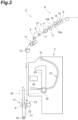
FIG. 2 is a side view illustrating a spinning unit inFIG. 1 . -
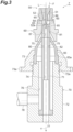
FIG. 3 is a sectional view illustrating a pneumatic spinning device inFIG. 2 . -
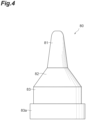
FIG. 4 is a front view illustrating a hollow guide shaft inFIG. 3 . -
FIG. 5 is a sectional view illustrating the hollow guide shaft inFIG. 3 . -
FIG. 6 is an enlarged view of part ofFIG. 5 . -
FIG. 7A is a sectional view illustrating an example of wound fibers to be wound around core fibers.FIG. 7B is a sectional view illustrating another example of wound fibers to be wound around core fibers. -
FIG. 8 is a graph indicating a relationship between a fiber passage and an introduction opening, and hairiness. - An embodiment will be explained hereinafter with reference to the drawings. In each of the drawings, the same or corresponding elements are denoted with the same reference numerals, and an overlapping explanation thereof is omitted.
- As illustrated in
FIG. 1 , aspinning machine 1 includes a plurality ofspinning units 2, ayarn joining cart 3, a doffing cart (not illustrated), afirst end frame 4, and asecond end frame 5. The plurality of spinningunits 2 are arranged in a row. Eachspinning unit 2 generates yarn Y and winds the yarn Y into a package P. When the yarn Y is cut or the yarn Y is broken for some reason in onespinning unit 2, theyarn joining cart 3 performs a yarn joining operation in thespinning unit 2. When a package P is fully wound in onespinning unit 2, the doffing cart doffs the package P and supplies a new bobbin B to thespinning unit 2. - The
first end frame 4 accommodates a collecting device configured to collect fiber wastes, yarn wastes, and the like generated in thespinning units 2, and other components. Thesecond end frame 5 accommodates, for example, an air supplier that adjusts the air pressure of compressed air (air) to be supplied to thespinning machine 1 and supplies the air to each part of thespinning machine 1, and a drive motor for supplying power to each part of thespinning units 2. Thesecond end frame 5 is provided with amachine control device 41, adisplay screen 42, andinput keys 43. Themachine control device 41 centrally manages and controls each part of the spinningmachine 1. Thedisplay screen 42 can display, for example, information on the settings and the state of thespinning units 2. The setting work for thespinning units 2 is performed by an operator's proper operation using theinput keys 43. - As illustrated in
FIGs. 1 and2 , each of thespinning units 2 includes adrafting device 6, apneumatic spinning device 7, ayarn monitoring device 8, atension sensor 9, ayarn storage device 11, awaxing device 12, and a windingdevice 13, in this order from the upstream side in the traveling direction of the yarn Y. Aunit controller 10 is provided for a predetermined number ofspinning units 2, and controls operations of thespinning units 2. - The
drafting device 6 drafts sliver (fiber bundle) S. Thedrafting device 6 has a pair ofback rollers 14, a pair ofthird rollers 15, a pair ofmiddle rollers 16, and a pair offront rollers 17, in order from the upstream side in the traveling direction of the sliver S. Each pair ofrollers second end frame 5 or the drive motor provided in each of thespinning units 2. The bottom roller of the pair ofmiddle rollers 16 is provided with anapron belt 18a. The top roller of the pair ofmiddle rollers 16 is provided with anapron belt 18b. - The
pneumatic spinning device 7 twists the fiber bundle (fibers) F drafted by thedrafting device 6 with a swirling flow of air to generate the yarn Y. Theyarn monitoring device 8 monitors information about the traveling yarn Y between thepneumatic spinning device 7 and theyarn storage device 11, and detects the presence of yarn defect on the basis of the monitored information. When any yarn defect is detected, theyarn monitoring device 8 transmits a yarn defect detection signal to theunit controller 10. Theyarn monitoring device 8 detects, for example, thickness abnormality of the yarn Y and a foreign matter or the like contained in the yarn Y as a yarn defect. - The
tension sensor 9 measures tension of the traveling yarn Y between thepneumatic spinning device 7 and theyarn storage device 11 in the path between thepneumatic spinning device 7 and the windingdevice 13, and transmits a tension measurement signal to theunit controller 10. When theunit controller 10 detects that there is an abnormality on the basis of the detection result of theyarn monitoring device 8 and thetension sensor 9, the yarn Y is cut in thespinning unit 2. Specifically, the air supply to thepneumatic spinning device 7 is stopped and generation of the yarn Y is suspended, whereby the yarn Y is cut. Alternatively, the yarn Y may be cut by a cutter separately provided. - The waxing
device 12 applies wax to the yarn Y between theyarn storage device 11 and the windingdevice 13. Theyarn storage device 11 removes slack of the yarn Y between thepneumatic spinning device 7 and the windingdevice 13. Theyarn storage device 11 has the function of stably drawing out the yarn Y from thepneumatic spinning device 7, the function of storing the yarn Y delivered from thepneumatic spinning device 7 in the yarn joining operation by theyarn joining cart 3 to prevent slacking of the yarn Y, and the function of preventing variation in tension of the yarn Y downstream from theyarn storage device 11 from propagating to thepneumatic spinning device 7. - The winding
device 13 winds the generated yarn Y around a bobbin B to form the package P. The windingdevice 13 has acradle arm 21, a windingdrum 22, and atraverse guide 23. Thecradle arm 21 rotatably supports the bobbin B. Thecradle arm 21 is swingably supported with asupport shaft 24 to bring the surface of the bobbin B or the surface of the package P into contact with the surface of the windingdrum 22 with proper pressure. A drive motor (not illustrated) in thesecond end frame 5 drives the windingdrums 22 of the plurality of spinningunits 2 simultaneously. In this manner, in each of thespinning units 2, the bobbin B or the package P is rotated in a winding direction. Thetraverse guide 23 of each of thespinning units 2 is provided on ashaft 25 shared by the plurality of spinningunits 2. When the drive motor of thesecond end frame 5 drives theshaft 25 in a rotating shaft direction of the windingdrum 22 in a reciprocating manner, thetraverse guide 23 traverses the yarn Y in a predetermined width relative to the bobbin B or the package P that is rotating. - When the yarn Y is cut or the yarn Y is broken for some reason in one
spinning unit 2, theyarn joining cart 3 travels to thespinning unit 2 to perform a yarn joining operation. Theyarn joining cart 3 includes ayarn joining device 26, asuction pipe 27, and asuction mouth 28. Thesuction pipe 27 is rotatably supported by asupport shaft 31, and catches the yarn Y from thepneumatic spinning device 7 and guides the yarn Y to theyarn joining device 26. Thesuction mouth 28 is rotatably supported by asupport shaft 32, and catches the yarn Y from the windingdevice 13 and guides the yarn Y to theyarn joining device 26. Theyarn joining device 26 joins the guided yarns Y. Theyarn joining device 26 is a splicer using compressed air, a piecer using seed yarn, or a knotter mechanically joining the yarn Y, or other devices. - Referring to
FIGs. 3 and4 , a configuration of thepneumatic spinning device 7 will be described in detail. Hereinafter the upstream side in the traveling direction of the fiber bundle F and the yarn Y is simply referred to as "upstream side", and the downstream side in the traveling direction of the fiber bundle F and the yarn Y is simply referred to as "downstream side". The axial direction of thehollow guide shaft 80 is simply referred to as "axial direction". - As illustrated in
FIG. 3 , thepneumatic spinning device 7 includes afiber guide 50, anozzle block 60, and a hollowguide shaft unit 70. Thefiber guide 50, thenozzle block 60, and the hollowguide shaft unit 70 are aligned on a line L along the axial direction from the upstream side toward the downstream side in a direction along the line L. - The
fiber guide 50 guides the fiber bundle F supplied from thedrafting device 6. Thefiber guide 50 has aguide hole 51 that guides the fiber bundle F. Thefiber guide 50 is provided with aneedle 52 disposed along the line L. Atip 52a of theneedle 52 is located downstream of thefiber guide 50. Thepneumatic spinning device 7 twists the fiber bundle F, guided from thefiber guide 50, by the swirling air flow in aspace 64 formed between thenozzle block 60 and the hollowguide shaft unit 70. Thefiber guide 50 is disposed at an upstream side end of thenozzle block 60. - The
nozzle block 60 has thespace 64 into which the fiber bundle F is introduced and a plurality ofnozzles 65 through which air to be injected into thespace 64 passes through to generate the swirling air flow. In thespace 64, fibers of the introduced fiber bundle F are swirled by the swirling air flow. The plurality ofnozzles 65 are arranged at equal angular intervals around thespace 64. - The hollow
guide shaft unit 70 has thehollow guide shaft 80, aguide pipe 71, asupport member 72, and a fixing member (holding member) 73. As illustrated inFIGs. 3 ,4 , and5 , thehollow guide shaft 80 has a first shaft portion (shaft portion) 81, asecond shaft portion 82, and athird shaft portion 83. Thefirst shaft portion 81, thesecond shaft portion 82, and thethird shaft portion 83 are aligned from the upstream side toward the downstream side and are integrally formed. A downstream side end of thethird shaft portion 83 is provided with aflange 83a. Thehollow guide shaft 80 is formed of metal, such as stainless steel. Thehollow guide shaft 80 may be formed of ceramic. Thehollow guide shaft 80 is also referred to as spindle. - The
first shaft portion 81 has afiber introduction hole 86 into which the fiber bundle F from thefiber guide 50 is introduced, afiber passage 85 that is continuous with thefiber introduction hole 86 and extends along the axial direction, and afiber passage 87 that is continuous with the downstream end of thefiber passage 85 and extends along the axial direction. Thefiber passage 87 leads to the inside of thesecond shaft portion 82 and thethird shaft portion 83, which are hollow. The outer shape of thefirst shaft portion 81 is a truncated cone spreading from the upstream side toward the downstream side. The outer shape of thesecond shaft portion 82 is a truncated cone spreading from the upstream side toward the downstream side, and spreads at a greater angle than thefirst shaft portion 81 does. At least an end area of the upstream side of thefirst shaft portion 81 is disposed in thenozzle block 60. - As illustrated in
FIG. 3 , theguide pipe 71 is provided with apassage 74 configured to guide the fiber bundle F to the outside of thepneumatic spinning device 7. Thepassage 74 is open to the upstream side and the downstream side on the line L. An inner diameter of a downstream side portion of thepassage 74 is larger than an inner diameter of an upstream side portion of thepassage 74. The end area of the upstream side of theguide pipe 71 is provided with a plurality ofnozzles 75 through which air to be injected into thepassage 74 passes. The plurality ofnozzles 75 are provided, for example, at equal angular intervals around line L. - The
support member 72 is provided with ahousing hole 76 opening to the upstream side and ayarn guiding channel 77 opening to the upstream side and the downstream side. The upstream side end of theyarn guiding channel 77 is connected to the downstream side end of thehousing hole 76. An inner diameter of theyarn guiding channel 77 is substantially equal to the inner diameter of the downstream side portion of thepassage 74 in theguide pipe 71 and smaller than the inner diameter of thehousing hole 76. Anair supply pipe 78 that is continuous to thehousing hole 76 is attached to thesupport member 72. An upstream side end of thesupport member 72 has amale thread 72a. - A fixing
member 73 is a cap-shaped nut provided with aflange 73a. In the hollowguide shaft unit 70, theguide pipe 71 is disposed in thehousing hole 76 of thesupport member 72, and thehollow guide shaft 80 is disposed at the upstream side end of thesupport member 72 to cover the upstream side end of theguide pipe 71. Accordingly, thefiber passage 87 of thehollow guide shaft 80 is connected to thepassage 74 of theguide pipe 71, and thepassage 74 of theguide pipe 71 is connected to theyarn guiding channel 77 of thesupport member 72. In this state, the fixingmember 73 is screwed onto themale thread 72a of thesupport member 72 while being engaged with theflange 83a of thehollow guide shaft 80. - In the
pneumatic spinning device 7 configured as described above, at the start of spinning operation, air is injected into thenozzle block 60 from the plurality ofnozzles 65 and air is injected into thepassage 74 from the plurality ofnozzles 75. In this manner, the fiber bundle F introduced from thedrafting device 6 into thespace 64 through theguide hole 51 is led to the downstream side through thepassage 74 and theyarn guiding channel 77. Thereafter, injection of air from the plurality ofnozzles 65 into thespace 64 continues, and the injection of air from the plurality ofnozzles 75 into thepassage 74 is stopped, and the spinning operation proceeds to normal spinning operation. The swirling air flow generated in thespace 64 allows fibers constituting the fiber bundle F to swirl. A downstream end of fibers of the fiber bundle F introduced into thefiber introduction hole 86 is wound into preceding fibers sequentially to become the core (core fibers) of the yarn Y to be generated, and the upstream end of the fibers is swung by the swirling air flow to be sequentially wound around the core fibers (wound fibers). Part of a single fiber becomes the core fiber and a different part becomes the wound fiber. The yarn Y generated by twisting the fiber bundle F is led to the downstream side through thepassage 74 and theyarn guiding channel 77. - Next, key parts of the
hollow guide shaft 80 of the present embodiment will be described. - As illustrated in
FIGs. 5 and6 , in thehollow guide shaft 80, thefirst shaft portion 81 has thefiber introduction hole 86 and thefiber passage 85. Thefiber introduction hole 86 is a space that penetrates from the outside of thehollow guide shaft 80 to thefiber passage 85. Thefiber introduction hole 86 is a hole in which a shape of a cross-section perpendicular to the axial direction is circular. The circle may be an oval. The opening end (upstream side end or edge) of thefiber introduction hole 86 constitutes an introduction opening 89 of the fiber bundle F. Theintroduction opening 89 is a boundary between the inside and the outside of thehollow guide shaft 80. Aninner surface 86x of thefiber introduction hole 86 is a curved surface that widens toward the opening side. - The
fiber passage 85 is a space continuous from thefiber introduction hole 86 toward the downstream side. Level difference is not formed at the boundary between aninner surface 85x of thefiber passage 85 and theinner surface 86x of thefiber introduction hole 86. Thefiber passage 85 is a hole in which a shape of a cross-section perpendicular to the axial direction is circular. The circle may be an oval. Theinner surface 85x of thefiber passage 85 is a surface along the axial direction. - As illustrated in
FIG. 6 , where A is the inner diameter of thefiber passage 85 and B is a diameter of the introduction opening 89 of thefiber introduction hole 86, 1.5 ≤ B/A ≤ 1.8 is established. More specifically, 1.6 ≤ B/A ≤ 1.75 is established. In the present embodiment, B/A is 1.63. The diameter of the introduction opening 89 can also be said to be a distance between vertices of thehollow guide shaft 80 when the vertices are connected by a straight line in a side view of thehollow guide shaft 80. The inner diameter of thefiber passage 85 is the diameter of thefiber passage 85. The inner diameter of thefiber passage 85 may be an average value, a minimum value, or a maximum value of the inner diameters at a plurality of positions in thefiber passage 85. The diameter of the introduction opening 89 is a diameter of theintroduction opening 89. - Where R is the radius of curvature of the
inner surface 86x that is a curved surface, 0.25 mm ≤ R ≤ 0.35 mm is established. In the present embodiment, R is 0.3 mm ± 0.05 mm. - Where D is the outer diameter of the first shaft portion 81 (refer to
FIG. 5 ), 2.8 mm ≤ D ≤ 4.0 mm and 0.8 mm ≤ A < 1.25 mm are established. In the present embodiment, D is 2.8 mm. Also, 0.8 mm ≤ A ≤ 1.1 mm is established. The outer diameter of thefirst shaft portion 81 is a distance, viewed from the side of the hollow guide shaft 80 (direction perpendicular to the axial direction), between intersection points da and db of a straight line passing through the upstream side end of thefirst shaft portion 81 and perpendicular to the axial direction (dashed line extending in the right-left direction inFIG. 5 ) and extension lines of periphery of the first shaft portion 81 (dashed lines respectively extending in diagonally upward and downward directions inFIG. 5 ). The inner diameter of thefiber passage 85, the diameter of the introduction opening 89, the radius of curvature of theinner surface 86x, and the outer diameter of thefirst shaft portion 81 can be measured by non-destructive testing equipment or the like, and can be measured by, for example, a 3D shape measuring machine VR-5000 (Keyence Corporation). - The following findings are obtained regarding the behavior of the core fibers and the wound fibers that wrap around the core fibers when the fibers of the fiber bundle F are introduced into the
fiber introduction hole 86 in thehollow guide shaft 80.FIG. 7A is an enlarged sectional view of the upstream side portion of thehollow guide shaft 80 according to the present embodiment.FIG. 7B is an enlarged sectional view of an upstream side portion of ahollow guide shaft 180 according to the comparative example. Thehollow guide shaft 180 according to the comparative example differs from thehollow guide shaft 80 in that afiber introduction hole 186 is formed in place of thefiber introduction hole 86. The radius of curvature of aninner surface 186x of thefiber introduction hole 186 is smaller than the radius of curvature of theinner surface 86x of thefiber introduction hole 86. The B/A of thehollow guide shaft 180 is smaller than the B/A of thehollow guide shaft 80, for example, 1.21. -
FIG. 8 is a graph indicating a relationship between a fiber passage and an introduction opening, and hairiness. InFIG. 8 , the vertical axis is Hairiness, which corresponds to hairiness, and the horizontal axis is B/A. Hairiness is a total length of hairiness in the generated yarn Y for a length of 1 cm. Hairiness can be measured, for example, with a yarn evenness tester UT-6 (Uster Technologies K.K.). Data inFIG. 8 is data in a case where the yarn Y is generated at a typical spinning speed (for example, 540 m/min). - As illustrated in
FIGs. 7A and 7B , as B/A becomes larger, a winding start position, where wound fibers Fb, out of the fiber bundle F that is to be introduced into thefiber introduction hole 86, start winding around core fibers Fa (hereinafter also simply referred to as "winding start position"), can be separated from the core fibers Fa. As a result, winding force with which the wound fibers Fb are wound around the core fibers Fa can be weakened, and tightness of the yarn Y to be generated can be reduced to increase the hairiness, as illustrated inFIG. 8 . - As R that is the radius of curvature of the
inner surface 86x becomes larger, a bent angle of the wound fibers Fb becomes larger, the wound fibers Fb are wound around the core fibers Fa with low tension applied to the wound fibers Fb, and tightening force of the yarn Y is reduced. As R that is the radius of curvature of theinner surface 86x becomes larger, an area where the wound fibers Fb make contact with theinner surface 86x becomes larger, frictional resistance of thefirst shaft portion 81 with respect to the wound fiber Fb increases, whirling force of the swirling air flow on the wound fibers Fb decreases, and the tightening force of the yarn Y becomes weak. - In particular, when B/A is 1.5 or higher, the hairiness can be increased above a required specified value α. The specified value α is, for example, a value corresponding to a lower threshold determined from required quality of the yarn Y and other factors. In the present embodiment, the yarn Y having tightness smaller than a certain value, in other words, the yarn Y having a soft texture, is desired, and the specified value α corresponding to the desire is defined. In other words, the
hollow guide shaft 80 has a structure for generating the yarn Y with much hairiness, that is, the yarn Y with a soft texture. - As in the foregoing, with the
hollow guide shaft 80, since B/A is 1.5 or more, it is possible to generate the yarn Y with hairiness increased above the specified value α. If B/A is too large, it is difficult for the wound fibers Fb to be wound around the core fibers Fa, and the possibility of difficulty in generating the yarn Y increases, and thus, B/A is set to 1.8 or less, to reliably generate the yarn Y. Thus, it is possible to reliably generate the yarn Y with hairiness increased above the specified value α. It is possible to generate the yarn Y with a larger yarn diameter. - In the
hollow guide shaft 80, 1.6 ≤ B/A ≤ 1.75 is established. In this case, with the winding force further reduced, the hairiness of the yarn Y to be generated can be further increased, and with the wound fibers Fb gently and securely wound around the core fibers Fa, the yarn Y can be more reliably generated. - In the
hollow guide shaft 80, theinner surface 86x of thefiber introduction hole 86 has a curved surface that widens toward the opening side. Where R is the radius of curvature of theinner surface 86x, 0.25 mm ≤ R ≤ 0.35 mm is established. In this case, as the fiber bundle F is introduced into thefiber introduction hole 86, the fibers (wound fibers Fb) of the fiber bundle F easily float from theinner surface 86x of thefiber introduction hole 86, and thus resistance applied to the fiber band Fb can be reduced and the winding force can be decreased. In this manner, it is possible to further increase the hairiness of the yarn Y to be generated. - In the
hollow guide shaft 80, where D is the outer diameter of thefirst shaft portion 81, 2.8 mm ≤ D ≤ 4.0 mm and 0.8 mm ≤ A < 1.25 mm are established. In this case, it is possible to form thefirst shaft portion 81 having durability while keeping B/A in the above-described range. In other words, since D and A are within the above-described ranges, the thickness of thefirst shaft portion 81 can be secured. If the outer diameter D is smaller than 2.8 mm, it is difficult to stably form thehollow guide shaft 80 according to the present embodiment. When the outer diameter D of thefirst shaft portion 81 is 4.0 mm or less, a swirling diameter of the fibers swirled near thefiber introduction hole 86 does not become too large, and thus the fibers can be swirled stably at a desired speed without the fiber rotation speed being excessively decreased. If A is within the above-described range, the inner diameter of thefiber passage 85 is large enough for the general diameter of the fibers (yarn Y) introduced through thefiber introduction hole 86, so that the fibers can move smoothly through thefiber passage 85 even if the yarn Y has much hairiness. - In the
hollow guide shaft 80, 0.8 mm ≤ A ≤ 1.1 mm is established. In this case, the hairiness can be increased more efficiently, especially in a case where the inner diameter A is 1.1 mm or less. A distance between the fibers passing through the fiber passage 85 (core fibers Fa) and the wound fibers Fb can be brought closer together. In other words, the downstream end of the wound fibers Fb is closer to a center of the first shaft portion 81 (fiber passage 85), so that the fibers can be more easily controlled and the hairiness can be increased efficiently. - In the
hollow guide shaft 80, thefirst shaft portion 81 is formed of metal. In this case, a shape of thehollow guide shaft 80 can be achieved with high precision. - The
pneumatic spinning device 7 has thefiber guide 50, thenozzle block 60, and thehollow guide shaft 80. Since thepneumatic spinning device 7 includes thehollow guide shaft 80, the above-described action effect is exerted, that is, the yarn Y with hairiness increased above the specified value α can be generated. - The spinning
machine 1 includes thedrafting device 6, thepneumatic spinning device 7, and the windingdevice 13. Since the spinningmachine 1 includes thepneumatic spinning device 7, the above-described action effect is exerted, that is, the yarn Y with hairiness increased above the specified value α can be generated. - Note that in the
hollow guide shaft 80 according to the present embodiment, the surface shape of theinner surface 86x of thefiber introduction hole 86 is not particularly limited and may have a flat surface that widens toward the opening side (what is called a chamfered surface). In this case, theinner surface 86x of thefiber introduction hole 86 can be easily machined and thefiber introduction hole 86 can be formed with high precision. An inclining angle of theinner surface 86x as a flat surface is not particularly limited and may be any angle. For example, the inclining angle may be inclined by 45° or 60° with respect to the plane along the axial direction. - As in the foregoing, an aspect of the present invention is not limited to the above-described embodiment, and various changes can be made without departing from the gist of the invention.
- In the above-described embodiment, the shape of the introduction opening 89 is not limited and may be a shape other than a circle. In this case, the diameter of the introduction opening 89 may be a diameter of an inscribed circle of the introduction opening 89, a diameter of a circumscribed circle thereof, or an average value of these diameters. The shape of
fiber passage 85 is not limited and may be a shape other than a circle. In this case, the inner diameter of thefiber passage 85 may be a diameter of an inscribed circle of thefiber passage 85, a diameter of a circumscribed circle thereof, or an average value of these diameters. - In the above-described embodiment, the
inner surface 85x does not have to be parallel to the axial direction, may be inclined, may be concave, and/or may convex. The radius of curvature of theinner surface 86x does not have to be constant. In this case, R may be a maximum value, a minimum value, or an average value of the radius of curvature of theinner surface 86x. In the above-described embodiment, the outer shape of thefirst shaft portion 81 may be a shape other than a truncated cone. - In the above-described embodiment, the hollow
guide shaft unit 70 does not have to have thenozzles 75. Of the hollowguide shaft unit 70, thefirst shaft portion 81 may be formed separately from thesecond shaft portion 82 and thethird shaft portion 83. In this case, if the hollowguide shaft unit 70 has thenozzles 75, thefirst shaft portion 81 may be integrally formed with the upstream side end of theguide pipe 71 provided with thenozzles 75. Thesecond shaft portion 82 and thethird shaft portion 83 may be integrally formed with the fixingmember 73. - In the above-described embodiment, the
pneumatic spinning device 7 may have a configuration in which theneedle 52 is not provided and the downstream end of thefiber guide 50 may prevent the twists of the fiber bundle F from being transmitted to the upstream side of thepneumatic spinning device 7. - In the above-described embodiment, the
fiber guide 50 and thenozzle block 60 may be integrally configured. - In the
spinning unit 2 according to the above-described embodiment, theyarn storage device 11 has a function of drawing the yarn Y from thepneumatic spinning device 7. However, the yarn Y may be drawn from thepneumatic spinning device 7 by a delivery roller and a nip roller. When the yarn Y is drawn from thepneumatic spinning device 7 by the delivery roller and the nip roller, a slack tube configured to absorb slack of the yarn Y with suction air flow and/or a mechanical compensator may be provided, instead of theyarn storage device 11, or in addition to theyarn storage device 11. - In the spinning
machine 1 according to the above-described embodiment, in the height direction of the machine, the devices are disposed such that the yarn Y supplied from the upper side is wound up on the lower side. However, the devices may be disposed such that the yarn Y supplied from the lower side is wound up on the upper side. - In the spinning
machine 1 according to the above-described embodiment, at least one of the bottom rollers of thedrafting device 6 and thetraverse guide 23 are driven by motive power from the second end frame 5 (that is, in common with a plurality of the spinning units 2). However, each part (such as thedrafting device 6, thepneumatic spinning device 7, and the winding device 13) of thespinning unit 2 may be driven independently in each of thespinning units 2. At least one of the devices related to yarn joining (yarn joining device 26,suction pipe 27, suction mouth 28) may be provided in each of thespinning units 2 instead of in theyarn joining cart 3. - In the above-described embodiment, in the traveling direction of the yarn Y, the
tension sensor 9 may be disposed upstream of theyarn monitoring device 8. Theunit controller 10 may be provided for each of thespinning units 2. In thespinning units 2, the waxingdevice 12, thetension sensor 9, and theyarn monitoring device 8 may be omitted. - In the above-described embodiment, the spinning
machine 1 is illustrated (refer toFIG. 1 ) such as to wind the package P in a cheese shape, but the spinningmachine 1 can wind the package P in a cone shape. In a case of the package P in a cone shape, traversing the yarn Y causes slack of the yarn Y, but the slack can be absorbed by theyarn storage device 11. In the above-described embodiment, the specified value α does not have to be a fixed value, but may be a value that varies depending on, for example, the raw material of the sliver S and the conditions of the yarn Y to be generated. - The materials and shapes of the components are not limited to the materials and shapes described above, and various materials and shapes can be employed. Each of the above values may include at least some error in design, manufacturing, measurement, or the like.
Claims (9)
- A hollow guide shaft (80) comprising a shaft portion (81) having a fiber introduction hole (86) into which fibers are introduced and a fiber passage (85) that is continuous with the fiber introduction hole (86) and extends along an axial direction, wherein
where A is an inner diameter of the fiber passage (85) and B is a diameter of an introduction opening (89) serving as an opening end of the fiber introduction hole (86), 1.5 ≤ B/A ≤ 1.8 is established. - The hollow guide shaft (80) according to claim 1, wherein 1.6 ≤ B/A ≤ 1.75 is established.
- The hollow guide shaft (80) according to claim 1 or 2, whereinan inner surface (86x) of the fiber introduction hole (86) has a curved surface that widens toward an opening side, andwhere R is a radius of curvature of the curved surface, 0.25 mm ≤ R ≤ 0.35 mm is established.
- The hollow guide shaft (80) according to claim 1 or 2, wherein an inner surface (86x) of the fiber introduction hole (86) has a flat surface that widens toward an opening side.
- The hollow guide shaft (80) according to any one of claims 1 to 4, wherein, where D is an outer diameter of the shaft portion (81), 2.8 mm ≤ D ≤ 4.0 mm and 0.8 mm ≤ A < 1.25 mm are established.
- The hollow guide shaft (80) according to claim 5, wherein 0.8 mm ≤ A ≤ 1.1 mm is established.
- The hollow guide shaft (80) according to any one of claims 1 to 6, wherein the shaft portion (81) is formed of metal.
- A pneumatic spinning device (7) comprising:a fiber guide (50) configured to guide fibers;a nozzle block (60) having a plurality of nozzles (65) through which air to be injected passes; andthe hollow guide shaft (80) according to any one of claims 1 to 7.
- A spinning machine (1) comprising:a drafting device (6) configured to draft fibers;the pneumatic spinning device (7) according to claim 8 configured to twist the fibers supplied from the drafting device (6) to generate yarn (Y); anda winding device (13) configured to wind the yarn (Y) generated by the pneumatic spinning device (7).
Applications Claiming Priority (1)
| Application Number | Priority Date | Filing Date | Title |
|---|---|---|---|
| JP2022155319A JP2024049074A (en) | 2022-09-28 | 2022-09-28 | Hollow guide shaft, air spinning device and spinning machine |
Publications (1)
| Publication Number | Publication Date |
|---|---|
| EP4357499A1 true EP4357499A1 (en) | 2024-04-24 |
Family
ID=88207523
Family Applications (1)
| Application Number | Title | Priority Date | Filing Date |
|---|---|---|---|
| EP23200126.3A Withdrawn EP4357499A1 (en) | 2022-09-28 | 2023-09-27 | Hollow guide shaft, pneumatic spinning device, and spinning machine |
Country Status (3)
| Country | Link |
|---|---|
| EP (1) | EP4357499A1 (en) |
| JP (1) | JP2024049074A (en) |
| CN (1) | CN117779266A (en) |
Citations (6)
| Publication number | Priority date | Publication date | Assignee | Title |
|---|---|---|---|---|
| JPH0413063U (en) | 1990-05-17 | 1992-02-03 | ||
| CN101294319A (en) * | 2008-05-26 | 2008-10-29 | 东华大学 | Air-jet vortex spinning device with low noil |
| CN103305979A (en) * | 2013-06-24 | 2013-09-18 | 东华大学 | Air-injection vortex-spinning groove-shaped low-fiber hollow spindle |
| CN102787405B (en) * | 2012-07-27 | 2014-11-26 | 绍兴文理学院 | Hollow spindle with spiral guide grooves |
| CN203977003U (en) * | 2014-07-15 | 2014-12-03 | 浙江华孚色纺有限公司 | A kind of spinning apparatus of vortex spinning for spinning AB yarn |
| US10851478B2 (en) * | 2016-04-29 | 2020-12-01 | Savio Macchine Tessili S.P.A. | Air-jet type spinning device |
-
2022
- 2022-09-28 JP JP2022155319A patent/JP2024049074A/en active Pending
-
2023
- 2023-08-29 CN CN202311096597.XA patent/CN117779266A/en active Pending
- 2023-09-27 EP EP23200126.3A patent/EP4357499A1/en not_active Withdrawn
Patent Citations (6)
| Publication number | Priority date | Publication date | Assignee | Title |
|---|---|---|---|---|
| JPH0413063U (en) | 1990-05-17 | 1992-02-03 | ||
| CN101294319A (en) * | 2008-05-26 | 2008-10-29 | 东华大学 | Air-jet vortex spinning device with low noil |
| CN102787405B (en) * | 2012-07-27 | 2014-11-26 | 绍兴文理学院 | Hollow spindle with spiral guide grooves |
| CN103305979A (en) * | 2013-06-24 | 2013-09-18 | 东华大学 | Air-injection vortex-spinning groove-shaped low-fiber hollow spindle |
| CN203977003U (en) * | 2014-07-15 | 2014-12-03 | 浙江华孚色纺有限公司 | A kind of spinning apparatus of vortex spinning for spinning AB yarn |
| US10851478B2 (en) * | 2016-04-29 | 2020-12-01 | Savio Macchine Tessili S.P.A. | Air-jet type spinning device |
Also Published As
| Publication number | Publication date |
|---|---|
| CN117779266A (en) | 2024-03-29 |
| JP2024049074A (en) | 2024-04-09 |
Similar Documents
| Publication | Publication Date | Title |
|---|---|---|
| EP3153614B1 (en) | Spinning machine | |
| EP3098337B1 (en) | Air spinning device, spinning unit, and spinning method using the air spinning device | |
| JP2013049932A (en) | Spinning machine | |
| EP3156526B1 (en) | Hollow guide shaft, air-jet spinning device, and textile machinery | |
| EP3075890B1 (en) | Draft device and spinning machine | |
| EP2453044B1 (en) | Spinning method by using air spinning device and air spinning device | |
| EP4357498B1 (en) | Hollow guide shaft, pneumatic spinning device and spinning machine | |
| EP3153613A1 (en) | Drafting device, spinning machine, and method of spinning technical field | |
| EP3470559B1 (en) | Pneumatic spinning device, and spinning machine | |
| JP2024049074A (en) | Hollow guide shaft, air spinning device and spinning machine | |
| CN112342648B (en) | Air spinning device and fiber guiding member | |
| CN112501729B (en) | Spinning unit, air spinning device, spinning machine and spinning method | |
| JP2018178311A (en) | Spinning machine, air spinning method, and yarn | |
| EP3026152A2 (en) | Fiber collecting device, drafting device, and spinning machine | |
| JP2021110062A (en) | Draft device, spinning machine, spinning method, and draft roller | |
| JP2017025437A (en) | Hollow guide shaft body unit, air spinning device, spinning machine, and assembly method of hollow guide shaft body unit | |
| EP3150531B1 (en) | Yarn threading member, yarn storage device and yarn winder | |
| JP2021017655A (en) | Hollow guide shaft body, hollow guide unit, and manufacturing method of hollow guide unit | |
| JP2016125149A (en) | Hollow guide shaft body, air spinning device and spinning machine | |
| JP2019052387A (en) | Spinning machine | |
| JP2024036746A (en) | Fiber guide, air spinning device, and air spinning machine | |
| JP2021042509A (en) | Spinning unit and method for producing spun yarn | |
| JP2023026083A (en) | Fiber guide, air spinning device, and air spinning unit | |
| CN114645343A (en) | Spinning machine, fiber guide and air jet spinning device |
Legal Events
| Date | Code | Title | Description |
|---|---|---|---|
| PUAI | Public reference made under article 153(3) epc to a published international application that has entered the european phase |
Free format text: ORIGINAL CODE: 0009012 |
|
| STAA | Information on the status of an ep patent application or granted ep patent |
Free format text: STATUS: THE APPLICATION HAS BEEN PUBLISHED |
|
| AK | Designated contracting states |
Kind code of ref document: A1 Designated state(s): AL AT BE BG CH CY CZ DE DK EE ES FI FR GB GR HR HU IE IS IT LI LT LU LV MC ME MK MT NL NO PL PT RO RS SE SI SK SM TR |
|
| STAA | Information on the status of an ep patent application or granted ep patent |
Free format text: STATUS: REQUEST FOR EXAMINATION WAS MADE |
|
| 17P | Request for examination filed |
Effective date: 20240906 |
|
| RBV | Designated contracting states (corrected) |
Designated state(s): AL AT BE BG CH CY CZ DE DK EE ES FI FR GB GR HR HU IE IS IT LI LT LU LV MC ME MK MT NL NO PL PT RO RS SE SI SK SM TR |
|
| GRAP | Despatch of communication of intention to grant a patent |
Free format text: ORIGINAL CODE: EPIDOSNIGR1 |
|
| STAA | Information on the status of an ep patent application or granted ep patent |
Free format text: STATUS: GRANT OF PATENT IS INTENDED |
|
| INTG | Intention to grant announced |
Effective date: 20250423 |
|
| STAA | Information on the status of an ep patent application or granted ep patent |
Free format text: STATUS: THE APPLICATION IS DEEMED TO BE WITHDRAWN |
|
| 18D | Application deemed to be withdrawn |
Effective date: 20250826 |