EP4357299A1 - Hydrogen production system - Google Patents
Hydrogen production system Download PDFInfo
- Publication number
- EP4357299A1 EP4357299A1 EP22861059.8A EP22861059A EP4357299A1 EP 4357299 A1 EP4357299 A1 EP 4357299A1 EP 22861059 A EP22861059 A EP 22861059A EP 4357299 A1 EP4357299 A1 EP 4357299A1
- Authority
- EP
- European Patent Office
- Prior art keywords
- heat medium
- heat
- hydrogen
- container
- production system
- Prior art date
- Legal status (The legal status is an assumption and is not a legal conclusion. Google has not performed a legal analysis and makes no representation as to the accuracy of the status listed.)
- Pending
Links
Images


Classifications
-
- C—CHEMISTRY; METALLURGY
- C01—INORGANIC CHEMISTRY
- C01B—NON-METALLIC ELEMENTS; COMPOUNDS THEREOF; METALLOIDS OR COMPOUNDS THEREOF NOT COVERED BY SUBCLASS C01C
- C01B3/00—Hydrogen; Gaseous mixtures containing hydrogen; Separation of hydrogen from mixtures containing it; Purification of hydrogen; Reversible storage of hydrogen
- C01B3/02—Production of hydrogen; Production of gaseous mixtures containing hydrogen
- C01B3/04—Production of hydrogen; Production of gaseous mixtures containing hydrogen by decomposition of inorganic compounds
-
- C—CHEMISTRY; METALLURGY
- C01—INORGANIC CHEMISTRY
- C01B—NON-METALLIC ELEMENTS; COMPOUNDS THEREOF; METALLOIDS OR COMPOUNDS THEREOF NOT COVERED BY SUBCLASS C01C
- C01B3/00—Hydrogen; Gaseous mixtures containing hydrogen; Separation of hydrogen from mixtures containing it; Purification of hydrogen; Reversible storage of hydrogen
- C01B3/0005—Reversible storage of hydrogen, e.g. by hydrogen getters or electrodes
- C01B3/001—Reversible storage of hydrogen, e.g. by hydrogen getters or electrodes characterised by the uptaking media; Treatment thereof
- C01B3/0018—Inorganic elements or compounds, e.g. oxides, nitrides, borohydrides or zeolites; Solutions thereof
- C01B3/0026—Metals or metal hydrides
-
- B—PERFORMING OPERATIONS; TRANSPORTING
- B01—PHYSICAL OR CHEMICAL PROCESSES OR APPARATUS IN GENERAL
- B01D—SEPARATION
- B01D1/00—Evaporating
- B01D1/0011—Heating features
- B01D1/0041—Use of fluids
- B01D1/0052—Use of a liquid transfer medium or intermediate fluid, e.g. bain-marie
-
- B—PERFORMING OPERATIONS; TRANSPORTING
- B01—PHYSICAL OR CHEMICAL PROCESSES OR APPARATUS IN GENERAL
- B01J—CHEMICAL OR PHYSICAL PROCESSES, e.g. CATALYSIS OR COLLOID CHEMISTRY; THEIR RELEVANT APPARATUS
- B01J19/00—Chemical, physical or physico-chemical processes in general; Their relevant apparatus
- B01J19/08—Processes employing the direct application of electric or wave energy, or particle radiation; Apparatus therefor
- B01J19/12—Processes employing the direct application of electric or wave energy, or particle radiation; Apparatus therefor employing electromagnetic waves
- B01J19/122—Incoherent waves
- B01J19/127—Sunlight; Visible light
-
- B—PERFORMING OPERATIONS; TRANSPORTING
- B01—PHYSICAL OR CHEMICAL PROCESSES OR APPARATUS IN GENERAL
- B01J—CHEMICAL OR PHYSICAL PROCESSES, e.g. CATALYSIS OR COLLOID CHEMISTRY; THEIR RELEVANT APPARATUS
- B01J6/00—Heat treatments such as Calcining; Fusing ; Pyrolysis
-
- B—PERFORMING OPERATIONS; TRANSPORTING
- B01—PHYSICAL OR CHEMICAL PROCESSES OR APPARATUS IN GENERAL
- B01J—CHEMICAL OR PHYSICAL PROCESSES, e.g. CATALYSIS OR COLLOID CHEMISTRY; THEIR RELEVANT APPARATUS
- B01J7/00—Apparatus for generating gases
-
- C—CHEMISTRY; METALLURGY
- C01—INORGANIC CHEMISTRY
- C01B—NON-METALLIC ELEMENTS; COMPOUNDS THEREOF; METALLOIDS OR COMPOUNDS THEREOF NOT COVERED BY SUBCLASS C01C
- C01B3/00—Hydrogen; Gaseous mixtures containing hydrogen; Separation of hydrogen from mixtures containing it; Purification of hydrogen; Reversible storage of hydrogen
- C01B3/02—Production of hydrogen; Production of gaseous mixtures containing hydrogen
- C01B3/04—Production of hydrogen; Production of gaseous mixtures containing hydrogen by decomposition of inorganic compounds
- C01B3/042—Decomposition of water
-
- B—PERFORMING OPERATIONS; TRANSPORTING
- B01—PHYSICAL OR CHEMICAL PROCESSES OR APPARATUS IN GENERAL
- B01J—CHEMICAL OR PHYSICAL PROCESSES, e.g. CATALYSIS OR COLLOID CHEMISTRY; THEIR RELEVANT APPARATUS
- B01J2219/00—Chemical, physical or physico-chemical processes in general; Their relevant apparatus
- B01J2219/00049—Controlling or regulating processes
- B01J2219/00051—Controlling the temperature
- B01J2219/00159—Controlling the temperature controlling multiple zones along the direction of flow, e.g. pre-heating and after-cooling
-
- C—CHEMISTRY; METALLURGY
- C01—INORGANIC CHEMISTRY
- C01B—NON-METALLIC ELEMENTS; COMPOUNDS THEREOF; METALLOIDS OR COMPOUNDS THEREOF NOT COVERED BY SUBCLASS C01C
- C01B2203/00—Integrated processes for the production of hydrogen or synthesis gas
- C01B2203/02—Processes for making hydrogen or synthesis gas
- C01B2203/0266—Processes for making hydrogen or synthesis gas containing a decomposition step
-
- C—CHEMISTRY; METALLURGY
- C01—INORGANIC CHEMISTRY
- C01B—NON-METALLIC ELEMENTS; COMPOUNDS THEREOF; METALLOIDS OR COMPOUNDS THEREOF NOT COVERED BY SUBCLASS C01C
- C01B2203/00—Integrated processes for the production of hydrogen or synthesis gas
- C01B2203/08—Methods of heating or cooling
- C01B2203/0805—Methods of heating the process for making hydrogen or synthesis gas
- C01B2203/0833—Heating by indirect heat exchange with hot fluids, other than combustion gases, product gases or non-combustive exothermic reaction product gases
-
- C—CHEMISTRY; METALLURGY
- C01—INORGANIC CHEMISTRY
- C01B—NON-METALLIC ELEMENTS; COMPOUNDS THEREOF; METALLOIDS OR COMPOUNDS THEREOF NOT COVERED BY SUBCLASS C01C
- C01B2203/00—Integrated processes for the production of hydrogen or synthesis gas
- C01B2203/08—Methods of heating or cooling
- C01B2203/0872—Methods of cooling
- C01B2203/0883—Methods of cooling by indirect heat exchange
-
- Y—GENERAL TAGGING OF NEW TECHNOLOGICAL DEVELOPMENTS; GENERAL TAGGING OF CROSS-SECTIONAL TECHNOLOGIES SPANNING OVER SEVERAL SECTIONS OF THE IPC; TECHNICAL SUBJECTS COVERED BY FORMER USPC CROSS-REFERENCE ART COLLECTIONS [XRACs] AND DIGESTS
- Y02—TECHNOLOGIES OR APPLICATIONS FOR MITIGATION OR ADAPTATION AGAINST CLIMATE CHANGE
- Y02E—REDUCTION OF GREENHOUSE GAS [GHG] EMISSIONS, RELATED TO ENERGY GENERATION, TRANSMISSION OR DISTRIBUTION
- Y02E60/00—Enabling technologies; Technologies with a potential or indirect contribution to GHG emissions mitigation
- Y02E60/30—Hydrogen technology
- Y02E60/36—Hydrogen production from non-carbon containing sources, e.g. by water electrolysis
Definitions
- the present disclosure relates to a hydrogen production system.
- PTL 1 discloses a system of electrolyzing seawater using a DC generated by a solar power generation device to generate a hydrogen gas.
- an object of at least one embodiment of the present disclosure is to provide a hydrogen production system capable of producing hydrogen with excellent thermal efficiency.
- a hydrogen production system includes at least one container which accommodates a hydrogen compound member, a heating device which heats an inside of the at least one container by a heat medium, a cooling device which cools the inside of the at least one container, and a water supply device which supplies water into the at least one container, and the heating device includes a sunlight focusing device which heats the heat medium by focusing sunlight and emitting to the heat medium.
- the heat medium heated by emitting the focused sunlight heats the hydrogen compound member accommodated in the container, and accordingly, the hydrogen can be produced with excellent thermal efficiency.
- a hydrogen production system 1 includes a container 2 which accommodates a hydrogen compound member 3, a heating device 4 that heats an inside of the container 2, a cooling device 5 which cools the inside of the container 2, and a water supply device 6 which supplies water into the container 2.
- a hydrogen release unit 7 and an oxygen release unit 8 are provided on the container 2.
- the hydrogen compound member 3 has a two-dimensional arrangement of a hydrogen compound represented by a chemical formula X m H n , and a stoichiometric ratio m:n is 1:1 to 3:4 (for example, XH, XH 2 , XH 3 , XH 4 , X 2 H 3 , or X 3 H 4 ).
- the element X is, for example, boron (B).
- the heating device 4 is for heating the inside of the container 2, that is, the hydrogen compound member 3 accommodated in the container 2.
- the heating device 4 may be configured such that a heat medium comes into direct contact with the hydrogen compound member 3 by supplying the heat medium into the container 2.
- the heating device 4 will be described as having a configuration in which the hydrogen compound member 3 accommodated in the container 2 is heated by causing the heat medium to flow through a heat medium passage 9 such as a jacket or a passage provided to cover an outer surface of the container 2 and exchanging heat between the heat medium and a gas in the container 2.
- the heat medium is not particularly limited, but a liquid heat medium such as water or oil is preferably used.
- the heating device 4 includes a heat medium circulation line 10 having one end connected to an inlet of the heat medium passage 9 and the other end connected to an outlet of the heat medium passage 9 to circulate the heat medium, and a sunlight focusing device 11 which heats the heat medium by focusing and emitting sunlight to the heat medium which circulates through the heat medium circulation line 10.
- the configuration of the sunlight focusing device 11 is not particularly limited, and for example, any type of device such as a parabolic trough, a solar power generation tower, and a parabolic dish can be used, but in consideration of a maximum heating temperature, cost, and the like, parabolic trough type device is preferable.
- the cooling device 5 is for cooling the inside of the container 2, that is, the hydrogen compound member 3 accommodated in the container 2.
- the configuration of the cooling device 5 is not particularly limited, and for example, a refrigerant type cooling device such as an air cooler or a water cooler can be used.
- a refrigerant such as cooling air or water may flow through the heat medium passage 9, or may be supplied into the container 2.
- an outside temperature of the container 2 is lower than an internal temperature of the container 2, and therefore, if the inside of the container 2 is opened to the outside of the container 2, the inside of the container 2 can be cooled.
- an on/off valve capable of opening and closing the inside of the container 2 to the outside of the container 2 can also be set as the cooling device 5.
- the water supply device 6 is for supplying a fluid containing liquid water, steam, or at least one of water or steam as a main component (hereinafter, simply referred to as "water” as a component meaning all of these) into the container 2. If a temperature of the water is close to a cooling temperature of the cooling device 5, the inside of the container 2 can be cooled by the supplied water, and in this case, the water supply device 6 can also serve as the cooling device 5.
- the hydrogen production system 1 operates to switch an operation of driving the heating device 4 and stopping the cooling device 5 and the water supply device 6 to release hydrogen (hydrogen release operation) and an operation of stopping the heating device 4 and driving the cooling device 5 and the water supply device 6 to store hydrogen (hydrogen storage operation) to each other.
- the hydrogen compound member 3 accommodated in the container 2 is in a state of storing hydrogen.
- the heating device 4 is driven.
- the heat medium is heated by irradiating the heat medium circulating through the heat medium circulation line 10 with sunlight focused by the sunlight focusing device 11 by a pump (not shown) or the like.
- the heated heat medium exchanges heat with the gas in the container 2 when flowing through the heat medium passage 9, so that the hydrogen compound member 3 accommodated in the container 2 is heated.
- a temperature of the hydrogen compound member 3 is in a range of about 150°C to about 300°C
- hydrogen is released from the hydrogen compound member 3.
- the hydrogen released from the hydrogen compound member 3 is caused to flow out from the container 2 through the hydrogen release unit 7, thereby collecting the hydrogen.
- a temperature of the inside of the container 2 is controlled to be lower than about 150°C, preferably about 80°C or higher and lower than about 150°C.
- the water supply device 6 supplies water into the container 2 in this state, the water is decomposed into hydrogen and oxygen in the presence of the hydrogen compound member 3, and hydrogen is absorbed in the hydrogen compound member 3. Accordingly, the hydrogen compound member 3 is in a state of storing hydrogen.
- the oxygen is retained in the container 2, but the oxygen is caused to flow out from the container 2 through the oxygen release unit 8, thereby collecting the oxygen.
- the heat medium heated by emitting the focused sunlight heats the hydrogen compound member 3 accommodated in the container 2, and accordingly, the hydrogen can be produced with excellent thermal efficiency.
- each of hydrogen and oxygen is released from the container 2 through separate release unit, that is, the hydrogen release unit 7 and the oxygen release unit 8, but is not limited to this embodiment.
- the hydrogen release unit 7 and the oxygen release unit 8 may be changed to one common release port, and this release port may be changed to a supply destination of hydrogen and oxygen.
- Embodiment 2 a hydrogen production system according to Embodiment 2 will be described.
- a heat storage unit which stores some of the heat of the heat medium heated by sunlight is added to Embodiment 1.
- the same reference numerals are used for the same constituent elements of Embodiment 1 and the specific description is omitted.
- the heat medium is configured with a first heat medium irradiated with sunlight by the sunlight focusing device 11, and a second heat medium for heating the inside of the container 2.
- the first heat medium and the second heat medium may be the same fluid or different fluids.
- the heat medium circulation line 10 includes a first heat medium circulation line 21 through which the first heat medium circulates, and a second heat medium circulation line 22 through which the second heat medium circulates.
- the hydrogen production system 1 includes a first heat exchanger 20 which exchanges heat between the first heat medium which circulates through the first heat medium circulation line 21 and a second heat medium which circulates through the second heat medium circulation line 22.
- the hydrogen production system 1 includes a heat storage unit 23 capable of storing some of the heat of the first heat medium and releasing the stored heat to the first heat medium.
- the heat storage unit 23 includes a heat storage medium accommodation unit 24 which accommodates a heat storage medium, and a second heat exchanger 25 which exchanges heat between the first heat medium and the heat storage medium which flows through a bypass line 26 through which the first heat medium bypasses the first heat exchanger 20.
- the heat storage medium may be a fluid same as or different from the first heat medium or the second heat medium. Other configurations are the same as those in Embodiment 1.
- the first heat medium is heated by irradiating the first heat medium circulating through the first heat medium circulation line 21 with sunlight focused by the sunlight focusing device 11.
- the second heat medium is heated by exchanging heat between the first heat medium and the second heat medium.
- the second heat medium circulating through the second heat medium circulation line 22 heats the inside of the container 2 by exchanging heat with the gas in the container 2 when flowing through the heat medium passage 9. Accordingly, the hydrogen compound member 3 in a state of storing hydrogen is heated so that the hydrogen is released from the hydrogen compound member 3.
- the operation of collecting the hydrogen released from the hydrogen compound member 3 is the same as that of Embodiment 1.
- the first heat medium flowing through the bypass line 26 exchanges heat with the heat storage medium in the second heat exchanger 25, so that some of the heat of the first heat medium is moved to the heat storage medium.
- the heat storage medium storing some of the heat of the first heat medium is stored in the heat storage medium accommodation unit 24.
- Embodiment 1 since the heat medium cannot be heated at night after sunset, the hydrogen release operation cannot be performed.
- Embodiment 2 the heat of the heat storage medium and the first heat medium are exchanged in the second heat exchanger 25 even at night, so that the heat stored in the heat storage medium can be moved to the first heat medium, thereby heating the first heat medium.
- the heated first heat medium and second heat medium exchange heat in the first heat exchanger 20 to heat the second heat medium, and the hydrogen compound member 3 is heated by the second heat medium, thereby releasing hydrogen from the hydrogen compound member 3.
- Such a hydrogen release operation is not limited to the night, and as long as the heat is stored in the heat storage unit 23, the hydrogen release operation can be performed even when an intensity of sunlight is weak such as when it is cloudy or rainy.
- the hydrogen storage operation is performed in the same operation as in Embodiment 1 by stopping the heating device 4 and driving the cooling device 5 and the water supply device 6.
- the first heat medium and the second heat medium can be heated by releasing heat stored in the heat storage unit 23 to the first heat medium, and accordingly, it is possible to produce hydrogen with excellent thermal efficiency regardless of the weather or time.
- Embodiment 3 a hydrogen production system according to Embodiment 3 will be described.
- a configuration is changed to provide a plurality of containers 2 accommodating the hydrogen compound member 3 thereby adjusting the number of containers 2 for performing the hydrogen release operation according to the amount of heat from sunlight, compared to Embodiment 1 or 2.
- Embodiment 3 can also be configured by making such changes to Embodiment 1.
- Embodiment 2 the same reference numerals are used for the same constituent elements of Embodiment 3 and the specific description is omitted.
- the plurality of containers 2 for example, three containers 2a, 2b, and 2c are provided, and the hydrogen compound member 3 is accommodated in each container.
- Branch lines 30a, 30b, and 30c connected to respective inlets and outlets of heat medium passages 9a, 9b, and 9c of the containers 2a, 2b, and 2c are provided to communicate with the second heat medium circulation line 22.
- the branch lines 30a, 30b, and 30c respectively include heat medium supply lines 31a, 31b, and 31c each having one end branched from the second heat medium circulation line 22 and the other end connected to an inlet of each of the heat medium passages 9a, 9b, and 9c, and heat medium return lines 32a, 32b, and 32c each having one end connected to an outlet of each of the heat medium passages 9a, 9b, and 9c and the other end joining the second heat medium circulation line 22.
- First on/off valves 33a, 33b, and 33c are provided on the heat medium supply lines 31a, 31b, and 31c, respectively, and second on/off valves 34a, 34b, and 34c are provided on the heat medium return lines 32a, 32b, and 32c, respectively.
- the second heat medium circulating through the second heat medium circulation line 22 it is possible to switch the second heat medium circulating through the second heat medium circulation line 22 to flow or not to flow through the branch lines 30a, 30b, and 30c, by opening or closing the first on/off valves 33a, 33b, and 33c and the second on/off valves 34a, 34b, and 34c, and therefore, the first on/off valves 33a, 33b, and 33c and the second on/off valves 34a, 34b, and 34c configure a switching unit.
- the switching unit may be only the first on/off valves 33a, 33b, and 33c or only the second on/off valves 34a, 34b, and 34c.
- Other configurations are the same as those in Embodiment 2.
- An operation of heating the first heat medium with the sunlight focused by the sunlight focusing device 11, an operation of heating the second heat medium with the heat of the first heat medium, and an operation of storing some of the heat of the first heat medium by the heat storage unit 23 are the same as those of Embodiment 2.
- the second heat medium circulating through the second heat medium circulation line 22 flows through the heat medium passage 9a of the container 2a by opening the first on/off valve 33a and the second on/off valve 34a, and the hydrogen compound member 3 accommodated in the container 2a can be heated to release hydrogen.
- the hydrogen can be released from the hydrogen compound member 3 accommodated in the container 2b by opening the first on/off valve 33b and the second on/off valve 34b, and the hydrogen can be released from the hydrogen compound member 3 accommodated in the container 2c by opening the first on/off valve 33c and the second on/off valve 34c.
- the opening and closing of the first on/off valves 33a, 33b, and 33c and the second on/off valves 34a, 34b, and 34c it is possible to switch the release of hydrogen from the hydrogen compound member 3 accommodated in one container of the three containers, the release of hydrogen from the hydrogen compound member 3 accommodated in each of two containers of the three containers, and the release of hydrogen from the hydrogen compound member 3 accommodated in each of the three containers. That is, the amount of hydrogen released can be adjusted in three stages. This adjustment can be performed according to the amount of heat from the sunlight. Other operations are the same as those in Embodiment 2.
- the number of containers 2a, 2b, and 2c which supply the second heat medium can be adjusted according to the amount of sunlight focused by the sunlight focusing device 11, it is possible to improve operating efficiency of the hydrogen production system 1.
- the mass of the hydrogen compound member 3 accommodated in each of at least two containers of the containers 2a, 2b, and 2c may be different.
- the mass of the hydrogen compound member 3 accommodated in each of the containers 2a, 2b, and 2c may be different.
- the amount of hydrogen released can be adjusted in three stages.
- the amount of hydrogen production can be adjusted in stages more than three stages according to the amount of focused sunlight.
Landscapes
- Chemical & Material Sciences (AREA)
- Organic Chemistry (AREA)
- Chemical Kinetics & Catalysis (AREA)
- Engineering & Computer Science (AREA)
- Inorganic Chemistry (AREA)
- Health & Medical Sciences (AREA)
- General Health & Medical Sciences (AREA)
- Combustion & Propulsion (AREA)
- Physics & Mathematics (AREA)
- Thermal Sciences (AREA)
- Toxicology (AREA)
- Electromagnetism (AREA)
- Life Sciences & Earth Sciences (AREA)
- Environmental & Geological Engineering (AREA)
- General Life Sciences & Earth Sciences (AREA)
- Geology (AREA)
- Hydrogen, Water And Hydrids (AREA)
Abstract
Description
- The present disclosure relates to a hydrogen production system.
- The present application claims priority based on
Japanese Patent Application No. 2021-136409 filed in Japan on August 24, 2021 -
PTL 1 discloses a system of electrolyzing seawater using a DC generated by a solar power generation device to generate a hydrogen gas. - [PTL 1] International Publication No.
2015/159817 - However, a method of electrolyzing seawater using a DC generated by a solar power generation device has a problem that thermal efficiency of hydrogen production is low.
- In view of the above circumstances, an object of at least one embodiment of the present disclosure is to provide a hydrogen production system capable of producing hydrogen with excellent thermal efficiency.
- In order to achieve the above object, a hydrogen production system according to the present disclosure includes at least one container which accommodates a hydrogen compound member, a heating device which heats an inside of the at least one container by a heat medium, a cooling device which cools the inside of the at least one container, and a water supply device which supplies water into the at least one container, and the heating device includes a sunlight focusing device which heats the heat medium by focusing sunlight and emitting to the heat medium. Advantageous Effects of Invention
- According to the hydrogen production system of the present disclosure, the heat medium heated by emitting the focused sunlight heats the hydrogen compound member accommodated in the container, and accordingly, the hydrogen can be produced with excellent thermal efficiency.
-
-
Fig. 1 is a schematic configuration diagram of a hydrogen production system according toEmbodiment 1 of the present disclosure. -
Fig. 2 is a schematic configuration diagram of a hydrogen production system according toEmbodiment 2 of the present disclosure. -
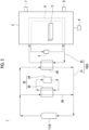
Fig. 3 is a schematic configuration diagram of a hydrogen production system according toEmbodiment 3 of the present disclosure. - Hereinafter, a hydrogen production system according to an embodiment of the present disclosure will be described with reference to the drawings. The embodiment described below shows one aspect of the present disclosure and is not to limit the present disclosure, and any change can be made within the scope of the technical idea of the present disclosure.
- As shown in
Fig. 1 , ahydrogen production system 1 according toEmbodiment 1 of the present disclosure includes acontainer 2 which accommodates ahydrogen compound member 3, aheating device 4 that heats an inside of thecontainer 2, acooling device 5 which cools the inside of thecontainer 2, and awater supply device 6 which supplies water into thecontainer 2. As described in an operation which will be described later, hydrogen or oxygen is generated in thecontainer 2, and ahydrogen release unit 7 and anoxygen release unit 8 through which hydrogen and oxygen are released from thecontainer 2, respectively, are provided on thecontainer 2. - When an element other than hydrogen (H) is defined as X, the
hydrogen compound member 3 has a two-dimensional arrangement of a hydrogen compound represented by a chemical formula XmHn, and a stoichiometric ratio m:n is 1:1 to 3:4 (for example, XH, XH2, XH3, XH4, X2H3, or X3H4). Although not limited, the element X is, for example, boron (B). - The
heating device 4 is for heating the inside of thecontainer 2, that is, thehydrogen compound member 3 accommodated in thecontainer 2. Theheating device 4 may be configured such that a heat medium comes into direct contact with thehydrogen compound member 3 by supplying the heat medium into thecontainer 2. However, hereinafter, theheating device 4 will be described as having a configuration in which thehydrogen compound member 3 accommodated in thecontainer 2 is heated by causing the heat medium to flow through aheat medium passage 9 such as a jacket or a passage provided to cover an outer surface of thecontainer 2 and exchanging heat between the heat medium and a gas in thecontainer 2. The heat medium is not particularly limited, but a liquid heat medium such as water or oil is preferably used. - The
heating device 4 includes a heatmedium circulation line 10 having one end connected to an inlet of theheat medium passage 9 and the other end connected to an outlet of theheat medium passage 9 to circulate the heat medium, and asunlight focusing device 11 which heats the heat medium by focusing and emitting sunlight to the heat medium which circulates through the heatmedium circulation line 10. The configuration of thesunlight focusing device 11 is not particularly limited, and for example, any type of device such as a parabolic trough, a solar power generation tower, and a parabolic dish can be used, but in consideration of a maximum heating temperature, cost, and the like, parabolic trough type device is preferable. - The
cooling device 5 is for cooling the inside of thecontainer 2, that is, thehydrogen compound member 3 accommodated in thecontainer 2. The configuration of thecooling device 5 is not particularly limited, and for example, a refrigerant type cooling device such as an air cooler or a water cooler can be used. In a case where thecooling device 5 is of a refrigerant type, a refrigerant such as cooling air or water may flow through theheat medium passage 9, or may be supplied into thecontainer 2. In addition, immediately after the heating of the inside of thecontainer 2 is completed, an outside temperature of thecontainer 2 is lower than an internal temperature of thecontainer 2, and therefore, if the inside of thecontainer 2 is opened to the outside of thecontainer 2, the inside of thecontainer 2 can be cooled. Accordingly, an on/off valve capable of opening and closing the inside of thecontainer 2 to the outside of thecontainer 2 can also be set as thecooling device 5. - The
water supply device 6 is for supplying a fluid containing liquid water, steam, or at least one of water or steam as a main component (hereinafter, simply referred to as "water" as a component meaning all of these) into thecontainer 2. If a temperature of the water is close to a cooling temperature of thecooling device 5, the inside of thecontainer 2 can be cooled by the supplied water, and in this case, thewater supply device 6 can also serve as thecooling device 5. - Next, an operation of the
hydrogen production system 1 according toEmbodiment 1 of the present disclosure will be described. Thehydrogen production system 1 operates to switch an operation of driving theheating device 4 and stopping thecooling device 5 and thewater supply device 6 to release hydrogen (hydrogen release operation) and an operation of stopping theheating device 4 and driving thecooling device 5 and thewater supply device 6 to store hydrogen (hydrogen storage operation) to each other. - First, the hydrogen release operation will be described. The
hydrogen compound member 3 accommodated in thecontainer 2 is in a state of storing hydrogen. In order to release hydrogen, theheating device 4 is driven. The heat medium is heated by irradiating the heat medium circulating through the heatmedium circulation line 10 with sunlight focused by thesunlight focusing device 11 by a pump (not shown) or the like. The heated heat medium exchanges heat with the gas in thecontainer 2 when flowing through theheat medium passage 9, so that thehydrogen compound member 3 accommodated in thecontainer 2 is heated. When a temperature of thehydrogen compound member 3 is in a range of about 150°C to about 300°C, hydrogen is released from thehydrogen compound member 3. The hydrogen released from thehydrogen compound member 3 is caused to flow out from thecontainer 2 through thehydrogen release unit 7, thereby collecting the hydrogen. - Next, the hydrogen storage operation will be described. By driving the
cooling device 5 in a state where theheating device 4 is stopped, a temperature of the inside of thecontainer 2 is controlled to be lower than about 150°C, preferably about 80°C or higher and lower than about 150°C. When thewater supply device 6 supplies water into thecontainer 2 in this state, the water is decomposed into hydrogen and oxygen in the presence of thehydrogen compound member 3, and hydrogen is absorbed in thehydrogen compound member 3. Accordingly, thehydrogen compound member 3 is in a state of storing hydrogen. The oxygen is retained in thecontainer 2, but the oxygen is caused to flow out from thecontainer 2 through theoxygen release unit 8, thereby collecting the oxygen. - As described above, in the
hydrogen production system 1 of the present disclosure, the heat medium heated by emitting the focused sunlight heats thehydrogen compound member 3 accommodated in thecontainer 2, and accordingly, the hydrogen can be produced with excellent thermal efficiency. - In
Embodiment 1, each of hydrogen and oxygen is released from thecontainer 2 through separate release unit, that is, thehydrogen release unit 7 and theoxygen release unit 8, but is not limited to this embodiment. Thehydrogen release unit 7 and theoxygen release unit 8 may be changed to one common release port, and this release port may be changed to a supply destination of hydrogen and oxygen. - Next, a hydrogen production system according to Embodiment 2 will be described. In the hydrogen production system according to
Embodiment 2, a heat storage unit which stores some of the heat of the heat medium heated by sunlight is added toEmbodiment 1. InEmbodiment 2, the same reference numerals are used for the same constituent elements ofEmbodiment 1 and the specific description is omitted. - As shown in
Fig. 2 , in thehydrogen production system 1 according toEmbodiment 2 of the present disclosure, the heat medium is configured with a first heat medium irradiated with sunlight by thesunlight focusing device 11, and a second heat medium for heating the inside of thecontainer 2. The first heat medium and the second heat medium may be the same fluid or different fluids. - The heat
medium circulation line 10 includes a first heatmedium circulation line 21 through which the first heat medium circulates, and a second heatmedium circulation line 22 through which the second heat medium circulates. Thehydrogen production system 1 includes afirst heat exchanger 20 which exchanges heat between the first heat medium which circulates through the first heatmedium circulation line 21 and a second heat medium which circulates through the second heatmedium circulation line 22. In addition, thehydrogen production system 1 includes aheat storage unit 23 capable of storing some of the heat of the first heat medium and releasing the stored heat to the first heat medium. Theheat storage unit 23 includes a heat storagemedium accommodation unit 24 which accommodates a heat storage medium, and asecond heat exchanger 25 which exchanges heat between the first heat medium and the heat storage medium which flows through abypass line 26 through which the first heat medium bypasses thefirst heat exchanger 20. The heat storage medium may be a fluid same as or different from the first heat medium or the second heat medium. Other configurations are the same as those inEmbodiment 1. - Next, an operation of the
hydrogen production system 1 according toEmbodiment 2 of the present disclosure will be described. The first heat medium is heated by irradiating the first heat medium circulating through the first heatmedium circulation line 21 with sunlight focused by thesunlight focusing device 11. In thefirst heat exchanger 20, the second heat medium is heated by exchanging heat between the first heat medium and the second heat medium. The second heat medium circulating through the second heatmedium circulation line 22 heats the inside of thecontainer 2 by exchanging heat with the gas in thecontainer 2 when flowing through theheat medium passage 9. Accordingly, thehydrogen compound member 3 in a state of storing hydrogen is heated so that the hydrogen is released from thehydrogen compound member 3. The operation of collecting the hydrogen released from thehydrogen compound member 3 is the same as that ofEmbodiment 1. - While the first heat medium circulates through the first heat
medium circulation line 21, some of the first heat medium flows through thebypass line 26 to bypass thefirst heat exchanger 20. The first heat medium flowing through thebypass line 26 exchanges heat with the heat storage medium in thesecond heat exchanger 25, so that some of the heat of the first heat medium is moved to the heat storage medium. By continuing this operation until sunset, the heat storage medium storing some of the heat of the first heat medium is stored in the heat storagemedium accommodation unit 24. - In
Embodiment 1, since the heat medium cannot be heated at night after sunset, the hydrogen release operation cannot be performed. However, inEmbodiment 2, the heat of the heat storage medium and the first heat medium are exchanged in thesecond heat exchanger 25 even at night, so that the heat stored in the heat storage medium can be moved to the first heat medium, thereby heating the first heat medium. The heated first heat medium and second heat medium exchange heat in thefirst heat exchanger 20 to heat the second heat medium, and thehydrogen compound member 3 is heated by the second heat medium, thereby releasing hydrogen from thehydrogen compound member 3. Such a hydrogen release operation is not limited to the night, and as long as the heat is stored in theheat storage unit 23, the hydrogen release operation can be performed even when an intensity of sunlight is weak such as when it is cloudy or rainy. - The hydrogen storage operation is performed in the same operation as in
Embodiment 1 by stopping theheating device 4 and driving thecooling device 5 and thewater supply device 6. - As described above, even when it is cloudy or rainy or even at night, the first heat medium and the second heat medium can be heated by releasing heat stored in the
heat storage unit 23 to the first heat medium, and accordingly, it is possible to produce hydrogen with excellent thermal efficiency regardless of the weather or time. - Next, a hydrogen production system according to
Embodiment 3 will be described. In the hydrogen production system according toEmbodiment 3, a configuration is changed to provide a plurality ofcontainers 2 accommodating thehydrogen compound member 3 thereby adjusting the number ofcontainers 2 for performing the hydrogen release operation according to the amount of heat from sunlight, compared toEmbodiment Embodiment 2 will be described asEmbodiment 3, butEmbodiment 3 can also be configured by making such changes toEmbodiment 1. InEmbodiment 2, the same reference numerals are used for the same constituent elements ofEmbodiment 3 and the specific description is omitted. - As shown in
Fig. 3 , in thehydrogen production system 1 according toEmbodiment 3 of the present disclosure, the plurality ofcontainers 2, for example, threecontainers hydrogen compound member 3 is accommodated in each container.Branch lines medium passages containers medium circulation line 22. Specifically, thebranch lines medium supply lines medium circulation line 22 and the other end connected to an inlet of each of the heatmedium passages medium return lines medium passages medium circulation line 22. - First on/off
valves medium supply lines valves medium return lines medium circulation line 22 to flow or not to flow through thebranch lines valves valves valves valves valves valves Embodiment 2. - An operation of heating the first heat medium with the sunlight focused by the
sunlight focusing device 11, an operation of heating the second heat medium with the heat of the first heat medium, and an operation of storing some of the heat of the first heat medium by theheat storage unit 23 are the same as those ofEmbodiment 2. The second heat medium circulating through the second heatmedium circulation line 22 flows through theheat medium passage 9a of thecontainer 2a by opening the first on/offvalve 33a and the second on/offvalve 34a, and thehydrogen compound member 3 accommodated in thecontainer 2a can be heated to release hydrogen. In the same manner, the hydrogen can be released from thehydrogen compound member 3 accommodated in thecontainer 2b by opening the first on/offvalve 33b and the second on/offvalve 34b, and the hydrogen can be released from thehydrogen compound member 3 accommodated in thecontainer 2c by opening the first on/offvalve 33c and the second on/offvalve 34c. - By adjusting the opening and closing of the first on/off
valves valves hydrogen compound member 3 accommodated in one container of the three containers, the release of hydrogen from thehydrogen compound member 3 accommodated in each of two containers of the three containers, and the release of hydrogen from thehydrogen compound member 3 accommodated in each of the three containers. That is, the amount of hydrogen released can be adjusted in three stages. This adjustment can be performed according to the amount of heat from the sunlight. Other operations are the same as those inEmbodiment 2. - As described above, since the number of
containers sunlight focusing device 11, it is possible to improve operating efficiency of thehydrogen production system 1. - The mass of the
hydrogen compound member 3 accommodated in each of at least two containers of thecontainers hydrogen compound member 3 accommodated in each of thecontainers Embodiment 3, the amount of hydrogen released can be adjusted in three stages. However, according to such a modification example, the amount of hydrogen production can be adjusted in stages more than three stages according to the amount of focused sunlight. - For example, the contents described in each embodiment are understood as follows.
-
- [1] A hydrogen production system according to one aspect including
- at least one container (2) which accommodates a hydrogen compound member (3),
- a heating device (4) which heats an inside of the at least one container (2) by a heat medium,
- a cooling device (5) which cools the inside of the at least one container (2), and
- a water supply device (6) which supplies water into the at least one container (2),
- in which the heating device (4) includes a sunlight focusing device (11) which heats the heat medium by focusing sunlight and emitting to the heat medium.
- [2] The hydrogen production system of another aspect according to [1], further including
- a heat storage unit (23),
- in which the heat storage unit (23) stores some of heat of the heat medium and releases the heat stored in the heat storage unit to the heat medium.
- [3] The hydrogen production system of still another aspect according to [2],
in which the heat medium includes- a first heat medium irradiated with sunlight by the sunlight focusing device (11), and
- a second heat medium which is heated by exchanging heat with the first heat medium and heats the inside of the at least one container (2),
- the hydrogen production system (1) includes a first heat exchanger (20) which exchanges heat between the first heat medium and the second heat medium, and
- the heat storage unit (23) includes
- a heat storage medium accommodation unit (24) which accommodates a heat storage medium, and
- a second heat exchanger (25) which exchanges heat between the first heat medium and the heat storage medium.
- [4] The hydrogen production system of still another aspect according to any one of [1] to [3],
- in which the at least one container (2) includes a plurality of containers (2a, 2b, 2c), and
- the hydrogen production system (1) includes
- a heat medium circulation line (10) through which the heat medium flows,
- a branch line (30a, 30b, 30c) which branches from the heat medium circulation line (10) and joins the heat medium circulation line (10) again through each container (2a, 2b, 2c), and
- a switching unit (first on/off
valves valves
- [5] The hydrogen production system of still another aspect according to [4],
in which a mass of the hydrogen compound member (3) accommodated in each of at least two containers of the plurality of containers (2a, 2b, 2c) is different.
According to such a configuration, the amount of hydrogen production can be finely adjusted according to the amount of heat of the focused sunlight. - [6] The hydrogen production system of still another aspect according to any one of [1] to [5],
in which, when an element other than hydrogen is defined as X, the hydrogen compound member (3) has a two-dimensional arrangement of a hydrogen compound represented by a chemical formula XmHn, and a stoichiometric ratio m:n is 1:1 to 3:4.
According to such a configuration, hydrogen can be stored and released. - [7] The hydrogen production system of still another aspect according to [6],
in which the element X is boron.
According to such a configuration, hydrogen can be stored and released. -
- 1 Hydrogen production system
- 2, 2a, 2b, 2c Container
- 3 Hydrogen compound member
- 4 Heating device
- 5 Cooling device
- 6 Water supply device
- 10 Heat medium circulation line
- 11 Sunlight focusing device
- 20 First heat exchanger
- 23 Heat storage unit
- 24 Heat storage medium accommodation unit
- 25 Second heat exchanger
- 30a, 30b, 30c Branch line
- 33a, 33b, 33c First on/off valve (switching unit)
- 34a, 34b, 34c Second on/off valve (switching unit)
Claims (7)
- A hydrogen production system comprising:at least one container which accommodates a hydrogen compound member;a heating device which heats an inside of the at least one container by a heat medium;a cooling device which cools the inside of the at least one container; anda water supply device which supplies water into the at least one container,wherein the heating device includes a sunlight focusing device which heats the heat medium by focusing sunlight and emitting to the heat medium.
- The hydrogen production system according to claim 1, further comprising:a heat storage unit,wherein the heat storage unit stores some of heat of the heat medium and releases the heat stored in the heat storage unit to the heat medium.
- The hydrogen production system according to claim 2,
wherein the heat medium includesa first heat medium irradiated with sunlight by the sunlight focusing device, anda second heat medium which is heated by exchanging heat with the first heat medium and heats the inside of the at least one container,the hydrogen production system includes a first heat exchanger which exchanges heat between the first heat medium and the second heat medium, andthe heat storage unit includesa heat storage medium accommodation unit which accommodates a heat storage medium, anda second heat exchanger which exchanges heat between the first heat medium and the heat storage medium. - The hydrogen production system according to any one of claims 1 to 3,wherein the at least one container includes a plurality of containers, andthe hydrogen production system includesa heat medium circulation line through which the heat medium circulates,a branch line which branches from the heat medium circulation line and joins the flowing through circulation line again through each container, anda switching unit which is provided on each branch line and switches between flowing of the heat medium through the branch line and not allowing the heat medium to flow through the branch line.
- The hydrogen production system according to claim 4,
wherein a mass of the hydrogen compound member accommodated in each of at least two containers of the plurality of containers is different. - The hydrogen production system according to any one of claims 1 to 3,
wherein, when an element other than hydrogen is defined as X, the hydrogen compound member has a two-dimensional arrangement of a hydrogen compound represented by a chemical formula XmHn, and a stoichiometric ratio m:n is 1:1 to 3:4. - The hydrogen production system according to claim 6,
wherein the element X is boron.
Applications Claiming Priority (2)
| Application Number | Priority Date | Filing Date | Title |
|---|---|---|---|
| JP2021136409A JP7386211B2 (en) | 2021-08-24 | 2021-08-24 | Hydrogen production system |
| PCT/JP2022/029300 WO2023026768A1 (en) | 2021-08-24 | 2022-07-29 | Hydrogen production system |
Publications (2)
| Publication Number | Publication Date |
|---|---|
| EP4357299A1 true EP4357299A1 (en) | 2024-04-24 |
| EP4357299A4 EP4357299A4 (en) | 2025-05-21 |
Family
ID=85323019
Family Applications (1)
| Application Number | Title | Priority Date | Filing Date |
|---|---|---|---|
| EP22861059.8A Pending EP4357299A4 (en) | 2021-08-24 | 2022-07-29 | HYDROGEN PRODUCTION SYSTEM |
Country Status (6)
| Country | Link |
|---|---|
| US (1) | US20240308842A1 (en) |
| EP (1) | EP4357299A4 (en) |
| JP (1) | JP7386211B2 (en) |
| CN (1) | CN117580798A (en) |
| AU (1) | AU2022335839B2 (en) |
| WO (1) | WO2023026768A1 (en) |
Families Citing this family (1)
| Publication number | Priority date | Publication date | Assignee | Title |
|---|---|---|---|---|
| TWI915672B (en) * | 2023-08-30 | 2026-02-21 | 啓聖 王 | Green hydrogen manufacturing system and its implementation method |
Family Cites Families (18)
| Publication number | Priority date | Publication date | Assignee | Title |
|---|---|---|---|---|
| JP4843845B2 (en) * | 2000-07-03 | 2011-12-21 | トヨタ自動車株式会社 | Fuel cell system and control method thereof |
| US7951349B2 (en) * | 2006-05-08 | 2011-05-31 | The California Institute Of Technology | Method and system for storing and generating hydrogen |
| US20080138675A1 (en) * | 2006-12-11 | 2008-06-12 | Jang Bor Z | Hydrogen generation and storage method for personal transportation applications |
| EP2294002A4 (en) * | 2008-06-25 | 2012-12-26 | Hydrogen Generation Inc | IMPROVED PROCESS FOR HYDROGEN PRODUCTION |
| JP2010017700A (en) * | 2008-07-14 | 2010-01-28 | Techno Bank:Kk | Method for using waste material of lightweight structural material |
| EP2433903B1 (en) * | 2009-05-21 | 2016-04-20 | Panasonic Intellectual Property Management Co., Ltd. | Hydrogen generation system and hot water production system |
| AU2010201979A1 (en) * | 2009-06-16 | 2011-01-06 | Solar Fusion Power Pty Ltd | A solar energy collection and storage system |
| US20110100356A1 (en) * | 2009-10-13 | 2011-05-05 | Wayne Thomas Bliesner | Reversible hydride thermal energy storage cell optimized for solar applications |
| JP2013126948A (en) * | 2013-03-25 | 2013-06-27 | Taane Co Ltd | Hydrogen generation method and hydrogen generator |
| JP5917591B2 (en) | 2014-04-17 | 2016-05-18 | 三菱日立パワーシステムズ株式会社 | Hydrogen gas generation system |
| WO2018074518A1 (en) * | 2016-10-18 | 2018-04-26 | 国立大学法人筑波大学 | Sheet containing two-dimensional borohydride and production method for sheet containing two-dimensional boron compound |
| JP6812252B2 (en) * | 2017-01-27 | 2021-01-13 | 関西電力株式会社 | Hydrogen production equipment, power generation system and hydrogen production method |
| JP7079932B2 (en) * | 2018-06-22 | 2022-06-03 | 国立大学法人東京工業大学 | Hydrogen generation method, hydrogen generation system and fuel cell system |
| CN110260535B (en) * | 2019-05-15 | 2020-11-10 | 西安交通大学 | Solar continuous baking system and method |
| JP7164847B2 (en) | 2020-02-28 | 2022-11-02 | 日本特殊陶業株式会社 | piezoelectric actuator |
| JP7354051B2 (en) * | 2020-04-13 | 2023-10-02 | 三菱重工業株式会社 | Hydrogen release/storage systems, hydrogen release/storage methods, ammonia production equipment, gas turbines, fuel cells, and steel plants |
| JP7354050B2 (en) * | 2020-04-13 | 2023-10-02 | 三菱重工業株式会社 | Hydrogen release/storage system, hydrogen release/storage method, hydrogen release/storage device, ammonia production device, gas turbine, fuel cell, and steelworks |
| CN112344572A (en) * | 2020-09-23 | 2021-02-09 | 广东省科学院稀有金属研究所 | Hydride heat storage system and method for direct illumination heating |
-
2021
- 2021-08-24 JP JP2021136409A patent/JP7386211B2/en active Active
-
2022
- 2022-07-29 WO PCT/JP2022/029300 patent/WO2023026768A1/en not_active Ceased
- 2022-07-29 EP EP22861059.8A patent/EP4357299A4/en active Pending
- 2022-07-29 CN CN202280045593.6A patent/CN117580798A/en active Pending
- 2022-07-29 US US18/576,305 patent/US20240308842A1/en active Pending
- 2022-07-29 AU AU2022335839A patent/AU2022335839B2/en active Active
Also Published As
| Publication number | Publication date |
|---|---|
| JP7386211B2 (en) | 2023-11-24 |
| CN117580798A (en) | 2024-02-20 |
| WO2023026768A1 (en) | 2023-03-02 |
| AU2022335839A1 (en) | 2024-02-01 |
| AU2022335839B2 (en) | 2025-10-02 |
| US20240308842A1 (en) | 2024-09-19 |
| JP2023030977A (en) | 2023-03-08 |
| EP4357299A4 (en) | 2025-05-21 |
Similar Documents
| Publication | Publication Date | Title |
|---|---|---|
| US9609811B2 (en) | Method and system for utilizing heat in a plant or animal growing device, and greenhouse | |
| US6644030B2 (en) | Cooling systems and methods of cooling | |
| CN117239284B (en) | Energy storage device, photovoltaic storage system and charging network | |
| US20130306058A1 (en) | Steam generation system | |
| WO2020116168A1 (en) | Solar thermal power generation system | |
| US20240308842A1 (en) | Hydrogen production system | |
| CN117239285A (en) | An energy storage device, optical storage system and charging network | |
| WO2020116167A1 (en) | Solar thermal power generation system | |
| WO2005045954A2 (en) | Freeze tolerant fuel cell power plant with a direct contact heat exchanger | |
| JP2018527699A (en) | Fuel cell system | |
| CN117790978A (en) | Thermal management device and control method thereof | |
| JP2018147731A (en) | Fuel cell system | |
| JP6997714B2 (en) | Power generation system | |
| JP2004311347A (en) | Fuel cell cooling system | |
| RU2602708C2 (en) | Apparatus for generating solar energy and an external steam source of additional electric power | |
| CN118412493A (en) | Fuel cell cold start system and control method | |
| JP2004020081A (en) | Power generation heat utilization system | |
| JP2022548334A (en) | Fuel cell system with combined fuel vaporization and cathode gas heater unit and method of use and operation | |
| JP2013057435A (en) | Heat supply system | |
| WO2018105205A1 (en) | Fuel cell system | |
| CN214753856U (en) | Heat dissipation device, fuel cell auxiliary system heat dissipation device and fuel cell system | |
| KR20210057381A (en) | Smart farm system | |
| KR20240041090A (en) | Electric Propulsion System using Low Flash Point Fuel Hybrid Cooling System for Ships | |
| KR20240058267A (en) | Hybrid heat storage system using fuel cell waste heat and solar heat collection | |
| KR101309196B1 (en) | A heating system of vehicle |
Legal Events
| Date | Code | Title | Description |
|---|---|---|---|
| STAA | Information on the status of an ep patent application or granted ep patent |
Free format text: STATUS: THE INTERNATIONAL PUBLICATION HAS BEEN MADE |
|
| PUAI | Public reference made under article 153(3) epc to a published international application that has entered the european phase |
Free format text: ORIGINAL CODE: 0009012 |
|
| STAA | Information on the status of an ep patent application or granted ep patent |
Free format text: STATUS: REQUEST FOR EXAMINATION WAS MADE |
|
| 17P | Request for examination filed |
Effective date: 20240116 |
|
| AK | Designated contracting states |
Kind code of ref document: A1 Designated state(s): AL AT BE BG CH CY CZ DE DK EE ES FI FR GB GR HR HU IE IS IT LI LT LU LV MC MK MT NL NO PL PT RO RS SE SI SK SM TR |
|
| DAV | Request for validation of the european patent (deleted) | ||
| DAX | Request for extension of the european patent (deleted) | ||
| REG | Reference to a national code |
Ref country code: DE Ref legal event code: R079 Free format text: PREVIOUS MAIN CLASS: C01B0003000000 Ipc: B01J0007000000 |
|
| A4 | Supplementary search report drawn up and despatched |
Effective date: 20250422 |
|
| RIC1 | Information provided on ipc code assigned before grant |
Ipc: B01J 19/12 20060101ALN20250414BHEP Ipc: B01J 6/00 20060101ALN20250414BHEP Ipc: B01D 1/00 20060101ALN20250414BHEP Ipc: C01B 3/00 20060101ALI20250414BHEP Ipc: C01B 3/04 20060101ALI20250414BHEP Ipc: B01J 7/00 20060101AFI20250414BHEP |