EP4357244A1 - Flight vehicle operation management system and flight vehicle operation management method - Google Patents
Flight vehicle operation management system and flight vehicle operation management method Download PDFInfo
- Publication number
- EP4357244A1 EP4357244A1 EP22824691.4A EP22824691A EP4357244A1 EP 4357244 A1 EP4357244 A1 EP 4357244A1 EP 22824691 A EP22824691 A EP 22824691A EP 4357244 A1 EP4357244 A1 EP 4357244A1
- Authority
- EP
- European Patent Office
- Prior art keywords
- flight vehicle
- region
- flight
- layered
- operation management
- Prior art date
- Legal status (The legal status is an assumption and is not a legal conclusion. Google has not performed a legal analysis and makes no representation as to the accuracy of the status listed.)
- Pending
Links
Images







Classifications
-
- G—PHYSICS
- G08—SIGNALLING
- G08G—TRAFFIC CONTROL SYSTEMS
- G08G5/00—Traffic control systems for aircraft
- G08G5/20—Arrangements for acquiring, generating, sharing or displaying traffic information
- G08G5/26—Transmission of traffic-related information between aircraft and ground stations
-
- G—PHYSICS
- G08—SIGNALLING
- G08G—TRAFFIC CONTROL SYSTEMS
- G08G5/00—Traffic control systems for aircraft
- G08G5/20—Arrangements for acquiring, generating, sharing or displaying traffic information
- G08G5/22—Arrangements for acquiring, generating, sharing or displaying traffic information located on the ground
-
- G—PHYSICS
- G08—SIGNALLING
- G08G—TRAFFIC CONTROL SYSTEMS
- G08G5/00—Traffic control systems for aircraft
- G08G5/50—Navigation or guidance aids
- G08G5/52—Navigation or guidance aids for take-off
-
- G—PHYSICS
- G08—SIGNALLING
- G08G—TRAFFIC CONTROL SYSTEMS
- G08G5/00—Traffic control systems for aircraft
- G08G5/50—Navigation or guidance aids
- G08G5/54—Navigation or guidance aids for approach or landing
-
- G—PHYSICS
- G08—SIGNALLING
- G08G—TRAFFIC CONTROL SYSTEMS
- G08G5/00—Traffic control systems for aircraft
- G08G5/50—Navigation or guidance aids
- G08G5/55—Navigation or guidance aids for a single aircraft
-
- G—PHYSICS
- G08—SIGNALLING
- G08G—TRAFFIC CONTROL SYSTEMS
- G08G5/00—Traffic control systems for aircraft
- G08G5/50—Navigation or guidance aids
- G08G5/56—Navigation or guidance aids for two or more aircraft
-
- G—PHYSICS
- G08—SIGNALLING
- G08G—TRAFFIC CONTROL SYSTEMS
- G08G5/00—Traffic control systems for aircraft
- G08G5/50—Navigation or guidance aids
- G08G5/57—Navigation or guidance aids for unmanned aircraft
Definitions
- the present invention relates to a flight vehicle operation management system and a flight vehicle operation management method for a flight vehicle such as an aircraft.
- an eVTOL electric vertical takeoff and landing aircraft
- the electric vertical takeoff and landing aircraft is expected to solve various traffic problems such as reduction of traffic congestion and environmental load in urban areas, and securing of transportation means to underpopulated areas.
- PTL 1 discloses a technique of setting a partition in which a part of a landing area is virtually divided as a landing area for the purpose of efficiently using the landing area for a flight vehicle such as a drone, and performing landing processing in the landing area.
- PTL 1 proposes a method for efficiently using a takeoff and landing area assuming a state in which a plurality of flight vehicles fly into a takeoff and landing area assuming an airport.
- a high frequency of operation installation of the airport in a city, and the like can also be considered, and thus there is a possibility that a sufficient region cannot be secured. Therefore, there are few flight vehicles that can stand by above the airport when flight frequency increases, and not only utilization efficiency of the airport decreases, but also flexible flight management such as changing a landing order according to a degree of urgency cannot be performed.
- an object of the present invention is to provide a flight vehicle operation management system and a flight vehicle operation management method for an airport, the system and the method capable of increasing the utilization efficiency of the airport at the airport where a large number of flight vehicles having a vertical takeoff and landing function to take off and land.
- the present invention provides "a flight vehicle operation management system that manages flight-path planning and takeoff and landing of a flight vehicle at an airport including a plurality of airport aprons, in which the flight vehicle operation management system sets a layered region including at least one or more layers above the airport, and an occupied region around the flight vehicle, and the occupied region is set in the layered region in which the flight vehicle flies and in at least one of layered regions vertically adjacent to the layered region".
- the present invention provides "a flight vehicle operation management method in an airport including an airport apron, the flight vehicle operation management method including: setting a layered region including at least one or more layers above the airport to allow a flight vehicle to move in the layered region and take off and land; and setting an occupied region around the flight vehicle in the layered region, in which the occupied region is set in the layered region in which the flight vehicle flies and in at least one of layered regions vertically adjacent to the layered region".
- a flight vehicle operation management system and a flight vehicle control system capable of efficiently and safely taking off and landing a plurality of flight vehicles at an airport.
- FIG. 1 is a conceptual diagram illustrating a relationship between a flight vehicle, an airport, a layered region of the airport, and an occupied region of the flight vehicle according to a first embodiment of the present invention.
- FIG. 1 illustrates a state in which flight vehicles F (F1 to F4) is capable of vertical takeoff and landing with a plurality of rotor blades and are flying into an airport 5 at the same time.
- the flight vehicles F are used for applications such as boarding of a user, carrying of luggage, and photographing of aerial photographs.
- the flight vehicle F includes a flight vehicle control device 200 that controls flight of the flight vehicle F described later with reference to FIG. 2 inside the flight vehicle F.
- the airport 5 includes a plurality of airport aprons A (Aa, Ab) where the flight vehicles F take off and land, a control facility 8 that manages takeoff and landing in the airport, and an aerial monitoring unit 9 including a sensor that monitors a position and a state of the flight vehicle F above the airport 5.
- a flight vehicle operation management system 100 is installed in the control facility 8, and manages takeoff and landing on the basis of a state of the airport apron A of the airport 5, surrounding weather conditions, and the state of the flight vehicle F.
- the flight vehicle operation management system 100 of the present invention sets layered regions R (Ra to Rd) which are layered virtual regions above the airport 5.
- the layered region R is obtained by dividing a sky region of the airport 5 into a plurality of layers, and is set as the sky region of the airport 5.
- the layered regions R for example, four layers of R1, R2, R3, and R4 are sequentially formed in ascending order of height in a height direction.
- the flight vehicle F for example, F3 sequentially passes through the layers R1, R2, and R3 in the layered region from the airport apron Aa, and starts navigation from R4 toward a destination.
- R1 as a lowermost layer is to be referred to as an aircraft parking layer for parking the flight vehicle F
- R4 as an uppermost layer is to be referred to as a takeoff and landing layer since it is an entrance for entering and exiting the airport apron
- R2 and R4 are layers that allow the flight vehicle F to move in a horizontal direction, and play a role as a standby layer that allows other flight vehicles F to take off and land preferentially by allowing the flight vehicle F to move in the horizontal direction.
- the layered regions R are set above the airport 5 according to an altitude by the flight vehicle operation management system 100, and in which region the flight vehicle is flying is grasped using information of the flight vehicle operation management system 100 and the flight vehicle control system 200.
- occupied regions O (Oa to Od) of the flight vehicles are set around the flight vehicles F (F1 to F4) that have flown into the airport 5.
- the occupied region O has a three-dimensional shape obtained by vertically extending a plane wider in the horizontal direction than an outer edge of, for example, F3 as a flight vehicle, and occupies in a vertical direction at least a region in which the flight vehicle F3 is currently flying.
- an R2 layer among the layered regions R is an occupied region Oc2 (the number (2) indicates a suffix (in this case, 2) of the layered region R) in which the flight vehicle F3 occupies in the vertical direction a region in which the flight vehicle F3 is currently flying.
- the occupied region Oc is set including the layered region R2 in which the flight vehicle F3 is currently flying and occupied regions Oc1 and Oc3 set in the layered regions R1 and R3 vertically adjacent to the layered region R2.
- the occupied region O is described as a tubular shape here, the occupied region O may be set as a rectangular parallelepiped or the like.
- the flight vehicles F (F1 to F4) flying into the airport 5 descend along flight paths set inside the occupied regions O, land on the airport aprons Aa and Ab, and take off.
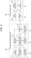
- FIG. 2 is a block diagram illustrating a configuration example of the flight vehicle operation management system 100 and the flight vehicle control system 200 according to the first embodiment of the present invention.
- the flight vehicle operation management system 100 includes an aerial monitoring unit 101 described above, a flight vehicle detection unit 102 that detects the position, state, and the like of the flight vehicle, a control information exchange unit 103 that acquires information of a flight vehicle flying in another airport or outside the airport and transmits information of the flight vehicle present in the airport, a takeoff and landing determination unit 104 that determines takeoff and landing of the flight vehicle in the airport, a port information acquisition unit 105 that acquires airport peripheral information such as space availability of the airport apron, climate (wind, wind and rain, and the like), the number of passengers, and the like, an occupied region setting unit 106 that sets the occupied region O of the flight vehicle, a takeoff and landing path design unit 107 that generates the flight path in the occupied region of the flight vehicle, and a communication unit 108 that transmits a takeoff and landing path and a position of the occupied region O to the flight vehicle control system 200, and receives surrounding conditions based on a sensor of the flight vehicle, and
- the flight vehicle control system 200 installed in the flight vehicle includes a communication unit 201 on the flight vehicle control system 200 side that exchanges signals with the communication unit 108 of the flight vehicle operation management system 100, a state monitoring unit 202 that monitors a posture, a position, a battery charge amount, a state of a device and the like of the flight vehicle, a peripheral monitoring unit 203 including a sensor that detects another flight vehicle, an obstacle, and the like around the flight vehicle, and a flight control unit 204 that controls a flight of the flight vehicle based on the state of the flight vehicle obtained by the state monitoring unit 202 based on takeoff and landing path information and information on the occupied region O received by the communication unit 201, and information around the flight vehicle obtained by the peripheral monitoring unit.
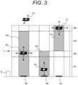
- FIG. 3 is a schematic diagram of a cross-sectional view in a certain vertical plane of the airport 5 as viewed from right beside.
- the layered regions R and the occupied regions O set above the airport 5 will be described with reference to FIG. 3 .
- the layered regions R are set above the airport 5.
- An upper end layer R4 of the layered regions R is preferably set based on a height at which the flight vehicle F can fly or the like.
- FIG. 3 illustrates an example in which the occupied region is not set because a flight vehicle F5 is out of a management region by the layered region R.
- regions in the height direction of the airport aprons A are the layered regions R, and portions with background colors in the layered regions represent the occupied regions O (Oc, Oa, and Ob) respectively set for the flight vehicles F (F1, F3, and F4). Further, arrows illustrated on the flight vehicles F (F1, F3, and F4) indicate movable directions of the flight vehicles.
- FIG. 4 is a schematic diagram illustrating a relationship between height setting of the layered region and an airflow generated by the flight vehicle.
- FIG. 4 illustrates the flight vehicles F1 and F2 flying in upper and lower layered regions R1 and R3 with, for example, R2 (indicated by gray hatching) as one layer region of the layered regions interposed therebetween.
- R2 indicated by gray hatching
- FIG. 4 a part of flow of the airflow generated by a fan of the flight vehicle F1 is indicated by a streamline 110.
- a height of the one layer region R2 of the layered regions is preferably set higher than an influence range of the downward airflow as illustrated in FIG. 4 .
- FIG. 4 illustrates a method of determining the height on the basis of the influence range of the airflow generated by the fan of the flight vehicle, and in addition to this, the height can be determined on the basis of an expected movement amount until recovery after a partial failure of the flight vehicle, disturbance such as an expected weather change, an movement amount of the flight vehicle required to avoid an intruder such as a bird, and the like.
- the layered regions R1, R2, R3, and R4 have different roles depending on, for example, the height and are configured by transition regions R1 and R3 and standby regions R2 and R4.
- the position of the occupied region O cannot be moved when the flight vehicle F flies in these regions, and when the flight vehicle F flies in the standby regions R2 and R4, the position of the occupied region O can be changed in the horizontal direction together with the flight vehicle F while avoiding contact with other occupied regions O.
- the occupied region O of the flight vehicle F is set as a three-dimensional occupied region O around the flight vehicle F.
- the occupied region O has a three-dimensional shape obtained by vertically extending a plane set wider than the outer edge of the flight vehicle F in the horizontal direction.
- the occupied region O is preferably extended over regions (transition regions R1 and R3) vertically adjacent to the region (standby region R2) in which the flight vehicle F flies.
- a movement path in the vertical direction is basically designed in the transition regions R1 and R3, and a movement path in the horizontal direction is designed in the standby regions R2 and R4.
- movement in the horizontal direction is designed as illustrated in FIG. 5 .
- FIG. 5 is a schematic diagram of the occupied region O in contact with a plane of the upper end of the standby region R2 indicated by an arrow I in FIG. 3 .
- the flight vehicles F1 and F3 flying in the standby region can horizontally move 114 and 116 together with the occupied regions Oa and Oc.
- the occupied region Od of the flight vehicle F2 is not allowed to horizontally move because the flight vehicle is flying in the transition region.
- FIG. 5 illustrates movement loci 114 and 116 when the flight vehicles F1 and F3 and the occupied regions Oa and Oc move.
- the locus of the occupied region O at the time of movement can be designed not to come into contact with another occupied region O and another movement locus for each control cycle.
- the occupied region Oa of the flight vehicle F3 is at a vertical position that is not in contact with the occupied region Od, and thus the occupied region Oa and the movement locus 116 may be designed to be allowed to contact and overlap with each other although the path is not in contact with another path in this drawing.
- the layered regions are preferably set such that the transition regions R1 and R3 are higher than the standby regions R2 and R4. Since the standby regions R1 and R3 require path design in the horizontal direction and the vertical direction, an increase in processing load or the like is assumed, and the transition regions R1 and R3 are preferably set high in order to shorten takeoff and landing time.
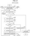
- FIG. 6 is a flowchart illustrating the operation of the flight vehicle operation management system 100 according to the first embodiment of the present invention
- FIG. 7 is a flowchart illustrating the operation of the flight vehicle control system 200.
- FIGS. 6 and 7 a description will be given assuming a landing time in a takeoff and landing operation.
- the flight vehicle F1 of the plurality of flight vehicles F1 to F4 illustrated in FIG. 3 will be described as an example.
- FIGS. 6 and 7 Flows of FIGS. 6 and 7 are respectively operated in the flight vehicle operation management system 100 and the flight vehicle control system 200, and there is a relationship in which signals are exchanged at an appropriate timing to affect each other. Therefore, in the following description, mutual operations will be described in chronological order.
- a first stage of FIGS. 6 and 7 is a state in which the flight vehicle F1 is approaching above the airport.
- processing step S301 of the flight vehicle operation management system 100 installed in the airport 5 in FIG. 6 when the flight vehicle arrives above the airport, permission to land is determined, and a landing permission signal Sg1 is notified to the flight vehicle F1.
- step S301 the flight vehicle F1 arrives above the airport 5, and the flight vehicle detection unit 104 detects the flight vehicle F1 on the basis of aerial information of the aerial monitoring unit 101 installed in the airport 5 and position information of the flight vehicle F1 of the flight vehicle control system 200 from the communication unit 108.
- the takeoff and landing determination unit 104 determines landing on the airport 5 by using situation above the airport 5 by the aerial monitoring unit 101, a flight plan of the flight vehicle F1 and flight information of other flight vehicles received by the control information exchange unit 103, airport apron availability information of the airport 5 of the port information acquisition unit 105, surrounding weather information, airport information such as the presence or absence of emergency information, a landing application signal Sg0 from the flight vehicle control system 200 of the flight vehicle F1 obtained by the communication unit 108, and the like, and notifies the flight vehicle F1 of the landing permission signal Sg1 by using the communication unit 108. Thereafter, the process proceeds to step S302.
- processing step S401 of the flight vehicle control system 200 on the flight vehicle side the flight vehicle F1 arrives above the airport 5 and transitions to a landing state.
- step S401 in FIG. 7 when the flight vehicle F1 arrives above the airport 5, it is determined that the flight vehicle F1 has entered the region of the airport 5, and the landing application signal Sg0 is transmitted. Further, as described above, the flight vehicle F1 transitions to the landing state by receiving the landing permission signal Sg1 from the flight vehicle operation management system 100.
- step S402 the state monitoring unit 202 installed in the flight vehicle F1 collects, for example, internal information such as the position, attitude, battery state of the flight vehicle F1, and control state of each device, and external information such as flight vehicles other than the flight vehicle F1 and obstacles acquired by the peripheral monitoring unit 203, and transmits the collected information to the flight vehicle operation management system 100 on the airport 5 side via the communication unit 201 as a flight vehicle information signal Sg2.
- processing in step S402 is processing continuously executed in a flight state.
- step S403 it is determined whether it is the flight state, and when it is the flight state, processing in step S404 is continuously executed.
- step S302 of the flight vehicle operation management system 100 installed in the airport 5 in FIG. 6 the flight vehicle information signal Sg2 transmitted in step S402 in FIG. 7 is received, and the position of the flight vehicle is detected.
- the flight vehicle detection unit 102 detects the position information of the flight vehicle F1 on the basis of the aerial information obtained by the aerial monitoring unit 101 installed in the airport 5 and the position information of the flight vehicle F1 included in the flight vehicle information signal Sg2 transmitted from the flight vehicle control system 200 obtained by the communication unit 108. Thereafter, the process proceeds to step S303.
- step S303 the takeoff and landing determination unit 104 determines whether the flight vehicle F1 is in the flight state or the landing state on the basis of the position information of the flight vehicle F1 and the state information of the flight vehicle F1. The process proceeds to step S304 in the case of the flight state, and the process proceeds to step S311 in the case of the landing state.
- step S304 an airport apron designated by the flight vehicle operation management system 100 of the airport 5 is determined as a landing position. This parking position may be changed due to availability of the airport apron, congestion in the airport, occurrence of an emergency, or the like. Thereafter, the process proceeds to step S305.
- step S305 the occupied region setting unit 106 sets the occupied region O around the flight vehicle F1.
- a three-dimensional body obtained by vertically extending a plane having an edge horizontally outward from the edge of the flight vehicle is set as the occupied region O. Thereafter, the process proceeds to step S306.
- step S306 the takeoff and landing path design unit 107 determines where in the layered region R the flight vehicle F1 is flying on the basis of the position information of the flight vehicle F1. For example, determination is made by comparing a height of the flight vehicle F1 with a height of each region of the layered regions R set above the airport 5. If the flight vehicle is flying in the standby region, the process proceeds to step S307, and if the flight vehicle is flying in the transition region, the process proceeds to step S309.
- step S307 the takeoff and landing path design unit 107 designs a horizontal flight path in the standby region of the flight vehicle F1.
- the above-described method can be used as a method of designing the horizontal flight path. Thereafter, the process proceeds to step S308.
- step S308 the takeoff and landing path design unit 107 designs a flight path in the vertical direction of the flight vehicle F1.
- the path can be designed so as to have a constant descent speed that does not damage cargo. Thereafter, the process proceeds to step S309.
- step S309 since the flight vehicle F1 flies in the transition region, the takeoff and landing path design unit 107 does not allow the path design in the horizontal direction.
- the flight path in the vertical direction can be designed so as to have, for example, the constant descent speed that does not damage the cargo. Thereafter, the process proceeds to step S310.
- step S310 the communication unit 108 transmits information Sg3 on the occupied region O and the flight path to the flight vehicle control system 200 of the flight vehicle F1. Thereafter, the process returns to step S302, and the above processing is repeated.
- step S311 when the flight vehicle F1 lands, the communication unit 108 transmits landing completion information Sg4 to the flight vehicle control system 200 of the flight vehicle F1, and ends processing at the time of landing.
- step S403 it has been determined whether the flight vehicle F1 is in the flight state or the landing state on the basis of the position information of the flight vehicle F1 and the state information of the flight vehicle F1, and it has been confirmed that the flight vehicle F1 is in the flight state.
- step S404 of FIG. 7 the flight unit F1 in flight acquires the information Sg3 on the occupied region O and a path plan assigned to the flight vehicle F1 from the flight vehicle operation management system 100 installed on the airport 5 side by the state monitoring unit 202.
- step S405 the flight control unit 204 detects an obstacle around the flight vehicle F1 on the basis of information of the state monitoring unit 202, and checks the presence or absence of the obstacle on the path assigned from the flight vehicle operation management system 100. If there is no obstacle, the process proceeds to step S407, and if there is the obstacle, the process proceeds to step S406.
- step S406 the flight control unit 204 detects a position of the obstacle on the basis of the information of the state monitoring unit 202, and corrects the movement path transmitted from the flight vehicle operation management system 100 so as to avoid the obstacle. At this time, when an avoidance path is designed in the occupied region O, contact with another flight vehicle can be avoided.
- step S405 If it is determined in step S405 that there is no obstacle or if the path is corrected in step S406, the flight is performed according to these pieces of path information in step S407. Thereafter, the process proceeds to step S402, and is repeated until landing is determined in S403.
- step S408 the landing completion information of the flight vehicle F1 is transmitted to the flight vehicle operation management system via the communication unit 201.
- a landing operation of the flight vehicle F1 is performed as described above.
- the utilization efficiency above the airport 5 is improved, and even when the airport is located in a narrow land, it is possible to stand by in the sky.
- FIGS. 1 and 3 illustrate horizontal widths of the occupied regions O of the plurality of flight vehicles as being the same, but each of the widths may be changed according to a size and performance of the flight vehicle and the climate around the airport 5.
- the height of the layered region R may also be changed according to the climate around the airport 5.
- FIGS. 1 and 3 illustrate an example in which the flight vehicle F1 occupies the region in which the flight vehicle F1 flies and regions above and below the region, however, as illustrated in FIG. 8 , even if the flight vehicle F1 occupies the region in which the flight vehicle F1 flies and only a region below the region, an effect substantially the same as the above-described content can be obtained.
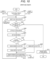
- FIG. 10 is a flowchart illustrating the operation of the flight vehicle operation management system 100 according to the second embodiment of the present invention
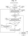
- FIG. 11 is a flowchart illustrating the operation of the flight vehicle control system 200.
- FIGS. 10 and 11 the description will be given assuming a takeoff time in the takeoff and landing operation.
- step S501 preparation for takeoff of the flight vehicle F4 at the airport apron Ab is completed in step S501.
- the takeoff and landing determination unit 104 allows takeoff using a flight plan of the flight vehicle F4 and the flight information of other flight vehicles received by the control information exchange unit 103, the aerial information of the airport 5 of the port information acquisition unit 105, the surrounding weather information, the airport information such as the presence or absence of emergency information, a takeoff application information Sg10 from the flight vehicle control system 200 of the flight vehicle F4 obtained by the communication unit 108, and the like, and notifies the flight vehicle F1 of a takeoff permission information Sg11 by using the communication unit 108. Thereafter, the process proceeds to step S502.
- step S601 the preparation for takeoff of the flight vehicle F4 at the airport apron Ab is completed, the takeoff application information Sg10 is transmitted to the flight vehicle operation management system 100, and by receiving the takeoff permission information Sg11 from the flight vehicle operation management system 100 as described above, the flight vehicle F4 shifts to a takeoff state.
- step S602 the state monitoring unit 202 installed in the flight vehicle F4 collects, for example, internal information such as the position, attitude, battery state of the flight vehicle F4, and control state of each device, and external information such as flight vehicles other than the flight vehicle F4 and obstacles acquired by the peripheral monitoring unit 203, and transmits the collected information to the flight vehicle operation management system 100 on the airport 5 side via the communication unit 201 as a flight vehicle information signal Sg12 of the flight vehicle F4.
- step S502 the flight vehicle detection unit 102 detects the position information of the flight vehicle F4 on the basis of the aerial information obtained by the aerial monitoring unit 101 installed in the airport 5 and flight vehicle position information included in the flight vehicle information signal Sg12 of the flight vehicle F4 transmitted from the flight vehicle control system 200 obtained by the communication unit 108.
- step S503 the takeoff and landing determination unit 104 determines whether the flight vehicle F4 arrives at a leaving airspace on the basis of the position information of the flight vehicle F4 and the state information of the flight vehicle F4.
- the leaving airspace is set at an upper end of the layered regions set above the airport 5. The process proceeds to step S504 in the case of before arriving at the leaving airspace, and proceeds to step S511 in the case of after arriving at the leaving airspace.
- the leaving airspace Before arriving at the leaving airspace, in step S504, the leaving airspace is designated by the flight vehicle operation management system 100 of the airport 5.
- the leaving airspace may be changed due to congestion in the airport, occurrence of the emergency, or the like.
- step S505 the occupied region setting unit 106 sets the occupied region O around the flight vehicle F4.
- R1 as the lowermost layer and R2 as an upper layer of R1 of the layered regions are set as occupied regions Ob1 and Ob2.
- the occupied region the three-dimensional body obtained by vertically extending the plane having the edge horizontally outward from the edge of the flight vehicle is set as the occupied region O.
- step S506 the takeoff and landing path design unit 107 determines where in the layered region R the flight vehicle F4 is flying on the basis of the position information of the flight vehicle F4. For example, determination is made by comparing a height of the flight vehicle F4 with the height of each region of the layered regions R set above the airport 5. If the flight vehicle is flying in the standby region R1 or R3, the process proceeds to step S507, and if the flight vehicle is flying in the transition region R2 or R4, the process proceeds to step S509.
- step S507 the takeoff and landing path design unit 107 designs a horizontal flight path in the standby region of the flight vehicle F4.
- the above-described method can be used as a method of designing the horizontal flight path.
- the process proceeds to step S508, and the takeoff and landing path design unit 107 designs a flight path in the vertical direction of the flight vehicle F4.
- the path can be designed so as to have a constant rising speed that does not damage the cargo.
- step S506 When it is determined in step S506 that the flight vehicle is flying in the transition regions R2 or R4, in step S509, the takeoff and landing path design unit 107 does not allow the path design in the horizontal direction since the flight vehicle F4 flies in the transition region.
- the flight path in the vertical direction can be designed so as to have, for example, the constant rising speed that does not damage the cargo.
- step S510 the communication unit 108 transmits information Sg14 on the occupied region O and the flight path to the flight vehicle control system 200 of the flight vehicle F4. Thereafter, the process proceeds to step S502.
- step S511 when it is determined in step S503 that it is after arriving at the leaving airspace, the communication unit 108 transmits the fact that the flight vehicle F4 has arrived at the leaving airspace to the flight vehicle control system 200 of the flight vehicle F4. Thereafter, the processing at the time of landing is ended.
- step S603 the flight control unit 204 determines whether the flight vehicle F4 arrives at the leaving airspace on the basis of the position information of the flight vehicle F4. Thereafter, the process proceeds to step S604 in the case of before arriving at the leaving airspace, and proceeds to step S608 in the case of after arriving at the leaving airspace.
- step S604 the state monitoring unit 202 acquires the information Sg14 on the occupied region O and the path plan assigned to the flight vehicle F4 from the flight vehicle operation management system 100 installed on the airport 5 side.
- step S605 the flight control unit 204 detects the obstacle around the flight vehicle F4 on the basis of the information of the state monitoring unit 202, and checks the presence or absence of the obstacle on the path assigned from the flight vehicle operation management system 100. If there is no obstacle, the process proceeds to step S607, and if there is the obstacle, the process proceeds to step S606.
- step S606 the flight control unit 204 detects the position of the obstacle on the basis of the information of the state monitoring unit 202, and corrects the movement path (Sg14) transmitted from the flight vehicle operation management system 100 so as to avoid the obstacle. At this time, when an avoidance path is designed in the occupied region O, contact with another flight vehicle can be avoided. Thereafter, the process proceeds to step S607.
- step S607 the flight vehicle flies to trace a path on the basis of the path information Sg14 by the flight control unit 204. Thereafter, the process proceeds to step S602, and is repeated until it is determined in S603 that the flight vehicle has arrived at the leaving airspace.
- step S608 arrival of the flight vehicle F4 at the leaving airspace is transmitted to the flight vehicle operation management system 100 via the communication unit 201.
- the utilization efficiency above the airport 5 is improved, and even when the airport is located in the narrow land, it is possible to stand by in the sky. Furthermore, by taking a large space below an aircraft, it is possible to avoid being affected by the airflow of another flight vehicle mainly in the takeoff and landing of the vertical takeoff and landing aircraft, and thus it is possible to realize safe flight of the flight vehicle above the airport 5.
- the same methods as those of the first embodiment can be used for a path design method, an occupied space design method, and the like, descriptions thereof will be omitted here.
- FIG. 12 is a schematic diagram of a cross-sectional view in a certain vertical plane of the airport 5 as viewed from right beside. Components common to those of the first embodiment and the second embodiment are denoted by the same reference numerals, and detailed descriptions thereof will be omitted.
- the layered region R is set above the airport 5 illustrated in FIG. 12 .
- An upper end of the layered region R can be set based on a height at which the flight vehicle can fly or the like. Configurations of other flight vehicles and the airport 5 are the same as those in the first and second embodiments.
- the flight vehicle F is allowed to move in both the horizontal direction and the vertical direction in the layered region.
- the occupied regions Oa, Ob, and Oc of the flight vehicle are set as three-dimensional bodies obtained by vertically extending the plane having the edge horizontally outward from the edge of the flight vehicle F from the upper end to the lower end of the layered region R.
- the flight vehicles F respectively move horizontally and vertically in the occupied regions Oa, Ob, and Oc.
- FIG. 13 is a schematic diagram of the occupied region O in contact with a plane of the upper end of the layered region R indicated by an arrow B in FIG. 12 .
- the flight vehicles F1, F2, and F3 can horizontally move together with the occupied regions Oa, Ob, and Oc.
- FIG. 13 illustrates movement loci 114, 115, and 116 when the flight vehicles F1, F2, and F3 and the occupied regions Oa, Ob, and Oc move.
- the movement loci of the occupied regions O at the time of movement can be designed not to come into contact with another occupied region O and another movement locus for each control cycle.
Landscapes
- Engineering & Computer Science (AREA)
- Aviation & Aerospace Engineering (AREA)
- Physics & Mathematics (AREA)
- General Physics & Mathematics (AREA)
- Traffic Control Systems (AREA)
Abstract
Description
- The present invention relates to a flight vehicle operation management system and a flight vehicle operation management method for a flight vehicle such as an aircraft.
- In recent years, there is an increasing need to use a small aircraft (an eVTOL: electric vertical takeoff and landing aircraft) capable of vertical takeoff and landing by rotating a plurality of rotor blades with an electric motor. The electric vertical takeoff and landing aircraft (eVTOL) is expected to solve various traffic problems such as reduction of traffic congestion and environmental load in urban areas, and securing of transportation means to underpopulated areas.
- In order to implement the small aircraft as described above as a social infrastructure, it is necessary to spread the small aircraft by realizing highly efficient operation of a large number of flight vehicles. In particular, at the time of takeoff and landing, the flight vehicle is unstable due to an influence of an airflow generated by another flight vehicle and the like, and thus it is important to ensure efficiency and safety.
- As a technique related to ensuring safe operation of the aircraft, for example, there is a technique described in PTL 1. PTL 1 discloses a technique of setting a partition in which a part of a landing area is virtually divided as a landing area for the purpose of efficiently using the landing area for a flight vehicle such as a drone, and performing landing processing in the landing area.
- PTL 1:
WO 2020/194495 A - PTL 1 proposes a method for efficiently using a takeoff and landing area assuming a state in which a plurality of flight vehicles fly into a takeoff and landing area assuming an airport. However, considering a future operation state, a high frequency of operation, installation of the airport in a city, and the like can also be considered, and thus there is a possibility that a sufficient region cannot be secured. Therefore, there are few flight vehicles that can stand by above the airport when flight frequency increases, and not only utilization efficiency of the airport decreases, but also flexible flight management such as changing a landing order according to a degree of urgency cannot be performed.
- Therefore, an object of the present invention is to provide a flight vehicle operation management system and a flight vehicle operation management method for an airport, the system and the method capable of increasing the utilization efficiency of the airport at the airport where a large number of flight vehicles having a vertical takeoff and landing function to take off and land.
- In order to achieve the above object, the present invention provides "a flight vehicle operation management system that manages flight-path planning and takeoff and landing of a flight vehicle at an airport including a plurality of airport aprons, in which the flight vehicle operation management system sets a layered region including at least one or more layers above the airport, and an occupied region around the flight vehicle, and the occupied region is set in the layered region in which the flight vehicle flies and in at least one of layered regions vertically adjacent to the layered region".
- Further, the present invention provides "a flight vehicle operation management method in an airport including an airport apron, the flight vehicle operation management method including: setting a layered region including at least one or more layers above the airport to allow a flight vehicle to move in the layered region and take off and land; and setting an occupied region around the flight vehicle in the layered region, in which the occupied region is set in the layered region in which the flight vehicle flies and in at least one of layered regions vertically adjacent to the layered region".
- According to the present invention, it is possible to provide a flight vehicle operation management system and a flight vehicle control system capable of efficiently and safely taking off and landing a plurality of flight vehicles at an airport.
-
- [
FIG. 1] FIG. 1 is a conceptual diagram illustrating a relationship between a flight vehicle, an airport, a layered region of the airport, and an occupied region of the flight vehicle according to a first embodiment of the present invention. - [
FIG. 2] FIG. 2 is a block diagram illustrating a configuration example of a flight vehicle operation management system installed in the airport and a flight vehicle control system installed in the flight vehicle according to the first embodiment of the present invention. - [
FIG. 3] FIG. 3 is a schematic diagram of a cross-sectional view in a certain vertical plane of the airport as viewed from right beside. - [
FIG. 4] FIG. 4 is a schematic diagram illustrating a relationship between height setting of the layered region and an airflow generated by the flight vehicle. - [
FIG. 5] FIG. 5 is a schematic diagram of the occupied region in contact with a plane of an upper end of a standby region indicated by an arrow I inFIG. 3 . - [
FIG. 6] FIG. 6 is a flowchart illustrating an operation flow of the flight vehicle operation management system at the time of landing according to the first embodiment of the present invention. - [
FIG. 7] FIG. 7 is a flowchart illustrating an operation flow of the flight vehicle control system at the time of landing according to the first embodiment of the present invention. - [
FIG. 8] FIG. 8 is a schematic diagram illustrating that only a region in which a flight vehicle F1 flies and a region below the region is occupied. - [
FIG. 9] FIG. 9 is a schematic diagram illustrating the occupied region having a trapezoidal cross-sectional shape. - [
FIG. 10] FIG. 10 is a flowchart illustrating an operation flow of the flight vehicle operation management system at the time of takeoff according to a second embodiment of the present invention. - [
FIG. 11] FIG. 11 is a flowchart illustrating an operation flow of the flight vehicle control system at the time of takeoff according to the second embodiment of the present invention. - [
FIG. 12] FIG. 12 is a schematic diagram illustrating another example of a cross-sectional view in a certain vertical plane of the airport. - [
FIG. 13] FIG. 13 is a schematic diagram illustrating another example of a cross-sectional view in a certain vertical plane of the airport. - Hereinafter, embodiments of the present invention will be described with reference to the drawings.
- Note that in the drawings, the same components are denoted by the same reference numerals, and overlapping similar descriptions may be omitted. In addition, various components of the present invention do not necessarily have to be independent from each other, and it is allowable that one component includes a plurality of members, a plurality of components includes one member, a certain component is a part of another component, a part of a certain component overlaps with a part of another component, and the like.
-
FIG. 1 is a conceptual diagram illustrating a relationship between a flight vehicle, an airport, a layered region of the airport, and an occupied region of the flight vehicle according to a first embodiment of the present invention. -
FIG. 1 illustrates a state in which flight vehicles F (F1 to F4) is capable of vertical takeoff and landing with a plurality of rotor blades and are flying into anairport 5 at the same time. The flight vehicles F are used for applications such as boarding of a user, carrying of luggage, and photographing of aerial photographs. In addition, the flight vehicle F includes a flightvehicle control device 200 that controls flight of the flight vehicle F described later with reference toFIG. 2 inside the flight vehicle F. - The
airport 5 includes a plurality of airport aprons A (Aa, Ab) where the flight vehicles F take off and land, acontrol facility 8 that manages takeoff and landing in the airport, and anaerial monitoring unit 9 including a sensor that monitors a position and a state of the flight vehicle F above theairport 5. As will be described in detail later with reference toFIG. 2 , a flight vehicleoperation management system 100 is installed in thecontrol facility 8, and manages takeoff and landing on the basis of a state of the airport apron A of theairport 5, surrounding weather conditions, and the state of the flight vehicle F. - The flight vehicle
operation management system 100 of the present invention sets layered regions R (Ra to Rd) which are layered virtual regions above theairport 5. The layered region R is obtained by dividing a sky region of theairport 5 into a plurality of layers, and is set as the sky region of theairport 5. - Further, in the layered regions R, for example, four layers of R1, R2, R3, and R4 are sequentially formed in ascending order of height in a height direction. In the layered regions R configured as described above, the flight vehicle F (for example, F3) sequentially passes through the layers R1, R2, and R3 in the layered region from the airport apron Aa, and starts navigation from R4 toward a destination. Here, among the layers, R1 as a lowermost layer is to be referred to as an aircraft parking layer for parking the flight vehicle F, R4 as an uppermost layer is to be referred to as a takeoff and landing layer since it is an entrance for entering and exiting the airport apron, and R2 and R4 are layers that allow the flight vehicle F to move in a horizontal direction, and play a role as a standby layer that allows other flight vehicles F to take off and land preferentially by allowing the flight vehicle F to move in the horizontal direction.
- As described above, in the system of
FIG. 1 , the layered regions R are set above theairport 5 according to an altitude by the flight vehicleoperation management system 100, and in which region the flight vehicle is flying is grasped using information of the flight vehicleoperation management system 100 and the flightvehicle control system 200. - Further, occupied regions O (Oa to Od) of the flight vehicles are set around the flight vehicles F (F1 to F4) that have flown into the
airport 5. The occupied region O has a three-dimensional shape obtained by vertically extending a plane wider in the horizontal direction than an outer edge of, for example, F3 as a flight vehicle, and occupies in a vertical direction at least a region in which the flight vehicle F3 is currently flying. In the case of the flight vehicle F3 inFIG. 1 , an R2 layer among the layered regions R is an occupied region Oc2 (the number (2) indicates a suffix (in this case, 2) of the layered region R) in which the flight vehicle F3 occupies in the vertical direction a region in which the flight vehicle F3 is currently flying. - Further in the present invention, the occupied region Oc is set including the layered region R2 in which the flight vehicle F3 is currently flying and occupied regions Oc1 and Oc3 set in the layered regions R1 and R3 vertically adjacent to the layered region R2. Note that although the occupied region O is described as a tubular shape here, the occupied region O may be set as a rectangular parallelepiped or the like.
- Thus, the flight vehicles F (F1 to F4) flying into the
airport 5 descend along flight paths set inside the occupied regions O, land on the airport aprons Aa and Ab, and take off. - Next, functional configurations of the flight vehicle
operation management system 100 installed in theairport 5 and flightvehicle control systems 200 installed in the flight vehicles F1 to F4 will be described.FIG. 2 is a block diagram illustrating a configuration example of the flight vehicleoperation management system 100 and the flightvehicle control system 200 according to the first embodiment of the present invention. - In
FIG. 2 , the flight vehicleoperation management system 100 includes anaerial monitoring unit 101 described above, a flightvehicle detection unit 102 that detects the position, state, and the like of the flight vehicle, a controlinformation exchange unit 103 that acquires information of a flight vehicle flying in another airport or outside the airport and transmits information of the flight vehicle present in the airport, a takeoff andlanding determination unit 104 that determines takeoff and landing of the flight vehicle in the airport, a portinformation acquisition unit 105 that acquires airport peripheral information such as space availability of the airport apron, climate (wind, wind and rain, and the like), the number of passengers, and the like, an occupiedregion setting unit 106 that sets the occupied region O of the flight vehicle, a takeoff and landingpath design unit 107 that generates the flight path in the occupied region of the flight vehicle, and acommunication unit 108 that transmits a takeoff and landing path and a position of the occupied region O to the flightvehicle control system 200, and receives surrounding conditions based on a sensor of the flight vehicle, and a current position of the flight vehicle, and the like. - The flight
vehicle control system 200 installed in the flight vehicle includes acommunication unit 201 on the flightvehicle control system 200 side that exchanges signals with thecommunication unit 108 of the flight vehicleoperation management system 100, astate monitoring unit 202 that monitors a posture, a position, a battery charge amount, a state of a device and the like of the flight vehicle, aperipheral monitoring unit 203 including a sensor that detects another flight vehicle, an obstacle, and the like around the flight vehicle, and aflight control unit 204 that controls a flight of the flight vehicle based on the state of the flight vehicle obtained by thestate monitoring unit 202 based on takeoff and landing path information and information on the occupied region O received by thecommunication unit 201, and information around the flight vehicle obtained by the peripheral monitoring unit. - Further,
FIG. 3 is a schematic diagram of a cross-sectional view in a certain vertical plane of theairport 5 as viewed from right beside. The layered regions R and the occupied regions O set above theairport 5 will be described with reference toFIG. 3 . In an example ofFIG. 3 , the layered regions R are set above theairport 5. An upper end layer R4 of the layered regions R is preferably set based on a height at which the flight vehicle F can fly or the like.FIG. 3 illustrates an example in which the occupied region is not set because a flight vehicle F5 is out of a management region by the layered region R. - Note that in
FIG. 3 , regions in the height direction of the airport aprons A (Aa, Ab, and Ac) are the layered regions R, and portions with background colors in the layered regions represent the occupied regions O (Oc, Oa, and Ob) respectively set for the flight vehicles F (F1, F3, and F4). Further, arrows illustrated on the flight vehicles F (F1, F3, and F4) indicate movable directions of the flight vehicles. -
FIG. 4 is a schematic diagram illustrating a relationship between height setting of the layered region and an airflow generated by the flight vehicle. - Here, a design example of each layer of the layered regions will be described with reference to
FIG. 4. FIG. 4 illustrates the flight vehicles F1 and F2 flying in upper and lower layered regions R1 and R3 with, for example, R2 (indicated by gray hatching) as one layer region of the layered regions interposed therebetween. This figure illustrates a state in which the flight vehicle F1 is flying in contact with an upper end of the one layer region R2, and the flight vehicle F2 is flying in contact with a lower end of the one layer region R2. - In
FIG. 4 , a part of flow of the airflow generated by a fan of the flight vehicle F1 is indicated by astreamline 110. - As illustrated in the figure, in the case of the flight vehicle F1 assuming the vertical takeoff and landing aircraft, a large airflow is generated in the vertical direction of the flight vehicle F1. In particular, since a downward airflow is large, a height of the one layer region R2 of the layered regions is preferably set higher than an influence range of the downward airflow as illustrated in
FIG. 4 . By setting the height in this manner, when a plurality of flight vehicles fly, the airflow generated by a flight vehicle above does not affect a flight vehicle below by sandwiching one layered region R between the flight vehicles. - Although
FIG. 4 illustrates a method of determining the height on the basis of the influence range of the airflow generated by the fan of the flight vehicle, and in addition to this, the height can be determined on the basis of an expected movement amount until recovery after a partial failure of the flight vehicle, disturbance such as an expected weather change, an movement amount of the flight vehicle required to avoid an intruder such as a bird, and the like. - In addition, it is preferable that the layered regions R1, R2, R3, and R4 have different roles depending on, for example, the height and are configured by transition regions R1 and R3 and standby regions R2 and R4. Here, in the transition regions R1 and R3, the position of the occupied region O cannot be moved when the flight vehicle F flies in these regions, and when the flight vehicle F flies in the standby regions R2 and R4, the position of the occupied region O can be changed in the horizontal direction together with the flight vehicle F while avoiding contact with other occupied regions O.
- Further, the occupied region O of the flight vehicle F is set as a three-dimensional occupied region O around the flight vehicle F.
- The occupied region O has a three-dimensional shape obtained by vertically extending a plane set wider than the outer edge of the flight vehicle F in the horizontal direction. For example, as illustrated in
FIG. 3 , the occupied region O is preferably extended over regions (transition regions R1 and R3) vertically adjacent to the region (standby region R2) in which the flight vehicle F flies. - In this way, by alternately arranging the transition regions R1 and R3 and the standby regions R2 and R4 and setting the occupied region O, only a movement path in the vertical direction is basically designed in the transition regions R1 and R3, and a movement path in the horizontal direction is designed in the standby regions R2 and R4. For example, movement in the horizontal direction is designed as illustrated in
FIG. 5 . -
FIG. 5 is a schematic diagram of the occupied region O in contact with a plane of the upper end of the standby region R2 indicated by an arrow I inFIG. 3 . The flight vehicles F1 and F3 flying in the standby region can horizontally move 114 and 116 together with the occupied regions Oa and Oc. The occupied region Od of the flight vehicle F2 is not allowed to horizontally move because the flight vehicle is flying in the transition region.FIG. 5 illustratesmovement loci - As described in this figure, the locus of the occupied region O at the time of movement can be designed not to come into contact with another occupied region O and another movement locus for each control cycle. However, the occupied region Oa of the flight vehicle F3 is at a vertical position that is not in contact with the occupied region Od, and thus the occupied region Oa and the
movement locus 116 may be designed to be allowed to contact and overlap with each other although the path is not in contact with another path in this drawing. - In addition, the layered regions are preferably set such that the transition regions R1 and R3 are higher than the standby regions R2 and R4. Since the standby regions R1 and R3 require path design in the horizontal direction and the vertical direction, an increase in processing load or the like is assumed, and the transition regions R1 and R3 are preferably set high in order to shorten takeoff and landing time.
- Next, operations of the flight vehicle
operation management system 100, the flightvehicle control system 200, and the flight vehicle F1 will be described.FIG. 6 is a flowchart illustrating the operation of the flight vehicleoperation management system 100 according to the first embodiment of the present invention, andFIG. 7 is a flowchart illustrating the operation of the flightvehicle control system 200. Hereinafter, inFIGS. 6 and7 , a description will be given assuming a landing time in a takeoff and landing operation. InFIG. 7 , the flight vehicle F1 of the plurality of flight vehicles F1 to F4 illustrated inFIG. 3 will be described as an example. - Flows of
FIGS. 6 and7 are respectively operated in the flight vehicleoperation management system 100 and the flightvehicle control system 200, and there is a relationship in which signals are exchanged at an appropriate timing to affect each other. Therefore, in the following description, mutual operations will be described in chronological order. - A first stage of
FIGS. 6 and7 is a state in which the flight vehicle F1 is approaching above the airport. - At this time, in processing step S301 of the flight vehicle
operation management system 100 installed in theairport 5 inFIG. 6 , when the flight vehicle arrives above the airport, permission to land is determined, and a landing permission signal Sg1 is notified to the flight vehicle F1. - More specifically, in step S301, the flight vehicle F1 arrives above the
airport 5, and the flightvehicle detection unit 104 detects the flight vehicle F1 on the basis of aerial information of theaerial monitoring unit 101 installed in theairport 5 and position information of the flight vehicle F1 of the flightvehicle control system 200 from thecommunication unit 108. In addition, the takeoff andlanding determination unit 104 determines landing on theairport 5 by using situation above theairport 5 by theaerial monitoring unit 101, a flight plan of the flight vehicle F1 and flight information of other flight vehicles received by the controlinformation exchange unit 103, airport apron availability information of theairport 5 of the portinformation acquisition unit 105, surrounding weather information, airport information such as the presence or absence of emergency information, a landing application signal Sg0 from the flightvehicle control system 200 of the flight vehicle F1 obtained by thecommunication unit 108, and the like, and notifies the flight vehicle F1 of the landing permission signal Sg1 by using thecommunication unit 108. Thereafter, the process proceeds to step S302. - On the other hand, at this time, in processing step S401 of the flight
vehicle control system 200 on the flight vehicle side, the flight vehicle F1 arrives above theairport 5 and transitions to a landing state. - More specifically, in step S401 in
FIG. 7 , when the flight vehicle F1 arrives above theairport 5, it is determined that the flight vehicle F1 has entered the region of theairport 5, and the landing application signal Sg0 is transmitted. Further, as described above, the flight vehicle F1 transitions to the landing state by receiving the landing permission signal Sg1 from the flight vehicleoperation management system 100. - Thereafter, the process proceeds to step S402, and the
state monitoring unit 202 installed in the flight vehicle F1 collects, for example, internal information such as the position, attitude, battery state of the flight vehicle F1, and control state of each device, and external information such as flight vehicles other than the flight vehicle F1 and obstacles acquired by theperipheral monitoring unit 203, and transmits the collected information to the flight vehicleoperation management system 100 on theairport 5 side via thecommunication unit 201 as a flight vehicle information signal Sg2. Note that processing in step S402 is processing continuously executed in a flight state. - In step S403, it is determined whether it is the flight state, and when it is the flight state, processing in step S404 is continuously executed.
- In processing step S302 of the flight vehicle
operation management system 100 installed in theairport 5 inFIG. 6 , the flight vehicle information signal Sg2 transmitted in step S402 inFIG. 7 is received, and the position of the flight vehicle is detected. Specifically, the flightvehicle detection unit 102 detects the position information of the flight vehicle F1 on the basis of the aerial information obtained by theaerial monitoring unit 101 installed in theairport 5 and the position information of the flight vehicle F1 included in the flight vehicle information signal Sg2 transmitted from the flightvehicle control system 200 obtained by thecommunication unit 108. Thereafter, the process proceeds to step S303. - In step S303, the takeoff and
landing determination unit 104 determines whether the flight vehicle F1 is in the flight state or the landing state on the basis of the position information of the flight vehicle F1 and the state information of the flight vehicle F1. The process proceeds to step S304 in the case of the flight state, and the process proceeds to step S311 in the case of the landing state. - In step S304, an airport apron designated by the flight vehicle
operation management system 100 of theairport 5 is determined as a landing position. This parking position may be changed due to availability of the airport apron, congestion in the airport, occurrence of an emergency, or the like. Thereafter, the process proceeds to step S305. - In step S305, the occupied
region setting unit 106 sets the occupied region O around the flight vehicle F1. In the present embodiment, as described above, in the occupied region O, a three-dimensional body obtained by vertically extending a plane having an edge horizontally outward from the edge of the flight vehicle is set as the occupied region O. Thereafter, the process proceeds to step S306. - In step S306, the takeoff and landing
path design unit 107 determines where in the layered region R the flight vehicle F1 is flying on the basis of the position information of the flight vehicle F1. For example, determination is made by comparing a height of the flight vehicle F1 with a height of each region of the layered regions R set above theairport 5. If the flight vehicle is flying in the standby region, the process proceeds to step S307, and if the flight vehicle is flying in the transition region, the process proceeds to step S309. - In step S307, the takeoff and landing
path design unit 107 designs a horizontal flight path in the standby region of the flight vehicle F1. The above-described method can be used as a method of designing the horizontal flight path. Thereafter, the process proceeds to step S308. - In step S308, the takeoff and landing
path design unit 107 designs a flight path in the vertical direction of the flight vehicle F1. For example, the path can be designed so as to have a constant descent speed that does not damage cargo. Thereafter, the process proceeds to step S309. - In step S309, since the flight vehicle F1 flies in the transition region, the takeoff and landing
path design unit 107 does not allow the path design in the horizontal direction. The flight path in the vertical direction can be designed so as to have, for example, the constant descent speed that does not damage the cargo. Thereafter, the process proceeds to step S310. - In step S310, the
communication unit 108 transmits information Sg3 on the occupied region O and the flight path to the flightvehicle control system 200 of the flight vehicle F1. Thereafter, the process returns to step S302, and the above processing is repeated. - Note that in step S311, when the flight vehicle F1 lands, the
communication unit 108 transmits landing completion information Sg4 to the flightvehicle control system 200 of the flight vehicle F1, and ends processing at the time of landing. - Next, an example of a processing flow of the flight
vehicle control system 100 installed in the flight vehicle F1 after receiving the information Sg3 on the flight path in step S404 ofFIG. 7 will be described. Note that in this state, in step S403, it has been determined whether the flight vehicle F1 is in the flight state or the landing state on the basis of the position information of the flight vehicle F1 and the state information of the flight vehicle F1, and it has been confirmed that the flight vehicle F1 is in the flight state. - In step S404 of
FIG. 7 , the flight unit F1 in flight acquires the information Sg3 on the occupied region O and a path plan assigned to the flight vehicle F1 from the flight vehicleoperation management system 100 installed on theairport 5 side by thestate monitoring unit 202. - Next, in step S405, the
flight control unit 204 detects an obstacle around the flight vehicle F1 on the basis of information of thestate monitoring unit 202, and checks the presence or absence of the obstacle on the path assigned from the flight vehicleoperation management system 100. If there is no obstacle, the process proceeds to step S407, and if there is the obstacle, the process proceeds to step S406. - When there is the obstacle, in step S406, the
flight control unit 204 detects a position of the obstacle on the basis of the information of thestate monitoring unit 202, and corrects the movement path transmitted from the flight vehicleoperation management system 100 so as to avoid the obstacle. At this time, when an avoidance path is designed in the occupied region O, contact with another flight vehicle can be avoided. - If it is determined in step S405 that there is no obstacle or if the path is corrected in step S406, the flight is performed according to these pieces of path information in step S407. Thereafter, the process proceeds to step S402, and is repeated until landing is determined in S403.
- Note that in step S408, the landing completion information of the flight vehicle F1 is transmitted to the flight vehicle operation management system via the
communication unit 201. - In the first embodiment, a landing operation of the flight vehicle F1 is performed as described above. By performing such a landing operation, the utilization efficiency above the
airport 5 is improved, and even when the airport is located in a narrow land, it is possible to stand by in the sky. Furthermore, by taking a large space below an aircraft, it is possible to avoid being affected by the airflow of another flight vehicle mainly in the takeoff and landing of the vertical takeoff and landing aircraft, and thus it is possible to realize safe flight of the flight vehicle above theairport 5. - In addition, by setting the layered region R, alternately setting each of the regions to the standby region and the transition region, and adding movement restriction of the flight vehicle for each region, it is possible to design paths in a planar space as illustrated in
FIG. 5 , and it is possible to reduce a calculation load by the flight vehicleoperation management system 100 and realize smooth operation management. - Note that
FIGS. 1 and3 illustrate horizontal widths of the occupied regions O of the plurality of flight vehicles as being the same, but each of the widths may be changed according to a size and performance of the flight vehicle and the climate around theairport 5. - Further, the height of the layered region R may also be changed according to the climate around the
airport 5. - This makes it possible to fly safely even when position control of the flight vehicle F1 is not stable, such as when the wind is strong.
- In addition,
FIGS. 1 and3 illustrate an example in which the flight vehicle F1 occupies the region in which the flight vehicle F1 flies and regions above and below the region, however, as illustrated inFIG. 8 , even if the flight vehicle F1 occupies the region in which the flight vehicle F1 flies and only a region below the region, an effect substantially the same as the above-described content can be obtained. - In addition, as illustrated in
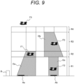
FIG. 9 , when an entry angle with respect to theairport 5 is required, safety below the flight vehicle can be secured by setting the occupied region O having a trapezoidal cross-sectional shape. - In a second embodiment of the present invention, an operation at the time of takeoff will be described with reference to
FIGS. 10 and11 .FIG. 10 is a flowchart illustrating the operation of the flight vehicleoperation management system 100 according to the second embodiment of the present invention, andFIG. 11 is a flowchart illustrating the operation of the flightvehicle control system 200. Hereinafter, inFIGS. 10 and11 , the description will be given assuming a takeoff time in the takeoff and landing operation. - First, according to an example of a processing flow of the flight vehicle
operation management system 100 installed in theairport 5, preparation for takeoff of the flight vehicle F4 at the airport apron Ab is completed in step S501. The takeoff andlanding determination unit 104 allows takeoff using a flight plan of the flight vehicle F4 and the flight information of other flight vehicles received by the controlinformation exchange unit 103, the aerial information of theairport 5 of the portinformation acquisition unit 105, the surrounding weather information, the airport information such as the presence or absence of emergency information, a takeoff application information Sg10 from the flightvehicle control system 200 of the flight vehicle F4 obtained by thecommunication unit 108, and the like, and notifies the flight vehicle F1 of a takeoff permission information Sg11 by using thecommunication unit 108. Thereafter, the process proceeds to step S502. - Further, at this timing, the processing flow of the flight
vehicle control system 100 installed in the flight vehicle F4 operates as follows. - On the flight vehicle F4 side, as illustrated in
FIG. 11 , in step S601, the preparation for takeoff of the flight vehicle F4 at the airport apron Ab is completed, the takeoff application information Sg10 is transmitted to the flight vehicleoperation management system 100, and by receiving the takeoff permission information Sg11 from the flight vehicleoperation management system 100 as described above, the flight vehicle F4 shifts to a takeoff state. - Thereafter, the process proceeds to step S602, and the
state monitoring unit 202 installed in the flight vehicle F4 collects, for example, internal information such as the position, attitude, battery state of the flight vehicle F4, and control state of each device, and external information such as flight vehicles other than the flight vehicle F4 and obstacles acquired by theperipheral monitoring unit 203, and transmits the collected information to the flight vehicleoperation management system 100 on theairport 5 side via thecommunication unit 201 as a flight vehicle information signal Sg12 of the flight vehicle F4. - Next, returning to processing on the airport side in
FIG. 10 again, in step S502, the flightvehicle detection unit 102 detects the position information of the flight vehicle F4 on the basis of the aerial information obtained by theaerial monitoring unit 101 installed in theairport 5 and flight vehicle position information included in the flight vehicle information signal Sg12 of the flight vehicle F4 transmitted from the flightvehicle control system 200 obtained by thecommunication unit 108. - Next, in step S503, the takeoff and
landing determination unit 104 determines whether the flight vehicle F4 arrives at a leaving airspace on the basis of the position information of the flight vehicle F4 and the state information of the flight vehicle F4. The leaving airspace is set at an upper end of the layered regions set above theairport 5. The process proceeds to step S504 in the case of before arriving at the leaving airspace, and proceeds to step S511 in the case of after arriving at the leaving airspace. - Before arriving at the leaving airspace, in step S504, the leaving airspace is designated by the flight vehicle
operation management system 100 of theairport 5. The leaving airspace may be changed due to congestion in the airport, occurrence of the emergency, or the like. - Next, in step S505, the occupied
region setting unit 106 sets the occupied region O around the flight vehicle F4. In this case, at an initial stage when the flight vehicle F4 is in a parking state, R1 as the lowermost layer and R2 as an upper layer of R1 of the layered regions are set as occupied regions Ob1 and Ob2. Note that as described above, in the occupied region, the three-dimensional body obtained by vertically extending the plane having the edge horizontally outward from the edge of the flight vehicle is set as the occupied region O. - Thereafter, in step S506, the takeoff and landing
path design unit 107 determines where in the layered region R the flight vehicle F4 is flying on the basis of the position information of the flight vehicle F4. For example, determination is made by comparing a height of the flight vehicle F4 with the height of each region of the layered regions R set above theairport 5. If the flight vehicle is flying in the standby region R1 or R3, the process proceeds to step S507, and if the flight vehicle is flying in the transition region R2 or R4, the process proceeds to step S509. - When the flight vehicle is flying in the standby regions R1 or R3, in step S507, the takeoff and landing
path design unit 107 designs a horizontal flight path in the standby region of the flight vehicle F4. The above-described method can be used as a method of designing the horizontal flight path. Thereafter, the process proceeds to step S508, and the takeoff and landingpath design unit 107 designs a flight path in the vertical direction of the flight vehicle F4. For example, the path can be designed so as to have a constant rising speed that does not damage the cargo. - When it is determined in step S506 that the flight vehicle is flying in the transition regions R2 or R4, in step S509, the takeoff and landing
path design unit 107 does not allow the path design in the horizontal direction since the flight vehicle F4 flies in the transition region. The flight path in the vertical direction can be designed so as to have, for example, the constant rising speed that does not damage the cargo. - Thereafter, the process proceeds to step S510, and the
communication unit 108 transmits information Sg14 on the occupied region O and the flight path to the flightvehicle control system 200 of the flight vehicle F4. Thereafter, the process proceeds to step S502. - Note that, in processing of step S511 when it is determined in step S503 that it is after arriving at the leaving airspace, the
communication unit 108 transmits the fact that the flight vehicle F4 has arrived at the leaving airspace to the flightvehicle control system 200 of the flight vehicle F4. Thereafter, the processing at the time of landing is ended. - Returning to
FIG. 11 , processing on the flight vehicle side after obtaining the takeoff permission information Sg11 will be described. First, in step S603, theflight control unit 204 determines whether the flight vehicle F4 arrives at the leaving airspace on the basis of the position information of the flight vehicle F4. Thereafter, the process proceeds to step S604 in the case of before arriving at the leaving airspace, and proceeds to step S608 in the case of after arriving at the leaving airspace. - In the case of before arriving at the leaving airspace, in step S604, the
state monitoring unit 202 acquires the information Sg14 on the occupied region O and the path plan assigned to the flight vehicle F4 from the flight vehicleoperation management system 100 installed on theairport 5 side. - Thereafter, in step S605, the
flight control unit 204 detects the obstacle around the flight vehicle F4 on the basis of the information of thestate monitoring unit 202, and checks the presence or absence of the obstacle on the path assigned from the flight vehicleoperation management system 100. If there is no obstacle, the process proceeds to step S607, and if there is the obstacle, the process proceeds to step S606. - When there is the obstacle, in step S606, the
flight control unit 204 detects the position of the obstacle on the basis of the information of thestate monitoring unit 202, and corrects the movement path (Sg14) transmitted from the flight vehicleoperation management system 100 so as to avoid the obstacle. At this time, when an avoidance path is designed in the occupied region O, contact with another flight vehicle can be avoided. Thereafter, the process proceeds to step S607. - When there is no obstacle, in step S607, the flight vehicle flies to trace a path on the basis of the path information Sg14 by the
flight control unit 204. Thereafter, the process proceeds to step S602, and is repeated until it is determined in S603 that the flight vehicle has arrived at the leaving airspace. - Note that after arriving at the leaving airspace, in step S608, arrival of the flight vehicle F4 at the leaving airspace is transmitted to the flight vehicle
operation management system 100 via thecommunication unit 201. - Note that the above procedure is an example, and in actual takeoff, it is preferable to take off from a state in which the path information Sg14 is given. In the second embodiment, a takeoff operation of the flight vehicle F4 is performed as described above.
- As described above, by performing the takeoff operation of the flight vehicle F4, the utilization efficiency above the
airport 5 is improved, and even when the airport is located in the narrow land, it is possible to stand by in the sky. Furthermore, by taking a large space below an aircraft, it is possible to avoid being affected by the airflow of another flight vehicle mainly in the takeoff and landing of the vertical takeoff and landing aircraft, and thus it is possible to realize safe flight of the flight vehicle above theairport 5. In addition, since the same methods as those of the first embodiment can be used for a path design method, an occupied space design method, and the like, descriptions thereof will be omitted here. - A third embodiment of the present invention will be described with reference to
FIGS. 12 and13 . Similarly toFIG. 3 of the first embodiment,FIG. 12 is a schematic diagram of a cross-sectional view in a certain vertical plane of theairport 5 as viewed from right beside. Components common to those of the first embodiment and the second embodiment are denoted by the same reference numerals, and detailed descriptions thereof will be omitted. - Unlike
FIG. 3 , only the layered region R is set above theairport 5 illustrated inFIG. 12 . An upper end of the layered region R can be set based on a height at which the flight vehicle can fly or the like. Configurations of other flight vehicles and theairport 5 are the same as those in the first and second embodiments. - In this configuration, the flight vehicle F is allowed to move in both the horizontal direction and the vertical direction in the layered region. In addition, the occupied regions Oa, Ob, and Oc of the flight vehicle are set as three-dimensional bodies obtained by vertically extending the plane having the edge horizontally outward from the edge of the flight vehicle F from the upper end to the lower end of the layered region R.
- The flight vehicles F respectively move horizontally and vertically in the occupied regions Oa, Ob, and Oc.
- With such occupied region setting, the paths of the flight vehicles F1, F2, and F3 can be designed in a plane as illustrated in
FIG. 13. FIG. 13 is a schematic diagram of the occupied region O in contact with a plane of the upper end of the layered region R indicated by an arrow B inFIG. 12 . The flight vehicles F1, F2, and F3 can horizontally move together with the occupied regions Oa, Ob, and Oc.FIG. 13 illustratesmovement loci - Since an operation flow at the time of flight is the same as that at the time of landing except for steps S306 and S309 in
FIG. 6 of the first embodiment and at the time of takeoff except for steps S503 and S509 inFIG. 10 of the second embodiment, a description thereof will be omitted here. - By performing design and operation in the sky region of the
airport 5 as described above, collision between the plurality of flight vehicles does not occur, and there is no influence of the airflow generated by the flight vehicle, and thus it is possible to realize safe flight of the flight vehicle in the airport. In addition, since a movement path for avoiding the collision between the plurality of flight vehicles can be designed in a plane, it is possible to reduce the calculation load by the flight vehicleoperation management system 100 and realize smooth operation management. - Note that the present invention is not limited to the above-described embodiments, and includes various modifications.
- The above-described embodiments have been described in detail in order to describe the present invention in an easy-to-understand manner, and are not necessarily limited to those having all described configurations.
-
- F1, F2, F3, F4, F5 flight vehicle with vertical takeoff and landing function
- 5 airport
- Aa, Ab airport apron
- 8 control facility
- 9 aerial monitoring unit
- R1, R2, R3, R4 layered region
- R2, R4 standby region
- R1, R3 transition region
- Oa, Ob, Oc, Od occupied region
- 100 flight vehicle operation management system
- 101 aerial monitoring unit
- 102 flight vehicle detection unit
- 103 control information exchange unit
- 104 takeoff and landing determination unit
- 105 port information acquisition unit
- 106 occupied region setting unit
- 107 takeoff and landing path design unit
- 108 (airport-side) communication unit
- 200 flight vehicle control system
- 201 (flight vehicle-side) communication unit
- 202 state monitoring unit
- 203 peripheral monitoring unit
- 204 flight vehicle control unit
Claims (17)
- A flight vehicle operation management system that manages flight-path planning and takeoff and landing of a flight vehicle at an airport including a plurality of airport aprons, whereinthe flight vehicle operation management system sets a layered region including at least one or more layers above the airport, and an occupied region around the flight vehicle, andthe occupied region is set in the layered region in which the flight vehicle flies and in at least one of layered regions vertically adjacent to the layered region.
- The flight vehicle operation management system according to claim 1, wherein
a three-dimensional body obtained by vertically extending a plane having an edge horizontally outside an edge of the flight vehicle is set as the occupied region of the flight vehicle. - The flight vehicle operation management system according to claim 2, wherein
a horizontal direction width of the occupied region is smaller than a vertical direction height. - The flight vehicle operation management system according to claim 2, wherein
a height of the occupied region is set to a height of the layered region in which the flight vehicle flies and the layered regions vertically adjacent to the layered region. - The flight vehicle operation management system according to claim 2, wherein
a height of the layered region is set higher than a height at which a flight vehicle flying at a lower end of the layered region does not affect a flight vehicle flying at an upper end of the layered region two layers below the layered region. - The flight vehicle operation management system according to claim 5, wherein
the height of the layered region is designed based on an influence range of an airflow generated by the flight vehicle. - The flight vehicle operation management system according to claim 5, wherein
the height of the layered region is designed based on a fall amount calculated based on a time for recovery from a failure assumed in the flight vehicle. - The flight vehicle operation management system according to claim 5, wherein
heights of the occupied region and the layered region have a margin for movement of the flight vehicle expected due to wind, avoidance of an intruder, and the like. - The flight vehicle operation management system according to claim 2, wherein
when the flight vehicle moves to another one of the layered regions, occupation of a region other than the layered region in which the flight vehicle flies and the layered regions vertically adjacent to the layered region is canceled. - The flight vehicle operation management system according to claim 1, wherein
the layered region includes a standby region that allows the flight vehicle to move in a horizontal direction of the occupied region in which the flight vehicle exists, and a transition region that does not allow the flight vehicle to move in the horizontal direction of the occupied region in which the flight vehicle exists. - The flight vehicle operation management system according to claim 10, wherein
a height of the layered region is higher in the transition region than in the standby region. - The flight vehicle operation management system according to claim 10, wherein
when the layered region includes one layer, the layered region is treated as the standby region. - The flight vehicle operation management system according to claim 10, wherein
when there are a plurality of occupied regions in the standby region, a path for moving the flight vehicle and the occupied region is designed such that the occupied regions of flight vehicles flying in the standby region do not come into contact with each other. - The flight vehicle operation management system according to claim 10, wherein
when there is an intruder from an outside, the flight vehicle designs a path to avoid the intruder within the occupied region. - The flight vehicle operation management system according to claim 10, wherein
the airport includes a sensor that detects a position and a state of the flight vehicle. - A flight vehicle operation management method in an airport including an airport apron, the flight vehicle operation management method comprising:setting a layered region including at least one or more layers above the airport to allow a flight vehicle to move in the layered region and take off and land; andsetting an occupied region around the flight vehicle in the layered region, whereinthe occupied region is set in the layered region in which the flight vehicle flies and in at least one of layered regions vertically adjacent to the layered region.
- The flight vehicle operation management method according to claim 16, wherein
the layered region including one or more layers includes a standby region that allows the flight vehicle to move in a vertical direction and in a horizontal direction, and a transition region that allows the flight vehicle to move in the vertical direction.
Applications Claiming Priority (2)
| Application Number | Priority Date | Filing Date | Title |
|---|---|---|---|
| JP2021101549A JP2023000617A (en) | 2021-06-18 | 2021-06-18 | Flying object operation management system and flying object operation management method |
| PCT/JP2022/018898 WO2022264696A1 (en) | 2021-06-18 | 2022-04-26 | Flight vehicle operation management system and flight vehicle operation management method |
Publications (2)
| Publication Number | Publication Date |
|---|---|
| EP4357244A1 true EP4357244A1 (en) | 2024-04-24 |
| EP4357244A4 EP4357244A4 (en) | 2025-07-02 |
Family
ID=84527342
Family Applications (1)
| Application Number | Title | Priority Date | Filing Date |
|---|---|---|---|
| EP22824691.4A Pending EP4357244A4 (en) | 2021-06-18 | 2022-04-26 | AIRCRAFT OPERATIONS MANAGEMENT SYSTEM AND AIRCRAFT OPERATIONS MANAGEMENT PROCEDURES |
Country Status (3)
| Country | Link |
|---|---|
| EP (1) | EP4357244A4 (en) |
| JP (1) | JP2023000617A (en) |
| WO (1) | WO2022264696A1 (en) |
Cited By (1)
| Publication number | Priority date | Publication date | Assignee | Title |
|---|---|---|---|---|
| CN120375643A (en) * | 2025-06-27 | 2025-07-25 | 中国东方航空设备集成有限公司 | EVTOL navigation management device and method |
Families Citing this family (1)
| Publication number | Priority date | Publication date | Assignee | Title |
|---|---|---|---|---|
| CN120612851A (en) * | 2024-03-10 | 2025-09-09 | 姚睿曦 | Full-capacity, full-direction airspace structure and its use management method |
Family Cites Families (10)
| Publication number | Priority date | Publication date | Assignee | Title |
|---|---|---|---|---|
| US20160117933A1 (en) * | 2014-09-30 | 2016-04-28 | Elwha LLC, a limited liability company of the State of Delaware | Unmanned aircraft configured for operation in a managed airspace |
| EP3350795A1 (en) * | 2015-09-18 | 2018-07-25 | Moog Inc. | Cellular aerial vehicle traffic control system and method |
| KR102560568B1 (en) * | 2015-10-27 | 2023-07-27 | 주식회사 케이티 | Flight path determination method, flight path managing server and system |
| JP6643962B2 (en) * | 2016-09-07 | 2020-02-12 | 株式会社Nttドコモ | Server device, drone, drone control system, program |
| JP2018165931A (en) * | 2017-03-28 | 2018-10-25 | 株式会社ゼンリンデータコム | Drone control device, drone control method, and drone control program |
| JP6979782B2 (en) * | 2017-04-17 | 2021-12-15 | 株式会社ゼンリン | 3D map data and control device |
| JP6943033B2 (en) * | 2017-06-23 | 2021-09-29 | 日本電気株式会社 | Area management systems, methods and programs |
| CN108803660B (en) * | 2018-06-22 | 2021-06-18 | 苏州得尔达国际物流有限公司 | Freight transport unmanned aerial vehicle group path planning method |
| CN112088344B (en) * | 2018-12-04 | 2024-02-02 | 深圳市大疆创新科技有限公司 | Method and system for controlling movement of movable devices |
| US20210125507A1 (en) * | 2019-10-23 | 2021-04-29 | Airmatrix Inc. | Method and system for unmanned aerial vehicle flight highway |
-
2021
- 2021-06-18 JP JP2021101549A patent/JP2023000617A/en active Pending
-
2022
- 2022-04-26 EP EP22824691.4A patent/EP4357244A4/en active Pending
- 2022-04-26 WO PCT/JP2022/018898 patent/WO2022264696A1/en not_active Ceased
Cited By (1)
| Publication number | Priority date | Publication date | Assignee | Title |
|---|---|---|---|---|
| CN120375643A (en) * | 2025-06-27 | 2025-07-25 | 中国东方航空设备集成有限公司 | EVTOL navigation management device and method |
Also Published As
| Publication number | Publication date |
|---|---|
| WO2022264696A1 (en) | 2022-12-22 |
| EP4357244A4 (en) | 2025-07-02 |
| JP2023000617A (en) | 2023-01-04 |
Similar Documents
| Publication | Publication Date | Title |
|---|---|---|
| US11619953B2 (en) | Three dimensional aircraft autonomous navigation under constraints | |
| US20190047342A1 (en) | Vertical takeoff and landing transportation system | |
| EP3307620B1 (en) | Methods and apparatus for distributed airborne transportation system | |
| US20190291862A1 (en) | Self-piloted aircraft for passenger or cargo transportation | |
| EP3983294B1 (en) | Drone station, arrangement, method of operating a drone station | |
| EP4357244A1 (en) | Flight vehicle operation management system and flight vehicle operation management method | |
| JP5083466B2 (en) | Flight state control device for flying object | |
| US11603210B2 (en) | High traffic-rate aerial transportation system with low-footprint Vertiport | |
| US20220335842A1 (en) | Systems and methods to display an elevated landing port for an urban air mobility vehicle | |
| CN113741520B (en) | A method for avoiding and circumventing a no-fly zone for fixed-wing UAVs | |
| EP4517715A1 (en) | Route generation device, route generation method, computer program, and mobile body management system | |
| WO2019135791A9 (en) | Vertical takeoff and landing transportation system | |
| JP7601719B2 (en) | Control equipment | |
| JP6986686B2 (en) | Information processing method, control device and mooring mobile | |
| JP7327668B2 (en) | POWER SUPPLY INFORMATION DETERMINATION DEVICE, POWER SUPPLY INFORMATION DETERMINATION METHOD, AND PROGRAM | |
| JP2023000132A (en) | Route planning device for traffic control system | |
| JP7636358B2 (en) | Takeoff and landing guidance device, takeoff and landing guidance method, and takeoff and landing guidance system | |
| JP7479265B2 (en) | Mobile Control System | |
| Young | Accessibility design and operational considerations in the development of urban aerial mobility vehicles and networks | |
| EP4080481B1 (en) | Systems and methods to display an elevated landing port for an urban air mobility vehicle | |
| US20250145306A1 (en) | Rotatable surface for headwind alignment and vertiport alignment | |
| JP2024062550A (en) | Takeoff/landing information generating device and takeoff/landing information generating method | |
| KR20240125333A (en) | Apparatus and method for managing traffic of aircrafts | |
| KR20260025683A (en) | Apparatus and method for controlling flight | |
| IT202300019167A1 (en) | SYSTEM AND METHOD FOR MANAGING ACCESS PRIORITY TO FLIGHTS OF REMOTELY CONTROLLED VEHICLES INSIDE SECRET AREAS |
Legal Events
| Date | Code | Title | Description |
|---|---|---|---|
| STAA | Information on the status of an ep patent application or granted ep patent |
Free format text: STATUS: THE INTERNATIONAL PUBLICATION HAS BEEN MADE |
|
| PUAI | Public reference made under article 153(3) epc to a published international application that has entered the european phase |
Free format text: ORIGINAL CODE: 0009012 |
|
| STAA | Information on the status of an ep patent application or granted ep patent |
Free format text: STATUS: REQUEST FOR EXAMINATION WAS MADE |
|
| 17P | Request for examination filed |
Effective date: 20231214 |
|
| AK | Designated contracting states |
Kind code of ref document: A1 Designated state(s): AL AT BE BG CH CY CZ DE DK EE ES FI FR GB GR HR HU IE IS IT LI LT LU LV MC MK MT NL NO PL PT RO RS SE SI SK SM TR |
|
| DAV | Request for validation of the european patent (deleted) | ||
| DAX | Request for extension of the european patent (deleted) | ||
| A4 | Supplementary search report drawn up and despatched |
Effective date: 20250528 |
|
| RIC1 | Information provided on ipc code assigned before grant |
Ipc: G08G 5/56 20250101ALI20250523BHEP Ipc: G08G 5/55 20250101ALI20250523BHEP Ipc: G08G 5/54 20250101ALI20250523BHEP Ipc: G08G 5/52 20250101ALI20250523BHEP Ipc: G08G 5/26 20250101ALI20250523BHEP Ipc: G08G 5/22 20250101ALI20250523BHEP Ipc: B64F 1/36 20240101ALI20250523BHEP Ipc: B64F 1/12 20060101ALI20250523BHEP Ipc: G08G 5/00 20060101ALI20250523BHEP Ipc: B64C 27/04 20060101AFI20250523BHEP |