EP4357217A1 - Bogie with improved secondary suspension system, and railway vehicle comprising such bogie - Google Patents
Bogie with improved secondary suspension system, and railway vehicle comprising such bogie Download PDFInfo
- Publication number
- EP4357217A1 EP4357217A1 EP22306568.1A EP22306568A EP4357217A1 EP 4357217 A1 EP4357217 A1 EP 4357217A1 EP 22306568 A EP22306568 A EP 22306568A EP 4357217 A1 EP4357217 A1 EP 4357217A1
- Authority
- EP
- European Patent Office
- Prior art keywords
- bogie
- cavity
- side beam
- air spring
- railway vehicle
- Prior art date
- Legal status (The legal status is an assumption and is not a legal conclusion. Google has not performed a legal analysis and makes no representation as to the accuracy of the status listed.)
- Pending
Links
Images


Classifications
-
- B—PERFORMING OPERATIONS; TRANSPORTING
- B61—RAILWAYS
- B61F—RAIL VEHICLE SUSPENSIONS, e.g. UNDERFRAMES, BOGIES OR ARRANGEMENTS OF WHEEL AXLES; RAIL VEHICLES FOR USE ON TRACKS OF DIFFERENT WIDTH; PREVENTING DERAILING OF RAIL VEHICLES; WHEEL GUARDS, OBSTRUCTION REMOVERS OR THE LIKE FOR RAIL VEHICLES
- B61F5/00—Constructional details of bogies; Connections between bogies and vehicle underframes; Arrangements or devices for adjusting or allowing self-adjustment of wheel axles or bogies when rounding curves
- B61F5/38—Arrangements or devices for adjusting or allowing self- adjustment of wheel axles or bogies when rounding curves, e.g. sliding axles, swinging axles
- B61F5/386—Arrangements or devices for adjusting or allowing self- adjustment of wheel axles or bogies when rounding curves, e.g. sliding axles, swinging axles fluid actuated
-
- B—PERFORMING OPERATIONS; TRANSPORTING
- B61—RAILWAYS
- B61F—RAIL VEHICLE SUSPENSIONS, e.g. UNDERFRAMES, BOGIES OR ARRANGEMENTS OF WHEEL AXLES; RAIL VEHICLES FOR USE ON TRACKS OF DIFFERENT WIDTH; PREVENTING DERAILING OF RAIL VEHICLES; WHEEL GUARDS, OBSTRUCTION REMOVERS OR THE LIKE FOR RAIL VEHICLES
- B61F5/00—Constructional details of bogies; Connections between bogies and vehicle underframes; Arrangements or devices for adjusting or allowing self-adjustment of wheel axles or bogies when rounding curves
- B61F5/02—Arrangements permitting limited transverse relative movements between vehicle underframe or bolster and bogie; Connections between underframes and bogies
- B61F5/04—Bolster supports or mountings
- B61F5/08—Bolster supports or mountings incorporating rubber springs
-
- B—PERFORMING OPERATIONS; TRANSPORTING
- B61—RAILWAYS
- B61F—RAIL VEHICLE SUSPENSIONS, e.g. UNDERFRAMES, BOGIES OR ARRANGEMENTS OF WHEEL AXLES; RAIL VEHICLES FOR USE ON TRACKS OF DIFFERENT WIDTH; PREVENTING DERAILING OF RAIL VEHICLES; WHEEL GUARDS, OBSTRUCTION REMOVERS OR THE LIKE FOR RAIL VEHICLES
- B61F5/00—Constructional details of bogies; Connections between bogies and vehicle underframes; Arrangements or devices for adjusting or allowing self-adjustment of wheel axles or bogies when rounding curves
- B61F5/02—Arrangements permitting limited transverse relative movements between vehicle underframe or bolster and bogie; Connections between underframes and bogies
- B61F5/04—Bolster supports or mountings
- B61F5/10—Bolster supports or mountings incorporating fluid springs
-
- B—PERFORMING OPERATIONS; TRANSPORTING
- B61—RAILWAYS
- B61F—RAIL VEHICLE SUSPENSIONS, e.g. UNDERFRAMES, BOGIES OR ARRANGEMENTS OF WHEEL AXLES; RAIL VEHICLES FOR USE ON TRACKS OF DIFFERENT WIDTH; PREVENTING DERAILING OF RAIL VEHICLES; WHEEL GUARDS, OBSTRUCTION REMOVERS OR THE LIKE FOR RAIL VEHICLES
- B61F5/00—Constructional details of bogies; Connections between bogies and vehicle underframes; Arrangements or devices for adjusting or allowing self-adjustment of wheel axles or bogies when rounding curves
- B61F5/02—Arrangements permitting limited transverse relative movements between vehicle underframe or bolster and bogie; Connections between underframes and bogies
- B61F5/22—Guiding of the vehicle underframes with respect to the bogies
Definitions
- the present invention relates to a bogie having an improved secondary suspension system, and to a railway vehicle comprising such a bogie.
- railway bogies are provided with secondary suspension systems which are meant to support above them the body of an associated railway vehicle and to transfer the loads exerted by such body to the frame of the bogie; such loads are in the end transferred onto the primary suspension system associated with the wheels of the bogie itself.
- secondary suspension systems have to face and satisfy contrasting goals, namely on one side that of respecting the sway coefficient with the scope of the gauge calculation, and on the other side that of providing the needed safety against derailment during the ride, for example through twisted track sections.
- one solution devised to solve these conflicting goals foresees the use of two emergency or auxiliary springs which are positioned along two respective cross beams of the bogie, which cross beams interconnect the side beams of the bogie where the main springs, usually air springs, of the secondary suspension system are installed.
- the emergency springs By arranging the emergency springs at the cross beams, usually at a central part thereof, in an emergency suspension mode, i.e. when the air springs are depressurized or in a deflated mode, the weight of the car body is taken up, via the auxiliary springs, by the associated cross beams.
- the present invention is aimed at providing a solution that allows obtaining a good level of protection against possible derailment according to a constructive configuration of the bogie simpler and more efficient.
- a bogie for a railway vehicle comprising:
- the bogie according to the invention may comprise one or more of the following features, which may be combined in any technical feasible combination:
- any component as a whole, or to any part of a component, or to a combination of components, it has to be understood that it means and encompasses correspondingly either the structure, and/or configuration and/or form and/or positioning of the related component or part thereof, or combinations, such term refers to.
- Figure 1 is a top view illustrating an exemplary embodiment of a bogie for a railway vehicle, indicated by the overall reference number 1, which comprises a frame 3 including at least a first side beam 5 and a second side beam 7.
- the two side beams 5 and 7 extend along a longitudinal axis X of the bogie 1 spaced apart from each other.
- the frame 3 comprises also two cross beams 4 and 6 which interconnect to each other the two side beams 5 and 7.
- the bogie 1 comprises also a secondary suspension system, schematically represented in figure 1 by the overall dotted box 100, which is located on the frame 3 and includes at least a first suspension assembly, schematically represented in figure 1 by the reference number 110.
- the first suspension assembly 110 includes a first air spring 112 and a first auxiliary spring 114 which are positioned at the first side beam 5 with the first air spring 112 which is positioned below and supports the body of the railway vehicle, schematically represented in the figures 2 and 3 and therein indicated by the capital letter B.
- the first air spring is arranged to be pressurized (inflated status), by means of an associated pneumatic circuit not shown in the figures, so that it supports the body B of the railway vehicle above the frame 3.
- the air spring is in a non-pressurized condition (or deflated status) the top plate 112A of the air spring 112 is getting in contact with the rim 128.
- inflated mode as well as deflated mode of the air spring 112 the support of the body B of the railway vehicle is demanded to the first auxiliary spring 114.
- the first auxiliary spring 114 is fixed to an upper side 2 of the first side beam 5 underneath and spaced apart from the first air spring 112, as illustrated in figures 2 and 3 .
- the first suspension assembly 110 conveniently further comprises at least a first force-transmission mechanism which is operatively connected to the first air and auxiliary springs 112 and 114 and is configured to transmit forces exerted by the body B of the railway vehicle on the first air spring 112 to the frame 3, via the first auxiliary spring 114 itself.
- the first side beam 5 conveniently comprises a through cavity 8 which extends across the thickness of the first side beam 5 along a substantially vertical axis Z transversal to the longitudinal axis X, the through cavity 8 being adapted to house at least part of the first force-transmission mechanism.
- the first force-transmission mechanism comprises first hydraulic means which are housed at least partially inside the through cavity 8 provided in the body of the first side beam 5.
- the hydraulic means comprise at least:
- the first force-transmission mechanism conveniently comprises a supporting body 120 which includes at least:
- the shank 124 and the through cavity 8 are mutually arranged so that a first predetermined horizontal gap Y1 is defined between the external surface of the shank 124 and an internal surface 8A of the first side beam 5 delimiting laterally the through cavity 8.
- the first horizontal gap Y1 is measured in an initial and non-displaced position along a third substantially horizontal axis Y transversal to both the longitudinal axis X and the substantially vertical axis Y.
- this substantially horizontal first gap Z1 allows the first auxiliary spring 114 to move horizontally with its designed stiffness value.
- the supporting body 120 includes a through cavity 126 which is positioned substantially in a central portion of and traverses the entire body of the supporting body 120 itself, extending, along said substantially vertical axis Z, from the head 120A up to the end bottom side 124A of the shank 124.
- the central through cavity 126 of the supporting body 120 includes a lower part, indicated by the reference number 126A only in figure 3 for the sake of ease of illustration, which is located, at least partly, within the through cavity 8 of the first side beam 5 and forms said hydraulic chamber 121.
- the hydraulic chamber 126 is usefully incorporated directly inside the body of the supporting body 120.
- the central through cavity 126 of the supporting body 120 includes an upper part, indicated only in figure 3 by the reference number 126B, which is located at a space comprised between the upper side 2 of the first side beam 5 and the first air spring 112.
- the free end portion of the rod 125 extends and is movable inside the upper part 126B.
- the first force-transmission mechanism further comprises a rim 128 which extends from a top plate 112A of the air spring 112, along the substantially vertical axis Z, downwardly inside the upper part 126B of the central through cavity 126 of the supporting body 120.
- the rim 128 comprises at its bottom end, a recess 129, e.g. substantially cylindrical, which is adapted to receive inside an end portion of the rod 125.
- the recess 129 has a bottom or base surface 129A which is adapted to get into contact with the upper head surface 127 of the rod 125 so that, in operations, when any load, e.g. a vertical force exerted by the body B of the railway vehicle causes the rim 128 to slide downwardly, it gets into contact with and pushes downwardly also the rod 125 and the piston 123 connected therewith.
- any load e.g. a vertical force exerted by the body B of the railway vehicle causes the rim 128 to slide downwardly, it gets into contact with and pushes downwardly also the rod 125 and the piston 123 connected therewith.
- the recess 129 comprises a side wall 130 which protrudes from the bottom surface 129A so that a second predetermined substantially horizontal gap Y2, is defined between the external surface of the rod 125 and an internal surface of the side wall 130 itself.
- the second gap Y2 is measured in an initial and non-displaced position along the substantially horizontal axis Y.
- Such second horizontal gap Y2 enables the transfer of horizontal forces exerted by the body B from the first rim 128 to the first supporting body 120 and, via the first auxiliary spring 114, finally to the first side beam 5 of the frame 3, while protecting in particular the piston 123 and its sealings from being damaged by said horizontal forces.
- the secondary suspension system 100 of the bogie 1 according to the invention further includes, as illustrated in figure 3 , at least a second suspension assembly 210 which is positioned at the second side beam 7.
- the second suspension assembly 210 is substantially identical, functionally and structurally, to the first suspension assembly 110, i.e. it comprises, as illustrated in figure 3 , the same components previously described and mutually arranged in the same way, namely a second air first spring 212 with a top plate 212A substantially identical to the first air spring 112 with its top plate 112A, a second auxiliary spring 114 substantially identical to the first auxiliary spring 114, a second force-transmission mechanism comprising a second supporting body 220 having a through cavity 208, with a respective hydraulic chamber 221 filled with the same fluid 122, a piston 223 and a rod 225, substantially identical to the corresponding first force-transmission mechanism having the first through cavity 8 with the first supporting body 120 and the corresponding hydraulic chamber 121 filled with the same fluid 122, the piston 123 and the rod 125. Also the same gaps Y1 and Y2 are formed.
- the first and second suspensions assemblies 110, 210 are in fluid communication to each other via a connecting pipe 10 so that to balance between them at least the vertical forces exerted by the body B of the railway vehicle on the two sides of the frame 3.
- the connecting pipe 10 has one end inserted into a port 131 provided at the end bottom side 9 of the first supporting body 120, and the opposite end inserted into a corresponding port 231 provided at the end bottom side 209 of the second supporting body 220.
- the connecting pipe 10 puts in fluid communication the first hydraulic chamber 121 with the second hydraulic chamber 221.
- the secondary suspension system 100 includes a fluid reservoir 20 containing a certain amount of fluid 122; the fluid reservoir 20, is connected to and supplies the connecting pipe 10 with the fluid 122 in order to compensate for example any leakage of such fluid or to receive fluid pushed by the piston(s) 123 and/or 125.
- the air spring 112 is pressurized and provides a suspension for the vehicle body B.
- the air spring 112 is, for whatever reason, in a depressurized of deflated status, e.g. during emergency operations, the vehicle body B is lowered towards the frame 3, thus causing the rim 128 to slide inwardly inside the first supporting body 120.
- the vertical load in excess on the first side beam 5 is transferred via the connecting pipe 10 to the second side beam 7.
- the first piston 123 pushes the fluid 122 contained into the lower part 126A of the hydraulic chamber 121 outside through the first port 131 into the connecting pipe 10.
- the pushing action is thus transferred by the shifted fluid 122 flowing into the connecting pipe 10 and entering, via the second port 231, into the second hydraulic chamber 221.
- the piston 223 is pushed upwardly by the pressure exerted by the fluid 122 and moves upwardly also the rod 225; consequently, the rod 225 moves upwardly the second rim 228 itself and thus also the top plate 212A of the second air spring 212.
- the bogie 1 can easily adapt itself for example to twisted rails, thus substantially preventing or in any case efficiently facing the possibility of derailment.
- the bogie 1 according to the present invention allows achieving the intended aim since it allows to properly support the loads exerted by the body B of the railway vehicle, while providing an adequate level of protection against possible derailments according to a constructive configuration which is simpler than that of known solutions.
- the bogie 1 in practice there is defined a kind of hydraulic module and of a spring module, wherein the equipment of the hydraulic module is at least partly sunk directly into the structure of a side beam and is separated from the springs module which is located in the space between the frame 3 and the body of the railway vehicle, with the auxiliary spring also located at the same side beam.
- the position of the hydraulic components incorporated within the structure of a side beam enables a more variable length of the hydraulic chamber and therefore a longer usable piston stroke even when the air spring system is of small size. This useful stroke allows to better obtain the required twist displacements of the car body and to implement a more efficient wheel-wear equalization.
- the use of the force transmitting mechanism structurally interposed between and operatively linking the air spring with the auxiliary spring and the space saving obtained via the positioning of the components as described, as well as of the intrinsic structure for example of the supporting body 120, offers the option to implement the same, and in particular its hydraulic components, for different types of air spring systems.
- the bogie 1 according to the invention can be easily used in principle with any suitable type of railway vehicles.
- the present invention encompasses also a railway vehicle comprising at least one bogie 1 as previously described, and in particular as defined in the appended claims.
- the bogie 1 and related railway vehicle thus conceived are susceptible of modifications and variations, all of which are within the scope of the inventive concept as defined in particular by the appended claims; for example, in relation to the specific application, some of the components can be differently shaped or positioned, provided that they maintain the functionalities and perform the tasks devised for them within the context of the present invention; the first and second suspension assemblies 110 and 210 with the connecting pipe 10 and reservoir 20 can be easily duplicated, as for example schematically illustrated in figure 1 ; in such a case, for example only one reservoir 20 can be used for supplying both the two connecting pipes 10; et cetera.
Landscapes
- Engineering & Computer Science (AREA)
- Mechanical Engineering (AREA)
- Vehicle Body Suspensions (AREA)
Abstract
- a frame (3) comprising a first side beam (5) and a second side beam (7) which extend along a longitudinal axis (X) of the bogie (1) spaced apart from each other;
- a secondary suspension system (100) which is located on the frame (3) and comprises at least a first suspension assembly (110), said first suspension assembly (110) including a first air spring (112) and a first auxiliary spring (114) which are positioned at said first side beam (5), wherein the first air spring (112) is positioned below and is arranged to be pressurized for supporting the body of the railway vehicle (B) above the frame (3).
The first auxiliary spring (114) is fixed to an upper side (2) of said first side beam (5) underneath and spaced apart from the first air spring (112); and the first suspension assembly (110) further comprises at least a first force-transmission mechanism (120, 121, 123, 125, 128) which is configured to transmit forces exerted by the body (B) on the first air spring (112) to the frame (3) via the first auxiliary spring (114).
Description
- The present invention relates to a bogie having an improved secondary suspension system, and to a railway vehicle comprising such a bogie.
- As known, railway bogies are provided with secondary suspension systems which are meant to support above them the body of an associated railway vehicle and to transfer the loads exerted by such body to the frame of the bogie; such loads are in the end transferred onto the primary suspension system associated with the wheels of the bogie itself.
- In general, secondary suspension systems have to face and satisfy contrasting goals, namely on one side that of respecting the sway coefficient with the scope of the gauge calculation, and on the other side that of providing the needed safety against derailment during the ride, for example through twisted track sections.
- Indeed, keeping the available gauge requires a high torsional stiffness between the car body and associated bogies, but this impacts negatively the capability of the railway vehicle to twist and therefore its safety against derailments.
- Up to now, the solutions devised to theoretically fulfil such conflicting goals, even if apparently capable of providing a good compromising result, present some aspects worth of further improvements, in particular concerning the efficiency and simplicity of their construction and installation on the frame of the bogie.
- For example, one solution devised to solve these conflicting goals foresees the use of two emergency or auxiliary springs which are positioned along two respective cross beams of the bogie, which cross beams interconnect the side beams of the bogie where the main springs, usually air springs, of the secondary suspension system are installed.
- By arranging the emergency springs at the cross beams, usually at a central part thereof, in an emergency suspension mode, i.e. when the air springs are depressurized or in a deflated mode, the weight of the car body is taken up, via the auxiliary springs, by the associated cross beams.
- Thus, although this configuration allows a compensating rolling movement between the bogie and the car body, which movement at least reduces the possibility of derailing when encountering twisted rails, the cross beams must have a sturdy and complex design, which makes the bogie as a whole heavier, more complicated and more expensive to be realized.
- Hence, the present invention is aimed at providing a solution that allows obtaining a good level of protection against possible derailment according to a constructive configuration of the bogie simpler and more efficient.
- This aim is achieved by a bogie for a railway vehicle, comprising:
- a frame comprising at least a first side beam and a second side beam which extend along a longitudinal axis of the bogie spaced apart from each other;
- a secondary suspension system which is located on the frame and comprises at least a first suspension assembly, said first suspension assembly including a first air spring and a first auxiliary spring which are positioned at said first side beam, wherein the first air spring is positioned below and is arranged to be pressurized for supporting the body of the railway vehicle above the frame;
- the bogie being characterized in that the first auxiliary spring is fixed to an upper side of said first side beam underneath and spaced apart from the first air spring;
- and in that the first suspension assembly further comprises at least a first force-transmission mechanism which is configured to transmit forces exerted by the body on the first air spring to the frame via the first auxiliary spring.
- According to some embodiments, the bogie according to the invention may comprise one or more of the following features, which may be combined in any technical feasible combination:
- the first side beam comprises a through cavity which extends along a substantially vertical axis transversal to said longitudinal axis and is adapted to house at least part of said first force-transmission mechanism;
- the first force-transmission mechanism comprises first hydraulic means which are housed at least partially inside said through cavity;
- the hydraulic means comprise at least:
- a hydraulic chamber which is partially filled with a fluid and is placed together with a port of the supporting body as well as the piping connection at least partly inside said through cavity; and
- a piston which is connected to a rod, said piston being inserted in said hydraulic chamber sliding along said substantially vertical axis;
- first force-transmission mechanism comprises a supporting body which includes at least:
- a head which is positioned above and arranged to bear against an upper surface of the first auxiliary spring; and
- a shank, its port and a piping connection which extend at least partly, within the first auxiliary spring, from the head downwardly along said substantially vertical axis into said through cavity towards the end bottom side of the supporting body;
- a first predetermined gap, measured along a substantially horizontal axis transversal to said longitudinal axis and said substantially vertical axis, is defined between the external surface of the shank and an internal surface of the first side beam delimiting said through cavity;
- the supporting body includes a substantially central through cavity which extends, along said substantially vertical axis, from the head up to the end bottom side of the shank;
- the central through cavity of the supporting body includes a lower part which is located, at least partly, within said through cavity of the first side beam and forms said hydraulic chamber;
- the central through cavity of the supporting body includes an upper part which is located at a space comprised between the upper side of the first side beam and the first air spring, and wherein a portion of said rod extends and is movable inside said upper part;
- the first force-transmission mechanism further comprises a rim which extends from a top plate of the air spring downwardly along said substantially vertical axis inside said upper part of the central through cavity of the guide member;
- the rim comprises, at its bottom end, a recess adapted to receive inside an end portion of the rod, said recess having a base surface into contact with an upper head surface of the rod;
- the recess comprises a side wall which protrudes from said base surface so that a second predetermined gap, measured along a substantially horizontal axis transversal to said longitudinal axis and said substantially vertical axis, is defined between the external surface of the rod and an internal surface of the side wall itself;
- the secondary suspension system further includes a second suspension assembly which is positioned at said second side beam, said first and second suspensions assemblies being in fluid communication to each other via a connecting pipe so that to balance between them at least vertical forces exerted by the body of the railway vehicle on said first and second side beams;
- the secondary suspension system further includes a fluid reservoir which contains a fluid and is connected to and supplies the connecting pipe with said fluid.
- The above aim is also achieved by a railway vehicle according to claim 15.
- Further characteristics and advantages will become apparent from the description of some preferred but not exclusive exemplary embodiments of a bogie according to the present disclosure, illustrated only by way of non-limitative examples with the accompanying drawings, wherein:
-
Figure 1 is a top view showing an exemplary embodiment of a bogie according to the invention; -
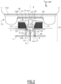
Figure 2 is a cross section schematically showing a possible embodiment of some components of a secondary suspension system used in the bogie according to the invention; -
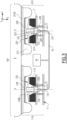
Figure 3 is a further cross section schematically showing a possible embodiment of a secondary suspension system usable in the bogie according to the invention; -
Figure 4 insert B) is a cross section schematically showing an alternative embodiment of some components of a secondary suspension system used in the bogie according to the invention; -
Figure 4 insert A) is an enlarged view of the circled area A offigure 4 insert B). - It should be noted that in the detailed description that follows, identical or similar components, either from a structural and/or functional point of view, have the same reference numerals, regardless of whether they are shown in different embodiments of the present disclosure; it should also be noted that in order to clearly and concisely describe the present disclosure, the drawings may not necessarily be to scale and certain features of the disclosure may be shown in somewhat schematic form.
- Further, when the term "adapted", or "arranged", or "configured", or "shaped", or any equivalent term is used herein while referring to any component as a whole, or to any part of a component, or to a combination of components, it has to be understood that it means and encompasses correspondingly either the structure, and/or configuration and/or form and/or positioning of the related component or part thereof, or combinations, such term refers to.
- In addition, when the term "about" or "substantial" or "substantially" is used herein, it has to be understood as encompassing an actual variation of plus or
minus 5% with respect to an indicated reference value, axis, time or position, and when the terms transversal or transversally are hereby used, they have to be understood as encompassing a direction non-parallel to the reference part(s) or direction(s)/axis they refer to, and perpendicularity has to be considered a specific case of transverse direction. -
Figure 1 is a top view illustrating an exemplary embodiment of a bogie for a railway vehicle, indicated by the overall reference number 1, which comprises a frame 3 including at least afirst side beam 5 and a second side beam 7. - The two
side beams 5 and 7 extend along a longitudinal axis X of the bogie 1 spaced apart from each other. - In the exemplary embodiment illustrated in
figure 1 , the frame 3 comprises also twocross beams 4 and 6 which interconnect to each other the twoside beams 5 and 7. - The bogie 1 comprises also a secondary suspension system, schematically represented in
figure 1 by the overall dottedbox 100, which is located on the frame 3 and includes at least a first suspension assembly, schematically represented infigure 1 by thereference number 110. - As illustrated in more details in the
figures 2 and3 , thefirst suspension assembly 110 includes afirst air spring 112 and a firstauxiliary spring 114 which are positioned at thefirst side beam 5 with thefirst air spring 112 which is positioned below and supports the body of the railway vehicle, schematically represented in thefigures 2 and3 and therein indicated by the capital letter B. - In particular, according to solutions well known or readily available to those skilled in the art, the first air spring is arranged to be pressurized (inflated status), by means of an associated pneumatic circuit not shown in the figures, so that it supports the body B of the railway vehicle above the frame 3. When instead the air spring is in a non-pressurized condition (or deflated status) the
top plate 112A of theair spring 112 is getting in contact with therim 128. In both cases, inflated mode as well as deflated mode of theair spring 112, the support of the body B of the railway vehicle is demanded to the firstauxiliary spring 114. - Usefully, in the bogie 1 according to the invention, the first
auxiliary spring 114 is fixed to anupper side 2 of thefirst side beam 5 underneath and spaced apart from thefirst air spring 112, as illustrated infigures 2 and3 . - In addition, the
first suspension assembly 110 conveniently further comprises at least a first force-transmission mechanism which is operatively connected to the first air andauxiliary springs first air spring 112 to the frame 3, via the firstauxiliary spring 114 itself. - According to a possible embodiment of the bogie 1, as illustrated in the
figures 2 and3 , thefirst side beam 5 conveniently comprises a throughcavity 8 which extends across the thickness of thefirst side beam 5 along a substantially vertical axis Z transversal to the longitudinal axis X, the throughcavity 8 being adapted to house at least part of the first force-transmission mechanism. - In particular, as it will be described in more details hereinafter, the first force-transmission mechanism comprises first hydraulic means which are housed at least partially inside the through
cavity 8 provided in the body of thefirst side beam 5. - In one possible embodiment, as illustrated in more details in
figure 2 , the hydraulic means comprise at least: - a
hydraulic chamber 121, e.g. substantially cylindrical, which is partially filled with afluid 122, e.g. oil, and is placed inside the throughcavity 8; and - a
piston 123 which is connected to arod 125, thepiston 123 being inserted in thehydraulic chamber 121 sliding, upwardly or downwardly, along the substantially vertical axis Z. - In one possible embodiment of the bogie 1 according to the invention, the first force-transmission mechanism conveniently comprises a supporting
body 120 which includes at least: - a
head 120A which is operatively connected to the firstauxiliary spring 114. In particular, thehead 120A is positioned above and arranged to bear against anupper surface 115 of the firstauxiliary spring 114; and - a
shank 124 which extends, within the firstauxiliary spring 114, from thehead 120A downwardly along the substantially vertical axis Z into and at least partly substantially up to theend bottom side 9 of the throughcavity 8. - In particular, the
shank 124 and the throughcavity 8 are mutually arranged so that a first predetermined horizontal gap Y1 is defined between the external surface of theshank 124 and aninternal surface 8A of thefirst side beam 5 delimiting laterally the throughcavity 8. - The first horizontal gap Y1 is measured in an initial and non-displaced position along a third substantially horizontal axis Y transversal to both the longitudinal axis X and the substantially vertical axis Y.
- In particular, this substantially horizontal first gap Z1 allows the first
auxiliary spring 114 to move horizontally with its designed stiffness value. - As illustrated in the
figures 2 and3 , in one possible embodiment the supportingbody 120 includes a throughcavity 126 which is positioned substantially in a central portion of and traverses the entire body of the supportingbody 120 itself, extending, along said substantially vertical axis Z, from thehead 120A up to theend bottom side 124A of theshank 124. - In particular, the central through
cavity 126 of the supportingbody 120 includes a lower part, indicated by thereference number 126A only infigure 3 for the sake of ease of illustration, which is located, at least partly, within the throughcavity 8 of thefirst side beam 5 and forms saidhydraulic chamber 121. - Hence, in the bogie 1 according to the invention the
hydraulic chamber 126 is usefully incorporated directly inside the body of the supportingbody 120. - Further, the central through
cavity 126 of the supportingbody 120 includes an upper part, indicated only infigure 3 by thereference number 126B, which is located at a space comprised between theupper side 2 of thefirst side beam 5 and thefirst air spring 112. - In particular, the free end portion of the
rod 125, opposite to the end side connected to thepiston 123, extends and is movable inside theupper part 126B. - According to this possible embodiment, and as illustrated in the
figures 2 and3 , the first force-transmission mechanism further comprises arim 128 which extends from atop plate 112A of theair spring 112, along the substantially vertical axis Z, downwardly inside theupper part 126B of the central throughcavity 126 of the supportingbody 120. - In an alternative embodiment, as illustrated in
figure 4 insert B), and in more details infigure 4 insert A), therim 128 comprises at its bottom end, arecess 129, e.g. substantially cylindrical, which is adapted to receive inside an end portion of therod 125. - The
recess 129 has a bottom orbase surface 129A which is adapted to get into contact with theupper head surface 127 of therod 125 so that, in operations, when any load, e.g. a vertical force exerted by the body B of the railway vehicle causes therim 128 to slide downwardly, it gets into contact with and pushes downwardly also therod 125 and thepiston 123 connected therewith. - When instead the
piston 123 is moved upwardly by the pressure exerted by the fluid 122, then thepiston 123 moves upwardly also therod 125 which, via the contact with thebottom surface 129A, moves upwardly therim 128 and thus also thetop plate 112A of theair spring 112. - According to a possible embodiment, as illustrated in
figure 4 insert A), therecess 129 comprises aside wall 130 which protrudes from thebottom surface 129A so that a second predetermined substantially horizontal gap Y2, is defined between the external surface of therod 125 and an internal surface of theside wall 130 itself. - Also the second gap Y2 is measured in an initial and non-displaced position along the substantially horizontal axis Y.
- Such second horizontal gap Y2 enables the transfer of horizontal forces exerted by the body B from the
first rim 128 to the first supportingbody 120 and, via the firstauxiliary spring 114, finally to thefirst side beam 5 of the frame 3, while protecting in particular thepiston 123 and its sealings from being damaged by said horizontal forces. - In this way, the wear of the hydraulic components can be reduced and thus their useful lifetime is consequently extended.
- In one possible embodiment, the
secondary suspension system 100 of the bogie 1 according to the invention further includes, as illustrated infigure 3 , at least asecond suspension assembly 210 which is positioned at the second side beam 7. - The
second suspension assembly 210 is substantially identical, functionally and structurally, to thefirst suspension assembly 110, i.e. it comprises, as illustrated infigure 3 , the same components previously described and mutually arranged in the same way, namely a second airfirst spring 212 with atop plate 212A substantially identical to thefirst air spring 112 with itstop plate 112A, a secondauxiliary spring 114 substantially identical to the firstauxiliary spring 114, a second force-transmission mechanism comprising a second supportingbody 220 having a throughcavity 208, with a respectivehydraulic chamber 221 filled with thesame fluid 122, apiston 223 and a rod 225, substantially identical to the corresponding first force-transmission mechanism having the first throughcavity 8 with the first supportingbody 120 and the correspondinghydraulic chamber 121 filled with thesame fluid 122, thepiston 123 and therod 125. Also the same gaps Y1 and Y2 are formed. - Usefully, as shown in
figure 3 , in the bogie 1 according to the invention, the first andsecond suspensions assemblies pipe 10 so that to balance between them at least the vertical forces exerted by the body B of the railway vehicle on the two sides of the frame 3. - In particular, the connecting
pipe 10 has one end inserted into aport 131 provided at the endbottom side 9 of the first supportingbody 120, and the opposite end inserted into acorresponding port 231 provided at theend bottom side 209 of the second supportingbody 220. - In this way, the connecting
pipe 10 puts in fluid communication the firsthydraulic chamber 121 with the secondhydraulic chamber 221. - Further, in another embodiment the
secondary suspension system 100 includes afluid reservoir 20 containing a certain amount offluid 122; thefluid reservoir 20, is connected to and supplies the connectingpipe 10 with the fluid 122 in order to compensate for example any leakage of such fluid or to receive fluid pushed by the piston(s) 123 and/or 125. - In practice, during normal operations, with reference for example to
figure 3 , theair spring 112 is pressurized and provides a suspension for the vehicle body B. When theair spring 112 is, for whatever reason, in a depressurized of deflated status, e.g. during emergency operations, the vehicle body B is lowered towards the frame 3, thus causing therim 128 to slide inwardly inside the first supportingbody 120. - Thus, as previously mentioned, the
rim 128, that is mechanically connected or in any case always in contact with therod 125, pushes downwardly also therod 125 with thepiston 123 connected therewith which pushes the fluid 120 contained into thelower part 126A of thehydraulic chamber 121, e.g. through thefirst port 131 into the connectingpipe 10. - In this way, vertical loads from the body B are transferred by the air spring via the
rim 128 to the hydraulic means, namely therod 125 and thepiston 123 in contact with the fluid 122; then, the hydraulic means transfer such loads to the supportingbody 120 which redirect them onto theauxiliary spring 114 and finally discharged on theside beam 5 of the frame 3. - In turn, horizontal loads are transferred via the
rim 128 to the supportingbody 120 and from it, via theauxiliary spring 114, finally discharged on theside beam 5 of the frame 3. - The same happens with the loads exerted by the body B on the other side beam 7 with the
secondary suspension assembly 210 and its corresponding components when in use. - According to the embodiment illustrated in
figure 3 , if for example the vertical loads exerted on one side of the frame 3, e.g. on thefirst side beam 5 are higher than those exerted on the other side beam 7, the vertical load in excess on thefirst side beam 5 is transferred via the connectingpipe 10 to the second side beam 7. - Indeed, in this case, the
first piston 123 pushes the fluid 122 contained into thelower part 126A of thehydraulic chamber 121 outside through thefirst port 131 into the connectingpipe 10. - The pushing action is thus transferred by the shifted fluid 122 flowing into the connecting
pipe 10 and entering, via thesecond port 231, into the secondhydraulic chamber 221. - In this way, the
piston 223 is pushed upwardly by the pressure exerted by the fluid 122 and moves upwardly also the rod 225; consequently, the rod 225 moves upwardly thesecond rim 228 itself and thus also thetop plate 212A of thesecond air spring 212. - The same happens in a reverse mode if the vertical load initially in excess is exerted on the second side beam 7.
- The rising and lowering movements in opposite directions of the piston 123 (equivalent to those of the piston 223) are indicated in
figure 2 by the arrows ΔZ. - Thanks to this balancing of initially uneven loads, the bogie 1 can easily adapt itself for example to twisted rails, thus substantially preventing or in any case efficiently facing the possibility of derailment.
- Hence, it is evident from the foregoing description that the bogie 1 according to the present invention allows achieving the intended aim since it allows to properly support the loads exerted by the body B of the railway vehicle, while providing an adequate level of protection against possible derailments according to a constructive configuration which is simpler than that of known solutions.
- In particular, in the bogie 1 according to the invention in practice there is defined a kind of hydraulic module and of a spring module, wherein the equipment of the hydraulic module is at least partly sunk directly into the structure of a side beam and is separated from the springs module which is located in the space between the frame 3 and the body of the railway vehicle, with the auxiliary spring also located at the same side beam.
- In this way, it is not necessary to have centralized auxiliary spring systems installed along the cross beams which can therefore maintain a simplified structure, while the reworking of a side beam according to the present invention requires substantially only the realization of a through cavity.
- Further, the position of the hydraulic components incorporated within the structure of a side beam enables a more variable length of the hydraulic chamber and therefore a longer usable piston stroke even when the air spring system is of small size. This useful stroke allows to better obtain the required twist displacements of the car body and to implement a more efficient wheel-wear equalization.
- In addition, the use of the force transmitting mechanism structurally interposed between and operatively linking the air spring with the auxiliary spring and the space saving obtained via the positioning of the components as described, as well as of the intrinsic structure for example of the supporting
body 120, offers the option to implement the same, and in particular its hydraulic components, for different types of air spring systems. - Thus, the bogie 1 according to the invention can be easily used in principle with any suitable type of railway vehicles.
- Hence, as previously indicated, the present invention encompasses also a railway vehicle comprising at least one bogie 1 as previously described, and in particular as defined in the appended claims.
- The bogie 1 and related railway vehicle thus conceived are susceptible of modifications and variations, all of which are within the scope of the inventive concept as defined in particular by the appended claims; for example, in relation to the specific application, some of the components can be differently shaped or positioned, provided that they maintain the functionalities and perform the tasks devised for them within the context of the present invention; the first and
second suspension assemblies pipe 10 andreservoir 20 can be easily duplicated, as for example schematically illustrated infigure 1 ; in such a case, for example only onereservoir 20 can be used for supplying both the two connectingpipes 10; et cetera. - All the details may furthermore be replaced with technically equivalent elements.
Claims (15)
- Bogie (1) for a railway vehicle, comprising:- a frame (3) comprising at least a first side beam (5) and a second side beam (7) which extend along a longitudinal axis (X) of the bogie (1) spaced apart from each other;- a secondary suspension system (100) which is located on the frame (3) and comprises at least a first suspension assembly (110), said first suspension assembly (110) including a first air spring (112) and a first auxiliary spring (114) which are positioned at said first side beam (5), wherein the first air spring (112) is positioned below and is arranged to be pressurized for supporting the body of the railway vehicle (B) above the frame (3);the bogie (1) being characterized in that the first auxiliary spring (114) is fixed to an upper side (2) of said first side beam (5) underneath and spaced apart from the first air spring (112);and in that the first suspension assembly (110) further comprises at least a first force-transmission mechanism (120, 121, 123, 125, 128) which is configured to transmit forces exerted by the body (B) on the first air spring (112) to the frame (3) via the first auxiliary spring (114).
- The bogie (1) according to claim 1, wherein said first side beam (5) comprises a through cavity (8) which extends along a substantially vertical axis (Z) transversal to said longitudinal axis (X) and is adapted to house at least part of said first force-transmission mechanism (120, 121, 123, 125, 128).
- The bogie (1) according to claim 2, wherein said first force-transmission mechanism (120, 121, 123, 125, 128) comprises first hydraulic means (121, 123, 125, 131, 10) which are housed at least partially inside said through cavity (8).
- The bogie (1) according to claim 3, wherein said hydraulic means (121, 123, 125) comprise at least:- a hydraulic chamber (121) which is partially filled with a fluid (122) and is placed together with a port (131) of the supporting body (120) as well as the piping connection (10) at least partly inside said through cavity (8); and- a piston (123) which is connected to a rod (125), said piston (123) being inserted in said hydraulic chamber (121) sliding along said substantially vertical axis (Z).
- The bogie (1) according to one or more of claims 2 to 4, wherein said first force-transmission mechanism (120, 121, 123, 125, 128) comprises a supporting body (120) which includes at least:- a head (120A) which is positioned above and arranged to bear against an upper surface (115) of the first auxiliary spring (114); and- a shank (124), its port (131) and a piping connection (10) which extend at least partly, within the first auxiliary spring (114), from the head (120A) downwardly along said substantially vertical axis (Z) into said through cavity (8) towards the end bottom side (9) of the supporting body (120).
- The bogie (1) according to claim 5, wherein a first predetermined gap (Y1), measured along a substantially horizontal axis (Y) transversal to said longitudinal axis (X) and said substantially vertical axis (Z), is defined between the external surface of the shank (124) and an internal surface (2) of the first side beam (5) delimiting said through cavity (8).
- The bogie (1) according to claim 5 or 6, wherein said supporting body (120) includes a substantially central through cavity (126) which extends, along said substantially vertical axis (Z), from the head (120A) up to the end bottom side (124A) of the shank (124).
- The bogie (1) according to claim 7, wherein said central through cavity (126) of the supporting body (120) includes a lower part (126A) which is located, at least partly, within said through cavity (8) of the first side beam (5) and forms said hydraulic chamber (121).
- The bogie (1) according to claims 4 and 8, wherein said central through cavity (126) of the supporting body (120) includes an upper part (126B) which is located at a space comprised between the upper side (2) of the first side beam (5) and the first air spring (112), and wherein a portion of said rod (125) extends and is movable inside said upper part (126B).
- The bogie (1) according to claim 9, wherein said first force-transmission mechanism further comprises a rim (128) which extends from a top plate (112A) of the air spring (112) downwardly along said substantially vertical axis (Z) inside said upper part (126B) of the central through cavity (126) of the guide member (120).
- The bogie (1) according to claim 10, wherein said rim (128) comprises, at its bottom end, a recess (129) adapted to receive inside an end portion of the rod (125), said recess (129) having a base surface (129A) into contact with an upper head surface (127) of the rod (125).
- The bogie (1) according to claim 11, wherein said recess (129) comprises a side wall (130) which protrudes from said base surface (129A) so that a second predetermined gap (Y2), measured along a substantially horizontal axis (Y) transversal to said longitudinal axis (X) and said substantially vertical axis (Z), is defined between the external surface of the rod (125) and an internal surface of the side wall (130) itself.
- The bogie (1) according to one or more of the previous claims, wherein the secondary suspension system (100) further includes a second suspension assembly (210) which is positioned at said second side beam (7), said first and second suspensions assemblies (110, 210) being in fluid communication to each other via a connecting pipe (10) so that to balance between them at least vertical forces exerted by the body (B) of the railway vehicle on said first and second side beams (5, 7).
- The bogie (1) according to claim 13, wherein the secondary suspension system (100) further includes a fluid reservoir (20) which contains a fluid (122) and is connected to and supplies the connecting pipe (10) with said fluid (122).
- A railway vehicle characterized in that it comprises at least one bogie (1) according to one or more of the previous claims.
Priority Applications (3)
| Application Number | Priority Date | Filing Date | Title |
|---|---|---|---|
| EP22306568.1A EP4357217A1 (en) | 2022-10-17 | 2022-10-17 | Bogie with improved secondary suspension system, and railway vehicle comprising such bogie |
| CA3216186A CA3216186A1 (en) | 2022-10-17 | 2023-10-12 | Bogie with improved secondary suspension system, and railway vehicle comprising such bogie |
| US18/487,833 US20240124034A1 (en) | 2022-10-17 | 2023-10-16 | Bogie with improved secondary suspension system, and railway vehicle comprising such bogie |
Applications Claiming Priority (1)
| Application Number | Priority Date | Filing Date | Title |
|---|---|---|---|
| EP22306568.1A EP4357217A1 (en) | 2022-10-17 | 2022-10-17 | Bogie with improved secondary suspension system, and railway vehicle comprising such bogie |
Publications (1)
| Publication Number | Publication Date |
|---|---|
| EP4357217A1 true EP4357217A1 (en) | 2024-04-24 |
Family
ID=84044050
Family Applications (1)
| Application Number | Title | Priority Date | Filing Date |
|---|---|---|---|
| EP22306568.1A Pending EP4357217A1 (en) | 2022-10-17 | 2022-10-17 | Bogie with improved secondary suspension system, and railway vehicle comprising such bogie |
Country Status (3)
| Country | Link |
|---|---|
| US (1) | US20240124034A1 (en) |
| EP (1) | EP4357217A1 (en) |
| CA (1) | CA3216186A1 (en) |
Citations (6)
| Publication number | Priority date | Publication date | Assignee | Title |
|---|---|---|---|---|
| DE1455159A1 (en) * | 1964-11-05 | 1969-03-27 | Maschf Augsburg Nuernberg Ag | Adjustable gas suspension for laterally movable brackets |
| JPS5421790U (en) * | 1977-07-14 | 1979-02-13 | ||
| EP2353962A1 (en) * | 2010-02-01 | 2011-08-10 | Stadler Bussnang AG | Undercarriage assembly for a rail vehicle |
| EP3006299A1 (en) * | 2014-10-10 | 2016-04-13 | ALSTOM Transport Technologies | A bogie with a secondary suspension having a load balance device |
| CN111267893A (en) * | 2020-03-13 | 2020-06-12 | 中车株洲电力机车有限公司 | Rail vehicle framework |
| CN213948432U (en) * | 2020-12-21 | 2021-08-13 | 中铁轨道交通装备有限公司 | Hydro-pneumatic suspension system suitable for rail vehicle |
-
2022
- 2022-10-17 EP EP22306568.1A patent/EP4357217A1/en active Pending
-
2023
- 2023-10-12 CA CA3216186A patent/CA3216186A1/en active Pending
- 2023-10-16 US US18/487,833 patent/US20240124034A1/en active Pending
Patent Citations (6)
| Publication number | Priority date | Publication date | Assignee | Title |
|---|---|---|---|---|
| DE1455159A1 (en) * | 1964-11-05 | 1969-03-27 | Maschf Augsburg Nuernberg Ag | Adjustable gas suspension for laterally movable brackets |
| JPS5421790U (en) * | 1977-07-14 | 1979-02-13 | ||
| EP2353962A1 (en) * | 2010-02-01 | 2011-08-10 | Stadler Bussnang AG | Undercarriage assembly for a rail vehicle |
| EP3006299A1 (en) * | 2014-10-10 | 2016-04-13 | ALSTOM Transport Technologies | A bogie with a secondary suspension having a load balance device |
| CN111267893A (en) * | 2020-03-13 | 2020-06-12 | 中车株洲电力机车有限公司 | Rail vehicle framework |
| CN213948432U (en) * | 2020-12-21 | 2021-08-13 | 中铁轨道交通装备有限公司 | Hydro-pneumatic suspension system suitable for rail vehicle |
Also Published As
| Publication number | Publication date |
|---|---|
| US20240124034A1 (en) | 2024-04-18 |
| CA3216186A1 (en) | 2024-04-17 |
Similar Documents
| Publication | Publication Date | Title |
|---|---|---|
| US2908230A (en) | Railway car truck | |
| EP3473514B1 (en) | Bolster of bogie | |
| CN102774394B (en) | Rail road car truck with self-steering equipment | |
| AU2010353130A1 (en) | Full side bearing bearing-type railway truck bogie | |
| CA2837575C (en) | Brake beam assembly for a railway car truck | |
| EP3473515B1 (en) | Frame of bogie | |
| CA2213761C (en) | Side bearings for truck bolsters | |
| US20030107161A1 (en) | Spring suspension device | |
| US5611284A (en) | Rail truck suspension and journal housing retention assembly | |
| CN101098808A (en) | railway bogie | |
| CA3000282C (en) | Height control mechanism for a rail vehicle | |
| US7469641B2 (en) | Bolster and spring pockets for use with rail truck | |
| RU77592U1 (en) | TWO-WAY CAR TRUCK | |
| US20240124034A1 (en) | Bogie with improved secondary suspension system, and railway vehicle comprising such bogie | |
| CA1219171A (en) | Single axle suspension system for railroad vehicle | |
| US3439630A (en) | Hydraulically dampered cross equalized trucks | |
| EP0879750B1 (en) | Improvements in bogie trucks for rail vehicles | |
| EP3006299A1 (en) | A bogie with a secondary suspension having a load balance device | |
| CN112849190B (en) | Axle box suspension device and bogie | |
| AU2016244269B2 (en) | Side bearing for railway car truck | |
| CZ2018298A3 (en) | Rail vehicle chassis, especially a freight wagon | |
| CN100450845C (en) | Quick railway goods train bogie | |
| KR100756600B1 (en) | Bogie coil spring elasticity measuring device for rolling stock | |
| KR101315228B1 (en) | Railway bogie conical spring deflection and axial appeal measurement method according to the load and the device | |
| US2861523A (en) | Vertically retractable auxiliary wheels for railroad cars |
Legal Events
| Date | Code | Title | Description |
|---|---|---|---|
| PUAI | Public reference made under article 153(3) epc to a published international application that has entered the european phase |
Free format text: ORIGINAL CODE: 0009012 |
|
| STAA | Information on the status of an ep patent application or granted ep patent |
Free format text: STATUS: THE APPLICATION HAS BEEN PUBLISHED |
|
| STAA | Information on the status of an ep patent application or granted ep patent |
Free format text: STATUS: REQUEST FOR EXAMINATION WAS MADE |
|
| AK | Designated contracting states |
Kind code of ref document: A1 Designated state(s): AL AT BE BG CH CY CZ DE DK EE ES FI FR GB GR HR HU IE IS IT LI LT LU LV MC ME MK MT NL NO PL PT RO RS SE SI SK SM TR |
|
| 17P | Request for examination filed |
Effective date: 20240403 |
|
| RBV | Designated contracting states (corrected) |
Designated state(s): AL AT BE BG CH CY CZ DE DK EE ES FI FR GB GR HR HU IE IS IT LI LT LU LV MC ME MK MT NL NO PL PT RO RS SE SI SK SM TR |
|
| RIN1 | Information on inventor provided before grant (corrected) |
Inventor name: BOETTCHER, ANDREAS |
|
| STAA | Information on the status of an ep patent application or granted ep patent |
Free format text: STATUS: EXAMINATION IS IN PROGRESS |
|
| 17Q | First examination report despatched |
Effective date: 20260312 |