EP4357195A1 - Seat system for a vehicle, vehicle comprising a seat system, and method for operating a seat system - Google Patents
Seat system for a vehicle, vehicle comprising a seat system, and method for operating a seat system Download PDFInfo
- Publication number
- EP4357195A1 EP4357195A1 EP22202539.7A EP22202539A EP4357195A1 EP 4357195 A1 EP4357195 A1 EP 4357195A1 EP 22202539 A EP22202539 A EP 22202539A EP 4357195 A1 EP4357195 A1 EP 4357195A1
- Authority
- EP
- European Patent Office
- Prior art keywords
- seat
- seatbelt
- vehicle
- seat part
- seating position
- Prior art date
- Legal status (The legal status is an assumption and is not a legal conclusion. Google has not performed a legal analysis and makes no representation as to the accuracy of the status listed.)
- Pending
Links
Images




Classifications
-
- B—PERFORMING OPERATIONS; TRANSPORTING
- B60—VEHICLES IN GENERAL
- B60N—SEATS SPECIALLY ADAPTED FOR VEHICLES; VEHICLE PASSENGER ACCOMMODATION NOT OTHERWISE PROVIDED FOR
- B60N2/00—Seats specially adapted for vehicles; Arrangement or mounting of seats in vehicles
- B60N2/02—Seats specially adapted for vehicles; Arrangement or mounting of seats in vehicles the seat or part thereof being movable, e.g. adjustable
- B60N2/04—Seats specially adapted for vehicles; Arrangement or mounting of seats in vehicles the seat or part thereof being movable, e.g. adjustable the whole seat being movable
- B60N2/06—Seats specially adapted for vehicles; Arrangement or mounting of seats in vehicles the seat or part thereof being movable, e.g. adjustable the whole seat being movable slidable
-
- B—PERFORMING OPERATIONS; TRANSPORTING
- B60—VEHICLES IN GENERAL
- B60N—SEATS SPECIALLY ADAPTED FOR VEHICLES; VEHICLE PASSENGER ACCOMMODATION NOT OTHERWISE PROVIDED FOR
- B60N2/00—Seats specially adapted for vehicles; Arrangement or mounting of seats in vehicles
- B60N2/68—Seat frames
- B60N2/688—Particular seat belt attachment and guiding
-
- B—PERFORMING OPERATIONS; TRANSPORTING
- B60—VEHICLES IN GENERAL
- B60N—SEATS SPECIALLY ADAPTED FOR VEHICLES; VEHICLE PASSENGER ACCOMMODATION NOT OTHERWISE PROVIDED FOR
- B60N2/00—Seats specially adapted for vehicles; Arrangement or mounting of seats in vehicles
- B60N2/02—Seats specially adapted for vehicles; Arrangement or mounting of seats in vehicles the seat or part thereof being movable, e.g. adjustable
- B60N2/0224—Non-manual adjustments, e.g. with electrical operation
- B60N2/02246—Electric motors therefor
-
- B—PERFORMING OPERATIONS; TRANSPORTING
- B60—VEHICLES IN GENERAL
- B60N—SEATS SPECIALLY ADAPTED FOR VEHICLES; VEHICLE PASSENGER ACCOMMODATION NOT OTHERWISE PROVIDED FOR
- B60N2/00—Seats specially adapted for vehicles; Arrangement or mounting of seats in vehicles
- B60N2/02—Seats specially adapted for vehicles; Arrangement or mounting of seats in vehicles the seat or part thereof being movable, e.g. adjustable
- B60N2/04—Seats specially adapted for vehicles; Arrangement or mounting of seats in vehicles the seat or part thereof being movable, e.g. adjustable the whole seat being movable
- B60N2/14—Seats specially adapted for vehicles; Arrangement or mounting of seats in vehicles the seat or part thereof being movable, e.g. adjustable the whole seat being movable rotatable, e.g. to permit easy access
- B60N2/143—Seats specially adapted for vehicles; Arrangement or mounting of seats in vehicles the seat or part thereof being movable, e.g. adjustable the whole seat being movable rotatable, e.g. to permit easy access taking a position opposite to the original one
-
- B—PERFORMING OPERATIONS; TRANSPORTING
- B60—VEHICLES IN GENERAL
- B60N—SEATS SPECIALLY ADAPTED FOR VEHICLES; VEHICLE PASSENGER ACCOMMODATION NOT OTHERWISE PROVIDED FOR
- B60N2/00—Seats specially adapted for vehicles; Arrangement or mounting of seats in vehicles
- B60N2/80—Head-rests
- B60N2/806—Head-rests movable or adjustable
- B60N2/838—Tiltable
-
- B—PERFORMING OPERATIONS; TRANSPORTING
- B60—VEHICLES IN GENERAL
- B60N—SEATS SPECIALLY ADAPTED FOR VEHICLES; VEHICLE PASSENGER ACCOMMODATION NOT OTHERWISE PROVIDED FOR
- B60N2/00—Seats specially adapted for vehicles; Arrangement or mounting of seats in vehicles
- B60N2/90—Details or parts not otherwise provided for
- B60N2/995—Lower-leg-rests, e.g. calf-rests
-
- B—PERFORMING OPERATIONS; TRANSPORTING
- B60—VEHICLES IN GENERAL
- B60N—SEATS SPECIALLY ADAPTED FOR VEHICLES; VEHICLE PASSENGER ACCOMMODATION NOT OTHERWISE PROVIDED FOR
- B60N2/00—Seats specially adapted for vehicles; Arrangement or mounting of seats in vehicles
- B60N2/02—Seats specially adapted for vehicles; Arrangement or mounting of seats in vehicles the seat or part thereof being movable, e.g. adjustable
- B60N2002/0204—Seats specially adapted for vehicles; Arrangement or mounting of seats in vehicles the seat or part thereof being movable, e.g. adjustable characterised by the seat or seat part turning about or moving along a non-standard, particular axis, i.e. an axis different from the axis characterising the conventional movement
- B60N2002/0216—Seats specially adapted for vehicles; Arrangement or mounting of seats in vehicles the seat or part thereof being movable, e.g. adjustable characterised by the seat or seat part turning about or moving along a non-standard, particular axis, i.e. an axis different from the axis characterising the conventional movement the seat or seat part turning about or moving along a transversal axis
-
- B—PERFORMING OPERATIONS; TRANSPORTING
- B60—VEHICLES IN GENERAL
- B60N—SEATS SPECIALLY ADAPTED FOR VEHICLES; VEHICLE PASSENGER ACCOMMODATION NOT OTHERWISE PROVIDED FOR
- B60N2/00—Seats specially adapted for vehicles; Arrangement or mounting of seats in vehicles
- B60N2/02—Seats specially adapted for vehicles; Arrangement or mounting of seats in vehicles the seat or part thereof being movable, e.g. adjustable
- B60N2002/0204—Seats specially adapted for vehicles; Arrangement or mounting of seats in vehicles the seat or part thereof being movable, e.g. adjustable characterised by the seat or seat part turning about or moving along a non-standard, particular axis, i.e. an axis different from the axis characterising the conventional movement
- B60N2002/022—Seats specially adapted for vehicles; Arrangement or mounting of seats in vehicles the seat or part thereof being movable, e.g. adjustable characterised by the seat or seat part turning about or moving along a non-standard, particular axis, i.e. an axis different from the axis characterising the conventional movement the seat or seat part turning about or moving along a vertical axis
Definitions
- the present disclosure relates to a seat system for a vehicle comprising a vehicle seat and a frame structure, where the frame structure is connected to a vehicle structure.
- the vehicle seat is pivotably arranged relative to the frame structure around a pivot axis and configured for pivoting around the pivot axis between a first seating position and a second seating position opposite each other.
- the disclosure further relates to a vehicle comprising a seat system and a method for operating a seat system for a vehicle.
- Vehicle seats that can be arranged in different positions are becoming more and more popular in vehicle applications.
- a vehicle seat having a pivoting positioning function is enabling flexible vehicle seating solutions.
- An object of the present disclosure is to provide a seat system for a vehicle, a vehicle comprising a seat system, and a method for operating a seat system for a vehicle, where the previously mentioned problems are avoided.
- This object is at least partly achieved by the features of the independent claims.
- the dependent claims contain further developments of the seat system.
- the disclosure concerns a seat system for a vehicle comprising a vehicle seat and a frame structure, where the frame structure is connected to a vehicle structure.
- the vehicle seat is pivotably arranged relative to the frame structure around a pivot axis and configured for pivoting around the pivot axis between a first seating position and a second seating position opposite each other.
- the vehicle seat comprises a first seat part and a second seat part connected to each other. In the first seating position, the first seat part is forming a backrest and the second seat part is forming a seat platform. In the second seating position, the first seat part is forming a seat platform and the second seat part is forming a backrest.
- the vehicle seat comprises an integrated first seatbelt system arranged in connection to the first seat part, where the first seatbelt system is configured for being worn by a user of the vehicle in the first seating position.
- the vehicle seat comprises an integrated second seatbelt system arranged in connection to the second seat part, where the second seatbelt system is configured for being worn by a user of the vehicle in the second seating position.
- the vehicle seat can be made simple in construction without the need for seatbelt anchoring points in the vehicle structure.
- the integration of the seatbelt systems within the vehicle seat is enabling an efficient design, where the seatbelt systems are flexible to use and simple to adjust when worn by a user of the vehicle, for an optimal seatbelt positioning in different vehicle seat pivoting positions.
- the pivoting vehicle seat where the first seating position and the second seating position are arranged opposite each other, allows a user to change direction of seating position, without compromising with safety.
- the vehicle seat can be made lightweight in construction and simple to adjust compared to traditional solutions.
- the vehicle seat system design is enabling high safety for the user of the vehicle.
- the first seat part comprises a first inner end and a first outer end.
- the first inner end is arranged in connection to the pivot axis.
- the second seat part comprises a second inner end and a second outer end.
- the second inner end is arranged in connection to the pivot axis.
- the respective inner ends are forming sections of the seat parts connected to the pivot axis, enabling the vehicle seat and the seat parts to pivot around the pivot axis for an efficient and simple design of the seat system.
- the first seatbelt system comprises a first seatbelt integrated in the first seat part.
- the first seatbelt is extending from a first inner attachment point arranged in the first seat part in connection to the first inner end, to a first outer attachment point arranged in connection to an outer side of the first seat part at the first inner end via the first outer end.
- the second seatbelt system comprises a second seatbelt integrated in the second seat part.
- the second seatbelt is extending from a second inner attachment point arranged in the second seat part in connection to the second inner end, to a second outer attachment point arranged in connection to an outer side of the second seat part at the second inner end via the second outer end.
- the first seat part comprises a first seatbelt channel extending between the first inner attachment point and the first outer end, where the first seatbelt is extending in the first seatbelt channel.
- the second seat part comprises a second seatbelt channel extending between the second inner attachment point and the second outer end, where the second seatbelt is extending in the second seatbelt channel.
- the first and second seatbelt channels are forming channel structures inside the respective seat parts in which the corresponding seatbelts are allowed to run freely when being used.
- the first inner attachment point is arranged as a seatbelt retractor configured for retracting and releasing the first seatbelt
- the second inner attachment point is arranged as a seatbelt retractor configured for retracting and releasing the second seatbelt.
- the seatbelt retractors are used for a simple and efficient handling of the seatbelts, where the seatbelts can be easily released and retracted when used. With the seatbelt retractors, the first seatbelt can be retracted and released within in the first seatbelt channel from the seatbelt retractor forming the first inner attachment point, and the second seatbelt can be retracted and released within in the second seatbelt channel from the seatbelt retractor forming the second inner attachment point.
- the vehicle seat comprises a seatbelt lock arranged on a lateral side of the vehicle seat in connection to the pivot axis.
- the seatbelt lock is configured for releasably connecting the first seatbelt in the first seating position and releasably connecting the second seatbelt in the second seating position.
- the seatbelt lock is positioned in connection to the pivot axis and arranged on an opposite lateral side of the vehicle seat relative to the first outer attachment point and the second outer attachment point.
- the seatbelt lock is with this positioning efficiently used for both the first seatbelt and the second seatbelt in the respective seating positions.
- the vehicle seat comprises a first outer seat section attached to the first outer end of the first seat part.
- the first outer seat section is pivotably arranged relative to the first seat part, and the first outer seat section is forming a headrest in the first seating position.
- the vehicle seat comprises a second outer seat section attached to the second outer end of the second seat part.
- the second outer seat section is pivotably arranged relative to the second seat part, and the second outer seat section is forming a headrest in the second seating position.
- the outer seat sections are in this way adjustable relative to the corresponding seat parts for an efficient positioning of the adjustable headrest in the respective seating positions.
- each of the first seat part and the second seat part is pivotably arranged relative to the frame structure around the pivot axis.
- the pivotably arranged seat parts are providing a flexible seating solution allowing different seating positions for the user of the vehicle when seated in the vehicle seat.
- the first seat part is individually adjustable relative to the frame structure and relative to the second seat part.
- the second seat part is individually adjustable relative to the frame structure and relative to the first seat part. This is enabling an efficient adjustment of the seat parts independently of each other.
- the first seat part and the second seat part are individually adjustable relative to each other for a flexible seating solution.
- the seat part functioning as the backrest may be adjustable around the pivot axis relative to the seat part functioning as seat platform and vice versa.
- the seat system further comprises a first main actuator and a second main actuator arranged in the vehicle seat.
- the first main actuator is configured for enabling the individual adjustment of the first seat part relative to the frame structure around the pivot axis.
- the second main actuator is configured for enabling the individual adjustment of the second seat part relative to the frame structure around the pivot axis.
- the main actuators are providing an efficient adjustment of the seat parts relative to the frame structure around the pivot axis.
- the first main actuator is arranged as an electric motor
- the second main actuator is arranged as an electric motor.
- the electric motors are providing a simple and efficient individual adjustment of the first and second seat parts relative to the frame structure around the pivot axis.
- the first seat part comprises a first inner sub-section and a first outer sub-section pivotably arranged relative to each other
- the second seat part comprises a second inner sub-section and a second outer sub-section pivotably arranged relative to each other.
- the frame structure is connected to the vehicle structure via a rail structure.
- the rail structure enables a mechanical sliding connection between the frame structure with the vehicle seat and the vehicle structure.
- the rail structure comprises two interconnected rail parts that are linearly slidable relative to each other, where a lower rail is stationary attached to the vehicle structure and an upper rail is fastened to the frame structure.
- the upper rail may be movably arranged in relation to the lower rail in a longitudinal direction of the vehicle, for a convenient adjustment and positioning of the vehicle seat in relation to the vehicle structure.
- two parallel rail structures are used for holding one vehicle seat.
- the disclosure further concerns a vehicle comprising a seat system as described above.
- the disclosure further concerns a method for operating a seat system of a vehicle as described above.
- the method comprises the steps: arranging the vehicle seat in the first seating position for enabling usage of the first seatbelt system, or arranging the vehicle seat in the second seating position for enabling usage of the second seatbelt system.
- the vehicle seat can be made simple in construction without the need for seatbelt anchoring points in the vehicle structure.
- the integration of the seatbelt systems within the vehicle seat is enabling an efficient design, where the seatbelt systems are flexible to use and simple to adjust when worn by a user of the vehicle, for an optimal seatbelt positioning in different vehicle seat pivoting positions.
- the pivoting vehicle seat, where the first seating position and the second seating position are arranged opposite each other allows a user to change direction of seating position, without compromising with safety.
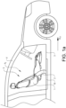
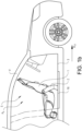
- FIGS 1a-b schematically shows a vehicle V with a seat system S.
- the seat system S comprises a vehicle seat 1 attached to a frame structure 2, and the frame structure 2 is connected to a vehicle structure 3.
- the vehicle structure 3 is a floor structure of an interior compartment of the vehicle V.
- the vehicle structure 3 may be any suitable floor structure or other suitable structural part of the vehicle V, such as a sill structure, a side structure, or a combination of different interior vehicle structures.
- the seat system S is illustrated in connection to a front vehicle seat, but the seat system S may be used also for other vehicle seats.
- the vehicle seat 1 is arranged in a forwards position P F
- the vehicle seat 1b the vehicle seat 1 is arranged in a rearwards position P R .
- the frame structure 2 is in the illustrated embodiment connected to the vehicle structure 3 via a rail structure 16 as shown in figures 1a-b , 2a-c , 3a-b and 4a-b .
- the rail structure 16 enables a mechanical sliding connection between the frame structure 2 with the vehicle seat 1 and the vehicle structure 3.
- the rail structure 16 comprises two interconnected rail parts that are linearly slidable relative to each other, where a lower rail is stationary attached to the vehicle structure 3 and an upper rail is fastened to the frame structure 2.
- the upper rail may be movably arranged in relation to the lower rail in a longitudinal direction D LO of the vehicle V, for a convenient adjustment and positioning of the vehicle seat 1 in relation to the vehicle structure 3.
- two parallel rail structures 16 are used for holding one vehicle seat 1, as shown in for example figures 3a-b .
- the frame structure 2 with the vehicle seat 1 may suitably be moved along the rail structures 16 by means of an electric motor or similar actuating device. In other embodiments, the frame structure 2 with the vehicle seat 1 may be manually adjusted along the rail structures 16.
- the vehicle seat 1 is pivotably arranged relative to the frame structure 2 around a pivot axis A.
- the vehicle seat 1 is arranged for pivoting around the pivot axis A between a first seating position P1, as shown in figures 1a and 2a , and a second seating position P2, as shown in figures 1b and 2c .
- the vehicle seat 1 is attached to the frame structure 2 in two pivoting points on each lateral side of the vehicle seat forming the pivot axis A, where lateral is referring to a lateral direction D LA perpendicular to the longitudinal direction D LO .
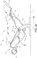
- an intermediate position P INT of the vehicle seat 1 between the first seating position P1 and the second seating position P2 is schematically illustrated.
- the vehicle seat 1 has a shape that allows the vehicle seat 1 to pivot around the pivot axis A without interfering with the frame structure 2.
- the first seating position P1 and the second seating position P2 are arranged opposite each other.
- the first seating position P1 is corresponding to the forwards position P F and the second seating position is corresponding to the rearwards position P R .
- the forwards position P F is a position of the vehicle seat 1, in which a user of the vehicle V is seated in a forwards facing position suitable for driving or operating the vehicle.
- the rearwards position P R is a position of the vehicle seat 1, in which a user of the vehicle V is seated in a rearwards facing position.
- the rearwards position P R is arranged opposite to the forwards position P F , or essentially opposite the forwards position P F .
- the vehicle seat 1 may be enabled to adopt any pivoting position around the pivot axis A between the first position P1 and the second position P2.
- the vehicle seat 1 comprises a first seat part 1a and a second seat part 1b connected to each other.
- the first seat part 1a is forming a backrest B and the second seat part 1b is forming a seat platform SP.
- the first seat part 1a is forming a seat platform SP and the second seat part 1b is forming a backrest B.
- the vehicle seat 1 has a shape that allows the vehicle seat 1 to rotate around the pivot axis A without interfering with the frame structure 2, and the seat parts of the vehicle seat 1 forming the backrest B in the first position P1 and second position P2 can pivot without interfering with the frame structure 2.
- the first seat part 1a comprises a first inner end 5a and a first outer end 6a, and the first inner end 5a is arranged in connection to the pivot axis A.
- the second seat part 1b comprises a second inner end 5b and a second outer end 6b, and the second inner end 5b is arranged in connection to the pivot axis A.
- first seat part 1a and the second seat part 1b are in the illustrated embodiment pivotably arranged relative to the frame structure 2 around the pivot axis A.
- first seat part 1a is suitably individually adjustable relative to the frame structure 2 and relative to the second seat part 1b.
- the second seat part 1b is suitably individually adjustable relative to the frame structure 2 and relative to the first seat part 1a.
- This adjustable configuration is enabling individual positioning of the first seat part 1a and the second seat part 1b relative to each other for a flexible seating solution allowing different seating positions for the user of the vehicle V when seated in the vehicle seat 1, where the seat part functioning as the backrest B may be adjustable around the pivot axis A relative to the seat part functioning as seat platform SP and vice versa.
- the vehicle seat 1 further comprises a first outer seat section 13a attached to the first outer end 6a of the first seat part 1a.
- the first outer seat section 13a is pivotably arranged relative to the first seat part 1a, as indicated with the arrow in figure 2a .
- the first outer section 13a and the first outer end 6a of the first seat part 1a are suitably connected to each other via a pivoting joint, enabling adjustment of the first outer seat section 13a in different positions.
- the first outer seat section 13a is in this way forming an adjustable headrest H in the first seating position P1.
- the first outer section 13a may be manually adjustable relative to the first seat part 1a, or alternatively the first outer section 13a may be adjustable relative to the first seat part 1a via suitable actuator means enabling an efficient positioning of the adjustable headrest H in the first seating position P1.
- the actuator may be arranged as an electric motor or a linear actuator integrated in the first seat part 1a or in the first outer section 13a.
- the vehicle seat 1 further comprises a second outer seat section 13b attached to the second outer end 6b of the second seat part 1b.
- the second outer seat section 13b is pivotably arranged relative to the second seat part 1b as indicated with the arrow in figure 2c .
- the second outer section 13b and the second outer end 6b of the second seat part 1b are suitably connected to each other via a pivoting joint, enabling adjustment of the second outer seat section 13b in different positions.
- the second outer seat section 13b is in this way forming an adjustable headrest H in the second seating position P2.
- the second outer section 13b may be manually adjustable relative to the second seat part 1b, or alternatively the second outer section 13b may be adjustable relative to the second seat part 1b via suitable actuator means enabling an efficient positioning of the adjustable headrest H in the second seating position P2.
- the actuator may be arranged as an electric motor or a linear actuator integrated in the second seat part 1b or in the second outer section 13b.
- the first seat part 1a comprises a first inner sub-section 14a and a first outer sub-section 15a pivotably arranged relative to each other.
- the first inner sub-section 14a and the first outer sub-section 15a are individually adjustable relative to each other.
- This adjustable configuration is enabling individual positioning of the first seat part 1a, when forming the backrest B or the seat platform SP in the respective seating positions, for a flexible seating solution allowing different seating positions for the user of the vehicle V when seated in the vehicle seat 1.
- the first inner sub-section 14a and the first outer sub-section 15a are suitably connected to each other via a pivoting joint for manual adjustment, or electrical adjustment via suitable actuator means enabling an efficient positioning of the sub-sections relative to each other.
- the second seat part 1b comprises a second inner sub-section 14b and a second outer sub-section 15b pivotably arranged relative to each other.
- the second inner sub-section 14b and the second outer sub-section 15b are individually adjustable relative to each other.
- This adjustable configuration is enabling individual positioning of the second seat part 1b, when forming the backrest B or the seat platform SP in the respective seating positions, for a flexible seating solution allowing different seating positions for the user of the vehicle V when seated in the vehicle seat 1.
- the second inner sub-section 14b and the second outer sub-section 15b are suitably connected to each other via a pivoting joint for manual adjustment, or electrical adjustment via suitable actuator means enabling an efficient positioning of the sub-sections relative to each other.
- the seat system S further comprises a first main actuator 12a and a second main actuator 12b arranged in the vehicle seat 1.
- the first main actuator 12a is configured for enabling the individual adjustment of the first seat part 1a relative to the frame structure 2 around the pivot axis A.
- the second main actuator 12b is configured for enabling the individual adjustment of the second seat part 1b relative to the frame structure 2 around the pivot axis A.
- the first main actuator 12a and the second main actuator 12b are arranged as electric motors integrated in the vehicle seat 1, where the first main actuator 12a is integrated in the first seat part 1a and the second main actuator is integrated in the second seat part 1b, as schematically indicated in figure 4a .
- the vehicle seat 1 is suitably connected to a control unit for controlling the positioning of the vehicle seat 1.
- the vehicle seat 1 comprises an integrated first seatbelt system 4a arranged in connection to the first seat part 1a, as shown in for example figures 2a-c , 3a-b and 4a-b, and the first seatbelt system 4a is configured for being worn by a user of the vehicle V in the first seating position P1.
- the first seatbelt system 4a comprises a first seatbelt 7a integrated in the first seat part 1a.
- the first seatbelt 7a is extending from a first inner attachment point 8a arranged in the first seat part 1a in connection to the first inner end 5a to a first outer attachment point 9a via the first outer end 6a.
- the first inner attachment point 8a is arranged within the first seat part 1a, and the first inner attachment point 8a is establishing a firm connection between the first seatbelt 7a and the first seat part 1a for a secure inner anchoring of the first seatbelt 7a to the vehicle seat 1.
- the first inner attachment point 8a is suitably arranged as a seatbelt retractor, enabling a rolled-up configuration of the inner part of the first seatbelt 7a for retracting and releasing the first seatbelt 7a.
- the first outer attachment point 9a is arranged in connection to an outer side So of the first seat part 1a at the first inner end 5a.
- the first outer attachment point 9a is establishing a firm connection between the first seatbelt 7a and the first seat part 1a for a secure outer anchoring of the first seatbelt 7a to the vehicle seat 1.
- the first seat part 1a comprises a first seatbelt channel 10a extending between the first inner attachment point 8a and the first outer end 6a, and the first seatbelt 7a is extending in the first seatbelt channel 10a, as shown in figures 4a-b .
- the first seatbelt channel 10a is forming a channel structure inside the first seat part 1a in which the first seatbelt 7a is allowed to run freely when retracted into the seatbelt retractor or released from the seatbelt retractor. In this way, the first seatbelt 7a can be retracted and released within in the first seatbelt channel 10a from the seatbelt retractor forming the first inner attachment point 8a.
- the vehicle seat 1 comprises an integrated second seatbelt system 4b arranged in connection to the second seat part 1b, as shown in for example figures 2a-c , 3a-b and 4a-b, and the second seatbelt system 4b is configured for being worn by a user of the vehicle V in the second seating position P2.
- the second seatbelt system 4b comprises a second seatbelt 7b integrated in the second seat part 1b.
- the second seatbelt 7b is extending from a second inner attachment point 8b arranged in the second seat part 1b in connection to the second inner end 5b to a second outer attachment point 9b via the second outer end 6b.
- the second inner attachment point 8b is arranged within the second seat part 1b, and the second inner attachment point 8b is establishing a firm connection between the second seatbelt 7b and the second seat part 1b for a secure inner anchoring of the second seatbelt 7b to the vehicle seat 1.
- the second inner attachment point 8b is suitably arranged as a seatbelt retractor, enabling a rolled-up configuration of the inner part of the second seatbelt 7b for retracting and releasing the second seatbelt 7b.
- the second outer attachment point 9b is arranged in connection to an outer side So of the second seat part 1b at the second inner end 5b.
- the second outer attachment point 9b is establishing a firm connection between the second seatbelt 7b and the second seat part 1b for a secure outer anchoring of the second seatbelt 7b to the vehicle seat 1.
- the second seat part 1b comprises a second seatbelt channel 10b extending between the second inner attachment point 8b and the second outer end 6b, and the second seatbelt 7b is extending in the second seatbelt channel 10b, as shown in figures 4a-b .
- the second seatbelt channel 10b is forming a channel structure inside the second seat part 1b in which the second seatbelt 7b is allowed to run freely when retracted into the seatbelt retractor or released from the seatbelt retractor. In this way, the second seatbelt 7b can be retracted and released within in the second seatbelt channel 10b from the seatbelt retractor forming the second inner attachment point 8b.
- first outer attachment point 9a and the second outer attachment point 9b are arranged as a common anchoring point for the first seatbelt 7a and the second seatbelt 7b. It should however be understood that in other non-illustrated embodiments, the first outer attachment point 9a and the second outer attachment point 9b may be arranged separated from each other.
- the vehicle seat 1 comprises a seatbelt lock 11 arranged on a lateral side of the vehicle seat 1 in connection to the pivot axis A.
- the seatbelt lock 11 is used for connecting both the first seatbelt 7a and the second seatbelt 7b, and the seatbelt lock 11 is arranged on an opposite lateral side from the first outer attachment point 9a and the second outer attachment point 9b.
- the seatbelt lock 11 is configured for releasably connecting the first seatbelt 7a in the first seating position P1 and releasably connecting the second seatbelt 7b in the second seating position P2.
- the seatbelt lock 11 is positioned in connection to the pivot axis A and arranged on an opposite lateral side of the vehicle seat 1 relative to the first outer attachment point 9a and the second outer attachment point 9b, for a convenient attachment of the first seatbelt 7a or the second seatbelt 7b respectively.
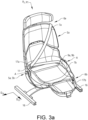
- a first seatbelt lock tongue 17a is arranged on the first seatbelt 7a, and the first seatbelt lock tongue 17a is configured for being releasably connected to the seatbelt lock 11 in the first seating position P1, as illustrated in figure 3a .
- the first seatbelt 7a is configured for being releasably connected to the seatbelt lock 11 via the first seatbelt lock tongue 17a in the first seating position P1.
- the first seatbelt lock tongue 17a is allowed to slide along the first seatbelt 7a in a conventional manner.
- a second seatbelt lock tongue 17b is arranged on the second seatbelt 7b, and the second seatbelt lock tongue 17b is configured for being releasably connected to the seatbelt lock 11 in the second seating position P2, as illustrated in figure 3b .
- the second seatbelt 7b is configured for being releasably connected to the seatbelt lock 11 via the second seatbelt lock tongue 17b in the second seating position P2.
- the second seatbelt lock tongue 17b is allowed to slide along the second seatbelt 7b in a conventional manner.
- the vehicle seat 1 When the vehicle seat 1 is arranged in the first seating position P1, usage of the first seatbelt system 4a is enabled due to the position of the vehicle seat 1.
- the first seatbelt 7a can be secured across the chest and hips of the user.
- the first seatbelt 7a is arranged in a traditional way across the user with a section of the first seatbelt 7a extending across the hips and another section extending across the chest, as understood from the position of the first seatbelt 7a shown in figure 3a .
- the first seatbelt 7a When the first seatbelt 7a is released from the seatbelt retractor forming the first inner attachment point 8a, it may be extended from the first seatbelt channel 10a and arranged across the body of the user. The user may thereafter simply lock the first seatbelt lock tongue 17a to the seatbelt lock 11 for a secure attachment of the first seatbelt 7a. To unlock the first seatbelt 7a, the user is disconnecting the first seatbelt lock tongue 17a from the seatbelt lock 11, and the first seatbelt 7a may then be partly retracted into the seatbelt retractor via the first seatbelt channel 10a into the position shown in figures 2a and 4a .
- the second seatbelt 7b can be secured across the chest and hips of the user.
- the second seatbelt 7b is arranged in a traditional way across the user with a section of the second seatbelt 7b extending across the hips and another section extending across the chest, as understood from the position of the second seatbelt 7b shown in figure 3b .
- the second seatbelt 7b When the second seatbelt 7b is released from the seatbelt retractor forming the second inner attachment point 8b, it may be extended from the second seatbelt channel 10b and arranged across the body of the user. The user may thereafter simply lock the second seatbelt lock tongue 17b to the seatbelt lock 11 for a secure attachment of the second seatbelt 7b. To unlock the second seatbelt 7b, the user is disconnecting the second seatbelt lock tongue 17b from the seatbelt lock 11, and the second seatbelt 7b may then be partly retracted into the seatbelt retractor via the second seatbelt channel 10b into the position indicated in figure 2c .
Landscapes
- Engineering & Computer Science (AREA)
- Aviation & Aerospace Engineering (AREA)
- Transportation (AREA)
- Mechanical Engineering (AREA)
- Seats For Vehicles (AREA)
Abstract
A seat system for a vehicle comprising a vehicle seat and a frame structure, where the frame structure is connected to a vehicle structure. The vehicle seat is pivotably arranged relative to the frame structure around a pivot axis and configured for pivoting around the pivot axis between a first seating position and a second seating position opposite each other. The vehicle seat comprises a first seat part and a second seat part connected to each other. In the first seating position, the first seat part is forming a backrest and the second seat part is forming a seat platform. In the second seating position, the first seat part is forming a seat platform and the second seat part is forming a backrest. The vehicle seat comprises an integrated first seatbelt system arranged in connection to the first seat part, where the first seatbelt system is configured for being worn by a user of the vehicle in the first seating position. The vehicle seat comprises an integrated second seatbelt system arranged in connection to the second seat part, where the second seatbelt system is configured for being worn by a user of the vehicle in the second seating position.
Description
- The present disclosure relates to a seat system for a vehicle comprising a vehicle seat and a frame structure, where the frame structure is connected to a vehicle structure. The vehicle seat is pivotably arranged relative to the frame structure around a pivot axis and configured for pivoting around the pivot axis between a first seating position and a second seating position opposite each other. The disclosure further relates to a vehicle comprising a seat system and a method for operating a seat system for a vehicle.
- Vehicle seats that can be arranged in different positions are becoming more and more popular in vehicle applications. A vehicle seat having a pivoting positioning function is enabling flexible vehicle seating solutions.
- However, traditional vehicle seat systems with pivoting seat configurations commonly have complex constructions, which may be a drawback when the vehicle seat is exerted to forces in a vehicle impact event. Traditional seatbelt arrangements in connection to the pivoting seat are non-flexible and difficult to adjust when worn by a user of the vehicle for an optimal seatbelt positioning in different vehicle seat pivoting positions. The complex and non-flexible designs are resulting in heavy and costly constructions of the seat systems to achieve desired performance.
- There is thus a need for an improved pivoting vehicle seat system having a simple and efficient design that is providing high safety for the user of the vehicle.
- An object of the present disclosure is to provide a seat system for a vehicle, a vehicle comprising a seat system, and a method for operating a seat system for a vehicle, where the previously mentioned problems are avoided. This object is at least partly achieved by the features of the independent claims. The dependent claims contain further developments of the seat system.
- The disclosure concerns a seat system for a vehicle comprising a vehicle seat and a frame structure, where the frame structure is connected to a vehicle structure. The vehicle seat is pivotably arranged relative to the frame structure around a pivot axis and configured for pivoting around the pivot axis between a first seating position and a second seating position opposite each other. The vehicle seat comprises a first seat part and a second seat part connected to each other. In the first seating position, the first seat part is forming a backrest and the second seat part is forming a seat platform. In the second seating position, the first seat part is forming a seat platform and the second seat part is forming a backrest. The vehicle seat comprises an integrated first seatbelt system arranged in connection to the first seat part, where the first seatbelt system is configured for being worn by a user of the vehicle in the first seating position. The vehicle seat comprises an integrated second seatbelt system arranged in connection to the second seat part, where the second seatbelt system is configured for being worn by a user of the vehicle in the second seating position.
- Advantages with these features are that with the two integrated seatbelt systems, the vehicle seat can be made simple in construction without the need for seatbelt anchoring points in the vehicle structure. The integration of the seatbelt systems within the vehicle seat is enabling an efficient design, where the seatbelt systems are flexible to use and simple to adjust when worn by a user of the vehicle, for an optimal seatbelt positioning in different vehicle seat pivoting positions. The pivoting vehicle seat, where the first seating position and the second seating position are arranged opposite each other, allows a user to change direction of seating position, without compromising with safety. The vehicle seat can be made lightweight in construction and simple to adjust compared to traditional solutions. The vehicle seat system design is enabling high safety for the user of the vehicle.
- In one embodiment, the first seat part comprises a first inner end and a first outer end. The first inner end is arranged in connection to the pivot axis. The second seat part comprises a second inner end and a second outer end. The second inner end is arranged in connection to the pivot axis. The respective inner ends are forming sections of the seat parts connected to the pivot axis, enabling the vehicle seat and the seat parts to pivot around the pivot axis for an efficient and simple design of the seat system.
- In one embodiment, the first seatbelt system comprises a first seatbelt integrated in the first seat part. The first seatbelt is extending from a first inner attachment point arranged in the first seat part in connection to the first inner end, to a first outer attachment point arranged in connection to an outer side of the first seat part at the first inner end via the first outer end. The second seatbelt system comprises a second seatbelt integrated in the second seat part. The second seatbelt is extending from a second inner attachment point arranged in the second seat part in connection to the second inner end, to a second outer attachment point arranged in connection to an outer side of the second seat part at the second inner end via the second outer end. With these seatbelt system configurations, the seatbelts can be fully integrated in the vehicle seats for a highly flexible seating solution.
- In one embodiment, the first seat part comprises a first seatbelt channel extending between the first inner attachment point and the first outer end, where the first seatbelt is extending in the first seatbelt channel. The second seat part comprises a second seatbelt channel extending between the second inner attachment point and the second outer end, where the second seatbelt is extending in the second seatbelt channel. The first and second seatbelt channels are forming channel structures inside the respective seat parts in which the corresponding seatbelts are allowed to run freely when being used.
- In one embodiment, the first inner attachment point is arranged as a seatbelt retractor configured for retracting and releasing the first seatbelt, and the second inner attachment point is arranged as a seatbelt retractor configured for retracting and releasing the second seatbelt. The seatbelt retractors are used for a simple and efficient handling of the seatbelts, where the seatbelts can be easily released and retracted when used. With the seatbelt retractors, the first seatbelt can be retracted and released within in the first seatbelt channel from the seatbelt retractor forming the first inner attachment point, and the second seatbelt can be retracted and released within in the second seatbelt channel from the seatbelt retractor forming the second inner attachment point.
- In one embodiment, the vehicle seat comprises a seatbelt lock arranged on a lateral side of the vehicle seat in connection to the pivot axis. The seatbelt lock is configured for releasably connecting the first seatbelt in the first seating position and releasably connecting the second seatbelt in the second seating position.
- In one embodiment, the seatbelt lock is positioned in connection to the pivot axis and arranged on an opposite lateral side of the vehicle seat relative to the first outer attachment point and the second outer attachment point. The seatbelt lock is with this positioning efficiently used for both the first seatbelt and the second seatbelt in the respective seating positions.
- In one embodiment, the vehicle seat comprises a first outer seat section attached to the first outer end of the first seat part. The first outer seat section is pivotably arranged relative to the first seat part, and the first outer seat section is forming a headrest in the first seating position. The vehicle seat comprises a second outer seat section attached to the second outer end of the second seat part. The second outer seat section is pivotably arranged relative to the second seat part, and the second outer seat section is forming a headrest in the second seating position. The outer seat sections are in this way adjustable relative to the corresponding seat parts for an efficient positioning of the adjustable headrest in the respective seating positions.
- In one embodiment, each of the first seat part and the second seat part is pivotably arranged relative to the frame structure around the pivot axis. The pivotably arranged seat parts are providing a flexible seating solution allowing different seating positions for the user of the vehicle when seated in the vehicle seat.
- In one embodiment, the first seat part is individually adjustable relative to the frame structure and relative to the second seat part. The second seat part is individually adjustable relative to the frame structure and relative to the first seat part. This is enabling an efficient adjustment of the seat parts independently of each other. The first seat part and the second seat part are individually adjustable relative to each other for a flexible seating solution. The seat part functioning as the backrest may be adjustable around the pivot axis relative to the seat part functioning as seat platform and vice versa.
- In one embodiment, the seat system further comprises a first main actuator and a second main actuator arranged in the vehicle seat. The first main actuator is configured for enabling the individual adjustment of the first seat part relative to the frame structure around the pivot axis. The second main actuator is configured for enabling the individual adjustment of the second seat part relative to the frame structure around the pivot axis. The main actuators are providing an efficient adjustment of the seat parts relative to the frame structure around the pivot axis.
- In one embodiment, the first main actuator is arranged as an electric motor, and the second main actuator is arranged as an electric motor. The electric motors are providing a simple and efficient individual adjustment of the first and second seat parts relative to the frame structure around the pivot axis.
- In one embodiment, the first seat part comprises a first inner sub-section and a first outer sub-section pivotably arranged relative to each other, and/or the second seat part comprises a second inner sub-section and a second outer sub-section pivotably arranged relative to each other. This adjustable configuration is enabling individual positioning of the respective first seat parts when forming the backrest or the seat platform in the respective seating positions, for a flexible seating solution allowing different seating positions for the user of the vehicle when seated in the vehicle seat.
- In one embodiment, the frame structure is connected to the vehicle structure via a rail structure. The rail structure enables a mechanical sliding connection between the frame structure with the vehicle seat and the vehicle structure. Suitably, the rail structure comprises two interconnected rail parts that are linearly slidable relative to each other, where a lower rail is stationary attached to the vehicle structure and an upper rail is fastened to the frame structure. The upper rail may be movably arranged in relation to the lower rail in a longitudinal direction of the vehicle, for a convenient adjustment and positioning of the vehicle seat in relation to the vehicle structure. Usually, two parallel rail structures are used for holding one vehicle seat.
- The disclosure further concerns a vehicle comprising a seat system as described above.
- The disclosure further concerns a method for operating a seat system of a vehicle as described above. The method comprises the steps: arranging the vehicle seat in the first seating position for enabling usage of the first seatbelt system, or arranging the vehicle seat in the second seating position for enabling usage of the second seatbelt system.
- Advantages with these steps are that with the two integrated seatbelt systems, the vehicle seat can be made simple in construction without the need for seatbelt anchoring points in the vehicle structure. The integration of the seatbelt systems within the vehicle seat is enabling an efficient design, where the seatbelt systems are flexible to use and simple to adjust when worn by a user of the vehicle, for an optimal seatbelt positioning in different vehicle seat pivoting positions. The pivoting vehicle seat, where the first seating position and the second seating position are arranged opposite each other allows a user to change direction of seating position, without compromising with safety.
- The disclosure will be described in detail in the following, with reference to the attached drawings, in which
- Fig. 1a-b
- show schematically, in side views, a vehicle with a seat system having a vehicle seat arranged in a forwards position and in a rearwards position,
- Fig. 2a-c
- show schematically, in side views, the seat system with the vehicle seat arranged in a first seating position, in an intermediate position, and in a second seating position,
- Fig. 3a-b
- show schematically, in perspective views, the seat system with the vehicle seat arranged in the first seating position and in the second seating position, and
- Fig. 4a-b
- show schematically, in a perspective view and in a side view, an internal configuration of the vehicle seat.
- Various aspects of the disclosure will hereinafter be described in conjunction with the appended drawings to illustrate and not to limit the disclosure, wherein like designations denote like elements, and variations of the described aspects are not restricted to the specifically shown embodiments, but are applicable on other variations of the disclosure.
-
Figures 1a-b schematically shows a vehicle V with a seat system S. The seat system S comprises avehicle seat 1 attached to aframe structure 2, and theframe structure 2 is connected to avehicle structure 3. In the shown embodiment, thevehicle structure 3 is a floor structure of an interior compartment of the vehicle V. However, thevehicle structure 3 may be any suitable floor structure or other suitable structural part of the vehicle V, such as a sill structure, a side structure, or a combination of different interior vehicle structures. Infigures 1a-b , the seat system S is illustrated in connection to a front vehicle seat, but the seat system S may be used also for other vehicle seats. Infigure 1a , thevehicle seat 1 is arranged in a forwards position PF, and infigure 1b , thevehicle seat 1 is arranged in a rearwards position PR. - The
frame structure 2 is in the illustrated embodiment connected to thevehicle structure 3 via arail structure 16 as shown infigures 1a-b ,2a-c ,3a-b and4a-b . Therail structure 16 enables a mechanical sliding connection between theframe structure 2 with thevehicle seat 1 and thevehicle structure 3. Suitably, therail structure 16 comprises two interconnected rail parts that are linearly slidable relative to each other, where a lower rail is stationary attached to thevehicle structure 3 and an upper rail is fastened to theframe structure 2. The upper rail may be movably arranged in relation to the lower rail in a longitudinal direction DLO of the vehicle V, for a convenient adjustment and positioning of thevehicle seat 1 in relation to thevehicle structure 3. Usually, twoparallel rail structures 16 are used for holding onevehicle seat 1, as shown in for examplefigures 3a-b . Theframe structure 2 with thevehicle seat 1 may suitably be moved along therail structures 16 by means of an electric motor or similar actuating device. In other embodiments, theframe structure 2 with thevehicle seat 1 may be manually adjusted along therail structures 16. - As illustrated in
figures 2a-b , thevehicle seat 1 is pivotably arranged relative to theframe structure 2 around a pivot axis A. Thevehicle seat 1 is arranged for pivoting around the pivot axis A between a first seating position P1, as shown infigures 1a and2a , and a second seating position P2, as shown infigures 1b and2c . In the illustrated embodiment, thevehicle seat 1 is attached to theframe structure 2 in two pivoting points on each lateral side of the vehicle seat forming the pivot axis A, where lateral is referring to a lateral direction DLA perpendicular to the longitudinal direction DLO. Infigure 2b , an intermediate position PINT of thevehicle seat 1 between the first seating position P1 and the second seating position P2 is schematically illustrated. Thevehicle seat 1 has a shape that allows thevehicle seat 1 to pivot around the pivot axis A without interfering with theframe structure 2. - As understood from the figures, the first seating position P1 and the second seating position P2 are arranged opposite each other. In the illustrated embodiment, the first seating position P1 is corresponding to the forwards position PF and the second seating position is corresponding to the rearwards position PR. The forwards position PF is a position of the
vehicle seat 1, in which a user of the vehicle V is seated in a forwards facing position suitable for driving or operating the vehicle. The rearwards position PR is a position of thevehicle seat 1, in which a user of the vehicle V is seated in a rearwards facing position. The rearwards position PR is arranged opposite to the forwards position PF, or essentially opposite the forwards position PF. Thevehicle seat 1 may be enabled to adopt any pivoting position around the pivot axis A between the first position P1 and the second position P2. - As shown in for example
figures 2a-c , thevehicle seat 1 comprises afirst seat part 1a and asecond seat part 1b connected to each other. In the first seating position P1, thefirst seat part 1a is forming a backrest B and thesecond seat part 1b is forming a seat platform SP. In the second seating position P2, thefirst seat part 1a is forming a seat platform SP and thesecond seat part 1b is forming a backrest B. As described above, thevehicle seat 1 has a shape that allows thevehicle seat 1 to rotate around the pivot axis A without interfering with theframe structure 2, and the seat parts of thevehicle seat 1 forming the backrest B in the first position P1 and second position P2 can pivot without interfering with theframe structure 2. - The
first seat part 1a comprises a firstinner end 5a and a first outer end 6a, and the firstinner end 5a is arranged in connection to the pivot axis A. Thesecond seat part 1b comprises a secondinner end 5b and a secondouter end 6b, and the secondinner end 5b is arranged in connection to the pivot axis A. - Each of the
first seat part 1a and thesecond seat part 1b is in the illustrated embodiment pivotably arranged relative to theframe structure 2 around the pivot axis A. Further, thefirst seat part 1a is suitably individually adjustable relative to theframe structure 2 and relative to thesecond seat part 1b. Thesecond seat part 1b is suitably individually adjustable relative to theframe structure 2 and relative to thefirst seat part 1a. This adjustable configuration is enabling individual positioning of thefirst seat part 1a and thesecond seat part 1b relative to each other for a flexible seating solution allowing different seating positions for the user of the vehicle V when seated in thevehicle seat 1, where the seat part functioning as the backrest B may be adjustable around the pivot axis A relative to the seat part functioning as seat platform SP and vice versa. - As shown in for example
figures 2a-c , thevehicle seat 1 further comprises a firstouter seat section 13a attached to the first outer end 6a of thefirst seat part 1a. The firstouter seat section 13a is pivotably arranged relative to thefirst seat part 1a, as indicated with the arrow infigure 2a . The firstouter section 13a and the first outer end 6a of thefirst seat part 1a are suitably connected to each other via a pivoting joint, enabling adjustment of the firstouter seat section 13a in different positions. The firstouter seat section 13a is in this way forming an adjustable headrest H in the first seating position P1. The firstouter section 13a may be manually adjustable relative to thefirst seat part 1a, or alternatively the firstouter section 13a may be adjustable relative to thefirst seat part 1a via suitable actuator means enabling an efficient positioning of the adjustable headrest H in the first seating position P1. The actuator may be arranged as an electric motor or a linear actuator integrated in thefirst seat part 1a or in the firstouter section 13a. - As shown in for example
figures 2a-c , thevehicle seat 1 further comprises a secondouter seat section 13b attached to the secondouter end 6b of thesecond seat part 1b. The secondouter seat section 13b is pivotably arranged relative to thesecond seat part 1b as indicated with the arrow infigure 2c . The secondouter section 13b and the secondouter end 6b of thesecond seat part 1b are suitably connected to each other via a pivoting joint, enabling adjustment of the secondouter seat section 13b in different positions. The secondouter seat section 13b is in this way forming an adjustable headrest H in the second seating position P2. The secondouter section 13b may be manually adjustable relative to thesecond seat part 1b, or alternatively the secondouter section 13b may be adjustable relative to thesecond seat part 1b via suitable actuator means enabling an efficient positioning of the adjustable headrest H in the second seating position P2. The actuator may be arranged as an electric motor or a linear actuator integrated in thesecond seat part 1b or in the secondouter section 13b. - As shown in for example
figures 2a-c , thefirst seat part 1a comprises a firstinner sub-section 14a and a firstouter sub-section 15a pivotably arranged relative to each other. In this way, the firstinner sub-section 14a and the firstouter sub-section 15a are individually adjustable relative to each other. This adjustable configuration is enabling individual positioning of thefirst seat part 1a, when forming the backrest B or the seat platform SP in the respective seating positions, for a flexible seating solution allowing different seating positions for the user of the vehicle V when seated in thevehicle seat 1. The firstinner sub-section 14a and the firstouter sub-section 15a are suitably connected to each other via a pivoting joint for manual adjustment, or electrical adjustment via suitable actuator means enabling an efficient positioning of the sub-sections relative to each other. - As shown in for example
figures 2a-c , thesecond seat part 1b comprises a secondinner sub-section 14b and a secondouter sub-section 15b pivotably arranged relative to each other. In this way, the secondinner sub-section 14b and the secondouter sub-section 15b are individually adjustable relative to each other. This adjustable configuration is enabling individual positioning of thesecond seat part 1b, when forming the backrest B or the seat platform SP in the respective seating positions, for a flexible seating solution allowing different seating positions for the user of the vehicle V when seated in thevehicle seat 1. The secondinner sub-section 14b and the secondouter sub-section 15b are suitably connected to each other via a pivoting joint for manual adjustment, or electrical adjustment via suitable actuator means enabling an efficient positioning of the sub-sections relative to each other. - The seat system S further comprises a first
main actuator 12a and a secondmain actuator 12b arranged in thevehicle seat 1. The firstmain actuator 12a is configured for enabling the individual adjustment of thefirst seat part 1a relative to theframe structure 2 around the pivot axis A. The secondmain actuator 12b is configured for enabling the individual adjustment of thesecond seat part 1b relative to theframe structure 2 around the pivot axis A. Suitably, the firstmain actuator 12a and the secondmain actuator 12b are arranged as electric motors integrated in thevehicle seat 1, where the firstmain actuator 12a is integrated in thefirst seat part 1a and the second main actuator is integrated in thesecond seat part 1b, as schematically indicated infigure 4a . - The
vehicle seat 1 is suitably connected to a control unit for controlling the positioning of thevehicle seat 1. - The
vehicle seat 1 comprises an integratedfirst seatbelt system 4a arranged in connection to thefirst seat part 1a, as shown in for examplefigures 2a-c ,3a-b and 4a-b, and thefirst seatbelt system 4a is configured for being worn by a user of the vehicle V in the first seating position P1. - The
first seatbelt system 4a comprises afirst seatbelt 7a integrated in thefirst seat part 1a. Thefirst seatbelt 7a is extending from a firstinner attachment point 8a arranged in thefirst seat part 1a in connection to the firstinner end 5a to a firstouter attachment point 9a via the first outer end 6a. As shown infigure 4a , the firstinner attachment point 8a is arranged within thefirst seat part 1a, and the firstinner attachment point 8a is establishing a firm connection between thefirst seatbelt 7a and thefirst seat part 1a for a secure inner anchoring of thefirst seatbelt 7a to thevehicle seat 1. The firstinner attachment point 8a is suitably arranged as a seatbelt retractor, enabling a rolled-up configuration of the inner part of thefirst seatbelt 7a for retracting and releasing thefirst seatbelt 7a. The firstouter attachment point 9a is arranged in connection to an outer side So of thefirst seat part 1a at the firstinner end 5a. The firstouter attachment point 9a is establishing a firm connection between thefirst seatbelt 7a and thefirst seat part 1a for a secure outer anchoring of thefirst seatbelt 7a to thevehicle seat 1. - The
first seat part 1a comprises afirst seatbelt channel 10a extending between the firstinner attachment point 8a and the first outer end 6a, and thefirst seatbelt 7a is extending in thefirst seatbelt channel 10a, as shown infigures 4a-b . Thefirst seatbelt channel 10a is forming a channel structure inside thefirst seat part 1a in which thefirst seatbelt 7a is allowed to run freely when retracted into the seatbelt retractor or released from the seatbelt retractor. In this way, thefirst seatbelt 7a can be retracted and released within in thefirst seatbelt channel 10a from the seatbelt retractor forming the firstinner attachment point 8a. - The
vehicle seat 1 comprises an integratedsecond seatbelt system 4b arranged in connection to thesecond seat part 1b, as shown in for examplefigures 2a-c ,3a-b and 4a-b, and thesecond seatbelt system 4b is configured for being worn by a user of the vehicle V in the second seating position P2. - The
second seatbelt system 4b comprises asecond seatbelt 7b integrated in thesecond seat part 1b. Thesecond seatbelt 7b is extending from a secondinner attachment point 8b arranged in thesecond seat part 1b in connection to the secondinner end 5b to a secondouter attachment point 9b via the secondouter end 6b. As shown infigure 4a , the secondinner attachment point 8b is arranged within thesecond seat part 1b, and the secondinner attachment point 8b is establishing a firm connection between thesecond seatbelt 7b and thesecond seat part 1b for a secure inner anchoring of thesecond seatbelt 7b to thevehicle seat 1. The secondinner attachment point 8b is suitably arranged as a seatbelt retractor, enabling a rolled-up configuration of the inner part of thesecond seatbelt 7b for retracting and releasing thesecond seatbelt 7b. The secondouter attachment point 9b is arranged in connection to an outer side So of thesecond seat part 1b at the secondinner end 5b. The secondouter attachment point 9b is establishing a firm connection between thesecond seatbelt 7b and thesecond seat part 1b for a secure outer anchoring of thesecond seatbelt 7b to thevehicle seat 1. - The
second seat part 1b comprises asecond seatbelt channel 10b extending between the secondinner attachment point 8b and the secondouter end 6b, and thesecond seatbelt 7b is extending in thesecond seatbelt channel 10b, as shown infigures 4a-b . Thesecond seatbelt channel 10b is forming a channel structure inside thesecond seat part 1b in which thesecond seatbelt 7b is allowed to run freely when retracted into the seatbelt retractor or released from the seatbelt retractor. In this way, thesecond seatbelt 7b can be retracted and released within in thesecond seatbelt channel 10b from the seatbelt retractor forming the secondinner attachment point 8b. - In the illustrated embodiment, the first
outer attachment point 9a and the secondouter attachment point 9b are arranged as a common anchoring point for thefirst seatbelt 7a and thesecond seatbelt 7b. It should however be understood that in other non-illustrated embodiments, the firstouter attachment point 9a and the secondouter attachment point 9b may be arranged separated from each other. - As shown in the figures, the
vehicle seat 1 comprises aseatbelt lock 11 arranged on a lateral side of thevehicle seat 1 in connection to the pivot axis A. As understood from for examplefigures 3a-b , theseatbelt lock 11 is used for connecting both thefirst seatbelt 7a and thesecond seatbelt 7b, and theseatbelt lock 11 is arranged on an opposite lateral side from the firstouter attachment point 9a and the secondouter attachment point 9b. Theseatbelt lock 11 is configured for releasably connecting thefirst seatbelt 7a in the first seating position P1 and releasably connecting thesecond seatbelt 7b in the second seating position P2. Theseatbelt lock 11 is positioned in connection to the pivot axis A and arranged on an opposite lateral side of thevehicle seat 1 relative to the firstouter attachment point 9a and the secondouter attachment point 9b, for a convenient attachment of thefirst seatbelt 7a or thesecond seatbelt 7b respectively. - A first
seatbelt lock tongue 17a is arranged on thefirst seatbelt 7a, and the firstseatbelt lock tongue 17a is configured for being releasably connected to theseatbelt lock 11 in the first seating position P1, as illustrated infigure 3a . In this way, thefirst seatbelt 7a is configured for being releasably connected to theseatbelt lock 11 via the firstseatbelt lock tongue 17a in the first seating position P1. The firstseatbelt lock tongue 17a is allowed to slide along thefirst seatbelt 7a in a conventional manner. - A second
seatbelt lock tongue 17b is arranged on thesecond seatbelt 7b, and the secondseatbelt lock tongue 17b is configured for being releasably connected to theseatbelt lock 11 in the second seating position P2, as illustrated infigure 3b . In this way, thesecond seatbelt 7b is configured for being releasably connected to theseatbelt lock 11 via the secondseatbelt lock tongue 17b in the second seating position P2. The secondseatbelt lock tongue 17b is allowed to slide along thesecond seatbelt 7b in a conventional manner. - When the
vehicle seat 1 is arranged in the first seating position P1, usage of thefirst seatbelt system 4a is enabled due to the position of thevehicle seat 1. When a user of the vehicle V is seated in thevehicle seat 1 in the first seating position P1, thefirst seatbelt 7a can be secured across the chest and hips of the user. Thefirst seatbelt 7a is arranged in a traditional way across the user with a section of thefirst seatbelt 7a extending across the hips and another section extending across the chest, as understood from the position of thefirst seatbelt 7a shown infigure 3a . When thefirst seatbelt 7a is released from the seatbelt retractor forming the firstinner attachment point 8a, it may be extended from thefirst seatbelt channel 10a and arranged across the body of the user. The user may thereafter simply lock the firstseatbelt lock tongue 17a to theseatbelt lock 11 for a secure attachment of thefirst seatbelt 7a. To unlock thefirst seatbelt 7a, the user is disconnecting the firstseatbelt lock tongue 17a from theseatbelt lock 11, and thefirst seatbelt 7a may then be partly retracted into the seatbelt retractor via thefirst seatbelt channel 10a into the position shown infigures 2a and4a . - When the
vehicle seat 1 is arranged in the second seating position P2, usage of thesecond seatbelt system 4b is enabled due to the position of thevehicle seat 1. When a user of the vehicle V is seated in thevehicle seat 1 in the second seating position P2, thesecond seatbelt 7b can be secured across the chest and hips of the user. Thesecond seatbelt 7b is arranged in a traditional way across the user with a section of thesecond seatbelt 7b extending across the hips and another section extending across the chest, as understood from the position of thesecond seatbelt 7b shown infigure 3b . When thesecond seatbelt 7b is released from the seatbelt retractor forming the secondinner attachment point 8b, it may be extended from thesecond seatbelt channel 10b and arranged across the body of the user. The user may thereafter simply lock the secondseatbelt lock tongue 17b to theseatbelt lock 11 for a secure attachment of thesecond seatbelt 7b. To unlock thesecond seatbelt 7b, the user is disconnecting the secondseatbelt lock tongue 17b from theseatbelt lock 11, and thesecond seatbelt 7b may then be partly retracted into the seatbelt retractor via thesecond seatbelt channel 10b into the position indicated infigure 2c . - It will be appreciated that the above description is merely exemplary in nature and is not intended to limit the present disclosure, its application or uses. While specific examples have been described in the specification and illustrated in the drawings, it will be understood by those of ordinary skill in the art that various changes may be made and equivalents may be substituted for elements thereof without departing from the scope of the present disclosure as defined in the claims. Furthermore, modifications may be made to adapt a particular situation or material to the teachings of the present disclosure without departing from the essential scope thereof.
- Therefore, it is intended that the present disclosure not be limited to the particular examples illustrated by the drawings and described in the specification as the best mode presently contemplated for carrying out the teachings of the present disclosure, but that the scope of the present disclosure will include any embodiments falling within the foregoing description and the appended claims. Reference signs mentioned in the claims should not be seen as limiting the extent of the matter protected by the claims, and their sole function is to make claims easier to understand.
-
- 1:
- Vehicle seat
- 1a:
- First seat part
- 1b:
- Second seat part
- 2:
- Frame structure
- 3:
- Vehicle structure
- 4a:
- First seatbelt system
- 4b:
- Second seatbelt system
- 5a:
- First inner end
- 5b:
- Second inner end
- 6a:
- First outer end
- 6b:
- Second outer end
- 7a:
- First seatbelt
- 7b:
- Second seatbelt
- 8a:
- First inner attachment point
- 8b:
- Second inner attachment point
- 9a:
- First outer attachment point
- 9b:
- Second outer attachment point
- 10a:
- First seatbelt channel
- 10b:
- Second seatbelt channel
- 11:
- Seatbelt lock
- 12a:
- First main actuator
- 12b:
- Second main actuator
- 13a:
- First outer seat section
- 13b:
- Second outer seat section
- 14a:
- First inner sub-section
- 14b:
- Second inner sub-section
- 15a:
- First outer sub-section
- 15b:
- Second outer sub-section
- 16:
- Rail structure
- 17a:
- First seatbelt lock tongue
- 17b:
- Second seatbelt lock tongue
- A:
- Pivot axis
- B:
- Backrest
- DLA:
- Lateral direction
- DLO:
- Longitudinal direction
- H:
- Headrest
- P1:
- First seating position
- P2:
- Second seating position
- PF:
- Forwards position
- PINT:
- Intermediate position
- PR:
- Rearwards position
- S:
- Seat system
- So:
- Outer side
- SP:
- Seat platform
- V:
- Vehicle
Claims (16)
- A seat system (S) for a vehicle (V) comprising a vehicle seat (1) and a frame structure (2), wherein the frame structure (2) is connected to a vehicle structure (3), wherein the vehicle seat (1) is pivotably arranged relative to the frame structure (2) around a pivot axis (A) and configured for pivoting around the pivot axis (A) between a first seating position (P1) and a second seating position (P2) opposite each other,wherein the vehicle seat (1) comprises a first seat part (1a) and a second seat part (1b) connected to each other, wherein in the first seating position (P1) the first seat part (1a) is forming a backrest (B) and the second seat part (1b) is forming a seat platform (SP), and wherein in the second seating position (P2), the first seat part is forming a seat platform (SP) and the second seat part (1b) is forming a backrest (B),wherein the vehicle seat (1) comprises an integrated first seatbelt system (4a) arranged in connection to the first seat part (1a), wherein the first seatbelt system (4a) is configured for being worn by a user of the vehicle (V) in the first seating position (P1),wherein the vehicle seat (1) comprises an integrated second seatbelt system (4b) arranged in connection to the second seat part (1b), wherein the second seatbelt system (4b) is configured for being worn by a user of the vehicle (V) in the second seating position (P2).
- The seat system (S) according to claim 1,
wherein the first seat part (1a) comprises a first inner end (5a) and a first outer end (6a), wherein the first inner end (5a) is arranged in connection to the pivot axis (A), wherein the second seat part (1b) comprises a second inner end (5b) and a second outer end (6b), wherein the second inner end (5b) is arranged in connection to the pivot axis (A). - The seat system (S) according to claim 2,wherein the first seatbelt system (4a) comprises a first seatbelt (7a) integrated in the first seat part (1a), wherein the first seatbelt (7a) is extending from a first inner attachment point (8a) arranged in the first seat part (1a) in connection to the first inner end (5a) to a first outer attachment point (9a) arranged in connection to an outer side (So) of the first seat part (1a) at the first inner end (5a) via the first outer end (6a);wherein the second seatbelt system (4b) comprises a second seatbelt (7b) integrated in the second seat part (1b), wherein the second seatbelt (7b) is extending from a second inner attachment point (8b) arranged in the second seat part (1b) in connection to the second inner end (5b) to a second outer attachment point (9b) arranged in connection to an outer side (So) of the second seat part (1b) at the second inner end (5b) via the second outer end (6b).
- The seat system (S) according to claim 3,wherein the first seat part (1a) comprises a first seatbelt channel (10a) extending between the first inner attachment point (8a) and the first outer end (6a), wherein the first seatbelt (7a) is extending in the first seatbelt channel (10a),wherein the second seat part (1b) comprises a second seatbelt channel (10b) extending between the second inner attachment point (8b) and the second outer end (6b), wherein the second seatbelt (7b) is extending in the second seatbelt channel (10b).
- The seat system (S) according to claim 4,
wherein the first inner attachment point (8a) is arranged as a seatbelt retractor configured for retracting and releasing the first seatbelt (7a), and wherein the second inner attachment point (8b) is arranged as a seatbelt retractor configured for retracting and releasing the second seatbelt (7b). - The seat system (S) according to any of claims 3 to 5,
wherein the vehicle seat (1) comprises a seatbelt lock (11) arranged on a lateral side of the vehicle seat (1) in connection to the pivot axis (A), wherein the seatbelt lock (11) is configured for releasably connecting the first seatbelt (7a) in the first seating position (P1) and releasably connecting the second seatbelt (7b) in the second seating position (P2). - The seat system (S) according to claim 6,
wherein the seatbelt lock (11) is positioned in connection to the pivot axis (A) and arranged on an opposite lateral side of the vehicle seat (1) relative to the first outer attachment point (9a) and the second outer attachment point (9b). - The seat system (S) according to any of claims 2 to 7,
wherein the vehicle seat (1) comprises a first outer seat section (13a) attached to the first outer end (6a) of the first seat part (1a), wherein the first outer seat section (13a) is pivotably arranged relative to the first seat part (1a) and is forming a headrest (H) in the first seating position (P1), and wherein the vehicle seat (1) comprises a second outer seat section (13b) attached to the second outer end (6b) of the second seat part (1b), wherein the second outer seat section (13b) is pivotably arranged relative to the second seat part (1b) and is forming a headrest (H) in the second seating position (P2). - The seat system (S) according to any preceding claim,
wherein each of the first seat part (1a) and the second seat part (1b) is pivotably arranged relative to the frame structure (2) around the pivot axis (A). - The seat system (S) according to any preceding claim,
wherein the first seat part (1a) is individually adjustable relative to the frame structure (2) and relative to the second seat part (1b), wherein the second seat part (1b) is individually adjustable relative to the frame structure (2) and relative to the first seat part (1a). - The seat system (S) according to claim 10,
wherein the seat system (S) further comprises a first main actuator (12a) and a second main actuator (12b) arranged in the vehicle seat (1), wherein the first main actuator (12a) is configured for enabling the individual adjustment of the first seat part (1a) relative to the frame structure (2) around the pivot axis (A), wherein the second main actuator (12b) is configured for enabling the individual adjustment of the second seat part (1b) relative to the frame structure (2) around the pivot axis (A). - The seat system (S) according to claim 11,
wherein the first main actuator (12a) is arranged as an electric motor, and the second main actuator (12b) is arranged as an electric motor. - The seat system (S) according to any preceding claim,
wherein the first seat part (1a) comprises a first inner sub-section (14a) and a first outer sub-section (15a) pivotably arranged relative to each other, and/or wherein the second seat part (1b) comprises a second inner sub-section (14b) and a second outer sub-section (15b) pivotably arranged relative to each other. - The seat system (S) according to any preceding claim,
wherein the frame structure (2) is connected to the vehicle structure (3) via a rail structure (16). - A vehicle comprising a seat system (S) according to any of claims 1-14.
- A method for operating a seat system (S) of a vehicle (V) according to any of claims 1-14, wherein the method comprises the steps:
arranging the vehicle seat (1) in the first seating position (P1) for enabling usage of the first seatbelt system (4a), or arranging the vehicle seat (1) in the second seating position (P2) for enabling usage of the second seatbelt system (4b).
Priority Applications (4)
| Application Number | Priority Date | Filing Date | Title |
|---|---|---|---|
| EP22202539.7A EP4357195A1 (en) | 2022-10-19 | 2022-10-19 | Seat system for a vehicle, vehicle comprising a seat system, and method for operating a seat system |
| PCT/CN2023/124539 WO2024083047A1 (en) | 2022-10-19 | 2023-10-13 | Seat system for a vehicle, vehicle comprising a seat system, and method for operating a seat system |
| CN202380073370.5A CN120091934A (en) | 2022-10-19 | 2023-10-13 | Seat system for a vehicle, vehicle including the seat system, and method for operating the seat system |
| US19/097,661 US20250229682A1 (en) | 2022-10-19 | 2025-04-01 | Seat system for a vehicle, vehicle comprising a seat system, and method for operating a seat system |
Applications Claiming Priority (1)
| Application Number | Priority Date | Filing Date | Title |
|---|---|---|---|
| EP22202539.7A EP4357195A1 (en) | 2022-10-19 | 2022-10-19 | Seat system for a vehicle, vehicle comprising a seat system, and method for operating a seat system |
Publications (1)
| Publication Number | Publication Date |
|---|---|
| EP4357195A1 true EP4357195A1 (en) | 2024-04-24 |
Family
ID=83900180
Family Applications (1)
| Application Number | Title | Priority Date | Filing Date |
|---|---|---|---|
| EP22202539.7A Pending EP4357195A1 (en) | 2022-10-19 | 2022-10-19 | Seat system for a vehicle, vehicle comprising a seat system, and method for operating a seat system |
Country Status (4)
| Country | Link |
|---|---|
| US (1) | US20250229682A1 (en) |
| EP (1) | EP4357195A1 (en) |
| CN (1) | CN120091934A (en) |
| WO (1) | WO2024083047A1 (en) |
Citations (3)
| Publication number | Priority date | Publication date | Assignee | Title |
|---|---|---|---|---|
| US5056849A (en) * | 1989-01-27 | 1991-10-15 | Superior Coaches | Limousine construction |
| US20040256894A1 (en) * | 2003-06-20 | 2004-12-23 | The Riverbank, Llc | Adjustable vehicle seat |
| EP2108539A1 (en) * | 2008-04-09 | 2009-10-14 | Hyundai Motor Europe Technical Center GmbH | Passenger seat device for motor vehicles |
-
2022
- 2022-10-19 EP EP22202539.7A patent/EP4357195A1/en active Pending
-
2023
- 2023-10-13 CN CN202380073370.5A patent/CN120091934A/en active Pending
- 2023-10-13 WO PCT/CN2023/124539 patent/WO2024083047A1/en not_active Ceased
-
2025
- 2025-04-01 US US19/097,661 patent/US20250229682A1/en active Pending
Patent Citations (3)
| Publication number | Priority date | Publication date | Assignee | Title |
|---|---|---|---|---|
| US5056849A (en) * | 1989-01-27 | 1991-10-15 | Superior Coaches | Limousine construction |
| US20040256894A1 (en) * | 2003-06-20 | 2004-12-23 | The Riverbank, Llc | Adjustable vehicle seat |
| EP2108539A1 (en) * | 2008-04-09 | 2009-10-14 | Hyundai Motor Europe Technical Center GmbH | Passenger seat device for motor vehicles |
Also Published As
| Publication number | Publication date |
|---|---|
| CN120091934A (en) | 2025-06-03 |
| US20250229682A1 (en) | 2025-07-17 |
| WO2024083047A1 (en) | 2024-04-25 |
Similar Documents
| Publication | Publication Date | Title |
|---|---|---|
| US6719368B1 (en) | Vehicle seat assembly having a cradle seat back | |
| US9150178B1 (en) | Seatbelt restraint system for reversible vehicle seat | |
| US8672399B2 (en) | Vehicle seat having an adjustable head restraint | |
| EP2108539B1 (en) | Passenger seat device for motor vehicles | |
| DE102015213188A1 (en) | Vehicle seat with self-locking drive device for adjusting its backrest | |
| US6474737B1 (en) | Variable configuration automobile vehicle seat | |
| EP4028283B1 (en) | Seat assembly | |
| EP2213529A1 (en) | Seatbelt device of a vehicle, arranging structure of seatbelt device, method of providing a seatbelt device in a vehicle, and vehicle equipped therewith | |
| EP3807125B1 (en) | Backrest for a vehicle seat, and backrest head module | |
| DE102014214396A1 (en) | Safety device for an occupant of a vehicle | |
| DE19836060B4 (en) | Vehicle seat system with remote-controlled release | |
| JP2010042209A (en) | Headrest structure | |
| DE102015207841A1 (en) | Vehicle seat and vehicle | |
| WO2024083047A1 (en) | Seat system for a vehicle, vehicle comprising a seat system, and method for operating a seat system | |
| DE102014205457B4 (en) | Headrest for a vehicle seat | |
| EP3110658B1 (en) | Foldable vehicle seat | |
| DE102017000817A1 (en) | Seat, in particular rear seat, for a passenger car | |
| WO2019110477A1 (en) | Vehicle seat | |
| WO2009077092A9 (en) | Mounting arrangement of a vehicle seat and a safety belt device | |
| DE10120167C1 (en) | Adjustable vehicle seat | |
| DE202017005615U1 (en) | Adjustable seat assembly and vehicle equipped therewith | |
| WO2001064475A9 (en) | Vehicle seat assembly having a cradle seat back | |
| EP2544925B1 (en) | Safety belt system in a vehicle | |
| EP4676773A1 (en) | Emergency release mechanism for a seat system in a vehicle | |
| DE102019132647B4 (en) | Vehicle seat with a headrest with unfoldable cushion |
Legal Events
| Date | Code | Title | Description |
|---|---|---|---|
| PUAI | Public reference made under article 153(3) epc to a published international application that has entered the european phase |
Free format text: ORIGINAL CODE: 0009012 |
|
| STAA | Information on the status of an ep patent application or granted ep patent |
Free format text: STATUS: REQUEST FOR EXAMINATION WAS MADE |
|
| 17P | Request for examination filed |
Effective date: 20221019 |
|
| AK | Designated contracting states |
Kind code of ref document: A1 Designated state(s): AL AT BE BG CH CY CZ DE DK EE ES FI FR GB GR HR HU IE IS IT LI LT LU LV MC ME MK MT NL NO PL PT RO RS SE SI SK SM TR |