EP4357151A1 - Insert for vehicle wheels - Google Patents
Insert for vehicle wheels Download PDFInfo
- Publication number
- EP4357151A1 EP4357151A1 EP22383015.9A EP22383015A EP4357151A1 EP 4357151 A1 EP4357151 A1 EP 4357151A1 EP 22383015 A EP22383015 A EP 22383015A EP 4357151 A1 EP4357151 A1 EP 4357151A1
- Authority
- EP
- European Patent Office
- Prior art keywords
- insert
- vehicle wheels
- aesthetical
- wheel
- structural part
- Prior art date
- Legal status (The legal status is an assumption and is not a legal conclusion. Google has not performed a legal analysis and makes no representation as to the accuracy of the status listed.)
- Pending
Links
- 230000000295 complement effect Effects 0.000 claims description 15
- 230000000717 retained effect Effects 0.000 claims 2
- 230000014759 maintenance of location Effects 0.000 abstract description 12
- 238000000034 method Methods 0.000 description 7
- 230000008569 process Effects 0.000 description 6
- 239000000463 material Substances 0.000 description 5
- VYZAMTAEIAYCRO-UHFFFAOYSA-N Chromium Chemical compound [Cr] VYZAMTAEIAYCRO-UHFFFAOYSA-N 0.000 description 4
- 238000004519 manufacturing process Methods 0.000 description 3
- 239000002184 metal Substances 0.000 description 3
- 230000008901 benefit Effects 0.000 description 2
- 239000003292 glue Substances 0.000 description 2
- 238000005461 lubrication Methods 0.000 description 2
- 239000000853 adhesive Substances 0.000 description 1
- 230000001070 adhesive effect Effects 0.000 description 1
- 239000002390 adhesive tape Substances 0.000 description 1
- 238000005452 bending Methods 0.000 description 1
- 238000005034 decoration Methods 0.000 description 1
- 230000001419 dependent effect Effects 0.000 description 1
- 238000009434 installation Methods 0.000 description 1
- 238000012986 modification Methods 0.000 description 1
- 230000004048 modification Effects 0.000 description 1
- 238000007747 plating Methods 0.000 description 1
- 238000003825 pressing Methods 0.000 description 1
- 238000003860 storage Methods 0.000 description 1
- 230000007704 transition Effects 0.000 description 1
- 239000013585 weight reducing agent Substances 0.000 description 1
Images


Classifications
-
- B—PERFORMING OPERATIONS; TRANSPORTING
- B60—VEHICLES IN GENERAL
- B60B—VEHICLE WHEELS; CASTORS; AXLES FOR WHEELS OR CASTORS; INCREASING WHEEL ADHESION
- B60B7/00—Wheel cover discs, rings, or the like, for ornamenting, protecting, venting, or obscuring, wholly or in part, the wheel body, rim, hub, or tyre sidewall, e.g. wheel cover discs, wheel cover discs with cooling fins
- B60B7/04—Wheel cover discs, rings, or the like, for ornamenting, protecting, venting, or obscuring, wholly or in part, the wheel body, rim, hub, or tyre sidewall, e.g. wheel cover discs, wheel cover discs with cooling fins built-up of several main parts
-
- B—PERFORMING OPERATIONS; TRANSPORTING
- B60—VEHICLES IN GENERAL
- B60B—VEHICLE WHEELS; CASTORS; AXLES FOR WHEELS OR CASTORS; INCREASING WHEEL ADHESION
- B60B7/00—Wheel cover discs, rings, or the like, for ornamenting, protecting, venting, or obscuring, wholly or in part, the wheel body, rim, hub, or tyre sidewall, e.g. wheel cover discs, wheel cover discs with cooling fins
- B60B7/06—Fastening arrangements therefor
- B60B7/061—Fastening arrangements therefor characterised by the part of the wheels to which the discs, rings or the like are mounted
- B60B7/065—Fastening arrangements therefor characterised by the part of the wheels to which the discs, rings or the like are mounted to the disc
-
- B—PERFORMING OPERATIONS; TRANSPORTING
- B60—VEHICLES IN GENERAL
- B60B—VEHICLE WHEELS; CASTORS; AXLES FOR WHEELS OR CASTORS; INCREASING WHEEL ADHESION
- B60B7/00—Wheel cover discs, rings, or the like, for ornamenting, protecting, venting, or obscuring, wholly or in part, the wheel body, rim, hub, or tyre sidewall, e.g. wheel cover discs, wheel cover discs with cooling fins
- B60B7/06—Fastening arrangements therefor
- B60B7/08—Fastening arrangements therefor having gripping elements consisting of formations integral with the cover
-
- B—PERFORMING OPERATIONS; TRANSPORTING
- B60—VEHICLES IN GENERAL
- B60B—VEHICLE WHEELS; CASTORS; AXLES FOR WHEELS OR CASTORS; INCREASING WHEEL ADHESION
- B60B2310/00—Manufacturing methods
- B60B2310/30—Manufacturing methods joining
- B60B2310/307—Manufacturing methods joining by removably mountable securing elements, e.g. circlips
-
- B—PERFORMING OPERATIONS; TRANSPORTING
- B60—VEHICLES IN GENERAL
- B60B—VEHICLE WHEELS; CASTORS; AXLES FOR WHEELS OR CASTORS; INCREASING WHEEL ADHESION
- B60B2900/00—Purpose of invention
- B60B2900/20—Avoidance of
- B60B2900/212—Damage
-
- B—PERFORMING OPERATIONS; TRANSPORTING
- B60—VEHICLES IN GENERAL
- B60B—VEHICLE WHEELS; CASTORS; AXLES FOR WHEELS OR CASTORS; INCREASING WHEEL ADHESION
- B60B2900/00—Purpose of invention
- B60B2900/50—Improvement of
- B60B2900/572—Visual appearance
Definitions
- the present invention relates to an insert for vehicle wheels, comprising means for fixing it into a vehicle wheel.
- inserts in the wheels of vehicles for aesthetic reasons, wheel weight reduction or aerodynamic improved behavior.
- these inserts are made of plastic material and are fixed to the wheel rim, which is made of metal.
- the inserts must be fixed to the rim of the vehicle wheel in a reliable way, which prevents the inserts from detaching from the rim for a long time, considering the stresses to which they are subjected due to the speed of rotation of the wheel, wind force, and vibrations.
- a first type of inserts is attached to the wheel rims by means of screws, which must be screwed in from the inside of the wheel.
- This type of fixing means has the advantage that it is very reliable, since the connection between the insert and the wheel is very durable.
- this type of fixing means has the drawback that it is inconvenient to install, since it requires screwing from the inside of the wheel.
- the methods of fixing the plastic inserts to the wheel by means of screws from the inside of the wheel imply that the assembly of the plastic inserts is carried out by the supplier of the wheel and not on the assembly line of the vehicle manufacturer with the corresponding assembly cost.
- the vehicle manufacturer is in favor of the front mounting of the plastic inserts in the wheel on their assembly line or by the dealer.
- the fixing system of the plastic inserts by means of screws from the inside of the rim forces the vehicle manufacturer to have more space in its manufacturing plant for the storage of wheels with different references of plastic inserts. This scenario is especially critical when a large number of plastic insert references (different shape or finishes) can be mounted on the same wheel.
- a second type of inserts are attached to the rims by means of adhesive, for example, a double-sided adhesive tape.
- adhesive for example, a double-sided adhesive tape.
- an insert for vehicle wheels comprising fixing means comprising a plurality of projections, each of which is associated with a fixing element that is a protrusion element with a hole of the wheel in the vent pocket area.
- a third type of retention is required when the wheel is intended to be used with insert or without insert. In this case is not acceptable to have a protrusion to fix the insert either with a screw or with a system of retention like the one in the document WO 2015/059317 A1 because of aesthetic reasons.
- the insert in this case usually is assembled from the front side and usually uses the vent pockets of the wheel with clips that retain the insert in the back side of the wheel.
- the clips must be very strong to avoid the insert fly out due to the high rotation of the wheel, wind force or vibrations in the current use of a car. Because of that it can cause scratches in the vent pockets during the assembly or disassembly of the insert, being this one of the major problems of this type of retention.
- the insert of this invention comprises two parts, an aesthetical part and a structural part, which are preassembled in a delivery condition, in which they cannot be disassembled and have a gap between them.
- the part that is at the back side of the insert when assembled is called structural part, and the part that is in the front side giving the aesthetics of the insert is called aesthetical part.
- the structural part has in the area where the insert lays on the wheel, wider surfaces with round borders that avoids the presence of scratches. There is no risk of visible sink marks because this part is covered by the aesthetical part.
- the structural part comprises fixing elements and complementary elements
- the aesthetical part comprises retaining elements and stiff elements
- the assembly of the insert to the wheel is made from the front side and has two continuous steps.
- the fixing elements of the structural part enter in a window of the wheel with a low interference. Because of the low interference and the low stiffness of this fixing means, the pressure of them to the side of wheel windows is very low and due to this fact, do not produce scratches.
- the stiff elements located in the back side of the aesthetical part start bending a pressing the fixing elements of the structural part up to the assembled position in the wheel and simultaneously the retention between the aesthetical part and the structural part moves from the original preassembly position to the final assembled position.
- the process is the opposite; the aesthetical part is moved away from the structural part, until they are in the original preassembled position, such that the fixing elements in this condition make low pressure and the insert assembly is removed from the wheel without damaging the windows of the wheel.
- the part can be designed to be not removable.
- This invention is applicable to individual inserts that are assembled in a window of the wheel and to full inserts that covers total or partially the wheel.
- a full insert assembled to a wheel with five windows will include the aesthetical part of the insert preassembled to five structural parts, one for each window.
- a metal spring is included in the retention area to maintain the pressure between the insert and the wheel, increasing the creep resistance of the system.
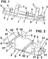
- Figure 1 shows in perspective view a first embodiment of the insert for vehicle wheels according to the present invention.
- the insert according to this embodiment comprises an aesthetic part (1), that can be unpainted, painted, chrome plated or with any other decoration system, and a structural part (2). These components are delivered in a preassembly position according to the picture and cannot be disassembled due to the design of retaining elements (7) and complementary elements (4) provided in the aesthetic part (1), and the structural part (2) respectively.
- Each fixing element (3) to the wheel comprises a protrusion (31) at its distal end with respect to the aesthetical part (1) and oriented outwardly.
- Figure 2 shows in a perspective view the structural part (2), comprising the fixing elements (3), for fixing the structural part to a wheel (not show), and complementary elements (4) to retaining elements (7) included in the aesthetical part (1), shown in figure 3 .
- the complementary elements (4) comprise a wall (41) and a tab (42), and two complementary elements (4) can be connected to each other by bars (43), as shown in figure 2
- the structural part (2) also includes support areas (5) to provide axial contact to the wheel. As shown, these support areas (5) have a big contact surface in order to avoid scratches in the corresponding area of the wheel.
- Figure 3 shows a perspective view of the aesthetical part (1) from the retention area.
- the aesthetical part (1) comprises stiff elements (6) that, in the mounted position, bend and press the fixing elements (3) to the wheel when the aesthetical part (1) moves from the preassembled position to the assembled position.
- Each stiff element (6) can define a U-shaped profile having inclined walls, as shown in figure 3 .
- the combination of the fixing elements (3) working together with stiff elements (6) provides a strong retention to the wheel.
- the retaining elements (7) have two fixing positions with the complementary element (4) of the structural part (2).
- First type of retaining element (7) defines a first portion (71) and a second portion (72), and it comprises a protrusion (73), which engage with the tab (42) of the complementary element (4) in the preassembled position
- the retaining elements (7) can contain also only the first portion (71) or can contain only the second portion (72), the three types of retaining elements (7) can be present in the same aesthetical part (1).
- the first portion (71) is the one that provides the preassembled position with the structural part (2) maintaining a gap with respect to the aesthetical part (1) and assuring both parts (1, 2) could not be disassembled.
- first and second portions (71, 72) are included in the same retaining element (7), the first portion (71) and the second portion (72), are separated by a thickened portion (74) with a thickness greater than the thickness of the rest of the retaining element (7).
- the second portion (72) it is the one that provides the final assembled position between both parts (1, 2) and assures the fixation of the insert to the wheel.
- the tab (42) of the complementary element (4) engages with the transition area between the thickened portion (74) and the second portion (72) of the retaining element (7) and the stiff elements (6) bend and press the complementary fixing elements (3) increasing the engagement with the wheel and increasing the rigidity of fixing elements (3).
- the insert can be removed from the wheel when the aesthetical part (1) is separated from the structural part (2) to the preassembled position. Also, and depending on the shape of the retaining element (7) the aesthetical part (1) can or cannot be separated from the structural part (2). In the case that is specified that the insert should not be removable, the concept design support this requirement having then an antitheft insert
- the structural part (2) comprises holes (9, 10) for the passage of the retaining elements (7) and the stiff elements (6) through the structural part (2) and permitting the engagement with the aesthetical part (1).
- Figures 4 and 5 show perspective views of the insert in the preassembled position. As shown in figure 5 , between the stiff elements (6) and the fixing elements (3) there is a gap or minor interference. Therefore, the pressure to the side wall of the wheel vent pocket during the preassembly process is very low, avoiding scratches.
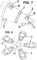
- Figures 6 and 7 show perspective views of the insert in the final assembled position to the wheel.
- the stiff elements (6) have bent the fixing elements (3) outwardly increasing the engagement with the wheel and increasing the rigidity of fixing elements (3) so assuring a strong retention to the wheel.
- the retaining elements (7) and the complementary elements (4) between both parts (1, 2) of the insert are in the final assembled position.
- Figure 8 shows the application of the present invention to a full insert.
- a full star type insert with the aesthetical part (1) preassembled to five structural parts (2), one structural part (2) for every wheel vent pocket. It is shown in assembled position but without the wheel for a better understanding of the concept.
- these aesthetical parts (1) are connected by connecting portions (11).
- the connecting portions can be located in the center as in the example or in any other positions.
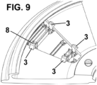
- Figures 9 and 10 show a perspective view of the insert in the preassembled position and in the assembled position, respectively, in the wheel according to a second embodiment, and figure 11 is a cross sectional view through the fixing elements.
- the same numeral references have been used to identify the same or equivalent elements.
- the difference with respect to the first embodiment is that it includes a metal spring (8) between a spring support (81) of the structural part (2) and the stiff elements (6) of the aesthetical part (1).
Abstract
The insert for vehicle wheels comprises a structural part (2) comprising fixing elements (3) configured to fix the structural part to a wheel; and an aesthetical part (1) comprising stiff elements (6) and retaining elements (7) for retaining the aesthetical part (1) to the structural part (2), wherein the aesthetical part (1) and the structural part (2) are movable between a preassembled position and an assembled position, the aesthetical part (1) and the structural part (2) being inseparable to each other in the preassembled position.
It can be easily assembled in the vent pocket from the front side of the wheel and it does not provoke scratches when is assembled or disassembled maintaining the high retention forces required.
Description
- The present invention relates to an insert for vehicle wheels, comprising means for fixing it into a vehicle wheel.
- It is common to use inserts in the wheels of vehicles for aesthetic reasons, wheel weight reduction or aerodynamic improved behavior. Normally these inserts are made of plastic material and are fixed to the wheel rim, which is made of metal.
- The inserts must be fixed to the rim of the vehicle wheel in a reliable way, which prevents the inserts from detaching from the rim for a long time, considering the stresses to which they are subjected due to the speed of rotation of the wheel, wind force, and vibrations.
- Different types of means for fixing these inserts to vehicle rims are currently known.
- A first type of inserts is attached to the wheel rims by means of screws, which must be screwed in from the inside of the wheel. This type of fixing means has the advantage that it is very reliable, since the connection between the insert and the wheel is very durable. However, this type of fixing means has the drawback that it is inconvenient to install, since it requires screwing from the inside of the wheel.
- The methods of fixing the plastic inserts to the wheel by means of screws from the inside of the wheel imply that the assembly of the plastic inserts is carried out by the supplier of the wheel and not on the assembly line of the vehicle manufacturer with the corresponding assembly cost. The vehicle manufacturer is in favor of the front mounting of the plastic inserts in the wheel on their assembly line or by the dealer.
- The fixing system of the plastic inserts by means of screws from the inside of the rim forces the vehicle manufacturer to have more space in its manufacturing plant for the storage of wheels with different references of plastic inserts. This scenario is especially critical when a large number of plastic insert references (different shape or finishes) can be mounted on the same wheel.
- Consequently, the system for fixing the inserts by means of screws from inside the wheel greatly hinders the flexibility desired by the vehicle manufacturer in customizing the vehicle wheel by mounting different plastic inserts on the wheel.
- A second type of inserts are attached to the rims by means of adhesive, for example, a double-sided adhesive tape. This fixation system has been shown in practice to be inadequate since its fixation is permanent and does not allow the insert to be removed and replaced with another.
- A particular case of inserts that are fixed either by screws or by glue are the chrome plated ones. The screws fixation needs to be done as explained above from the rear side of the wheel meanwhile the glue fixation is very expensive and permanent, therefore in the case the insert is damaged needs to substitute the whole wheel.
- It is also known from document
WO 2015/059317 A1 , of the same applicant as the present application, an insert for vehicle wheels comprising fixing means comprising a plurality of projections, each of which is associated with a fixing element that is a protrusion element with a hole of the wheel in the vent pocket area. - A third type of retention is required when the wheel is intended to be used with insert or without insert. In this case is not acceptable to have a protrusion to fix the insert either with a screw or with a system of retention like the one in the document
WO 2015/059317 A1 because of aesthetic reasons. - The insert in this case usually is assembled from the front side and usually uses the vent pockets of the wheel with clips that retain the insert in the back side of the wheel. The clips must be very strong to avoid the insert fly out due to the high rotation of the wheel, wind force or vibrations in the current use of a car. Because of that it can cause scratches in the vent pockets during the assembly or disassembly of the insert, being this one of the major problems of this type of retention.
- In the case the insert is chrome plated the only way to use this type of fixation is using a selective chrome plating process where the whole part is chromed with the exception of the retaining fixtures and the supporting ribs but is difficult to control the unplated area apart from the fact that the cost of this process is huge
- Actual solutions in the market are based on using a material on the area of the clip that contacts the wheel pocket with soft or with lubrication characteristics to reduce or avoid the level of scratches.
- On the other side, these kinds of materials used to be not compatible with the function of the insert or cannot resists the high level of temperatures in the environment of the wheel that mainly come from the breaks. Therefore, the location of these materials used to be restricted to the area of the clip head using complex and expensive production processes.
- Another area where the scratches appear is in the areas of the wheel where the insert lays on. These contact supports are made by ribs that scratches these areas. A possible solution could be the use of wider surfaces instead of ribs, but in this case sink marks would appear in the visible side of the insert in these areas causing unacceptable appearance problems. Also adding in these areas materials with soft or with lubrication characteristics could avoid the scratches but also requires complex and expensive production processes.
- Therefore, there is a clear need for an insert for use in a vehicle wheel that can be easily assembled in the vent pocket from the front side of the wheel and that do not provoke scratches when is assembled or disassembled maintaining the high retention forces required and with wider surfaces in the axial contact areas that do not provoke scratches and at the same time do not cause sink marks in the visible surfaces of the insert.
- With the insert for wheels of the present invention, it is possible to solve the aforementioned drawbacks, presenting other advantages that will be described below.
- The insert for vehicle wheels according to the present invention is described in
claim 1, and dependent claims include additional optional features. - The insert of this invention comprises two parts, an aesthetical part and a structural part, which are preassembled in a delivery condition, in which they cannot be disassembled and have a gap between them.
- The part that is at the back side of the insert when assembled is called structural part, and the part that is in the front side giving the aesthetics of the insert is called aesthetical part.
- The structural part has in the area where the insert lays on the wheel, wider surfaces with round borders that avoids the presence of scratches. There is no risk of visible sink marks because this part is covered by the aesthetical part.
- For the assembly of the insert to the wheel and the engagement of the two parts of the insert to each other, the structural part comprises fixing elements and complementary elements, and the aesthetical part comprises retaining elements and stiff elements.
- The assembly of the insert to the wheel is made from the front side and has two continuous steps. In the first step the fixing elements of the structural part enter in a window of the wheel with a low interference. Because of the low interference and the low stiffness of this fixing means, the pressure of them to the side of wheel windows is very low and due to this fact, do not produce scratches.
- When the insert continues the assembly process to the wheel, starts the second step of the installation. During this process, the stiff elements located in the back side of the aesthetical part start bending a pressing the fixing elements of the structural part up to the assembled position in the wheel and simultaneously the retention between the aesthetical part and the structural part moves from the original preassembly position to the final assembled position.
- That means that both, structural and aesthetical parts, work together increasing dramatically the engagement and the stiffness of the retention and therefore providing a very strong retention to the wheel.
- To remove the insert from the wheel, the process is the opposite; the aesthetical part is moved away from the structural part, until they are in the original preassembled position, such that the fixing elements in this condition make low pressure and the insert assembly is removed from the wheel without damaging the windows of the wheel.
- Depending on the shape of the retaining elements the part can be designed to be not removable.
- This invention is applicable to individual inserts that are assembled in a window of the wheel and to full inserts that covers total or partially the wheel. For example, a full insert assembled to a wheel with five windows will include the aesthetical part of the insert preassembled to five structural parts, one for each window.
- According to a second embodiment, a metal spring is included in the retention area to maintain the pressure between the insert and the wheel, increasing the creep resistance of the system.
- For better understanding of what has been disclosed, some drawings in which, schematically and only by way of a non-limiting example, a practical case of embodiment is shown.
-
Figure 1 is a schematic and perspective view of the insert according to the first embodiment; -
Figure 2 is a schematic and perspective view of the structural part of de insert assembly according to the first embodiment; -
Figure 3 is a schematic and perspective view of the aesthetical part of the insert assembly according to the first embodiment; -
Figure 4 is a schematic and perspective front view of the insert preassembled in the wheel; -
Figure 5 is a schematic and perspective rear view of the insert preassembled in the wheel; -
Figure 6 is a schematic and perspective front view of the insert assembled in the wheel; -
Figure 7 is a schematic and perspective rear view of the insert assembled in the wheel; -
Figure 8 is a schematic and perspective rear view of a full insert in the assembled position; -
Figure 9 is a schematic and perspective rear view of the insert according to the second embodiment preassembled in the wheel; and -
Figure 10 is a schematic and perspective rear view of the insert according to the second embodiment assembled in the wheel; and -
Figure 11 is a schematic cross section of insert according to the second embodiment assembled in the wheel. -
Figure 1 shows in perspective view a first embodiment of the insert for vehicle wheels according to the present invention. - The insert according to this embodiment comprises an aesthetic part (1), that can be unpainted, painted, chrome plated or with any other decoration system, and a structural part (2). These components are delivered in a preassembly position according to the picture and cannot be disassembled due to the design of retaining elements (7) and complementary elements (4) provided in the aesthetic part (1), and the structural part (2) respectively. Each fixing element (3) to the wheel comprises a protrusion (31) at its distal end with respect to the aesthetical part (1) and oriented outwardly.
-
Figure 2 shows in a perspective view the structural part (2), comprising the fixing elements (3), for fixing the structural part to a wheel (not show), and complementary elements (4) to retaining elements (7) included in the aesthetical part (1), shown infigure 3 . The complementary elements (4) comprise a wall (41) and a tab (42), and two complementary elements (4) can be connected to each other by bars (43), as shown infigure 2 - The structural part (2) also includes support areas (5) to provide axial contact to the wheel. As shown, these support areas (5) have a big contact surface in order to avoid scratches in the corresponding area of the wheel.
-
Figure 3 shows a perspective view of the aesthetical part (1) from the retention area. The aesthetical part (1) comprises stiff elements (6) that, in the mounted position, bend and press the fixing elements (3) to the wheel when the aesthetical part (1) moves from the preassembled position to the assembled position. Each stiff element (6) can define a U-shaped profile having inclined walls, as shown infigure 3 . - The combination of the fixing elements (3) working together with stiff elements (6) provides a strong retention to the wheel. The retaining elements (7) have two fixing positions with the complementary element (4) of the structural part (2).
- Can be three types of retaining elements (7). First type of retaining element (7) defines a first portion (71) and a second portion (72), and it comprises a protrusion (73), which engage with the tab (42) of the complementary element (4) in the preassembled position
- The retaining elements (7) can contain also only the first portion (71) or can contain only the second portion (72), the three types of retaining elements (7) can be present in the same aesthetical part (1).
- The first portion (71) is the one that provides the preassembled position with the structural part (2) maintaining a gap with respect to the aesthetical part (1) and assuring both parts (1, 2) could not be disassembled.
- When the first and second portions (71, 72) are included in the same retaining element (7), the first portion (71) and the second portion (72), are separated by a thickened portion (74) with a thickness greater than the thickness of the rest of the retaining element (7). The second portion (72) it is the one that provides the final assembled position between both parts (1, 2) and assures the fixation of the insert to the wheel. In the assembled position the tab (42) of the complementary element (4) engages with the transition area between the thickened portion (74) and the second portion (72) of the retaining element (7) and the stiff elements (6) bend and press the complementary fixing elements (3) increasing the engagement with the wheel and increasing the rigidity of fixing elements (3).
- The insert can be removed from the wheel when the aesthetical part (1) is separated from the structural part (2) to the preassembled position. Also, and depending on the shape of the retaining element (7) the aesthetical part (1) can or cannot be separated from the structural part (2). In the case that is specified that the insert should not be removable, the concept design support this requirement having then an antitheft insert
- As shown in
figure 2 , the structural part (2) comprises holes (9, 10) for the passage of the retaining elements (7) and the stiff elements (6) through the structural part (2) and permitting the engagement with the aesthetical part (1). -
Figures 4 and5 show perspective views of the insert in the preassembled position. As shown infigure 5 , between the stiff elements (6) and the fixing elements (3) there is a gap or minor interference. Therefore, the pressure to the side wall of the wheel vent pocket during the preassembly process is very low, avoiding scratches. - Additionally, it can be seen that the retaining elements (7) and the complementary elements (4) between both parts (1, 2) of the insert are in the preassembly position.
-
Figures 6 and7 show perspective views of the insert in the final assembled position to the wheel. As shown infigure 7 , the stiff elements (6) have bent the fixing elements (3) outwardly increasing the engagement with the wheel and increasing the rigidity of fixing elements (3) so assuring a strong retention to the wheel. Additionally, the retaining elements (7) and the complementary elements (4) between both parts (1, 2) of the insert are in the final assembled position. - When the insert is installed in the wheel, its parts (1, 2) pass from the preassembly to the assembled position in a continuous manner, so the operator only must press the insert until it is fully assembled.
-
Figure 8 shows the application of the present invention to a full insert. In the example is shown a full star type insert with the aesthetical part (1) preassembled to five structural parts (2), one structural part (2) for every wheel vent pocket. It is shown in assembled position but without the wheel for a better understanding of the concept. - As shown in
figure 8 , these aesthetical parts (1) are connected by connecting portions (11). The connecting portions can be located in the center as in the example or in any other positions. -
Figures 9 and10 show a perspective view of the insert in the preassembled position and in the assembled position, respectively, in the wheel according to a second embodiment, andfigure 11 is a cross sectional view through the fixing elements. - For simplicity reasons, the same numeral references have been used to identify the same or equivalent elements. The difference with respect to the first embodiment is that it includes a metal spring (8) between a spring support (81) of the structural part (2) and the stiff elements (6) of the aesthetical part (1).
- Although reference has been made to specific embodiments of the invention, it is apparent to a person skilled in the art that the described insert for vehicle wheels is susceptible of numerous variations and modifications, and that all the details mentioned can be replaced by other technically equivalents, without departing from the scope of protection defined by the appended claims.
Claims (15)
- Insert for vehicle wheels, comprising:a structural part (2) comprising fixing elements (3) configured to fix the structural part to a wheel; andan aesthetical part (1) comprising stiff elements (6) and retaining elements (7) for retaining the aesthetical part (1) to the structural part (2),characterized in that the aesthetical part (1) and the structural part (2) are movable between a preassembled position and an assembled position, the aesthetical part (1) and the structural part (2) being inseparable to each other in the preassembled position.
- Insert for vehicle wheels according to claim 1, wherein when the aesthetical part (1) and the structural part (2) are in the preassembled position, there is a gap between them.
- Insert for vehicle wheels according to claims 1 and 2, wherein when the aesthetical part (1) and the structural part (2) are in the assembled position, the gap between them is reduced with respect to the gap in the preassembled position, and the stiff elements (6) bend and press the complementary fixing elements (3).
- Insert for vehicle wheels according to any one of the previous claims, wherein the structural part (2) comprises support areas (5) to contact the wheel.
- Insert for vehicle wheels according to any one of previous claims, wherein the retaining elements (7) comprises a first portion (71) and/or a second portion (72).
- Insert for vehicle wheels according to claim 5, wherein in the preassembly position, the structural part (2) is retained by the first portion (71) of the retaining elements (7).
- Insert for vehicle wheels according to claim 5 and/or 6, wherein in the assembly position, the structural part (2) is retained by the second portion (72) of the retaining elements (7).
- Insert for vehicle wheels according to claim 5, wherein the first and second portions (71, 72) are included in the same retaining element (7), the first and second portions (71, 72) being separated by a thickened portion (74), having a thickness greater than the rest of the retaining element
- Insert for vehicle wheels according to any one of the previous claims, wherein each fixing element (3) comprises a protrusion (31) oriented outwardly.
- Insert for vehicle wheels according to any one of the previous claims, wherein the structural part (2) comprises complementary elements (4) which are complementary with the retaining elements (7).
- Insert for vehicle wheels according to claim 11, wherein each complementary element (4) comprises a wall (41) and a tab (42).
- Insert for vehicle wheels according to any one of the previous claims, wherein the structural part (2) comprises holes (10) for the passage of the retaining elements (7).
- Insert for vehicle wheels according to any one of the previous claims, wherein the structural part (2) comprises holes (9) for the passage of the stiff elements (6).
- Insert for vehicle wheels according to any one of the previous claims, wherein a spring (8) is placed between each spring support (81) of the structural part (2) and each stiff element (6) of the aesthetical part (1).
- Insert for vehicle wheels according to any one of the previous claims, wherein the insert comprises a plurality of aesthetical parts (1) and a plurality of structural parts (2) wherein the aesthetical parts and/or the structural parts (2) can be connected by connecting portions (11).
Priority Applications (1)
| Application Number | Priority Date | Filing Date | Title |
|---|---|---|---|
| EP22383015.9A EP4357151A1 (en) | 2022-10-21 | 2022-10-21 | Insert for vehicle wheels |
Applications Claiming Priority (1)
| Application Number | Priority Date | Filing Date | Title |
|---|---|---|---|
| EP22383015.9A EP4357151A1 (en) | 2022-10-21 | 2022-10-21 | Insert for vehicle wheels |
Publications (1)
| Publication Number | Publication Date |
|---|---|
| EP4357151A1 true EP4357151A1 (en) | 2024-04-24 |
Family
ID=84331921
Family Applications (1)
| Application Number | Title | Priority Date | Filing Date |
|---|---|---|---|
| EP22383015.9A Pending EP4357151A1 (en) | 2022-10-21 | 2022-10-21 | Insert for vehicle wheels |
Country Status (1)
| Country | Link |
|---|---|
| EP (1) | EP4357151A1 (en) |
Citations (5)
| Publication number | Priority date | Publication date | Assignee | Title |
|---|---|---|---|---|
| JPH0655806U (en) * | 1993-01-13 | 1994-08-02 | 金井 宏之 | Car wheel cap |
| KR20110131930A (en) * | 2010-06-01 | 2011-12-07 | 현대모비스 주식회사 | Easy separating and fixing typed wheel cap |
| WO2015059317A1 (en) | 2013-10-23 | 2015-04-30 | Zanini Auto Grup, S.A. | Cover for vehicle wheels |
| DE202021101794U1 (en) * | 2021-04-02 | 2022-07-15 | Maxion Wheels Holding Gmbh | Vehicle wheel, in particular for commercial vehicles, with an aerodynamic cover and aerodynamic cover for vehicle wheels, in particular for commercial vehicles |
| EP4056382A1 (en) * | 2021-03-11 | 2022-09-14 | Nissan Motor Manufacturing (UK) Limited | Road vehicle wheel assembly |
-
2022
- 2022-10-21 EP EP22383015.9A patent/EP4357151A1/en active Pending
Patent Citations (5)
| Publication number | Priority date | Publication date | Assignee | Title |
|---|---|---|---|---|
| JPH0655806U (en) * | 1993-01-13 | 1994-08-02 | 金井 宏之 | Car wheel cap |
| KR20110131930A (en) * | 2010-06-01 | 2011-12-07 | 현대모비스 주식회사 | Easy separating and fixing typed wheel cap |
| WO2015059317A1 (en) | 2013-10-23 | 2015-04-30 | Zanini Auto Grup, S.A. | Cover for vehicle wheels |
| EP4056382A1 (en) * | 2021-03-11 | 2022-09-14 | Nissan Motor Manufacturing (UK) Limited | Road vehicle wheel assembly |
| DE202021101794U1 (en) * | 2021-04-02 | 2022-07-15 | Maxion Wheels Holding Gmbh | Vehicle wheel, in particular for commercial vehicles, with an aerodynamic cover and aerodynamic cover for vehicle wheels, in particular for commercial vehicles |
Similar Documents
| Publication | Publication Date | Title |
|---|---|---|
| US7828372B2 (en) | Mounting arrangement for mounting cladding to vehicle body | |
| EP1733907B1 (en) | Visor for an automobile | |
| EP1658199B1 (en) | Vehicle body panel with integral clip | |
| EP2097308B1 (en) | Baffle assembly | |
| CA2200927C (en) | Trim panel for a vehicle | |
| US5560669A (en) | Fastenerless retainer assembly | |
| US10737625B2 (en) | Step rail for vehicle with applique and method of making same | |
| JP2001121967A (en) | Vehicle roof module having integral sunroof unit | |
| EP1580078B1 (en) | Metal scuff plate | |
| JP4668948B2 (en) | Method for improving rigidity of vehicle body panel | |
| EP4357151A1 (en) | Insert for vehicle wheels | |
| US4268079A (en) | Shock absorbing bumper | |
| CN209888787U (en) | Trim for a window of a vehicle and trim assembly | |
| EP1736325B1 (en) | Hubcap or wheel cover unit | |
| EP3344497A1 (en) | Exterior applique with interchangeable inserts | |
| CN220720969U (en) | Automobile decoration fixing support | |
| US11773930B2 (en) | Caliper specific decorative brake caliper cover set | |
| CN211032425U (en) | Covering and trim connection structure on vehicle and automobile | |
| CN211166730U (en) | Door chafing strip system, door assembly and car | |
| CN218839358U (en) | Slide rail decoration, slide rail assembly and vehicle | |
| CN114144337B (en) | Trim strip assembly for a motor vehicle door | |
| JP3706930B2 (en) | Automotive bumper cover | |
| EP1270334B1 (en) | Arrangement for fastening the badge on the front side of a motor-vehicle | |
| CN213109253U (en) | Preceding grid and car | |
| CN211893089U (en) | Automobile tail door decoration strip installation structure |
Legal Events
| Date | Code | Title | Description |
|---|---|---|---|
| PUAI | Public reference made under article 153(3) epc to a published international application that has entered the european phase |
Free format text: ORIGINAL CODE: 0009012 |
|
| STAA | Information on the status of an ep patent application or granted ep patent |
Free format text: STATUS: THE APPLICATION HAS BEEN PUBLISHED |
|
| AK | Designated contracting states |
Kind code of ref document: A1 Designated state(s): AL AT BE BG CH CY CZ DE DK EE ES FI FR GB GR HR HU IE IS IT LI LT LU LV MC ME MK MT NL NO PL PT RO RS SE SI SK SM TR |