EP4357058A1 - Structure cutting system, structure cutting method, and cutter system - Google Patents
Structure cutting system, structure cutting method, and cutter system Download PDFInfo
- Publication number
- EP4357058A1 EP4357058A1 EP22824763.1A EP22824763A EP4357058A1 EP 4357058 A1 EP4357058 A1 EP 4357058A1 EP 22824763 A EP22824763 A EP 22824763A EP 4357058 A1 EP4357058 A1 EP 4357058A1
- Authority
- EP
- European Patent Office
- Prior art keywords
- cutter
- structure body
- blade
- cut
- feeder
- Prior art date
- Legal status (The legal status is an assumption and is not a legal conclusion. Google has not performed a legal analysis and makes no representation as to the accuracy of the status listed.)
- Granted
Links
Images




Classifications
-
- B—PERFORMING OPERATIONS; TRANSPORTING
- B23—MACHINE TOOLS; METAL-WORKING NOT OTHERWISE PROVIDED FOR
- B23D—PLANING; SLOTTING; SHEARING; BROACHING; SAWING; FILING; SCRAPING; LIKE OPERATIONS FOR WORKING METAL BY REMOVING MATERIAL, NOT OTHERWISE PROVIDED FOR
- B23D53/00—Machines or devices for sawing with strap saw-blades which are effectively endless in use, e.g. for contour cutting
- B23D53/08—Machines or devices for sawing with strap saw-blades which are effectively endless in use, e.g. for contour cutting for cutting profiled stock
-
- B—PERFORMING OPERATIONS; TRANSPORTING
- B23—MACHINE TOOLS; METAL-WORKING NOT OTHERWISE PROVIDED FOR
- B23D—PLANING; SLOTTING; SHEARING; BROACHING; SAWING; FILING; SCRAPING; LIKE OPERATIONS FOR WORKING METAL BY REMOVING MATERIAL, NOT OTHERWISE PROVIDED FOR
- B23D49/00—Machines or devices for sawing with straight reciprocating saw blades, e.g. hacksaws
- B23D49/001—Machines or devices for sawing with straight reciprocating saw blades, e.g. hacksaws transportable, e.g. fitted with wheels
-
- B—PERFORMING OPERATIONS; TRANSPORTING
- B23—MACHINE TOOLS; METAL-WORKING NOT OTHERWISE PROVIDED FOR
- B23D—PLANING; SLOTTING; SHEARING; BROACHING; SAWING; FILING; SCRAPING; LIKE OPERATIONS FOR WORKING METAL BY REMOVING MATERIAL, NOT OTHERWISE PROVIDED FOR
- B23D49/00—Machines or devices for sawing with straight reciprocating saw blades, e.g. hacksaws
- B23D49/02—Hacksaw machines with straight saw blades secured to a rectilinearly-guided frame, e.g. with the frame fed stepwise in the plane of the guide
-
- B—PERFORMING OPERATIONS; TRANSPORTING
- B23—MACHINE TOOLS; METAL-WORKING NOT OTHERWISE PROVIDED FOR
- B23D—PLANING; SLOTTING; SHEARING; BROACHING; SAWING; FILING; SCRAPING; LIKE OPERATIONS FOR WORKING METAL BY REMOVING MATERIAL, NOT OTHERWISE PROVIDED FOR
- B23D49/00—Machines or devices for sawing with straight reciprocating saw blades, e.g. hacksaws
- B23D49/04—Hacksaw machines with straight saw blades secured to a pivotally-arranged frame
-
- B—PERFORMING OPERATIONS; TRANSPORTING
- B23—MACHINE TOOLS; METAL-WORKING NOT OTHERWISE PROVIDED FOR
- B23D—PLANING; SLOTTING; SHEARING; BROACHING; SAWING; FILING; SCRAPING; LIKE OPERATIONS FOR WORKING METAL BY REMOVING MATERIAL, NOT OTHERWISE PROVIDED FOR
- B23D51/00—Sawing machines or sawing devices working with straight blades, characterised only by constructional features of particular parts; Carrying or attaching means for tools, covered by this subclass, which are connected to a carrier at both ends
- B23D51/04—Sawing machines or sawing devices working with straight blades, characterised only by constructional features of particular parts; Carrying or attaching means for tools, covered by this subclass, which are connected to a carrier at both ends of devices for feeding, positioning, clamping, or rotating work
- B23D51/043—Sawing machines or sawing devices working with straight blades, characterised only by constructional features of particular parts; Carrying or attaching means for tools, covered by this subclass, which are connected to a carrier at both ends of devices for feeding, positioning, clamping, or rotating work for conveying work to, or discharging work from, the machine
-
- B—PERFORMING OPERATIONS; TRANSPORTING
- B23—MACHINE TOOLS; METAL-WORKING NOT OTHERWISE PROVIDED FOR
- B23D—PLANING; SLOTTING; SHEARING; BROACHING; SAWING; FILING; SCRAPING; LIKE OPERATIONS FOR WORKING METAL BY REMOVING MATERIAL, NOT OTHERWISE PROVIDED FOR
- B23D53/00—Machines or devices for sawing with strap saw-blades which are effectively endless in use, e.g. for contour cutting
- B23D53/001—Machines or devices for sawing with strap saw-blades which are effectively endless in use, e.g. for contour cutting transportable, e.g. fitted with wheels
-
- B—PERFORMING OPERATIONS; TRANSPORTING
- B23—MACHINE TOOLS; METAL-WORKING NOT OTHERWISE PROVIDED FOR
- B23D—PLANING; SLOTTING; SHEARING; BROACHING; SAWING; FILING; SCRAPING; LIKE OPERATIONS FOR WORKING METAL BY REMOVING MATERIAL, NOT OTHERWISE PROVIDED FOR
- B23D53/00—Machines or devices for sawing with strap saw-blades which are effectively endless in use, e.g. for contour cutting
- B23D53/04—Machines or devices for sawing with strap saw-blades which are effectively endless in use, e.g. for contour cutting with the wheels carrying the strap mounted shiftably or swingingly, i.e. during sawing, other than merely for adjustment
- B23D53/045—Machines or devices for sawing with strap saw-blades which are effectively endless in use, e.g. for contour cutting with the wheels carrying the strap mounted shiftably or swingingly, i.e. during sawing, other than merely for adjustment with pivotably mounted head carrying the saw wheels
-
- B—PERFORMING OPERATIONS; TRANSPORTING
- B23—MACHINE TOOLS; METAL-WORKING NOT OTHERWISE PROVIDED FOR
- B23D—PLANING; SLOTTING; SHEARING; BROACHING; SAWING; FILING; SCRAPING; LIKE OPERATIONS FOR WORKING METAL BY REMOVING MATERIAL, NOT OTHERWISE PROVIDED FOR
- B23D55/00—Sawing machines or sawing devices working with strap saw blades, characterised only by constructional features of particular parts
-
- B—PERFORMING OPERATIONS; TRANSPORTING
- B23—MACHINE TOOLS; METAL-WORKING NOT OTHERWISE PROVIDED FOR
- B23D—PLANING; SLOTTING; SHEARING; BROACHING; SAWING; FILING; SCRAPING; LIKE OPERATIONS FOR WORKING METAL BY REMOVING MATERIAL, NOT OTHERWISE PROVIDED FOR
- B23D55/00—Sawing machines or sawing devices working with strap saw blades, characterised only by constructional features of particular parts
- B23D55/04—Sawing machines or sawing devices working with strap saw blades, characterised only by constructional features of particular parts of devices for feeding or clamping work
- B23D55/043—Sawing machines or sawing devices working with strap saw blades, characterised only by constructional features of particular parts of devices for feeding or clamping work for conveying work to the sawing machine
-
- F—MECHANICAL ENGINEERING; LIGHTING; HEATING; WEAPONS; BLASTING
- F03—MACHINES OR ENGINES FOR LIQUIDS; WIND, SPRING, OR WEIGHT MOTORS; PRODUCING MECHANICAL POWER OR A REACTIVE PROPULSIVE THRUST, NOT OTHERWISE PROVIDED FOR
- F03D—WIND MOTORS
- F03D13/00—Assembly, mounting or commissioning of wind motors; Arrangements specially adapted for transporting wind motor components
- F03D13/40—Arrangements or methods specially adapted for transporting wind motor components
- F03D13/401—Arrangements or methods specially adapted for transporting wind motor components for transporting or storing blades
Definitions
- the present disclosure relates to a structure body cutting system, a structure body cutting method, and a cutter system.
- Patent Literature 1 discloses a work vehicle equipped with a long processing device.
- Patent Literature 1 Japanese Patent Application Laid-Open Publication No. 5-319164
- a structure body cutting system includes a cutter system mounted on a first moving body moving on a ground or on a sea, and configured to cut a structure body to be cut, and a feeder system mounted on a second moving body moving on the ground or on the sea independently from the first moving body, and configured to send out the structure body to the cutter system.
- the structure body is placed so as to straddle between the cutter system and the feeder system.
- the feeder system sends out the structure body to the cutter system as the second moving body comes close to the first moving body.
- the cutter system cuts the structure body into a plurality of cut segments by cutting the structure body sent out from the feeder system.
- the structure body cutting system of the one aspect of the present disclosure since the cutter system and the feeder system are respectively mounted on the first moving body and the second moving body, it is possible to move the cutter system and the feeder system to arbitrary locations. Therefore, the structure body cutting system can be constructed at a location at which a huge structure body exists. As a result, there is no need to spend a large amount of money to transport the huge structure body for cutting. Further, since the first and second moving bodies can separate the cutter system and the feeder system by a required distance, the huge structure body can be appropriately supported by the cutter system and the feeder system. In addition, since the feeder system can send out the structure body to the cutter system as the second moving body moves, the cutter system can cut the huge structure body. As a result, it is possible to divide the huge structure body into small pieces on the spot.
- a structure body cutting system, a structure body cutting method, and a cutter system according to the present embodiment will be described below with reference to the drawings.
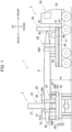
- Figure 1 is a side view schematically showing a configuration of the structure body cutting system according to the present embodiment.
- Figure 2 is a top view schematically showing the configuration of the structure body cutting system according to the present embodiment.
- the three-dimensional directions are defined as the left-right direction, the front-back direction, and the up-down direction.
- the left-right direction and the front-back direction correspond to two directions that are orthogonal in the horizontal direction, and the up-down direction corresponds to the vertical direction.
- these directions are used for convenience only to describe the configuration of the structure body cutting system.
- a structure body cutting system 1 includes a cutter system 2 mounted on a first moving body moving on a ground or on a sea, and configured to cut a structure body to be cut, and a feeder system 5 mounted on a second moving body moving on the ground or on the sea independent from the first moving body, and configured to send out the structure body to the cutter system 2.
- the structure body is placed so as to straddle between the cutter system 2 and the feeder system 5.
- the feeder system 5 sends out the structure body to the cutter system 2 as the second moving body comes close to the first moving body.
- the cutter system 2 cuts the structure body into a plurality of cut segments by cutting the structure body sent out from the feeder system 5.
- the structure body cutting system 1 includes the cutter system 2 that cuts the blade 8 and the feeder system 5 that sends out the blade 8 to the cutter system 2.
- the front-back direction corresponds to a longitudinal direction of the blade 8 and a feeding direction in which the blade 8 is sent out
- the left-right direction corresponds to a lateral direction that intersects with (is orthogonal to in the present embodiment) the feeding direction.
- the cutter system 2 includes a cutter base 30 and a cutter unit 35.
- the cutter system 2 is mounted on a trailer 20 (hereinafter referred to as the "cutting side trailer 20"), which is an example of the first moving body that moves on the ground.
- the cutting side trailer 20 is provided with a loading platform 21 on which an object to be conveyed such as a container is mounted, and a traction vehicle 22 that pulls the loading platform 21.
- a first tightening device 23 that removably fixes the object to be conveyed is provided at each of four corners of the loading platform 21, a first tightening device 23 that removably fixes the object to be conveyed is provided.
- the first tightening device 23 is, for example, a twist lock.
- the cutter base 30 is a plate-shaped base member on which the cutter unit 35 is mounted.
- the cutter unit 35 is fixed to the cutter base 30 by a fastening means such as a bolt.
- the cutter base 30 has the same shape and size as the loading platform 21 of the cutting side trailer 20, but is not limited to this.
- a first fixed portion 31 to which the first tightening device 23 is fixed is provided on a lower surface side of the cutter base 30 so as to correspond to the first tightening device 23 on a side of the loading platform 21.
- the first fixed portion 31 is configured with an elongated hole or the like that is suitable for the first tightening device 23 to be inserted.
- the cutter base 30 is removably fixed to the cutting side trailer 20 via the first tightening device 23 of the loading platform 21.
- the cutter unit 35 is provided with various elements for cutting the blade 8. Specifically, the cutter unit 35 includes a first support mechanism 36, a cutter 37, a second support mechanism 38, an alignment member 39, a first width aligning mechanism 40, a second width aligning mechanism 41, and an operation panel 42.
- the first support mechanism 36 is provided on a front side of the cutter 37, that is, on a loading side on which the blade 8 is loaded with respect to the cutter 37.
- the first support mechanism 36 supports the blade 8 that is sent out from the feeder system 5 to the cutter 37.
- the first support mechanism 36 supports the blade 8 such that a feeding height (a pass line) for feeding the blade 8 is a predetermined reference height Ha.
- the first support mechanism 36 is configured with a first rotating roller 360 that rotates around a rotation axis extending in the left-right direction, and support legs 361 and 362 that rotatably support the first rotating roller 360.
- FIGS 3 and 4 are explanatory diagrams schematically showing a configuration of the cutter 37.
- the cutter 37 cuts the blade 8 that is supported by the first support mechanism 36.
- the cutter 37 is configured with a horizontal band saw machine.
- the cutter 37 is mainly configured with a saw blade housing 370 and a hinge mechanism 375.
- the saw blade housing 370 includes a driving wheel 371, a driven wheel 372, and a band saw blade 373 tightly stretched between the driving wheel 371 and the driven wheel 372.
- the driving wheel 371 and the driven wheel 372 are rotatably attached to the saw blade housing 370. Power from a drive mechanism including a motor, a gear, and the like is transmitted to the driving wheel 371 and the driving wheel 371 is rotationally driven as the power is received.
- the band saw blade 373 travels by a rotational drive of the driving wheel 371.
- the hinge mechanism 375 includes a hinge shaft 376 provided parallel to a rotation axis of the driving wheel 371.
- the saw blade housing 370 is fixed to the cutter base 30 via the hinge mechanism 375 and is configured to be rotatable around the hinge shaft 376.
- the saw blade housing 370 can be rotated between an upper limit position (see Figure 3 ) at which a travel line of the band saw blade 373 is substantially in the vertical direction and a lower limit position (see Figure 4 ) at which the travel line of the band saw blade 373 is substantially in the horizontal direction.
- the travel line of the band saw blade 373 when the saw blade housing 370 is at the lower limit position is set to be below a height of the blade 8 that is supported by the first support mechanism 36, that is, the reference height Ha.
- the second support mechanism 38 is provided at a position opposed to the first support mechanism 36 with the cutter 37 interposed therebetween.
- the second support mechanism 38 is provided on a rear side of the cutter 37, that is, on an unloading side on which the blade 8 (the cut segment) cut by the cutter 37 is unloaded.
- the second support mechanism 38 supports the blade 8 that is cut by the cutter 37.
- the second support mechanism 38 includes a pair of support bodies 380 and 381 configured to be movable up and down in the up-down direction.
- the pair of support bodies 380 and 381 are arranged so as to be separated by a certain distance in the front-back direction.
- the blade 8 cut by the cutter 37 is supported at two points by the pair of support bodies 380 and 381.
- Each of the support bodies 380 and 381 includes a drive mechanism such as a hydraulic cylinder, and receives power from the drive mechanism to move up and down independently in the up-down direction.
- each of the support bodies 380 and 381 can support the blade 8 at the same height as the reference height Ha at which the first support mechanism 36 supports the blade 8, or at a height different from the reference height Hb.
- the alignment member 39 aligns a position of the blade 8 with respect to the cutter 37 as an end surface 8a of the blade 8 extending along the front-back direction is brought into contact with the alignment member 39.
- the alignment member 39 is configured with a second rotating roller 390 that rotates around a rotating axis extending in the up-down direction, and a pedestal portion (not shown) that rotatably supports the second rotating roller 390.
- the alignment member 39 is provided between the first support mechanism 36 and the cutter 37.
- the first width aligning mechanism 40 is provided at a position opposed to the alignment member 39 in the left-right direction.
- the first width aligning mechanism 40 includes a first movable member 400 configured to be movable in the left-right direction, and a drive mechanism (not shown) such as a hydraulic cylinder that moves the first movable member 400 in the left-right direction.
- the first width aligning mechanism 40 fixes the blade 8 between itself and the alignment member 39 by moving the first movable member 400 in the right direction.
- the first width aligning mechanism 40 releases the fixation of the blade 8 by moving the first movable member 400 in the left direction.
- the first movable member 400 can move in the left direction up to a predetermined fully open position.
- the second width aligning mechanism 41 is mounted on the support body 380 on a front side in the second support mechanism 38.
- the second width aligning mechanism 41 includes a pair of second movable members 410 and 411 that are provided at positions opposed to each other in the left-right direction, and a drive mechanism (not shown) such as a hydraulic cylinder.
- the pair of second movable members 410 and 411 are configured to be movable in the left-right direction, and each of the pair of second movable members 410 and 411 moves along the left-right direction by receiving power from the drive mechanism.
- the second width aligning mechanism 41 fixes the blade 8 between the pair of second movable members 410 and 411 by moving the pair of second movable members 410 and 411 along the left-right direction so as to be close with each other. Further, the second width aligning mechanism 41 releases the fixation of the blade 8 by moving the pair of second movable members 410 and 411 along the left-right direction so as to be away from each other. Each of the pair of second movable members 410 and 411 can move in the left-right direction up to a predetermined fully open position.
- the operation panel 42 is a device for controlling the operations of the cutter 37, the second support mechanism 38, the first width aligning mechanism 40, and the second width aligning mechanism 41.
- the operation panel 42 is operated by an operator who uses the structure body cutting system 1, for example.
- the feeder system 5 includes a feeder base 60 and a feeder unit 65.
- the feeder system 5 is mounted on a trailer 50 (hereinafter referred to as the "feeding side trailer 50"), which is an example of the second moving body that moves on the ground.
- the feeding side trailer 50 includes a loading platform 51 on which the object to be conveyed such as the container is mounted, and a traction vehicle 52 that pulls the loading platform 51.
- a second tightening device 53 that removably fixes the object to be conveyed is provided at each of four corners of the loading platform 51.
- the second tightening device 53 is, for example, the twist lock.
- the feeder base 60 is a plate-shaped base member on which the feeder unit 65 is mounted.
- the feeder unit 65 is fixed to the cutter base 30 by the fastening means such as the bolt.
- the feeder base 60 has the same shape and size as the loading platform 51 of the feeding side trailer 50, but is not limited to this.
- a second fixed portion 61 to which the second tightening device 53 is fixed is provided on a lower surface side of the feeder base 60 so as to correspond to the second tightening device 53 on a side of the loading platform 51.
- the second fixed portion 61 is configured with the elongated hole or the like that is suitable for the second tightening device 53 to be inserted.
- the feeder base 60 is removably fixed to the feeding side trailer 50 via the second tightening device 53 of the loading platform 51.
- the feeder unit 65 is provided with various elements for sending out the blade 8 to the cutter system 2. Specifically, the feeder unit 65 includes a third support mechanism 66, an abutment unit 67, a third width aligning mechanism 68, and an operation panel 69.
- the third support mechanism 66 supports the blade 8 that is sent out to the cutter system 2.
- the third support mechanism 66 supports the blade 8 such that the feeding height (the pass line) for feeding the blade 8 is the predetermined reference height Ha.
- the abutment unit 67 is a vertical wall-shaped member that stands up in the vertical direction. As the cutter system 2 moves backward, a blade edge 8b of the blade 8 in the front-back direction abuts against the abutment unit 67, which makes it possible to push the blade 8 toward a side of the cutter system 2.
- the third width aligning mechanism 68 is provided between the abutment unit 67 and the third support mechanism 66.
- the third width aligning mechanism 68 includes a pair of third movable members 680 and 681 that are provided at positions opposed to each other in the left-right direction, and a drive mechanism (not shown) such as a hydraulic cylinder.
- the pair of third movable members 680 and 681 are configured to be movable in the left-right direction, and each of the pair of third movable members 680 and 681 moves along the left-right direction by receiving power from the drive mechanism.
- the third width aligning mechanism 68 fixes the blade 8 between the pair of third movable members 680 and 681 by moving the pair of third movable members 680 and 681 along the left-right direction so as to be close with each other. Further, the third width aligning mechanism 68 releases the fixation of the blade 8 by moving the pair of third movable members 680 and 681 along the left-right direction so as to be away from each other. Each of the pair of third movable members 680 and 681 can move in the left-right direction up to a predetermined fully open position.
- the operation panel 69 is a device for operating the operation of the third width aligning mechanism 68.
- the operation panel 42 is operated by the operator who uses the structure body cutting system 1, for example.
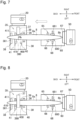
- FIGs 5 to 10 are diagrams for explaining the structure body cutting method according to the present embodiment.
- the structure body cutting method according to the present embodiment that is, a method of cutting the blade 8 by the structure body cutting system 1 will be described below. It should be noted that in Figures 5 to 10 , the description of the operation panels 42 and 69 are omitted for convenience of explanation.
- the feeding side trailer 50 is positioned with respect to the cutting side trailer 20. With this positioning, each of the trailers 20 and 50 is arranged such that a straight travel direction (a forward travel direction and a backward travel direction) of the cutting side trailer 20 intersects with a straight travel direction of the feeding side trailer 50, and the cutting side trailer 20 is on an extension of a backward travel direction of the feeding side trailer 50.
- the cutting side trailer 20 is arranged rightward in the left-right direction
- the feeding side trailer 50 is arranged forward in the front-back direction.
- the two trailers 20 and 50 are lined up on a straight line parallel to the front-back direction such that their straight travel directions are orthogonal to each other.
- the operator After the two trailers 20 and 50 are positioned, the operator operates the operation panels 42 and 69 to move the first movable member 400 of the first width aligning mechanism 40, the pair of second movable members 410 and 411 of the second width aligning mechanism 41, and the pair of third movable members 680 and 681 of the third width aligning mechanism 68 to the fully open positions.
- the operator operates the operation panel 42 to lower the pair of support bodies 380 and 381 of the second support mechanism 38 to the lowest position.
- the blade 8 to be cut is brought in from above by using an external crane or the like, and placed so as to straddle between the cutter system 2 and the feeder system 5.
- the blade 8 is supported by each of the first support mechanism 36 of the cutter system 2 and the third support mechanism 66 of the feeder system 5.
- the blade 8 is placed in a state in which the longitudinal direction of the blade 8 coincides with the front-back direction.
- the blade edge 8b of the blade 8 on the side of the feeder system 5 is in a state of being abutted against the abutment unit 67.
- the end surface 8a of the blade 8 along the front-back direction is in a state of being in contact with the alignment member 39.
- the operator When the blade 8 is placed, the operator operates the operation panel 69 to perform a width aligning operation by the third width aligning mechanism 68.
- the width aligning operation the pair of third movable members 680 and 681 move along the left-right direction so as to be close with each other.
- the blade 8 is fixed between the pair of third movable members 680 and 681.
- the feeder system 5 sends out the blade 8 to the cutter system 2 along the longitudinal direction of the blade 8.
- the feeding side trailer 50 is moved back by a predetermined movement amount so that a cut position Pb of the blade 8 reaches the cutter 37 of the feeder system 5.
- the cut position Pb of the blade 8 is determined in consideration of a center of gravity of the cut segment, which is a part cut out from the blade 8, and a length of the cut segment. Specifically, the cut position Pb of the blade 8 is determined such that the center of gravity of the cut segment is positioned between the pair of support bodies 380 and 381 of the second support mechanism 38 and the length of the cut segment is a length transportable by land.
- the feeding side trailer 50 is moved backward while the backward direction of the feeding side trailer 50 is being adjusted so as to maintain the state in which the end surface 8a of the blade 8 is in contact with the alignment member 39.
- the blade 8 can be sent out so as to stay within a cutting region of the cutter 37.
- the cutting region of the cutter 37 is a region in which the band saw blade 373 cuts the blade 8, and corresponds to a region between the driving wheel 371 and the driven wheel 372 in the band saw blade 373.
- the operator operates the operation panel 42 to perform a width aligning mechanism on the side of the cutter system 2, that is, a width aligning operation by the first width aligning mechanism 40 and the second width aligning mechanism 41.
- a width aligning operation by the first width aligning mechanism 40 and the second width aligning mechanism 41.
- the first movable member 400 moves in the right direction, and the pair of second movable members 410 and 411 move along the left and right direction so as to be close with each other.
- the blade 8 is fixed between the alignment member 39 and the first movable member 400, and fixed between the pair of third movable members 680 and 681.
- the operator operates the operation panel 42 to move up the pair of support bodies 380 and 381 of the second support mechanism 38 until they abut against the blade 8.
- the operator operates the operation panel 42 to rotate the saw blade housing 370 up to the lower limit position while causing the band saw blade 373 of the cutter 37 to travel, and then returns the saw blade housing 370 to the upper limit position.
- the blade 8 is cut (divided) by the cutter 37.
- the cut segment which is a part cut out by the cutter 37 from the blade 8, is supported by the pair of support bodies 380 and 381 of the second support mechanism 38.
- the operator operates the operation panels 42 and 69 to move the first width aligning mechanism 40 and the second width aligning mechanism 41 to the fully open positions.
- the cut segment is removed from the second support mechanism 38 by the crane or the like. Then, by repeating the above-described operation for a new cut position Pb1 on the remaining blade 8, the blade 8 is divided into the plurality of the cut segments. It should be noted that since there are a plurality of the blades 8 of the wind power generation device, it is possible to store the operations of the operator and automatically reuse them. Further, if the shape of the blade is set in advance, it is possible to automate the operation including the operation of the feeding side trailer 50.
- the structure body cutting system 1 of the present embodiment includes the cutter system 2 mounted on the cutting side trailer 20, and the feeder system 5 mounted on the feeding side trailer 50.
- the blade 8 is placed so as to straddle between the cutter system 2 and the feeder system 5.
- the feeder system 5 sends out the blade 8 to the cutter system 2 as the feeding side trailer 50 comes close to the cutting side trailer 20.
- the cutter system 2 cuts the blade 8 into the plurality of the cut segments by cutting the blade 8 sent out from the feeder system 5.
- the cutter system 2 and the feeder system 5 are respectively mounted on the cutting side trailer 20 and the feeding side trailer 50, it is possible to move the cutter system 2 and the feeder system 5 to arbitrary locations. Since the structure body cutting system 1 can be constructed at a location at which the blade 8, which is a huge structure body, is present, there is no need to spend a huge amount of money to transport the huge blade 8. Further, since the cutter system 2 and the feeder system 5 can be separated by the cutting side trailer 20 and the feeding side trailer 50 by a required distance, it is possible to support both sides of the blade 8 in accordance with a length of the huge blade 8. In addition, since the feeder system 5 can send out the blade 8 to the cutter system 2 as the feeding side trailer 50 moves, the cutter system 2 can cut the huge structure body. As a result, it is possible to cut the huge blade 8 into small pieces on the spot.
- a system suitable for cutting the huge blade 8 can be provided.
- the cutter system 2 includes a first support mechanism 36 that supports the blade 8 sent out along the longitudinal direction, the cutter 37 that cuts the blade 8 supported by the first support mechanism 36, the second support mechanism 38 that is provided to be movable up and down in the up-down direction at the position opposed to the first support mechanism 36 with the cutter 37 interposed therebetween, and is configured to support the cut segment (a part cut out from the blade 8) that is cut by the cutter 37, and the alignment member 39 that aligns the position of the blade 8 with respect to the cutter 37 as the end surface 8a of the blade 8 is brought into contact with the alignment member 39.
- the first support mechanism 36 and the second support mechanism 38 are arranged with the cutter 37 interposed therebetween. Therefore, the first support mechanism 36 can support the blade 8 on the loading side with respect to the cutter 37 and the second support mechanism 38 can support the blade 8 on the unloading side with respect to the cutter 37. As a result, the blade 8 can be appropriately cut by the cutter 37.
- the pass line (the reference height Ha), which is the feeding height at which a workpiece is fed, has a constant height from the loading side to the unloading side.
- the cutter system 2 and the feeder system 5 are independent and arranged at the arbitrary locations, the cutter system 2 and the feeder system 5 are not always arranged in a same height environment due to an inclination of the land or an undulation of the land.
- the blade 8 which is the object to be cut, has a twisted shape along the longitudinal direction, the blade 8 is also not in a shape along the pass line.
- Figure 11 is a diagram showing a relationship between the cutter system and the feeder system.
- the second support mechanism 38 provided on the unloading side with respect to the cutter 37 is configured to be movable up and down in the up-down direction. Even if the pass line of the cutter system 2 and the pass line of the feeder system 5 are different from each other, or the blade 8 having the twisted shape is to be fed, it is possible to cause the second support mechanism 38 to appropriately follow the blade 8. By having the second support mechanism 38, it is possible to ensure effectiveness of the cutting for the blade 8 regardless of the difference in the pass line and the shape of the blade 8.
- the cutter system 2 includes the alignment member 39 that aligns the position of the blade 8 with respect to the cutter 37.
- the alignment member 39 that aligns the position of the blade 8 with respect to the cutter 37.
- the feeding side trailer 50 is moved back so that the state in which the end surface 8a of the blade 8 is in contact with the alignment member 39 is maintained in order for the blade 8 sent out to the cutter 37 to stay within the cutting region of the cutter 37.
- the positioning of the blade 8 with respect to the cutter 37 is not limited to this method.
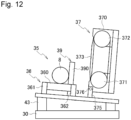
- FIG 12 is an explanatory diagram showing a modified example of the cutter system.
- the cutter system 2 may include a tilting mechanism 43 that tilts the cutter unit, and the tilting mechanism 43 may tilt the cutter unit 35 such that the first support mechanism 36 is inclined downward toward the alignment member 39.
- the tilting mechanism 43 may be configured to tilt only the first support mechanism 36, other than to tilt the entire cutter unit 35.
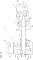
- FIG 13 is an explanatory diagram showing a modified example of the cutter system.
- the feeder system 5 may include a rotation mechanism 62 on the feeder base 60 so as to rotate the feeder unit 65 around a rotation axis along the up-down direction.
- This rotation mechanism 62 allows the longitudinal direction of the blade 8 to be offset with respect to the backward travel direction of the feeding side trailer 50. As a result, by shifting the longitudinal direction of the blade 8 with respect to the backward travel direction of the feeding side trailer 50, it is possible to maintain the state in which the blade 8 is in contact with the alignment member 39.
- the cutter system 2 further includes the first width aligning mechanism 40 and the second width aligning mechanism 41.
- the first width aligning mechanism 40 fixes the blade 8 between the alignment member 39 and the first movable member 400 as the first movable member 400, which is provided at the position opposed to the alignment member 39 in the lateral direction that intersects with the feeding direction, moves along the lateral direction.
- the second width aligning mechanism 41 fixes the blade 8 between the pair of second movable members 410 and 411 as the pair of second movable members 410 and 411, which are provided at the positions opposed to each other in the lateral direction, move along the lateral direction so as to be close with each other.
- the blade 8 has the twisted shape, and simply supporting a lower side of the blade 8 may not stabilize the blade 8 when being cut by the cutter 37.
- the blade 8 can be fixed from the left-right direction so that the cutting by the cutter 37 can be stably performed.
- the cutter base 30 which is a base member on which the elements constituting the cutter system 2 are mounted, is configured to be mountable to and removable from the cutting side trailer 20. Then, the cutter base 30 includes the first fixed portion 31 to which the first tightening device 23 installed on the loading platform 21 is fixed.
- the cutter 37 is a band saw machine in which the saw blade housing 370 including the band saw blade 373 is configured to be rotatable in the up-down direction around the hinge shaft 376 provided parallel to the rotation axis of the driving wheel 371.
- interference between the blade 8 and the saw blade housing 370 can be suppressed by rotating the saw blade housing 370 to the upper limit position when the blade 8 is placed by the crane.
- the blade 8 can be easily placed only by up-down movement of the crane.
- the feeder system 5 includes the third support mechanism 66 configured to support the blade 8, the abutment unit 67 against which the blade edge 8b of the blade 8 in the feeding direction abuts, and the third width aligning mechanism 68 configured to fix the blade 8 between the pair of third movable members 680 and 681 as the pair of third movable members 680 and 681 provided at the positions opposed to each other move in the lateral direction so as to be close with each other in the lateral direction.
- the blade 8 placed so as to straddle between the cutter system 2 and the feeder system 5 can be appropriately sent out to the cutter system 2.
- the cutter system 2 can cut the blade 8 into the plurality of the cut segments.
- the structure body cutting method described in the present embodiment has an idea common to the cutting operation of the blade 8 by the structure body cutting system 1 described above, and has the same effect as the structure body cutting system 1.
- the cutter 37 configured with the band saw machine is exemplified.
- the cutter 37 may also be a saw cutter such as a hacksaw machine that performs cutting with a hacksaw blade.
- the cutter 37 may be a laser cutter that performs laser cutting.
- a saw blade housing including a linear hacksaw blade that reciprocates along the longitudinal direction is configured to be rotational in the up-down direction around a hinge shaft provided parallel to the direction orthogonal to the longitudinal direction of the hacksaw blade.
- the cutter system 2 and the feeder system 5 are mounted on the trailers, but they may be mounted on vehicles that move on the ground other than the trailers. Further, the cutter system 2 and the feeder system 5 may be mounted on ships moving on the sea. The cutter system 2 and the feeder system 5 may be ships.
- the blade 8 is shown as the structure body to be cut by the structure body cutting system 1.
- the structure body may also be a support column that supports a rotary wing consisting of a plurality of the blades in the wind power generation device, or a huge structure body other than that.
Landscapes
- Engineering & Computer Science (AREA)
- Mechanical Engineering (AREA)
- Sawing (AREA)
- Shearing Machines (AREA)
Abstract
Description
- The present disclosure relates to a structure body cutting system, a structure body cutting method, and a cutter system.
- In recent years, attention has been focused on a wind power generation device with reduced environmental burden. The wind power generation device that has passed its useful life is disassembled, and parts of the wind power generation device such as a blade are discarded. Since the blade and the like are huge structure bodies, they cannot be easily transported, resulting in a great cost. Therefore, it is desired that the huge structure body represented by the blade of the wind power generation device and the like be divided into small pieces before being transported.
- For example, Patent Literature 1 discloses a work vehicle equipped with a long processing device.
- Patent Literature 1:
Japanese Patent Application Laid-Open Publication No. 5-319164 - However, conventionally, no machine has been suitable for dividing the huge structure body. Needless to say, it is also possible to cut the structure body with a hand tool, but it requires a tremendous number of man-hours. In other words, a cutting system suitable for dividing the large structure body is desired.
- A structure body cutting system according to one aspect of the present disclosure includes a cutter system mounted on a first moving body moving on a ground or on a sea, and configured to cut a structure body to be cut, and a feeder system mounted on a second moving body moving on the ground or on the sea independently from the first moving body, and configured to send out the structure body to the cutter system. The structure body is placed so as to straddle between the cutter system and the feeder system. The feeder system sends out the structure body to the cutter system as the second moving body comes close to the first moving body. The cutter system cuts the structure body into a plurality of cut segments by cutting the structure body sent out from the feeder system.
- According to the structure body cutting system of the one aspect of the present disclosure, since the cutter system and the feeder system are respectively mounted on the first moving body and the second moving body, it is possible to move the cutter system and the feeder system to arbitrary locations. Therefore, the structure body cutting system can be constructed at a location at which a huge structure body exists. As a result, there is no need to spend a large amount of money to transport the huge structure body for cutting. Further, since the first and second moving bodies can separate the cutter system and the feeder system by a required distance, the huge structure body can be appropriately supported by the cutter system and the feeder system. In addition, since the feeder system can send out the structure body to the cutter system as the second moving body moves, the cutter system can cut the huge structure body. As a result, it is possible to divide the huge structure body into small pieces on the spot.
- According to the one aspect of the present disclosure, it is possible to provide the cutting system suitable for dividing the huge structure body.
-
- [
Figure 1] Figure 1 is a side view schematically showing a configuration of a structure body cutting system according to the present embodiment. - [
Figure 2] Figure 2 is a top view schematically showing the configuration of the structure body cutting system according to the present embodiment. - [
Figure 3] Figure 3 is an explanatory diagram showing the configuration of a cutter of a cutter system. - [
Figure 4] Figure 4 is an explanatory diagram showing the configuration of the cutter of the cutter system. - [
Figure 5] Figure 5 is a diagram for explaining a structure body cutting method according to the present embodiment. - [
Figure 6] Figure 6 is a diagram for explaining the structure body cutting method according to the present embodiment. - [
Figure 7] Figure 7 is a diagram for explaining the structure body cutting method according to the present embodiment. - [
Figure 8] Figure 8 is a diagram for explaining the structure body cutting method according to the present embodiment. - [
Figure 9] Figure 9 is a diagram for explaining the structure body cutting method according to the present embodiment. - [
Figure 10] Figure 10 is a diagram for explaining the structure body cutting method according to the present embodiment. - [
Figure 11] Figure 11 is a diagram showing a relationship between the cutter system and the feeder system. - [
Figure 12] Figure 12 is an explanatory diagram showing a modified example of the cutter system. - [
Figure 13] Figure 13 is an explanatory diagram showing a modified example of the feeder system. - A structure body cutting system, a structure body cutting method, and a cutter system according to the present embodiment will be described below with reference to the drawings.
-
Figure 1 is a side view schematically showing a configuration of the structure body cutting system according to the present embodiment.Figure 2 is a top view schematically showing the configuration of the structure body cutting system according to the present embodiment. In the following description, the three-dimensional directions are defined as the left-right direction, the front-back direction, and the up-down direction. The left-right direction and the front-back direction correspond to two directions that are orthogonal in the horizontal direction, and the up-down direction corresponds to the vertical direction. However, these directions are used for convenience only to describe the configuration of the structure body cutting system. - A structure body cutting system 1 according to the present embodiment includes a
cutter system 2 mounted on a first moving body moving on a ground or on a sea, and configured to cut a structure body to be cut, and afeeder system 5 mounted on a second moving body moving on the ground or on the sea independent from the first moving body, and configured to send out the structure body to thecutter system 2. The structure body is placed so as to straddle between thecutter system 2 and thefeeder system 5. Thefeeder system 5 sends out the structure body to thecutter system 2 as the second moving body comes close to the first moving body. Thecutter system 2 cuts the structure body into a plurality of cut segments by cutting the structure body sent out from thefeeder system 5. - The configuration of the structure body cutting system 1 will be described in detail below. In the following description, a
blade 8 of a wind power generation device is exemplified as the structure body to be cut. Theblade 8 has a longitudinal shape extending in one direction while being twisted. As shown inFigures 1 and2 , the structure body cutting system 1 includes thecutter system 2 that cuts theblade 8 and thefeeder system 5 that sends out theblade 8 to thecutter system 2. In the example shown inFigures 1 and2 , the front-back direction corresponds to a longitudinal direction of theblade 8 and a feeding direction in which theblade 8 is sent out, and the left-right direction corresponds to a lateral direction that intersects with (is orthogonal to in the present embodiment) the feeding direction. - The
cutter system 2 includes acutter base 30 and acutter unit 35. Thecutter system 2 is mounted on a trailer 20 (hereinafter referred to as the "cutting side trailer 20"), which is an example of the first moving body that moves on the ground. Thecutting side trailer 20 is provided with aloading platform 21 on which an object to be conveyed such as a container is mounted, and atraction vehicle 22 that pulls theloading platform 21. At each of four corners of theloading platform 21, afirst tightening device 23 that removably fixes the object to be conveyed is provided. Thefirst tightening device 23 is, for example, a twist lock. - The
cutter base 30 is a plate-shaped base member on which thecutter unit 35 is mounted. Thecutter unit 35 is fixed to thecutter base 30 by a fastening means such as a bolt. - The
cutter base 30 has the same shape and size as theloading platform 21 of thecutting side trailer 20, but is not limited to this. A first fixedportion 31 to which thefirst tightening device 23 is fixed is provided on a lower surface side of thecutter base 30 so as to correspond to thefirst tightening device 23 on a side of theloading platform 21. The first fixedportion 31 is configured with an elongated hole or the like that is suitable for thefirst tightening device 23 to be inserted. Thecutter base 30 is removably fixed to the cuttingside trailer 20 via thefirst tightening device 23 of theloading platform 21. - The
cutter unit 35 is provided with various elements for cutting theblade 8. Specifically, thecutter unit 35 includes afirst support mechanism 36, acutter 37, asecond support mechanism 38, analignment member 39, a firstwidth aligning mechanism 40, a secondwidth aligning mechanism 41, and anoperation panel 42. - The
first support mechanism 36 is provided on a front side of thecutter 37, that is, on a loading side on which theblade 8 is loaded with respect to thecutter 37. Thefirst support mechanism 36 supports theblade 8 that is sent out from thefeeder system 5 to thecutter 37. Thefirst support mechanism 36 supports theblade 8 such that a feeding height (a pass line) for feeding theblade 8 is a predetermined reference height Ha. For example, thefirst support mechanism 36 is configured with a firstrotating roller 360 that rotates around a rotation axis extending in the left-right direction, and supportlegs rotating roller 360. -
Figures 3 and 4 are explanatory diagrams schematically showing a configuration of thecutter 37. Thecutter 37 cuts theblade 8 that is supported by thefirst support mechanism 36. In the example shown inFigures 3 and 4 , thecutter 37 is configured with a horizontal band saw machine. Thecutter 37 is mainly configured with asaw blade housing 370 and ahinge mechanism 375. - The
saw blade housing 370 includes adriving wheel 371, a drivenwheel 372, and aband saw blade 373 tightly stretched between thedriving wheel 371 and the drivenwheel 372. Thedriving wheel 371 and the drivenwheel 372 are rotatably attached to thesaw blade housing 370. Power from a drive mechanism including a motor, a gear, and the like is transmitted to thedriving wheel 371 and thedriving wheel 371 is rotationally driven as the power is received. The band sawblade 373 travels by a rotational drive of thedriving wheel 371. - The
hinge mechanism 375 includes ahinge shaft 376 provided parallel to a rotation axis of thedriving wheel 371. Thesaw blade housing 370 is fixed to thecutter base 30 via thehinge mechanism 375 and is configured to be rotatable around thehinge shaft 376. Thesaw blade housing 370 can be rotated between an upper limit position (seeFigure 3 ) at which a travel line of theband saw blade 373 is substantially in the vertical direction and a lower limit position (seeFigure 4 ) at which the travel line of theband saw blade 373 is substantially in the horizontal direction. The travel line of theband saw blade 373 when thesaw blade housing 370 is at the lower limit position is set to be below a height of theblade 8 that is supported by thefirst support mechanism 36, that is, the reference height Ha. - Referring again to
Figures 1 and2 , thesecond support mechanism 38 is provided at a position opposed to thefirst support mechanism 36 with thecutter 37 interposed therebetween. In other words, thesecond support mechanism 38 is provided on a rear side of thecutter 37, that is, on an unloading side on which the blade 8 (the cut segment) cut by thecutter 37 is unloaded. Thesecond support mechanism 38 supports theblade 8 that is cut by thecutter 37. - For example, the
second support mechanism 38 includes a pair ofsupport bodies support bodies blade 8 cut by thecutter 37 is supported at two points by the pair ofsupport bodies support bodies support bodies blade 8 at the same height as the reference height Ha at which thefirst support mechanism 36 supports theblade 8, or at a height different from the reference height Hb. - The
alignment member 39 aligns a position of theblade 8 with respect to thecutter 37 as anend surface 8a of theblade 8 extending along the front-back direction is brought into contact with thealignment member 39. For example, thealignment member 39 is configured with a secondrotating roller 390 that rotates around a rotating axis extending in the up-down direction, and a pedestal portion (not shown) that rotatably supports the secondrotating roller 390. In the example shown inFigure 1 , thealignment member 39 is provided between thefirst support mechanism 36 and thecutter 37. - The first
width aligning mechanism 40 is provided at a position opposed to thealignment member 39 in the left-right direction. The firstwidth aligning mechanism 40 includes a firstmovable member 400 configured to be movable in the left-right direction, and a drive mechanism (not shown) such as a hydraulic cylinder that moves the firstmovable member 400 in the left-right direction. The firstwidth aligning mechanism 40 fixes theblade 8 between itself and thealignment member 39 by moving the firstmovable member 400 in the right direction. The firstwidth aligning mechanism 40 releases the fixation of theblade 8 by moving the firstmovable member 400 in the left direction. The firstmovable member 400 can move in the left direction up to a predetermined fully open position. - The second
width aligning mechanism 41 is mounted on thesupport body 380 on a front side in thesecond support mechanism 38. The secondwidth aligning mechanism 41 includes a pair of secondmovable members movable members movable members width aligning mechanism 41 fixes theblade 8 between the pair of secondmovable members movable members width aligning mechanism 41 releases the fixation of theblade 8 by moving the pair of secondmovable members movable members - The
operation panel 42 is a device for controlling the operations of thecutter 37, thesecond support mechanism 38, the firstwidth aligning mechanism 40, and the secondwidth aligning mechanism 41. Theoperation panel 42 is operated by an operator who uses the structure body cutting system 1, for example. - The
feeder system 5 includes afeeder base 60 and afeeder unit 65. Thefeeder system 5 is mounted on a trailer 50 (hereinafter referred to as the "feedingside trailer 50"), which is an example of the second moving body that moves on the ground. The feedingside trailer 50 includes aloading platform 51 on which the object to be conveyed such as the container is mounted, and atraction vehicle 52 that pulls theloading platform 51. At each of four corners of theloading platform 51, asecond tightening device 53 that removably fixes the object to be conveyed is provided. Thesecond tightening device 53 is, for example, the twist lock. - The
feeder base 60 is a plate-shaped base member on which thefeeder unit 65 is mounted. Thefeeder unit 65 is fixed to thecutter base 30 by the fastening means such as the bolt. - The
feeder base 60 has the same shape and size as theloading platform 51 of the feedingside trailer 50, but is not limited to this. A second fixedportion 61 to which thesecond tightening device 53 is fixed is provided on a lower surface side of thefeeder base 60 so as to correspond to thesecond tightening device 53 on a side of theloading platform 51. The second fixedportion 61 is configured with the elongated hole or the like that is suitable for thesecond tightening device 53 to be inserted. Thefeeder base 60 is removably fixed to the feedingside trailer 50 via thesecond tightening device 53 of theloading platform 51. - The
feeder unit 65 is provided with various elements for sending out theblade 8 to thecutter system 2. Specifically, thefeeder unit 65 includes athird support mechanism 66, anabutment unit 67, a thirdwidth aligning mechanism 68, and anoperation panel 69. - The
third support mechanism 66 supports theblade 8 that is sent out to thecutter system 2. Thethird support mechanism 66 supports theblade 8 such that the feeding height (the pass line) for feeding theblade 8 is the predetermined reference height Ha. - The
abutment unit 67 is a vertical wall-shaped member that stands up in the vertical direction. As thecutter system 2 moves backward, ablade edge 8b of theblade 8 in the front-back direction abuts against theabutment unit 67, which makes it possible to push theblade 8 toward a side of thecutter system 2. - The third
width aligning mechanism 68 is provided between theabutment unit 67 and thethird support mechanism 66. The thirdwidth aligning mechanism 68 includes a pair of thirdmovable members movable members movable members width aligning mechanism 68 fixes theblade 8 between the pair of thirdmovable members movable members width aligning mechanism 68 releases the fixation of theblade 8 by moving the pair of thirdmovable members movable members - The
operation panel 69 is a device for operating the operation of the thirdwidth aligning mechanism 68. Theoperation panel 42 is operated by the operator who uses the structure body cutting system 1, for example. -
Figures 5 to 10 are diagrams for explaining the structure body cutting method according to the present embodiment. The structure body cutting method according to the present embodiment, that is, a method of cutting theblade 8 by the structure body cutting system 1 will be described below. It should be noted that inFigures 5 to 10 , the description of theoperation panels - First, as shown in
Figure 5 , the feedingside trailer 50 is positioned with respect to the cuttingside trailer 20. With this positioning, each of thetrailers side trailer 20 intersects with a straight travel direction of the feedingside trailer 50, and the cuttingside trailer 20 is on an extension of a backward travel direction of the feedingside trailer 50. In the example shown inFigure 5 , the cuttingside trailer 20 is arranged rightward in the left-right direction, and the feedingside trailer 50 is arranged forward in the front-back direction. Then, the twotrailers - After the two
trailers operation panels movable member 400 of the firstwidth aligning mechanism 40, the pair of secondmovable members width aligning mechanism 41, and the pair of thirdmovable members width aligning mechanism 68 to the fully open positions. The operator operates theoperation panel 42 to lower the pair ofsupport bodies second support mechanism 38 to the lowest position. - Next, as shown in
Figure 6 , the operator operates theoperation panel 42 to move thesaw blade housing 370 to the upper limit position. - The
blade 8 to be cut is brought in from above by using an external crane or the like, and placed so as to straddle between thecutter system 2 and thefeeder system 5. Theblade 8 is supported by each of thefirst support mechanism 36 of thecutter system 2 and thethird support mechanism 66 of thefeeder system 5. - At this time, the
blade 8 is placed in a state in which the longitudinal direction of theblade 8 coincides with the front-back direction. Theblade edge 8b of theblade 8 on the side of thefeeder system 5 is in a state of being abutted against theabutment unit 67. Further, theend surface 8a of theblade 8 along the front-back direction is in a state of being in contact with thealignment member 39. - When the
blade 8 is placed, the operator operates theoperation panel 69 to perform a width aligning operation by the thirdwidth aligning mechanism 68. In the width aligning operation, the pair of thirdmovable members blade 8 is fixed between the pair of thirdmovable members - Next, as shown in
Figure 7 , by moving backward the feedingside trailer 50, thefeeder system 5 sends out theblade 8 to thecutter system 2 along the longitudinal direction of theblade 8. The feedingside trailer 50 is moved back by a predetermined movement amount so that a cut position Pb of theblade 8 reaches thecutter 37 of thefeeder system 5. The cut position Pb of theblade 8 is determined in consideration of a center of gravity of the cut segment, which is a part cut out from theblade 8, and a length of the cut segment. Specifically, the cut position Pb of theblade 8 is determined such that the center of gravity of the cut segment is positioned between the pair ofsupport bodies second support mechanism 38 and the length of the cut segment is a length transportable by land. - When the
feeder system 5 sends out theblades 8, the feedingside trailer 50 is moved backward while the backward direction of the feedingside trailer 50 is being adjusted so as to maintain the state in which theend surface 8a of theblade 8 is in contact with thealignment member 39. By maintaining the state in which theend surface 8a of theblade 8 is in contact with thealignment member 39, theblade 8 can be sent out so as to stay within a cutting region of thecutter 37. Here, the cutting region of thecutter 37 is a region in which theband saw blade 373 cuts theblade 8, and corresponds to a region between thedriving wheel 371 and the drivenwheel 372 in theband saw blade 373. - As shown in
Figure 8 , the operator operates theoperation panel 42 to perform a width aligning mechanism on the side of thecutter system 2, that is, a width aligning operation by the firstwidth aligning mechanism 40 and the secondwidth aligning mechanism 41. In the width aligning operation, the firstmovable member 400 moves in the right direction, and the pair of secondmovable members blade 8 is fixed between thealignment member 39 and the firstmovable member 400, and fixed between the pair of thirdmovable members - The operator operates the
operation panel 42 to move up the pair ofsupport bodies second support mechanism 38 until they abut against theblade 8. - Further, the operator operates the
operation panel 42 to rotate thesaw blade housing 370 up to the lower limit position while causing theband saw blade 373 of thecutter 37 to travel, and then returns thesaw blade housing 370 to the upper limit position. As a result, as shown inFigure 9 , theblade 8 is cut (divided) by thecutter 37. The cut segment, which is a part cut out by thecutter 37 from theblade 8, is supported by the pair ofsupport bodies second support mechanism 38. - As shown in
Figure 10 , the operator operates theoperation panels width aligning mechanism 40 and the secondwidth aligning mechanism 41 to the fully open positions. The cut segment is removed from thesecond support mechanism 38 by the crane or the like. Then, by repeating the above-described operation for a new cut position Pb1 on the remainingblade 8, theblade 8 is divided into the plurality of the cut segments. It should be noted that since there are a plurality of theblades 8 of the wind power generation device, it is possible to store the operations of the operator and automatically reuse them. Further, if the shape of the blade is set in advance, it is possible to automate the operation including the operation of the feedingside trailer 50. - In this manner, the structure body cutting system 1 of the present embodiment includes the
cutter system 2 mounted on the cuttingside trailer 20, and thefeeder system 5 mounted on the feedingside trailer 50. Theblade 8 is placed so as to straddle between thecutter system 2 and thefeeder system 5. Thefeeder system 5 sends out theblade 8 to thecutter system 2 as the feedingside trailer 50 comes close to the cuttingside trailer 20. Thecutter system 2 cuts theblade 8 into the plurality of the cut segments by cutting theblade 8 sent out from thefeeder system 5. - According to this configuration, since the
cutter system 2 and thefeeder system 5 are respectively mounted on the cuttingside trailer 20 and the feedingside trailer 50, it is possible to move thecutter system 2 and thefeeder system 5 to arbitrary locations. Since the structure body cutting system 1 can be constructed at a location at which theblade 8, which is a huge structure body, is present, there is no need to spend a huge amount of money to transport thehuge blade 8. Further, since thecutter system 2 and thefeeder system 5 can be separated by the cuttingside trailer 20 and the feedingside trailer 50 by a required distance, it is possible to support both sides of theblade 8 in accordance with a length of thehuge blade 8. In addition, since thefeeder system 5 can send out theblade 8 to thecutter system 2 as the feedingside trailer 50 moves, thecutter system 2 can cut the huge structure body. As a result, it is possible to cut thehuge blade 8 into small pieces on the spot. - In this manner, according to the structure body cutting system 1 according to the present embodiment, a system suitable for cutting the
huge blade 8 can be provided. - In the present embodiment, the
cutter system 2 includes afirst support mechanism 36 that supports theblade 8 sent out along the longitudinal direction, thecutter 37 that cuts theblade 8 supported by thefirst support mechanism 36, thesecond support mechanism 38 that is provided to be movable up and down in the up-down direction at the position opposed to thefirst support mechanism 36 with thecutter 37 interposed therebetween, and is configured to support the cut segment (a part cut out from the blade 8) that is cut by thecutter 37, and thealignment member 39 that aligns the position of theblade 8 with respect to thecutter 37 as theend surface 8a of theblade 8 is brought into contact with thealignment member 39. - According to this configuration, the
first support mechanism 36 and thesecond support mechanism 38 are arranged with thecutter 37 interposed therebetween. Therefore, thefirst support mechanism 36 can support theblade 8 on the loading side with respect to thecutter 37 and thesecond support mechanism 38 can support theblade 8 on the unloading side with respect to thecutter 37. As a result, theblade 8 can be appropriately cut by thecutter 37. - Further, in an installation-type cutter such as a typical horizontal band saw, the pass line (the reference height Ha), which is the feeding height at which a workpiece is fed, has a constant height from the loading side to the unloading side. However, in the
feeder system 5 according to the present embodiment, since thecutter system 2 and thefeeder system 5 are independent and arranged at the arbitrary locations, thecutter system 2 and thefeeder system 5 are not always arranged in a same height environment due to an inclination of the land or an undulation of the land. Further, since theblade 8, which is the object to be cut, has a twisted shape along the longitudinal direction, theblade 8 is also not in a shape along the pass line. -
Figure 11 is a diagram showing a relationship between the cutter system and the feeder system. According to thecutter system 2 of the present embodiment, thesecond support mechanism 38 provided on the unloading side with respect to thecutter 37 is configured to be movable up and down in the up-down direction. Even if the pass line of thecutter system 2 and the pass line of thefeeder system 5 are different from each other, or theblade 8 having the twisted shape is to be fed, it is possible to cause thesecond support mechanism 38 to appropriately follow theblade 8. By having thesecond support mechanism 38, it is possible to ensure effectiveness of the cutting for theblade 8 regardless of the difference in the pass line and the shape of theblade 8. - Further, the
cutter system 2 according to the present embodiment includes thealignment member 39 that aligns the position of theblade 8 with respect to thecutter 37. As a result, by moving back the feedingside trailer 50 so that the state in which theend surface 8a of theblade 8 is in contact with thealignment member 39 is maintained, it is possible to hold theblade 8 sent out to thecutter 37 in the cutting region of thecutter 37. As a result, it possible to easily perform the positioning of theblade 8 with respect to thecutter 37. - In the embodiment described above, the feeding
side trailer 50 is moved back so that the state in which theend surface 8a of theblade 8 is in contact with thealignment member 39 is maintained in order for theblade 8 sent out to thecutter 37 to stay within the cutting region of thecutter 37. However, the positioning of theblade 8 with respect to thecutter 37 is not limited to this method. -
Figure 12 is an explanatory diagram showing a modified example of the cutter system. Thecutter system 2 may include atilting mechanism 43 that tilts the cutter unit, and thetilting mechanism 43 may tilt thecutter unit 35 such that thefirst support mechanism 36 is inclined downward toward thealignment member 39. As a result, the state in which theblade 8 is in contact with thealignment member 39 can be maintained by a self-weight of theblade 8. It should be noted that thetilting mechanism 43 may be configured to tilt only thefirst support mechanism 36, other than to tilt theentire cutter unit 35. -
Figure 13 is an explanatory diagram showing a modified example of the cutter system. Further, thefeeder system 5 may include arotation mechanism 62 on thefeeder base 60 so as to rotate thefeeder unit 65 around a rotation axis along the up-down direction. Thisrotation mechanism 62 allows the longitudinal direction of theblade 8 to be offset with respect to the backward travel direction of the feedingside trailer 50. As a result, by shifting the longitudinal direction of theblade 8 with respect to the backward travel direction of the feedingside trailer 50, it is possible to maintain the state in which theblade 8 is in contact with thealignment member 39. - Further, in the present embodiment, the
cutter system 2 further includes the firstwidth aligning mechanism 40 and the secondwidth aligning mechanism 41. Here, the firstwidth aligning mechanism 40 fixes theblade 8 between thealignment member 39 and the firstmovable member 400 as the firstmovable member 400, which is provided at the position opposed to thealignment member 39 in the lateral direction that intersects with the feeding direction, moves along the lateral direction. The secondwidth aligning mechanism 41 fixes theblade 8 between the pair of secondmovable members movable members - The
blade 8 has the twisted shape, and simply supporting a lower side of theblade 8 may not stabilize theblade 8 when being cut by thecutter 37. In this regard, according to thecutter system 2, theblade 8 can be fixed from the left-right direction so that the cutting by thecutter 37 can be stably performed. - In the
cutter system 2 according to the present embodiment, thecutter base 30, which is a base member on which the elements constituting thecutter system 2 are mounted, is configured to be mountable to and removable from the cuttingside trailer 20. Then, thecutter base 30 includes the first fixedportion 31 to which thefirst tightening device 23 installed on theloading platform 21 is fixed. - According to this configuration, it is possible to handle the
cutter system 2 separately from the cuttingside trailer 20. Further, since it is possible to easily mount thecutter system 2 on a general-purpose trailer provided with thefirst tightening device 23, thecutter system 2 can be easily realized. It should be noted that such an effect is obtained not only in thecutter system 2 but also in thefeeder system 5. - In the
cutter system 2 according to the present embodiment, thecutter 37 is a band saw machine in which thesaw blade housing 370 including theband saw blade 373 is configured to be rotatable in the up-down direction around thehinge shaft 376 provided parallel to the rotation axis of thedriving wheel 371. - According to this configuration, interference between the
blade 8 and thesaw blade housing 370 can be suppressed by rotating thesaw blade housing 370 to the upper limit position when theblade 8 is placed by the crane. As a result, theblade 8 can be easily placed only by up-down movement of the crane. - The
feeder system 5 according to the present embodiment includes thethird support mechanism 66 configured to support theblade 8, theabutment unit 67 against which theblade edge 8b of theblade 8 in the feeding direction abuts, and the thirdwidth aligning mechanism 68 configured to fix theblade 8 between the pair of thirdmovable members movable members - According to this configuration, the
blade 8 placed so as to straddle between thecutter system 2 and thefeeder system 5 can be appropriately sent out to thecutter system 2. As a result, thecutter system 2 can cut theblade 8 into the plurality of the cut segments. - Further, the structure body cutting method described in the present embodiment has an idea common to the cutting operation of the
blade 8 by the structure body cutting system 1 described above, and has the same effect as the structure body cutting system 1. - It should be noted in the embodiment described above, the
cutter 37 configured with the band saw machine is exemplified. However, in addition to the band sawing machine, thecutter 37 may also be a saw cutter such as a hacksaw machine that performs cutting with a hacksaw blade. Furthermore, thecutter 37 may be a laser cutter that performs laser cutting. For example, in the hacksaw machine, a saw blade housing including a linear hacksaw blade that reciprocates along the longitudinal direction is configured to be rotational in the up-down direction around a hinge shaft provided parallel to the direction orthogonal to the longitudinal direction of the hacksaw blade. - Further, in the embodiment described above, the
cutter system 2 and thefeeder system 5 are mounted on the trailers, but they may be mounted on vehicles that move on the ground other than the trailers. Further, thecutter system 2 and thefeeder system 5 may be mounted on ships moving on the sea. Thecutter system 2 and thefeeder system 5 may be ships. - Further, in the embodiment described above, the
blade 8 is shown as the structure body to be cut by the structure body cutting system 1. However, in addition to theblades 8, the structure body may also be a support column that supports a rotary wing consisting of a plurality of the blades in the wind power generation device, or a huge structure body other than that. - Although the present embodiment has been described in a manner described above, it should not be understood that the statements and drawings forming part of the present embodiment limit the present invention. From this disclosure, various alternative embodiments, examples, and operational techniques will become apparent to those skilled in the art.
- The disclosure of the present application relates to the subject matter described in
Japanese Patent Application No. 2021-098846 filed on June 14, 2021
Claims (11)
- A structure body cutting system comprising:a cutter system mounted on a first moving body moving on a ground or on a sea, and configured to cut a structure body to be cut; anda feeder system mounted on a second moving body moving on the ground or on the sea independently from the first moving body, and configured to send out the structure body to the cutter system, whereinthe structure body is placed so as to straddle between the cutter system and the feeder system,the feeder system sends out the structure body to the cutter system as the second moving body comes close to the first moving body, andthe cutter system cuts the structure body into a plurality of cut segments by cutting the structure body sent out from the feeder system.
- The structure body cutting system according to claim 1, wherein the cutter system includes:a first support mechanism configured to support the structure body sent out from the feeder system;a cutter configured to cut the structure body supported by the first support mechanism;a second support mechanism provided to be movable up and down in an up-down direction at a position opposed to the first support mechanism with the cutter interposed therebetween, and configured to support the cut segment cut by the cutter; andan alignment member configured to align a position of the structure body with respect to the cutter as an end surface of the structure body along a feeding direction in which the structure body is sent out is brought into contact with the alignment member.
- The structure body cutting system according to claim 2, wherein the cutter system further includes:a first width aligning mechanism configured to fix the structure body between the alignment member and a first movable member as the first movable member provided at a position opposed to the alignment member in a lateral direction intersecting with the feeding direction moves along the lateral direction; anda second width aligning mechanism configure to fix the structure body between a pair of second movable members provided at positions opposed to each other in the lateral direction as the pair of second movable members move along the lateral direction so as to be close to each other.
- The structure body cutting system according to any one of claims 1 to 3, whereinthe cutter system further includes a cutter base that is a base member on which elements constituting the cutter system are mounted, andthe cutter base is configured to be mountable to and removable from the first moving body.
- The structure body cutting system according to claim 4, whereinthe first moving body is a trailer in which a traction vehicle pulls a loading platform on which an object to be conveyed is mounted, and the loading platform is provided with a first tightening device for removably fixing the object to be conveyed, andthe cutter base includes a first fixed portion to which the first tightening device is fixed.
- The structure body cutting system according to any one of claims 1 to 5, wherein the feeder system includes:a third support mechanism configured to support the structure body;a vertical wall portion standing up in a vertical direction and against which an end of the structure body, in a feeding direction in which the structure body is sent out, abuts; anda third width aligning mechanism configured to fix the structure body between a pair of third movable members provided at positions opposed to each other in the lateral direction intersecting with the feeding direction as the pair of third movable members move along the lateral direction so as to be close to each other.
- The structure body cutting system according to claim 1 or 6, whereinthe feeder system further includes a feeder base that is a base member on which elements constituting the feeder system are mounted, andthe feeder base is configured to be mountable to and removable from the second moving body.
- The structure body cutting system according to claim 7, whereinthe second moving body is a trailer in which a traction vehicle pulls a loading platform on which an object to be conveyed is mounted, and the loading platform is provided with a second tightening device for removably fixing the object to be conveyed, andthe feeder base includes a second fixed portion to which the second tightening device is fixed.
- The structure body cutting system according to claim 2 or 3, wherein the cutter isa band saw machine in which a saw blade housing including a band saw blade tightly stretched between a driving wheel and a driven wheel is configured to be rotatable in an up-down direction around a hinge shaft provided parallel to a rotation axis of the driving wheel, ora hacksaw machine in which a saw blade housing including a linear hacksaw blade that reciprocates along a longitudinal direction is configured to be rotatable in the up-down direction around a hinge shaft provided parallel to a direction orthogonal to the longitudinal direction of the hacksaw blade.
- A structure body cutting method comprising:positioning a feeder system mounted on a second moving body moving on a ground or on a sea independently from a first moving body moving on the ground or on the sea, and configured to send out a structure body to a cutter system mounted on the first moving body, and configured to cut the structure body to be cut;placing the structure body so as to straddle between the cutter system and the feeder system;sending out, by the feeder system, the structure body to the cutter system as the second moving body moves toward the first moving body; andcutting, by the cutter system, the structure body into a plurality of cut segments by cutting the structure body sent out from the feeder system.
- A cutter system comprising:a cutter base removably mounted on a first moving body moving on a ground or a sea; anda cutter unit mounted on the cutter base and configured to cut a structure body into a plurality of cut segments by cutting the structure body to be cut, whereinthe cutter unit includes:a first support mechanism configured to support the structure body sent out along a predetermined feeding direction;a cutter configured to cut the structure body supported by the first support mechanism;a second support mechanism provided to be movable up and down in an up-down direction at a position opposed to the first support mechanism with the cutter interposed therebetween, and configured to support the cut segment cut by the cutter; and
an alignment member configured to align a position of the structure body with respect to the cutter as an end surface of the structure body along the feeding direction is brought into contact with the alignment member.
Applications Claiming Priority (2)
| Application Number | Priority Date | Filing Date | Title |
|---|---|---|---|
| JP2021098846A JP7611079B2 (en) | 2021-06-14 | 2021-06-14 | Structure cutting system, structure cutting method, and cutting machine system |
| PCT/JP2022/021508 WO2022264769A1 (en) | 2021-06-14 | 2022-05-26 | Structure cutting system, structure cutting method, and cutter system |
Publications (3)
| Publication Number | Publication Date |
|---|---|
| EP4357058A1 true EP4357058A1 (en) | 2024-04-24 |
| EP4357058A4 EP4357058A4 (en) | 2024-08-14 |
| EP4357058B1 EP4357058B1 (en) | 2025-10-01 |
Family
ID=84526196
Family Applications (1)
| Application Number | Title | Priority Date | Filing Date |
|---|---|---|---|
| EP22824763.1A Active EP4357058B1 (en) | 2021-06-14 | 2022-05-26 | Structure cutting system and structure cutting method |
Country Status (4)
| Country | Link |
|---|---|
| US (1) | US20240207957A1 (en) |
| EP (1) | EP4357058B1 (en) |
| JP (1) | JP7611079B2 (en) |
| WO (1) | WO2022264769A1 (en) |
Families Citing this family (2)
| Publication number | Priority date | Publication date | Assignee | Title |
|---|---|---|---|---|
| EP4559606A1 (en) * | 2023-11-24 | 2025-05-28 | INRO Industrierohstoffe GmbH | Vehicle-mounted mobile saw for comminuting and recycling large workpieces |
| CN118578474A (en) * | 2024-06-14 | 2024-09-03 | 华能呼和浩特风力发电有限公司 | Decommissioned wind turbine blade cutting device and skid-mounted equipment |
Family Cites Families (10)
| Publication number | Priority date | Publication date | Assignee | Title |
|---|---|---|---|---|
| JPH05319164A (en) | 1992-05-14 | 1993-12-03 | Shikoku Youzai Shoji Kk | Work vehicle equipped with long material processing equipment |
| JPH0658020A (en) * | 1992-08-11 | 1994-03-01 | Komatsu Shisutetsukusu Kk | How to remove telephone poles |
| JPH1034434A (en) * | 1996-07-18 | 1998-02-10 | Amada Co Ltd | Cutting equipment |
| PL3243592T3 (en) * | 2016-05-12 | 2019-05-31 | Veolia Umweltservice West Gmbh | Mobile device for grinding large-size materials |
| CN106625888B (en) * | 2016-10-10 | 2018-09-28 | 三峡大学 | Wood cuts unit equipment |
| US10478992B2 (en) * | 2017-07-07 | 2019-11-19 | Spruce Creek Mechanical L.L.C. | Self-powered timber slasher |
| US20200061725A1 (en) * | 2017-10-20 | 2020-02-27 | Gfsi Group Llc | Vehicle-mounted wire saw for cutting used wind turbine blades |
| US11225943B2 (en) * | 2019-04-23 | 2022-01-18 | Best Blade Recycling, Llc | System and method for three dimensional positioning a wind turbine blade and a plurality of saw blades with respect to each other for making a plurality of cuts in a wind turbine blades for recycling |
| JP2021098846A (en) | 2019-12-23 | 2021-07-01 | 東レ株式会社 | Conductive complex, method for producing the same, and conductive film, sensor, biological sensor, flexible device, conductive fabric, bioelectrode and wearable device comprising the same |
| DK180601B1 (en) * | 2020-02-25 | 2021-10-14 | Advantis Aps | A method for cutting a shell-type object, a cutter system and a vessel equipped with the cutter system |
-
2021
- 2021-06-14 JP JP2021098846A patent/JP7611079B2/en active Active
-
2022
- 2022-05-26 US US18/567,740 patent/US20240207957A1/en active Pending
- 2022-05-26 WO PCT/JP2022/021508 patent/WO2022264769A1/en not_active Ceased
- 2022-05-26 EP EP22824763.1A patent/EP4357058B1/en active Active
Also Published As
| Publication number | Publication date |
|---|---|
| JP7611079B2 (en) | 2025-01-09 |
| EP4357058B1 (en) | 2025-10-01 |
| JP2022190495A (en) | 2022-12-26 |
| WO2022264769A1 (en) | 2022-12-22 |
| EP4357058A4 (en) | 2024-08-14 |
| US20240207957A1 (en) | 2024-06-27 |
Similar Documents
| Publication | Publication Date | Title |
|---|---|---|
| EP4357058B1 (en) | Structure cutting system and structure cutting method | |
| EP2138264A1 (en) | Secondary positioning device for workpiece machining | |
| CA1322319C (en) | Portable saw mill | |
| EP3791994B1 (en) | Carriage for pipe machining | |
| US20090260496A1 (en) | Sawmill | |
| CN111452228A (en) | A multifunctional tool combination console | |
| JP2013241784A (en) | Removal device for welding part of steel floor board | |
| EP1387740B1 (en) | A device for spirally cutting a workpiece | |
| JP6499058B2 (en) | U-rib cutting method | |
| US2513873A (en) | Under bench saw for cutting various sections of wood | |
| CN115229905A (en) | Panel planer | |
| KR102606349B1 (en) | 30m class cell-guide steel structure production automation system | |
| KR102715959B1 (en) | Cell guide steel structure end member supply automation device, And method | |
| US3379227A (en) | Saw apparatus | |
| US6352194B1 (en) | Method and apparatus for cutting pieces from, and welding pieces into, sheet metal | |
| US10584458B1 (en) | Single blade pile cutting system | |
| US5813302A (en) | Sawing apparatus | |
| CN215790913U (en) | Full-automatic cutting machine | |
| EP0921916B1 (en) | Apparatus for machining vertical panels | |
| WO2020016588A1 (en) | A device, arrangement and method for cutting piles | |
| JP2745096B2 (en) | Mobile bar-shaped building member processing machine | |
| JP2001252812A (en) | Cutting and removing equipment for excess build-up at welds in structures, etc. | |
| JP6025516B2 (en) | Mounting machine and processing method | |
| KR102888103B1 (en) | Milling machine for welding bead profile processing | |
| CN220216940U (en) | Rail cutting device |
Legal Events
| Date | Code | Title | Description |
|---|---|---|---|
| STAA | Information on the status of an ep patent application or granted ep patent |
Free format text: STATUS: THE INTERNATIONAL PUBLICATION HAS BEEN MADE |
|
| PUAI | Public reference made under article 153(3) epc to a published international application that has entered the european phase |
Free format text: ORIGINAL CODE: 0009012 |
|
| STAA | Information on the status of an ep patent application or granted ep patent |
Free format text: STATUS: REQUEST FOR EXAMINATION WAS MADE |
|
| 17P | Request for examination filed |
Effective date: 20231130 |
|
| AK | Designated contracting states |
Kind code of ref document: A1 Designated state(s): AL AT BE BG CH CY CZ DE DK EE ES FI FR GB GR HR HU IE IS IT LI LT LU LV MC MK MT NL NO PL PT RO RS SE SI SK SM TR |
|
| A4 | Supplementary search report drawn up and despatched |
Effective date: 20240717 |
|
| RIC1 | Information provided on ipc code assigned before grant |
Ipc: B63B 35/00 20200101ALI20240711BHEP Ipc: B60P 3/00 20060101ALI20240711BHEP Ipc: B23D 55/04 20060101ALI20240711BHEP Ipc: B23D 53/00 20060101AFI20240711BHEP |
|
| DAV | Request for validation of the european patent (deleted) | ||
| DAX | Request for extension of the european patent (deleted) | ||
| STAA | Information on the status of an ep patent application or granted ep patent |
Free format text: STATUS: EXAMINATION IS IN PROGRESS |
|
| 17Q | First examination report despatched |
Effective date: 20250115 |
|
| REG | Reference to a national code |
Ref country code: DE Ref legal event code: R079 Free format text: PREVIOUS MAIN CLASS: B23D0053000000 Ipc: B23D0053080000 Ref document number: 602022022436 Country of ref document: DE |
|
| GRAP | Despatch of communication of intention to grant a patent |
Free format text: ORIGINAL CODE: EPIDOSNIGR1 |
|
| STAA | Information on the status of an ep patent application or granted ep patent |
Free format text: STATUS: GRANT OF PATENT IS INTENDED |
|
| RIC1 | Information provided on ipc code assigned before grant |
Ipc: B23D 55/04 20060101ALI20250502BHEP Ipc: B23D 53/00 20060101ALI20250502BHEP Ipc: B23D 49/04 20060101ALI20250502BHEP Ipc: B23D 49/00 20060101ALI20250502BHEP Ipc: B23D 53/04 20060101ALI20250502BHEP Ipc: B23D 53/08 20060101AFI20250502BHEP |
|
| INTG | Intention to grant announced |
Effective date: 20250602 |
|
| GRAS | Grant fee paid |
Free format text: ORIGINAL CODE: EPIDOSNIGR3 |
|
| GRAA | (expected) grant |
Free format text: ORIGINAL CODE: 0009210 |
|
| STAA | Information on the status of an ep patent application or granted ep patent |
Free format text: STATUS: THE PATENT HAS BEEN GRANTED |
|
| AK | Designated contracting states |
Kind code of ref document: B1 Designated state(s): AL AT BE BG CH CY CZ DE DK EE ES FI FR GB GR HR HU IE IS IT LI LT LU LV MC MK MT NL NO PL PT RO RS SE SI SK SM TR |
|
| P01 | Opt-out of the competence of the unified patent court (upc) registered |
Free format text: CASE NUMBER: UPC_APP_3894_4357058/2025 Effective date: 20250821 |
|
| REG | Reference to a national code |
Ref country code: GB Ref legal event code: FG4D Ref country code: CH Ref legal event code: F10 Free format text: ST27 STATUS EVENT CODE: U-0-0-F10-F00 (AS PROVIDED BY THE NATIONAL OFFICE) Effective date: 20251001 |
|
| REG | Reference to a national code |
Ref country code: IE Ref legal event code: FG4D |
|
| REG | Reference to a national code |
Ref country code: DE Ref legal event code: R096 Ref document number: 602022022436 Country of ref document: DE |
|
| REG | Reference to a national code |
Ref country code: NL Ref legal event code: MP Effective date: 20251001 |
|
| REG | Reference to a national code |
Ref country code: AT Ref legal event code: MK05 Ref document number: 1842045 Country of ref document: AT Kind code of ref document: T Effective date: 20251001 |
|
| PG25 | Lapsed in a contracting state [announced via postgrant information from national office to epo] |
Ref country code: NL Free format text: LAPSE BECAUSE OF FAILURE TO SUBMIT A TRANSLATION OF THE DESCRIPTION OR TO PAY THE FEE WITHIN THE PRESCRIBED TIME-LIMIT Effective date: 20251001 |
|
| PG25 | Lapsed in a contracting state [announced via postgrant information from national office to epo] |
Ref country code: ES Free format text: LAPSE BECAUSE OF FAILURE TO SUBMIT A TRANSLATION OF THE DESCRIPTION OR TO PAY THE FEE WITHIN THE PRESCRIBED TIME-LIMIT Effective date: 20251001 |
|
| REG | Reference to a national code |
Ref country code: LT Ref legal event code: MG9D |
|
| PG25 | Lapsed in a contracting state [announced via postgrant information from national office to epo] |
Ref country code: NO Free format text: LAPSE BECAUSE OF FAILURE TO SUBMIT A TRANSLATION OF THE DESCRIPTION OR TO PAY THE FEE WITHIN THE PRESCRIBED TIME-LIMIT Effective date: 20260101 |
|
| PG25 | Lapsed in a contracting state [announced via postgrant information from national office to epo] |
Ref country code: FI Free format text: LAPSE BECAUSE OF FAILURE TO SUBMIT A TRANSLATION OF THE DESCRIPTION OR TO PAY THE FEE WITHIN THE PRESCRIBED TIME-LIMIT Effective date: 20251001 Ref country code: HR Free format text: LAPSE BECAUSE OF FAILURE TO SUBMIT A TRANSLATION OF THE DESCRIPTION OR TO PAY THE FEE WITHIN THE PRESCRIBED TIME-LIMIT Effective date: 20251001 Ref country code: AT Free format text: LAPSE BECAUSE OF FAILURE TO SUBMIT A TRANSLATION OF THE DESCRIPTION OR TO PAY THE FEE WITHIN THE PRESCRIBED TIME-LIMIT Effective date: 20251001 |
|
| PG25 | Lapsed in a contracting state [announced via postgrant information from national office to epo] |
Ref country code: RS Free format text: LAPSE BECAUSE OF FAILURE TO SUBMIT A TRANSLATION OF THE DESCRIPTION OR TO PAY THE FEE WITHIN THE PRESCRIBED TIME-LIMIT Effective date: 20260101 |
|
| PG25 | Lapsed in a contracting state [announced via postgrant information from national office to epo] |
Ref country code: IS Free format text: LAPSE BECAUSE OF FAILURE TO SUBMIT A TRANSLATION OF THE DESCRIPTION OR TO PAY THE FEE WITHIN THE PRESCRIBED TIME-LIMIT Effective date: 20260201 |
|
| PG25 | Lapsed in a contracting state [announced via postgrant information from national office to epo] |
Ref country code: CZ Free format text: LAPSE BECAUSE OF FAILURE TO SUBMIT A TRANSLATION OF THE DESCRIPTION OR TO PAY THE FEE WITHIN THE PRESCRIBED TIME-LIMIT Effective date: 20251001 Ref country code: PT Free format text: LAPSE BECAUSE OF FAILURE TO SUBMIT A TRANSLATION OF THE DESCRIPTION OR TO PAY THE FEE WITHIN THE PRESCRIBED TIME-LIMIT Effective date: 20260202 |
|
| PG25 | Lapsed in a contracting state [announced via postgrant information from national office to epo] |
Ref country code: PL Free format text: LAPSE BECAUSE OF FAILURE TO SUBMIT A TRANSLATION OF THE DESCRIPTION OR TO PAY THE FEE WITHIN THE PRESCRIBED TIME-LIMIT Effective date: 20251001 |
|
| PG25 | Lapsed in a contracting state [announced via postgrant information from national office to epo] |
Ref country code: LV Free format text: LAPSE BECAUSE OF FAILURE TO SUBMIT A TRANSLATION OF THE DESCRIPTION OR TO PAY THE FEE WITHIN THE PRESCRIBED TIME-LIMIT Effective date: 20251001 |
|
| PG25 | Lapsed in a contracting state [announced via postgrant information from national office to epo] |
Ref country code: BG Free format text: LAPSE BECAUSE OF FAILURE TO SUBMIT A TRANSLATION OF THE DESCRIPTION OR TO PAY THE FEE WITHIN THE PRESCRIBED TIME-LIMIT Effective date: 20251001 |
|
| PG25 | Lapsed in a contracting state [announced via postgrant information from national office to epo] |
Ref country code: LT Free format text: LAPSE BECAUSE OF FAILURE TO SUBMIT A TRANSLATION OF THE DESCRIPTION OR TO PAY THE FEE WITHIN THE PRESCRIBED TIME-LIMIT Effective date: 20251001 |
|
| REG | Reference to a national code |
Ref country code: DE Ref legal event code: R097 Ref document number: 602022022436 Country of ref document: DE |
|
| PG25 | Lapsed in a contracting state [announced via postgrant information from national office to epo] |
Ref country code: SM Free format text: LAPSE BECAUSE OF FAILURE TO SUBMIT A TRANSLATION OF THE DESCRIPTION OR TO PAY THE FEE WITHIN THE PRESCRIBED TIME-LIMIT Effective date: 20251001 |
|
| PG25 | Lapsed in a contracting state [announced via postgrant information from national office to epo] |
Ref country code: DK Free format text: LAPSE BECAUSE OF FAILURE TO SUBMIT A TRANSLATION OF THE DESCRIPTION OR TO PAY THE FEE WITHIN THE PRESCRIBED TIME-LIMIT Effective date: 20251001 |
|
| PG25 | Lapsed in a contracting state [announced via postgrant information from national office to epo] |
Ref country code: IT Free format text: LAPSE BECAUSE OF FAILURE TO SUBMIT A TRANSLATION OF THE DESCRIPTION OR TO PAY THE FEE WITHIN THE PRESCRIBED TIME-LIMIT Effective date: 20251001 |
|
| PGFP | Annual fee paid to national office [announced via postgrant information from national office to epo] |
Ref country code: DE Payment date: 20260522 Year of fee payment: 5 |
|
| PG25 | Lapsed in a contracting state [announced via postgrant information from national office to epo] |
Ref country code: EE Free format text: LAPSE BECAUSE OF FAILURE TO SUBMIT A TRANSLATION OF THE DESCRIPTION OR TO PAY THE FEE WITHIN THE PRESCRIBED TIME-LIMIT Effective date: 20251001 |
|
| PG25 | Lapsed in a contracting state [announced via postgrant information from national office to epo] |
Ref country code: SK Free format text: LAPSE BECAUSE OF FAILURE TO SUBMIT A TRANSLATION OF THE DESCRIPTION OR TO PAY THE FEE WITHIN THE PRESCRIBED TIME-LIMIT Effective date: 20251001 |
|
| PG25 | Lapsed in a contracting state [announced via postgrant information from national office to epo] |
Ref country code: SE Free format text: LAPSE BECAUSE OF FAILURE TO SUBMIT A TRANSLATION OF THE DESCRIPTION OR TO PAY THE FEE WITHIN THE PRESCRIBED TIME-LIMIT Effective date: 20251001 |
|
| PLBE | No opposition filed within time limit |
Free format text: ORIGINAL CODE: 0009261 |
|
| STAA | Information on the status of an ep patent application or granted ep patent |
Free format text: STATUS: NO OPPOSITION FILED WITHIN TIME LIMIT |
|
| REG | Reference to a national code |
Ref country code: CH Ref legal event code: L10 Free format text: ST27 STATUS EVENT CODE: U-0-0-L10-L00 (AS PROVIDED BY THE NATIONAL OFFICE) Effective date: 20260812 |