EP4357023A1 - Multichannel pipetting head - Google Patents
Multichannel pipetting head Download PDFInfo
- Publication number
- EP4357023A1 EP4357023A1 EP22202905.0A EP22202905A EP4357023A1 EP 4357023 A1 EP4357023 A1 EP 4357023A1 EP 22202905 A EP22202905 A EP 22202905A EP 4357023 A1 EP4357023 A1 EP 4357023A1
- Authority
- EP
- European Patent Office
- Prior art keywords
- connector
- linkages
- sealing mat
- block
- plunger
- Prior art date
- Legal status (The legal status is an assumption and is not a legal conclusion. Google has not performed a legal analysis and makes no representation as to the accuracy of the status listed.)
- Withdrawn
Links
Images


Classifications
-
- B—PERFORMING OPERATIONS; TRANSPORTING
- B01—PHYSICAL OR CHEMICAL PROCESSES OR APPARATUS IN GENERAL
- B01L—CHEMICAL OR PHYSICAL LABORATORY APPARATUS FOR GENERAL USE
- B01L3/00—Containers or dishes for laboratory use, e.g. laboratory glassware; Droppers
- B01L3/02—Burettes; Pipettes
- B01L3/021—Pipettes, i.e. with only one conduit for withdrawing and redistributing liquids
- B01L3/0217—Pipettes, i.e. with only one conduit for withdrawing and redistributing liquids of the plunger pump type
- B01L3/0231—Pipettes, i.e. with only one conduit for withdrawing and redistributing liquids of the plunger pump type having several coaxial pistons
-
- B—PERFORMING OPERATIONS; TRANSPORTING
- B01—PHYSICAL OR CHEMICAL PROCESSES OR APPARATUS IN GENERAL
- B01L—CHEMICAL OR PHYSICAL LABORATORY APPARATUS FOR GENERAL USE
- B01L3/00—Containers or dishes for laboratory use, e.g. laboratory glassware; Droppers
- B01L3/02—Burettes; Pipettes
- B01L3/021—Pipettes, i.e. with only one conduit for withdrawing and redistributing liquids
- B01L3/0217—Pipettes, i.e. with only one conduit for withdrawing and redistributing liquids of the plunger pump type
-
- B—PERFORMING OPERATIONS; TRANSPORTING
- B01—PHYSICAL OR CHEMICAL PROCESSES OR APPARATUS IN GENERAL
- B01L—CHEMICAL OR PHYSICAL LABORATORY APPARATUS FOR GENERAL USE
- B01L2200/00—Solutions for specific problems relating to chemical or physical laboratory apparatus
- B01L2200/06—Fluid handling related problems
- B01L2200/0689—Sealing
-
- B—PERFORMING OPERATIONS; TRANSPORTING
- B01—PHYSICAL OR CHEMICAL PROCESSES OR APPARATUS IN GENERAL
- B01L—CHEMICAL OR PHYSICAL LABORATORY APPARATUS FOR GENERAL USE
- B01L2300/00—Additional constructional details
- B01L2300/12—Specific details about materials
- B01L2300/123—Flexible; Elastomeric
-
- B—PERFORMING OPERATIONS; TRANSPORTING
- B01—PHYSICAL OR CHEMICAL PROCESSES OR APPARATUS IN GENERAL
- B01L—CHEMICAL OR PHYSICAL LABORATORY APPARATUS FOR GENERAL USE
- B01L2400/00—Moving or stopping fluids
- B01L2400/04—Moving fluids with specific forces or mechanical means
- B01L2400/0475—Moving fluids with specific forces or mechanical means specific mechanical means and fluid pressure
- B01L2400/0478—Moving fluids with specific forces or mechanical means specific mechanical means and fluid pressure pistons
Definitions
- the invention relates to a multichannel head of a pipetting device and is more particularly directed to a sealing arrangement for providing an airtight connection between openings in a plunger block of the multichannel head and connectors which provide a fluid space between a plunger and a pipetting tip that is attachable to a connector.
- Multichannel pipetting heads are well known in the art.
- An example of 96 channel device is disclosed in US10821434 .
- the device comprises a plurality of pistons in respective cylinders configured to simultaneously aspirate liquid into a plurality of pipetting tips.
- the device is further equipped with a tip adapter assembly for attachment of the tips.
- the adapter assembly comprises a seal compression plate into which adapter receiving ports are built.
- 96 O-rings are arranged coaxially with the piston cylinders and the adapter receiving ports, to which the pipetting tips are attached. The O-rings must be individually mounted during assembly of the device, which is rather time-consuming.
- Assembly time can be reduced via the use of a sealing gasket comprising multiple apertures.
- a sealing gasket comprising multiple apertures.
- the use of such a gasket is disclosed in US6244119 , which describes a multichannel pipette system including a multichannel pipettor and novel pipette tips having a crown that can be fitted over the opening of more than one channel.
- the pipettor comprises channel support plates and a tip seal gasket arranged between the crown of a pipette and the channel support plate.
- the tip seal gasket may be formed from a sheet of elastomeric material.
- a multichannel pipetting head comprising a plunger block and a connector block for the attachment of e.g. 96 pipetting tips
- the arrangement of such a sheet between the plunger block and the connector block for providing an airtight seal between their respective openings would require large clamping forces.
- the present invention resides in a multichannel head of a pipetting device for aspirating and dispensing liquid via a plurality of pipetting tips.
- the multichannel head comprises a connector block having an array of m*n connectors, whereby each connector comprises an internal passageway that is fluidically connectable to a pipetting tip, and further includes a plunger block having a corresponding array of m*n channels. Each channel accommodates a plunger and has an opening that is fluidically connected to the internal passageway of a corresponding connector.
- the multichannel head further comprises at least one sealing mat arranged between the connector block and the plunger block, wherein the at least one sealing mat comprises a corresponding array of m*n annular sealing elements made of an elastomeric material, for providing an airtight seal of the fluidic connection between the internal passageway of each connector and each opening of the corresponding plunger channel.
- the annular sealing elements are interconnected by a lattice of linkages that extend in lateral direction and in longitudinal direction, such that a cut-out region is formed between two opposing lateral linkages and two opposing longitudinal linkages.
- the annular sealing elements are arranged coaxially with the internal passageway of each connector and with the corresponding opening in the plunger block, and are compressed when the at least one sealing mat is clamped between opposing surfaces of the connector block and the plunger block.
- the sealing mat has a uniform thickness and if formed of a single piece. Suitable materials include EPDM rubber and vulcanised thermoplastic elastomers. The cut-out regions of the interconnecting lattice reduce the surface area of the sealing mat that is compressed between the opposing surfaces and thereby reduces the required clamping forces.
- the annular sealing elements have a thickness that is greater than that of the interconnecting lattice. Only the annular sealing elements are compressed between the opposing surfaces in order to provide an airtight connection, which again reduces the required clamping forces.
- the interconnecting lattice may be formed from a second material of greater stiffness than the elastomeric material of the annular sealing elements.
- the interconnecting lattice is formed from a polymer material that is moulded to the annular sealing elements. Suitable elastomeric materials for the sealing elements include EPDM rubber and vulcanised thermoplastic elastomers (TPE-V) such as dynamically vulcanised EPDM and polypropylene blends.
- TPE-V vulcanised thermoplastic elastomers
- the interconnecting lattice may be made from the same material or from polyethylene, polypropylene or other suitable material.
- the second material may comprise thin metal inlays.
- the multichannel head comprises 96 channels and an array of 12 * 8 plungers and connectors.
- the at least one sealing mat then comprises an array of 12*8 annular sealing elements with a centre-to-centre distance of 9.0 mm.
- the multichannel head comprises 384 channels and array of 24*16 plungers and connectors.
- the at least one sealing mat then comprises an array of 24*16 annular sealing elements with a centre-to-centre distance of 4.5 mm.
- the multichannel head comprises 1536 channels and array of 48*32 plungers and connectors.
- the at least one sealing mat then comprises an array of 48*32 annular sealing elements with a centre-to-centre distance of 2.25 mm.
- the multichannel head comprises 24 channels and an array of 6*4 plungers and connectors.
- the at least one sealing mat then comprises an array of 6*4 annular sealing elements with a centre-to-centre distance of 18.0 mm.
- the number of channels of the multichannel head depends on the type of microplate that is used in the pipetting process, i.e. a 96-well, a 284-well, a 1536-well or a 24-well microplate.
- the wells have specific centre-to-centre distances, which correspond to the centre-to-centre distances mentioned above, and which are defined for the various types of microplate in the standard "ANSI SLAS 4-2004 (R2012), For microplates - Well positions", the contents of which are incorporated by reference.
- the m*n plungers of the plunger block are connected to a piston plate of the multichannel head, which is displaced in vertical direction so as to displace the plungers for generating a negative pressure or a positive pressure.
- the piston plate may be mounted to a linear displacement mechanism such as arrangement of spindles which are driven by a motor and e.g. a belt and pulley arrangement.
- the connector block comprises a connector plate having an upper surface that is sealed against an opposing surface.
- the connector plate has an array of apertures for supporting connectors.
- a first end of each connector may have a collar that rests on the upper surface of the connector plate, whereby a main body of the connector extends through the aperture.
- a second end of the connector is adapted for attachment of a pipetting tip and is suitably provided with a seat for a ring seal that engages with the internal diameter of a pipetting tip.
- the apertures in the connector plate are provided with a screw thread and the first end of each connector has a corresponding thread.
- the connecting plate has apertures which form a bore for the direct attachment of pipetting tips which are provided with connection features such as guiding ribs and sealing rings arranged on an outer diameter of the tip.
- the bore of each aperture then constitutes the "connector" of the connector block having an internal passageway in fluid communication with an attached pipetting tip.
- the connector block of the multichannel head is configured to pick up an array of pipetting tips via engagement between the connector and an internal or external diameter of an individual pipetting tip. It is also possible for the underside of the connection plate to be adapted to pick up an array of pipetting tips which are held in a block. The connectors then engage with fluid channels in the block.
- the connector block is mounted directly to the plunger block, e.g. via a bolted connection, and comprises one sealing mat as described above.
- the sealing mat is provided on the upper surface of the connector plate.
- the upper surface is milled so as to comprise protrusions and recessed portions.
- the protrusions are shaped to pass through the cut-out regions of the sealing mat.
- the protrusions have the same shape as the cut-out regions so as to precisely locate the sealing mat during assembly.
- the annular sealing elements are compressed against the underside of the plunger block, which may be a flat surface.
- the cut-out regions also serve to increase the contact surface area between the underside of the plunger block and opposing surfaces of the connector plate in assembled condition, which is advantageous in terms of improving stability.
- the sealing mat may be provided on the underside of the plunger block, which, in the manner described above, is milled so as to comprise protrusions that pass through the cut-out regions of the sealing mat.
- the upper surface of the connector plate may then be a flat surface.
- the head is equipped with capacitive liquid level detection, so as to enable the aspiration and dispensing of precise amounts of liquid.
- the details of the detection system are not relevant for the present invention, except for a possible requirement that the connector block is electrically isolated from the plunger block.
- the multichannel head is provided with an isolation plate made of an electrically non-conducting material that is arranged between the connector block and the plunger block.
- the isolation plate comprises an array of m*n bores that are coaxial with each opening of the corresponding plunger channel and each internal passageway of the corresponding connector. Furthermore, the multichannel head is provided with a first sealing mat between the plunger block and an upper surface of the isolation plate and with a second sealing mat arranged between the connector block and a lower surface of the isolation plate.
- the isolation plate has flat surfaces and the underside of the plunger block has a milled surface with protrusions and recesses as described above for locating the first sealing mat and increasing the contact surface area between the plunger block and the isolation plate.
- the upper surface of the connector plate is milled in a corresponding fashion for locating the second sealing mat and increasing the contact surface area between the isolation plate and the connector plate. It is also possible for the upper surface of the isolation plate to comprise protrusions and recessed portions for locating the first sealing mat and/or for the underside of the isolation plate to comprise protrusions and recessed portions for locating the second sealing mat.
- the invention relates to a sealing mat for a multichannel pipetting head in accordance with the embodiments described above.
- the sealing mat comprises an array of m*n annular sealing elements made of an elastomeric material, which are interconnected by a lattice of linkages that extend in lateral direction x and longitudinal direction y, such that a cut-out region is formed between two opposing lateral linkages and two opposing longitudinal linkages.
- m*n 96 and a centre-to-centre distance between adjacent annular sealing elements is 9.0 mm.
- m*n 384 and the centre-to-centre distance between adjacent annular sealing elements is 4.5 mm.
- m*n 1536 and the centre-to-centre distance between adjacent annular sealing elements is 2.25 mm.
- m*n 24 and the centre-to-centre distance between adjacent annular sealing elements is 18.0 mm.
- the annular sealing elements of the sealing mat may have a torus with any suitable geometric cross-section. Suitable geometries include circular, oval, x-shaped and triangular cross-section.
- Figure 1a shows a cross-sectional view of a multichannel head device 100 according to an embodiment of the invention, which forms part of a liquid handling apparatus that may be used in a laboratory environment to dispense liquid via an array of disposable tips that are attachable to individual connectors 120, which form part of a connector block of the device.
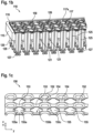
- a cut perspective view of the connector block 110 is shown in Fig. 1b .
- the connector block comprises a connector plate 115, which in the depicted example comprises apertures for accommodating an array of 12 * 8 connectors.
- the connectors 120 have an upper collar 121 that is supported on an upper surface 116 of the connector plate 115, whereby a main body of each connector extends through the connector plate.
- Each connector is provided with an internal passageway 125 that extends through the connector from a first end to a second end, whereby the first end is defined as the end where an entrance 126 to each internal passageway is located.
- a second end of each connector is suitably provided with a seal 127 for providing an airtight connection with the internal diameter of a pipetting tip, when the connector block is lowered to pick up an array of tips that are supported on a tray.
- the multichannel head is further provided with a sealing mat 150 in accordance with the invention, which will be described in detail later.
- Liquid is aspirated and then dispensed with the aid of a plunger block 130, comprising an array of 12 * 8 plungers 135 that are displaceable within channels that extend through the plunger block.
- the internal passageway 125 of each connector 120 is in fluid communication with an opening 132 in each channel of the plunger block that accommodates the corresponding plunger 135.
- each plunger 135 is connected to a piston plate 140.
- the piston plate is moveably coupled to a fixed part of the multichannel head via a first displacement mechanism, driven by a first motor (not shown).
- the first displacement mechanism comprises an arrangement of three spindles 145, which are driven in a known manner by a belt and pulley system (generally indicated with reference numeral 147).
- the depicted device further comprises a second displacement mechanism driven by a second motor 180, for moving an ejection plate 170 downward, relative to the connector plate 115, so as to push off the attached pipetting tips after use.
- the multichannel head 100 is preferably equipped with capacitive liquid level detection, so as to enable the aspiration of precise amounts of liquid.
- the details of the detection system are not relevant.
- the connector block in the depicted embodiment is electrically isolated from the plunger block and the multichannel head is provided with an isolation plate 160 made of an electrically non-conducting material that is arranged between the plunger block 130 and the connector block 110.
- the isolation plate 160 comprises an array 12 * 8 of bores 165 which are in fluid communication with the opening 132 of each corresponding channel of the plunger block and with the entrance 126 to the internal passageway 125 of each corresponding connector 120.
- the multichannel head may be equipped with capacitive liquid level detection without the need for an isolation plate 160.
- the connector block is directly mounted to the plunger block, such that the internal passageway 125 of each connector is in direct fluid communication with the opening 132 of each corresponding plunger channel. In both cases, a fluid space is created between each plunger channel and a pipetting tip that is attached to a corresponding connector. As will be understood, it is necessary for the fluid space to be sealed in an airtight manner.
- a first plurality of individual O-rings could be arranged at each interface between the internal passageway 125 of a connector 120 and the opening 132 to the corresponding plunger block channel.
- the device is equipped with at least one sealing mat that removes the need for a plurality of individual O-rings, thereby significantly reducing the time needed to assemble the multichannel head device.
- the device is equipped with a first and a second sealing mat.
- FIG. 1c An example of part of a sealing mat 150 according a first embodiment is shown in Fig. 1c .
- the mat comprises an array of annular sealing elements 152 made of an elastomeric material such as EPDM rubber.
- the multichannel head device of Fig. 1a has 96 channels and is configured for use in conjunction with a 96-well microplate with a centre-to-centre distance of 9 mm.
- the sealing mat has eight rows of twelve annular sealing elements 152 with a corresponding centre-to-centre distance of 9.0 mm. Adjacent sealing elements are interconnected by a lattice of linkages which extend in longitudinal direction y and in lateral direction x.
- Each annular sealing element has a thickness in vertical direction z that is greater than a thickness of the laterally extending linkages 154 and the longitudinally extending linkages 153 of the interconnecting lattice. Furthermore, a cut-out region 155 is formed between two opposing lateral linkages 154 and two opposing longitudinal linkages 153.
- the sealing mat may be formed in a moulding process.
- the linkages 153, 154 of interconnecting lattice may be formed from the same material as the sealing elements 152 or may be formed from a second material.
- the second material may be a polymer such as polyethylene or polypropylene, which is relatively stiffer.
- each cut-out region 155 reduces the amount of material needed for the interconnecting lattice and, in combination with suitable milling of an interface surface on which the sealing mat is arranged, enable the contact surface area between opposing surfaces to be increased when the head device is in assembled condition. This will be explained later.
- each cut-out region has opposing lateral edges 155a and opposing longitudinal edges 155b, which are straight. Between each lateral edge and a neighbouring longitudinal edge, the cut-out region 155 comprises a curved section 155c that corresponds to a part of the interconnecting lattice that surrounds the annular sealing element.
- the cut-out region may be circular, oval, or octagonal in shape.
- a sealing mat as shown in Fig. 1c is arranged on the upper surface 116 of the connector plate 115.
- the annular sealing elements of the mat have a thickness of 1.0 mm and the linkages of the interconnecting lattice have a smaller thickness of e.g. 0.3 mm.
- the connector block 110 is mounted to the plunger block 130 via the isolation plate 160.
- each of these parts is provided with coaxial connection holes for e.g. a bolted connection, to enable precise positioning of the parts relative to each other.
- the upper surface 116 of the connector plate is clamped against the underside of the isolation plate 160, so as to compress the annular sealing elements 152 of the mat, which surround the entrance 126 to the internal passageway of each connector 120. Due to the smaller thickness of the interconnecting lattice of the mat, the clamping force required to compress the sealing elements 152 is no greater than would have been needed for 96 individual O-rings, although the assembly time is considerably reduced.
- the connector plate is further adapted such that the sealing mat may be precisely located on the upper surface 116.
- the connector plate comprises protrusions 117 and corresponding recessed portions that are milled into the upper surface.
- the protrusions are identical in shape to the cut-out regions 155 of the sealing mat and have a flat top surface 117s that is in contact with the underside of the isolation plate 160 when the connector block is bolted to the plunger block.
- the protrusions 117 may have a "height" relative to the recessed portions of 0.75 mm and in mounted condition the annular sealing elements are compressed to a thickness of 0.8 mm.
- the cut-out regions in the sealing mat enable the top surface 117s of the protrusions to be in contact with the underside of the isolation plate 160. A relatively large contact surface area between these opposing surfaces is advantageous in terms of increasing stability.
- the isolation plate 160 has a flat underside.
- the underside is milled to comprise recessed portions and protrusions for locating the sealing mat and increasing the contact surface area.
- the isolation plate also has a flat top side in the depicted example and the underside of the plunger block is adapted to receive a second sealing mat according to the invention.
- the second sealing mat is identical to the mat shown in Fig. 1c and as described with reference to Fig. 1b .
- FIG. 1d A perspective view of the underside of the plunger block is shown in Fig. 1d .
- the lower surface 133 of the plunger block 130 has been milled to a depth of 0.75 mm so as to create protrusions 137 that are shaped to pass through the cut-out regions 155 of the second sealing mat.
- the lower surface is further milled such that the openings 132 to each plunger channel are provided in a raised annular portion that will be surrounded by the corresponding annular sealing element 152 of the mat.
- the annular sealing elements are compressed to a thickness of 0.8 mm and provide an airtight connection between the opening 132 to each plunger channel and the corresponding entrance to each bore 165 in the isolation plate 160.
- the thickness of the annular sealing elements and the milled depth of the surface on which the sealing mat is arranged. It is also possible for the upper surface of the isolation plate to be milled so as to receive the second sealing mat and the plunger block may have a flat underside.
- FIG. 2 An example of a further embodiment of a sealing mat according to the invention is depicted in Fig 2 .
- the sealing mat 250 is made from a single sheet of elastomeric material of uniform thickness.
- the mat in the depicted example comprises an array of 12 * 8 annular sealing elements 252 which, in use, are compressed to provide an airtight connection between the openings to the plunger block and the corresponding internal passageway 125 of the connectors (in embodiments without an isolation plate), or to provide an airtight connection between the bores 165 in the isolation plate and the corresponding plunger block opening / connector internal passageway.
- the annular sealing elements 252 are interconnected by a lattice of linkages that extend in longitudinal direction y and lateral direction x. As before, the interconnecting lattice creates cut-out regions 255 formed between two opposing longitudinal linkages 253 and two opposing lateral linkages 254.
- Such a sealing mat is suitable for arrangement on the connector block 110 shown in Fig. 1b and on the plunger block 130 shown in Fig. 1d .
- the size of the cut-out regions is maximized, to minimise the amount of material needed and so that the surface area of the mat which needs to be compressed is minimised.
- the longitudinal linkages 253 have a width in lateral direction x and the lateral linkages 254 have a width in longitudinal direction y that is considerably smaller, e.g. at least 50% smaller, preferably 75% smaller, than an outer diameter of the annular sealing elements 252.
- a sealing mat in accordance with the invention significantly reduces assembly time and enables the device to be assembled with the application of relatively low clamping forces.
- any reference signs placed between parentheses shall not be construed as limiting the claim.
- Use of the verb "comprise” and its conjugations does not exclude the presence of elements or steps other than those stated in a claim.
- the article "a” or “an” preceding an element does not exclude the presence of a plurality of such elements.
- the invention may be implemented by means of hardware comprising several distinct elements, and by means of a suitably programmed computer. In the device claim enumerating several means, several of these means may be embodied by one and the same item of hardware. The mere fact that certain measures are recited in mutually different dependent claims does not indicate that a combination of these measures cannot be used to advantage.
Landscapes
- Health & Medical Sciences (AREA)
- Clinical Laboratory Science (AREA)
- Chemical & Material Sciences (AREA)
- Chemical Kinetics & Catalysis (AREA)
- Automatic Analysis And Handling Materials Therefor (AREA)
- Devices For Use In Laboratory Experiments (AREA)
Abstract
Description
- The invention relates to a multichannel head of a pipetting device and is more particularly directed to a sealing arrangement for providing an airtight connection between openings in a plunger block of the multichannel head and connectors which provide a fluid space between a plunger and a pipetting tip that is attachable to a connector.
- Multichannel pipetting heads are well known in the art. An example of 96 channel device is disclosed in
US10821434 - Assembly time can be reduced via the use of a sealing gasket comprising multiple apertures. The use of such a gasket is disclosed in
US6244119 , which describes a multichannel pipette system including a multichannel pipettor and novel pipette tips having a crown that can be fitted over the opening of more than one channel. The pipettor comprises channel support plates and a tip seal gasket arranged between the crown of a pipette and the channel support plate. The tip seal gasket may be formed from a sheet of elastomeric material. - In a multichannel pipetting head comprising a plunger block and a connector block for the attachment of e.g. 96 pipetting tips, the arrangement of such a sheet between the plunger block and the connector block for providing an airtight seal between their respective openings would require large clamping forces.
- Consequently, there is a need for an improved sealing arrangement for such a multichannel pipetting head that enables reduced assembly time and the application of relatively low clamping forces.
- The present invention resides in a multichannel head of a pipetting device for aspirating and dispensing liquid via a plurality of pipetting tips. The multichannel head comprises a connector block having an array of m*n connectors, whereby each connector comprises an internal passageway that is fluidically connectable to a pipetting tip, and further includes a plunger block having a corresponding array of m*n channels. Each channel accommodates a plunger and has an opening that is fluidically connected to the internal passageway of a corresponding connector.
- In accordance with the invention, the multichannel head further comprises at least one sealing mat arranged between the connector block and the plunger block, wherein the at least one sealing mat comprises a corresponding array of m*n annular sealing elements made of an elastomeric material, for providing an airtight seal of the fluidic connection between the internal passageway of each connector and each opening of the corresponding plunger channel. The annular sealing elements are interconnected by a lattice of linkages that extend in lateral direction and in longitudinal direction, such that a cut-out region is formed between two opposing lateral linkages and two opposing longitudinal linkages.
- The annular sealing elements are arranged coaxially with the internal passageway of each connector and with the corresponding opening in the plunger block, and are compressed when the at least one sealing mat is clamped between opposing surfaces of the connector block and the plunger block. In one embodiment, the sealing mat has a uniform thickness and if formed of a single piece. Suitable materials include EPDM rubber and vulcanised thermoplastic elastomers. The cut-out regions of the interconnecting lattice reduce the surface area of the sealing mat that is compressed between the opposing surfaces and thereby reduces the required clamping forces.
- In a further embodiment, the annular sealing elements have a thickness that is greater than that of the interconnecting lattice. Only the annular sealing elements are compressed between the opposing surfaces in order to provide an airtight connection, which again reduces the required clamping forces. Advantageously, the interconnecting lattice may be formed from a second material of greater stiffness than the elastomeric material of the annular sealing elements. In one example, the interconnecting lattice is formed from a polymer material that is moulded to the annular sealing elements. Suitable elastomeric materials for the sealing elements include EPDM rubber and vulcanised thermoplastic elastomers (TPE-V) such as dynamically vulcanised EPDM and polypropylene blends. The interconnecting lattice may be made from the same material or from polyethylene, polypropylene or other suitable material. In some examples, where a relatively high stiffness is desirable for the interconnecting lattice, the second material may comprise thin metal inlays.
- In an embodiment, the multichannel head comprises 96 channels and an array of 12 * 8 plungers and connectors. The at least one sealing mat then comprises an array of 12*8 annular sealing elements with a centre-to-centre distance of 9.0 mm. In a further embodiment, the multichannel head comprises 384 channels and array of 24*16 plungers and connectors. The at least one sealing mat then comprises an array of 24*16 annular sealing elements with a centre-to-centre distance of 4.5 mm. In a further embodiment, the multichannel head comprises 1536 channels and array of 48*32 plungers and connectors. The at least one sealing mat then comprises an array of 48*32 annular sealing elements with a centre-to-centre distance of 2.25 mm. In a still further embodiment, the multichannel head comprises 24 channels and an array of 6*4 plungers and connectors. The at least one sealing mat then comprises an array of 6*4 annular sealing elements with a centre-to-centre distance of 18.0 mm.
- The number of channels of the multichannel head depends on the type of microplate that is used in the pipetting process, i.e. a 96-well, a 284-well, a 1536-well or a 24-well microplate. The wells have specific centre-to-centre distances, which correspond to the centre-to-centre distances mentioned above, and which are defined for the various types of microplate in the standard "ANSI SLAS 4-2004 (R2012), For microplates - Well positions", the contents of which are incorporated by reference.
- Suitably, the m*n plungers of the plunger block are connected to a piston plate of the multichannel head, which is displaced in vertical direction so as to displace the plungers for generating a negative pressure or a positive pressure. The piston plate may be mounted to a linear displacement mechanism such as arrangement of spindles which are driven by a motor and e.g. a belt and pulley arrangement.
- The connector block comprises a connector plate having an upper surface that is sealed against an opposing surface. In some examples, the connector plate has an array of apertures for supporting connectors. A first end of each connector may have a collar that rests on the upper surface of the connector plate, whereby a main body of the connector extends through the aperture. A second end of the connector is adapted for attachment of a pipetting tip and is suitably provided with a seat for a ring seal that engages with the internal diameter of a pipetting tip. In other examples, the apertures in the connector plate are provided with a screw thread and the first end of each connector has a corresponding thread.
- In further examples, the connecting plate has apertures which form a bore for the direct attachment of pipetting tips which are provided with connection features such as guiding ribs and sealing rings arranged on an outer diameter of the tip. The bore of each aperture then constitutes the "connector" of the connector block having an internal passageway in fluid communication with an attached pipetting tip.
- In the aforementioned examples, the connector block of the multichannel head is configured to pick up an array of pipetting tips via engagement between the connector and an internal or external diameter of an individual pipetting tip. It is also possible for the underside of the connection plate to be adapted to pick up an array of pipetting tips which are held in a block. The connectors then engage with fluid channels in the block.
- In an embodiment of the invention, the connector block is mounted directly to the plunger block, e.g. via a bolted connection, and comprises one sealing mat as described above.
- In one example, the sealing mat is provided on the upper surface of the connector plate. Advantageously, the upper surface is milled so as to comprise protrusions and recessed portions. The protrusions are shaped to pass through the cut-out regions of the sealing mat. Preferably, the protrusions have the same shape as the cut-out regions so as to precisely locate the sealing mat during assembly. In assembled condition, the annular sealing elements are compressed against the underside of the plunger block, which may be a flat surface. The cut-out regions also serve to increase the contact surface area between the underside of the plunger block and opposing surfaces of the connector plate in assembled condition, which is advantageous in terms of improving stability.
- Alternatively, the sealing mat may be provided on the underside of the plunger block, which, in the manner described above, is milled so as to comprise protrusions that pass through the cut-out regions of the sealing mat. The upper surface of the connector plate may then be a flat surface.
- In a further embodiment of a multichannel pipetting head according to the invention, the head is equipped with capacitive liquid level detection, so as to enable the aspiration and dispensing of precise amounts of liquid. The details of the detection system are not relevant for the present invention, except for a possible requirement that the connector block is electrically isolated from the plunger block. In such embodiments, the multichannel head is provided with an isolation plate made of an electrically non-conducting material that is arranged between the connector block and the plunger block.
- The isolation plate comprises an array of m*n bores that are coaxial with each opening of the corresponding plunger channel and each internal passageway of the corresponding connector. Furthermore, the multichannel head is provided with a first sealing mat between the plunger block and an upper surface of the isolation plate and with a second sealing mat arranged between the connector block and a lower surface of the isolation plate.
- In some examples, the isolation plate has flat surfaces and the underside of the plunger block has a milled surface with protrusions and recesses as described above for locating the first sealing mat and increasing the contact surface area between the plunger block and the isolation plate. The upper surface of the connector plate is milled in a corresponding fashion for locating the second sealing mat and increasing the contact surface area between the isolation plate and the connector plate. It is also possible for the upper surface of the isolation plate to comprise protrusions and recessed portions for locating the first sealing mat and/or for the underside of the isolation plate to comprise protrusions and recessed portions for locating the second sealing mat.
- In a further aspect, the invention relates to a sealing mat for a multichannel pipetting head in accordance with the embodiments described above.
- The sealing mat comprises an array of m*n annular sealing elements made of an elastomeric material, which are interconnected by a lattice of linkages that extend in lateral direction x and longitudinal direction y, such that a cut-out region is formed between two opposing lateral linkages and two opposing longitudinal linkages.
- In a first example, m*n = 96 and a centre-to-centre distance between adjacent annular sealing elements is 9.0 mm.
- In a second example, m*n = 384 and the centre-to-centre distance between adjacent annular sealing elements is 4.5 mm.
- In a third example, m*n = 1536 and the centre-to-centre distance between adjacent annular sealing elements is 2.25 mm.
- In a fourth example, m*n = 24 and the centre-to-centre distance between adjacent annular sealing elements is 18.0 mm.
- The annular sealing elements of the sealing mat may have a torus with any suitable geometric cross-section. Suitable geometries include circular, oval, x-shaped and triangular cross-section.
- The use of a sealing mat in accordance with the invention in a multichannel pipetting head significantly reduces assembly time and allows the pipetting head to be assembled with the application of "normal" clamping forces.
- These and other aspects of the invention are apparent from and will be elucidated with reference to the embodiments described hereinafter and with reference to the accompanying drawings.
-
- Fig. 1a
- is a cross-sectional view of an example of a multichannel pipetting head in accordance with the invention
- Fig. 1b
- is cut perspective view of a connector block of the multichannel head depicted in
Fig. 1a ; - Fig. 1c
- is a cut perspective view of part of a sealing mat according to a first embodiment;
- Fig. 1d
- is a perspective view of an underside of a plunger block of the multichannel head depicted in
fig. 1a ; - Fig. 2
- is a perspective view of an example of a sealing mat according to a second embodiment.
- It should be noted that items which have the same reference numbers in different figures, have the same structural features and the same functions. Where the function and/or structure of such an item has been explained, there is no necessity for repeated explanation thereof in the detailed description.
-
Figure 1a shows a cross-sectional view of amultichannel head device 100 according to an embodiment of the invention, which forms part of a liquid handling apparatus that may be used in a laboratory environment to dispense liquid via an array of disposable tips that are attachable toindividual connectors 120, which form part of a connector block of the device. A cut perspective view of theconnector block 110 is shown inFig. 1b . The connector block comprises aconnector plate 115, which in the depicted example comprises apertures for accommodating an array of 12 * 8 connectors. Theconnectors 120 have anupper collar 121 that is supported on anupper surface 116 of theconnector plate 115, whereby a main body of each connector extends through the connector plate. Each connector is provided with aninternal passageway 125 that extends through the connector from a first end to a second end, whereby the first end is defined as the end where anentrance 126 to each internal passageway is located. A second end of each connector is suitably provided with aseal 127 for providing an airtight connection with the internal diameter of a pipetting tip, when the connector block is lowered to pick up an array of tips that are supported on a tray. To provide an airtight seal at theentrance 126 to each connectorinternal passageway 125, the multichannel head is further provided with a sealingmat 150 in accordance with the invention, which will be described in detail later. - Liquid is aspirated and then dispensed with the aid of a
plunger block 130, comprising an array of 12 * 8 plungers 135 that are displaceable within channels that extend through the plunger block. Theinternal passageway 125 of eachconnector 120 is in fluid communication with anopening 132 in each channel of the plunger block that accommodates the corresponding plunger 135. To provide the displacement and generate negative/positive pressure, each plunger 135 is connected to apiston plate 140. The piston plate is moveably coupled to a fixed part of the multichannel head via a first displacement mechanism, driven by a first motor (not shown). In the depicted example, the first displacement mechanism comprises an arrangement of threespindles 145, which are driven in a known manner by a belt and pulley system (generally indicated with reference numeral 147). The depicted device further comprises a second displacement mechanism driven by asecond motor 180, for moving anejection plate 170 downward, relative to theconnector plate 115, so as to push off the attached pipetting tips after use. - The
multichannel head 100 is preferably equipped with capacitive liquid level detection, so as to enable the aspiration of precise amounts of liquid. The details of the detection system are not relevant. To facilitate the capacitive measurements, the connector block in the depicted embodiment is electrically isolated from the plunger block and the multichannel head is provided with anisolation plate 160 made of an electrically non-conducting material that is arranged between theplunger block 130 and theconnector block 110. Theisolation plate 160 comprises an array 12 * 8 ofbores 165 which are in fluid communication with theopening 132 of each corresponding channel of the plunger block and with theentrance 126 to theinternal passageway 125 of eachcorresponding connector 120. - In other embodiments, the multichannel head may be equipped with capacitive liquid level detection without the need for an
isolation plate 160. In such embodiments, the connector block is directly mounted to the plunger block, such that theinternal passageway 125 of each connector is in direct fluid communication with theopening 132 of each corresponding plunger channel. In both cases, a fluid space is created between each plunger channel and a pipetting tip that is attached to a corresponding connector. As will be understood, it is necessary for the fluid space to be sealed in an airtight manner. In the depicted embodiment, comprising theisolation plate 160, this could be achieved via a first plurality of individual O-rings arranged at each interface between the opening 132 to a plunger block channel and thecorresponding bore 165 of theisolation plate 160 and a second plurality of individual O-rings arranged at each interface between theinternal passageway 125 of aconnector 120 and thecorresponding bore 165 of the isolation plate. In embodiments without the isolation plate, a first plurality of individual O-rings could be arranged at each interface between theinternal passageway 125 of aconnector 120 and theopening 132 to the corresponding plunger block channel. - In accordance with the invention, the device is equipped with at least one sealing mat that removes the need for a plurality of individual O-rings, thereby significantly reducing the time needed to assemble the multichannel head device.
- In the embodiment depicted in
Fig. 1a , the device is equipped with a first and a second sealing mat. - An example of part of a sealing
mat 150 according a first embodiment is shown inFig. 1c . The mat comprises an array ofannular sealing elements 152 made of an elastomeric material such as EPDM rubber. The multichannel head device ofFig. 1a has 96 channels and is configured for use in conjunction with a 96-well microplate with a centre-to-centre distance of 9 mm. The sealing mat has eight rows of twelveannular sealing elements 152 with a corresponding centre-to-centre distance of 9.0 mm. Adjacent sealing elements are interconnected by a lattice of linkages which extend in longitudinal direction y and in lateral direction x. Each annular sealing element has a thickness in vertical direction z that is greater than a thickness of the laterally extendinglinkages 154 and thelongitudinally extending linkages 153 of the interconnecting lattice. Furthermore, a cut-outregion 155 is formed between two opposinglateral linkages 154 and two opposinglongitudinal linkages 153. - Advantageously, the sealing mat may be formed in a moulding process. The
linkages elements 152 or may be formed from a second material. The second material may be a polymer such as polyethylene or polypropylene, which is relatively stiffer. - The cut-out
regions 155 reduce the amount of material needed for the interconnecting lattice and, in combination with suitable milling of an interface surface on which the sealing mat is arranged, enable the contact surface area between opposing surfaces to be increased when the head device is in assembled condition. This will be explained later. In the example depicted inFig. 1c , each cut-out region has opposinglateral edges 155a and opposinglongitudinal edges 155b, which are straight. Between each lateral edge and a neighbouring longitudinal edge, the cut-outregion 155 comprises acurved section 155c that corresponds to a part of the interconnecting lattice that surrounds the annular sealing element. Such a geometry minimises the amount of material needed for the lattice. Other geometries are possible. For example, the cut-out region may be circular, oval, or octagonal in shape. - Returning to
Fig. 1b , a sealing mat as shown inFig. 1c is arranged on theupper surface 116 of theconnector plate 115. In the depicted example, the annular sealing elements of the mat have a thickness of 1.0 mm and the linkages of the interconnecting lattice have a smaller thickness of e.g. 0.3 mm. Theconnector block 110 is mounted to theplunger block 130 via theisolation plate 160. Suitably, each of these parts is provided with coaxial connection holes for e.g. a bolted connection, to enable precise positioning of the parts relative to each other. Theupper surface 116 of the connector plate is clamped against the underside of theisolation plate 160, so as to compress theannular sealing elements 152 of the mat, which surround theentrance 126 to the internal passageway of eachconnector 120. Due to the smaller thickness of the interconnecting lattice of the mat, the clamping force required to compress the sealingelements 152 is no greater than would have been needed for 96 individual O-rings, although the assembly time is considerably reduced. - The connector plate is further adapted such that the sealing mat may be precisely located on the
upper surface 116. The connector plate comprisesprotrusions 117 and corresponding recessed portions that are milled into the upper surface. The protrusions are identical in shape to the cut-outregions 155 of the sealing mat and have a flattop surface 117s that is in contact with the underside of theisolation plate 160 when the connector block is bolted to the plunger block. Theprotrusions 117 may have a "height" relative to the recessed portions of 0.75 mm and in mounted condition the annular sealing elements are compressed to a thickness of 0.8 mm. The cut-out regions in the sealing mat enable thetop surface 117s of the protrusions to be in contact with the underside of theisolation plate 160. A relatively large contact surface area between these opposing surfaces is advantageous in terms of increasing stability. - In the depicted example, the
isolation plate 160 has a flat underside. In other examples, the underside is milled to comprise recessed portions and protrusions for locating the sealing mat and increasing the contact surface area. The isolation plate also has a flat top side in the depicted example and the underside of the plunger block is adapted to receive a second sealing mat according to the invention. The second sealing mat is identical to the mat shown inFig. 1c and as described with reference toFig. 1b . - A perspective view of the underside of the plunger block is shown in
Fig. 1d . Thelower surface 133 of theplunger block 130 has been milled to a depth of 0.75 mm so as to createprotrusions 137 that are shaped to pass through the cut-outregions 155 of the second sealing mat. Suitably, the lower surface is further milled such that theopenings 132 to each plunger channel are provided in a raised annular portion that will be surrounded by the correspondingannular sealing element 152 of the mat. When the connector block is mounted to the plunger block, the annular sealing elements are compressed to a thickness of 0.8 mm and provide an airtight connection between the opening 132 to each plunger channel and the corresponding entrance to each bore 165 in theisolation plate 160. As will be understood, other dimensions are possible for the thickness of the annular sealing elements and the milled depth of the surface on which the sealing mat is arranged. It is also possible for the upper surface of the isolation plate to be milled so as to receive the second sealing mat and the plunger block may have a flat underside. - An example of a further embodiment of a sealing mat according to the invention is depicted in
Fig 2 . The sealingmat 250 is made from a single sheet of elastomeric material of uniform thickness. The mat in the depicted example comprises an array of 12 * 8annular sealing elements 252 which, in use, are compressed to provide an airtight connection between the openings to the plunger block and the correspondinginternal passageway 125 of the connectors (in embodiments without an isolation plate), or to provide an airtight connection between thebores 165 in the isolation plate and the corresponding plunger block opening / connector internal passageway. - The
annular sealing elements 252 are interconnected by a lattice of linkages that extend in longitudinal direction y and lateral direction x. As before, the interconnecting lattice creates cut-outregions 255 formed between two opposinglongitudinal linkages 253 and two opposinglateral linkages 254. Such a sealing mat is suitable for arrangement on theconnector block 110 shown inFig. 1b and on theplunger block 130 shown inFig. 1d . Advantageously, the size of the cut-out regions is maximized, to minimise the amount of material needed and so that the surface area of the mat which needs to be compressed is minimised. Suitably, thelongitudinal linkages 253 have a width in lateral direction x and thelateral linkages 254 have a width in longitudinal direction y that is considerably smaller, e.g. at least 50% smaller, preferably 75% smaller, than an outer diameter of theannular sealing elements 252. - In order to further reduce the clamping force that is required to compress the annular sealing elements, it is also possible to mill the surface on which the mat is arranged such that the linkages are accommodated in portions of the surface which are somewhat deeper relative to portions of the surface on which the
annular sealing elements 252 rest. - Thus, the use of a sealing mat in accordance with the invention in a multichannel head device significantly reduces assembly time and enables the device to be assembled with the application of relatively low clamping forces.
- Examples, embodiments or optional features, whether indicated as non-limiting or not, are not to be understood as limiting the invention as claimed. It should be noted that the above-mentioned embodiments illustrate rather than limit the invention, and that those skilled in the art will be able to design many alternative embodiments without departing from the scope of the appended claims.
- In the claims, any reference signs placed between parentheses shall not be construed as limiting the claim. Use of the verb "comprise" and its conjugations does not exclude the presence of elements or steps other than those stated in a claim. The article "a" or "an" preceding an element does not exclude the presence of a plurality of such elements. The invention may be implemented by means of hardware comprising several distinct elements, and by means of a suitably programmed computer. In the device claim enumerating several means, several of these means may be embodied by one and the same item of hardware. The mere fact that certain measures are recited in mutually different dependent claims does not indicate that a combination of these measures cannot be used to advantage.
- The following list of references and abbreviations is provided for facilitating the interpretation of the drawings and shall not be construed as limiting the claims.
- 100
- multi-channel pipetting head
- 110
- connector block
- 115
- connector plate
- 116
- upper surface of connector plate
- 117
- shaped protrusion on upper surface of connector plate
- 117s
- top surface of protrusion
- 120
- connector
- 121
- upper collar of a connector
- 125
- internal passageway through connector
- 126
- entrance to internal passageway at first end of connector
- 127
- ring seal at second end of connector
- 130
- plunger block
- 132
- opening in channel of plunger block
- 133
- lower surface of plunger block
- 135
- plunger
- 137
- shaped protrusion on lower surface of plunger block
- 140
- piston plate of multichannel pipetting head
- 145
- spindle to which piston plate is moveably coupled
- 147
- belt and pulley arrangement for driving spindles
- 150, 250
- sealing mat
- 152, 252
- annular sealing element
- 153, 253
- longitudinal linkage that interconnects adjacent sealing elements in longitudinal direction (y)
- 154, 254
- lateral linkage that interconnects adjacent sealing elements in lateral direction (x)
- 155, 255
- cut-out region between two opposing lateral linkages and two opposing longitudinal linkages
- 155a
- lateral edge of cut-out region
- 155b
- longitudinal edge of cut-out regions
- 155c
- curved section of cut-out region
- 160
- isolation plate
- 165
- bore through isolation plate
- 170
- ejector plate
- 180
- motor for driving displacement mechanism to which ejection plate is moveably coupled
- x
- lateral direction
- y
- longitudinal direction
- z
- vertical direction
Claims (12)
- A multichannel head (100) of a pipetting device for aspirating and dispensing a liquid via a plurality of pipetting tips, the multichannel head comprising:- a connector block (110) comprising an array of m*n connectors (120), whereby each connector comprises an internal passageway (125) that is fluidically connectable to a pipetting tip, and- a plunger block (130) comprising a corresponding array of m*n channels, whereby each channel accommodates a plunger (135) and has an opening (132) that is fluidically connected to the internal passageway (125) of a corresponding connector (120);characterized in that the multichannel head further comprises at least one sealing mat (150, 250) arranged between the connector block (110) and the plunger block (130), wherein the at least one sealing mat comprises a corresponding array of m*n annular sealing elements (152, 252) made of an elastomeric material, for sealing the fluidic connection between the internal passageway (125) of each connector and each opening (132) of the corresponding channel of the plunger block, wherein the annular sealing elements (152, 252) are interconnected by a lattice of linkages that extend in lateral direction (x) and in longitudinal direction (y), such that a cut-out region (155, 255) is formed between two opposing lateral linkages (154, 254) and two opposing longitudinal linkages (153, 253).
- The multichannel head of claim 1, wherein the annular sealing elements (152) of the at least one sealing mat (150) have a thickness in vertical direction (z) which is greater than a thickness of the linkages (153, 154) of the interconnecting lattice.
- The multichannel head of claim 2, wherein the linkages (153, 154) of the interconnecting lattice are made of a second material, different from the elastomeric material of the annular sealing elements (152).
- The multichannel head of claim 1, wherein the at least one sealing mat (250) is of uniform thickness in vertical direction (z) and is formed of a single piece.
- The multichannel head of any preceding claim, wherein the plunger block (130) is directly mounted to the connector block (110), such that the at least one sealing mat (150, 250) is arranged between a lower surface (133) of the plunger block and an upper surface (116) of a connection plate (115) in which the connectors (120) are provided, and wherein one of said lower surface (133) and said upper surface (116) comprises protrusions (117, 137) which are shaped to pass through the cut-out regions (155, 255) of the at least one sealing mat (150, 250), such that recessed portions are created in the respective surface which locate the sealing mat.
- The multichannel head of any of claims 1 - 4, further comprising an isolation plate (160) made of an electrically non-conducting material, which is arranged between the connector block (110) and the plunger block (130), wherein the isolation plate comprises a corresponding array of m*n bores (165) in fluidic connection with the opening (132) of the corresponding channel in the plunger block (130) and with the internal passageway (125) of the corresponding connector (120), and wherein a first sealing mat (150, 250) is arranged between the connector block (110) and the isolation plate (160) and a second sealing mat (150, 250) is arranged between the isolation plate and the plunger block (130).
- The multichannel head of claim 6, wherein:• one of a lower surface of the isolation plate (160) and the upper surface (116) of the connector plate (115) comprises protrusions (117) which are shaped to pass through the cut-out regions (155, 255) of the first sealing mat (150, 250); and• one of an upper surface of the isolation plate (160) and the lower surface (133) of the plunger block (130) comprises protrusions (137) which are shaped to pass through the cut-out regions (155, 255) of the second sealing mat (150, 250).
- The multichannel head of any preceding claim wherein:• m = 12 and n = 8; or• m = 24 and n = 16; or• m = 48 and n = 32; or• m = 6 and n = 4.
- Sealing mat (150, 250) comprising an array of m*n annular sealing elements (152, 252) made of an elastomeric material, which are interconnected by a lattice of linkages that extend in lateral direction (x) and longitudinal direction (y), such that a cut-out region (155, 255) is formed between two opposing lateral linkages (154, 254) and two opposing longitudinal linkages (153, 253) wherein:• m*n = 96 and a centre-to-centre distance between adjacent annular sealing elements (152, 252) is 9.0 mm, or• m*n = 384 and the centre-to-centre distance between adjacent annular sealing elements is 4.5 mm, or• m*n = 1536 and the centre-to-centre distance between adjacent annular sealing elements is 2.25 mm, or• m*n = 24 and the centre-to-centre distance between adjacent annular sealing elements is 18.0 mm
- Sealing mat of claim 9, wherein the annular sealing elements (152) have a thickness in vertical direction (z) which is greater than a thickness of the linkages (153, 154) of the interconnecting lattice.
- Sealing mat of claim 10, wherein the linkages (153, 154) of the interconnecting lattice are made of a second material, different from the elastomeric material of the annular sealing elements (152).
- Sealing mat of claim 9, wherein the sealing mat (250) is of uniform thickness in vertical direction (z) and is formed of a single piece.
Priority Applications (5)
| Application Number | Priority Date | Filing Date | Title |
|---|---|---|---|
| EP22202905.0A EP4357023A1 (en) | 2022-10-21 | 2022-10-21 | Multichannel pipetting head |
| CN202380012583.7A CN118234568A (en) | 2022-10-21 | 2023-10-18 | Multichannel pipetting heads |
| PCT/EP2023/079013 WO2024083922A1 (en) | 2022-10-21 | 2023-10-18 | Multichannel pipetting head |
| US18/575,712 US20250073698A1 (en) | 2022-10-21 | 2023-10-18 | Multichannel pipetting head |
| EP23793739.6A EP4377014B1 (en) | 2022-10-21 | 2023-10-18 | Multichannel pipetting head |
Applications Claiming Priority (1)
| Application Number | Priority Date | Filing Date | Title |
|---|---|---|---|
| EP22202905.0A EP4357023A1 (en) | 2022-10-21 | 2022-10-21 | Multichannel pipetting head |
Publications (1)
| Publication Number | Publication Date |
|---|---|
| EP4357023A1 true EP4357023A1 (en) | 2024-04-24 |
Family
ID=83903015
Family Applications (2)
| Application Number | Title | Priority Date | Filing Date |
|---|---|---|---|
| EP22202905.0A Withdrawn EP4357023A1 (en) | 2022-10-21 | 2022-10-21 | Multichannel pipetting head |
| EP23793739.6A Active EP4377014B1 (en) | 2022-10-21 | 2023-10-18 | Multichannel pipetting head |
Family Applications After (1)
| Application Number | Title | Priority Date | Filing Date |
|---|---|---|---|
| EP23793739.6A Active EP4377014B1 (en) | 2022-10-21 | 2023-10-18 | Multichannel pipetting head |
Country Status (4)
| Country | Link |
|---|---|
| US (1) | US20250073698A1 (en) |
| EP (2) | EP4357023A1 (en) |
| CN (1) | CN118234568A (en) |
| WO (1) | WO2024083922A1 (en) |
Families Citing this family (1)
| Publication number | Priority date | Publication date | Assignee | Title |
|---|---|---|---|---|
| CN118874573B (en) * | 2024-09-27 | 2024-12-06 | 安徽安龙基因科技有限公司 | A reagent sampling device and nucleic acid detection integrated machine |
Citations (3)
| Publication number | Priority date | Publication date | Assignee | Title |
|---|---|---|---|---|
| US6244119B1 (en) | 1999-08-03 | 2001-06-12 | Wallac Oy | Multichannel pipette system and pipette tips therefor |
| US20100080733A1 (en) * | 2001-08-10 | 2010-04-01 | Symyx Technologies, Inc. | Needle assembly for aspirating and dispensing from sealed containers |
| US20170354965A1 (en) * | 2014-11-18 | 2017-12-14 | Avidien Technologies, Inc. | Multichannel air displacement pipettor |
Family Cites Families (5)
| Publication number | Priority date | Publication date | Assignee | Title |
|---|---|---|---|---|
| FI20002761A0 (en) * | 2000-12-15 | 2000-12-15 | Wallac Oy | Multi-channel pipette device |
| US20040071602A1 (en) * | 2002-10-15 | 2004-04-15 | Yiu Felix H. | Pipettor head adapter |
| US20180117584A1 (en) * | 2011-07-20 | 2018-05-03 | Avidien Technologies | Pipette tip adapter |
| DE102011053808A1 (en) * | 2011-09-20 | 2013-03-21 | Cybio Ag | Pipetting head with groups of Pipetierkanälen different diameters and device with such a pipetting head |
| CN105209922B (en) * | 2013-03-15 | 2017-06-09 | 道格拉斯科学有限责任公司 | Pass-Through Cleaning Pipettes |
-
2022
- 2022-10-21 EP EP22202905.0A patent/EP4357023A1/en not_active Withdrawn
-
2023
- 2023-10-18 US US18/575,712 patent/US20250073698A1/en active Pending
- 2023-10-18 WO PCT/EP2023/079013 patent/WO2024083922A1/en not_active Ceased
- 2023-10-18 CN CN202380012583.7A patent/CN118234568A/en active Pending
- 2023-10-18 EP EP23793739.6A patent/EP4377014B1/en active Active
Patent Citations (4)
| Publication number | Priority date | Publication date | Assignee | Title |
|---|---|---|---|---|
| US6244119B1 (en) | 1999-08-03 | 2001-06-12 | Wallac Oy | Multichannel pipette system and pipette tips therefor |
| US20100080733A1 (en) * | 2001-08-10 | 2010-04-01 | Symyx Technologies, Inc. | Needle assembly for aspirating and dispensing from sealed containers |
| US20170354965A1 (en) * | 2014-11-18 | 2017-12-14 | Avidien Technologies, Inc. | Multichannel air displacement pipettor |
| US10821434B2 (en) | 2014-11-18 | 2020-11-03 | Avidien Technologies, Inc. | Multichannel air displacement pipettor |
Also Published As
| Publication number | Publication date |
|---|---|
| WO2024083922A1 (en) | 2024-04-25 |
| US20250073698A1 (en) | 2025-03-06 |
| EP4377014A1 (en) | 2024-06-05 |
| CN118234568A (en) | 2024-06-21 |
| EP4377014B1 (en) | 2025-06-11 |
Similar Documents
| Publication | Publication Date | Title |
|---|---|---|
| EP1074302B1 (en) | Multichannel pipette system and pipette tips therefor | |
| US8071050B2 (en) | Ergonomic pipette tip and adapters | |
| US5765591A (en) | Valve apparatus and method for distributing fluids | |
| US11559802B2 (en) | Pipette tip adapter | |
| US8202495B1 (en) | Ergonomic pipette tip | |
| EP2734301B1 (en) | Pipette tip adapter | |
| US20220097038A1 (en) | Pipetting head, pipetting device comprising a pipetting head, and method for pipetting using a pipetting head | |
| EP4377014B1 (en) | Multichannel pipetting head | |
| CN103990502A (en) | Multichannel pipette | |
| US11890619B2 (en) | Sample and reagent containers with anti-vacuum feature | |
| AU3378600A (en) | Syringe array system and method | |
| US20180221864A1 (en) | Pipette Tip Loading and Unloading Mechanism for Single Row Multichannel Pipettors | |
| CN114733590B (en) | Pipetting device and pipetting workstation | |
| EP3974841B1 (en) | Multichannel pipetting device | |
| CN113877647B (en) | Multichannel pipetting head | |
| WO2022258995A2 (en) | Pipette tip for a liquid dispensing apparatus | |
| CN220715900U (en) | Large-scale volume high-precision pump-connected pipetting device | |
| CN118253360A (en) | Multichannel pipettor | |
| GB2639032A (en) | Pipetting head for a liquid dispensing apparatus | |
| US7919047B2 (en) | Air displacement pipetter | |
| EP1497031B1 (en) | Improved pipettor and externally sealed pipette tips |
Legal Events
| Date | Code | Title | Description |
|---|---|---|---|
| PUAI | Public reference made under article 153(3) epc to a published international application that has entered the european phase |
Free format text: ORIGINAL CODE: 0009012 |
|
| STAA | Information on the status of an ep patent application or granted ep patent |
Free format text: STATUS: THE APPLICATION HAS BEEN PUBLISHED |
|
| AK | Designated contracting states |
Kind code of ref document: A1 Designated state(s): AL AT BE BG CH CY CZ DE DK EE ES FI FR GB GR HR HU IE IS IT LI LT LU LV MC ME MK MT NL NO PL PT RO RS SE SI SK SM TR |
|
| P01 | Opt-out of the competence of the unified patent court (upc) registered |
Free format text: CASE NUMBER: APP_33740/2024 Effective date: 20240605 |
|
| STAA | Information on the status of an ep patent application or granted ep patent |
Free format text: STATUS: THE APPLICATION IS DEEMED TO BE WITHDRAWN |
|
| 18D | Application deemed to be withdrawn |
Effective date: 20241025 |