EP4357011A1 - Method and device for mixing gypsum granules derived from waste gypsum board and gypsum slurry - Google Patents
Method and device for mixing gypsum granules derived from waste gypsum board and gypsum slurry Download PDFInfo
- Publication number
- EP4357011A1 EP4357011A1 EP21946116.7A EP21946116A EP4357011A1 EP 4357011 A1 EP4357011 A1 EP 4357011A1 EP 21946116 A EP21946116 A EP 21946116A EP 4357011 A1 EP4357011 A1 EP 4357011A1
- Authority
- EP
- European Patent Office
- Prior art keywords
- gypsum
- slurry
- flow path
- pipe
- gypsum slurry
- Prior art date
- Legal status (The legal status is an assumption and is not a legal conclusion. Google has not performed a legal analysis and makes no representation as to the accuracy of the status listed.)
- Granted
Links
Images

Classifications
-
- C—CHEMISTRY; METALLURGY
- C01—INORGANIC CHEMISTRY
- C01F—COMPOUNDS OF THE METALS BERYLLIUM, MAGNESIUM, ALUMINIUM, CALCIUM, STRONTIUM, BARIUM, RADIUM, THORIUM, OR OF THE RARE-EARTH METALS
- C01F11/00—Compounds of calcium, strontium, or barium
- C01F11/46—Sulfates
-
- B—PERFORMING OPERATIONS; TRANSPORTING
- B28—WORKING CEMENT, CLAY, OR STONE
- B28C—PREPARING CLAY; PRODUCING MIXTURES CONTAINING CLAY OR CEMENTITIOUS MATERIAL, e.g. PLASTER
- B28C5/00—Apparatus or methods for producing mixtures of cement with other substances, e.g. slurries, mortars, porous or fibrous compositions
- B28C5/02—Apparatus or methods for producing mixtures of cement with other substances, e.g. slurries, mortars, porous or fibrous compositions without using driven mechanical means effecting the mixing
- B28C5/04—Gravitational mixing; Mixing by intermingling streams of ingredients
-
- B—PERFORMING OPERATIONS; TRANSPORTING
- B28—WORKING CEMENT, CLAY, OR STONE
- B28C—PREPARING CLAY; PRODUCING MIXTURES CONTAINING CLAY OR CEMENTITIOUS MATERIAL, e.g. PLASTER
- B28C1/00—Apparatus or methods for obtaining or processing clay
- B28C1/02—Apparatus or methods for obtaining or processing clay for producing or processing clay suspensions, e.g. slip
-
- B—PERFORMING OPERATIONS; TRANSPORTING
- B28—WORKING CEMENT, CLAY, OR STONE
- B28C—PREPARING CLAY; PRODUCING MIXTURES CONTAINING CLAY OR CEMENTITIOUS MATERIAL, e.g. PLASTER
- B28C5/00—Apparatus or methods for producing mixtures of cement with other substances, e.g. slurries, mortars, porous or fibrous compositions
- B28C5/003—Methods for mixing
-
- B—PERFORMING OPERATIONS; TRANSPORTING
- B28—WORKING CEMENT, CLAY, OR STONE
- B28C—PREPARING CLAY; PRODUCING MIXTURES CONTAINING CLAY OR CEMENTITIOUS MATERIAL, e.g. PLASTER
- B28C5/00—Apparatus or methods for producing mixtures of cement with other substances, e.g. slurries, mortars, porous or fibrous compositions
- B28C5/02—Apparatus or methods for producing mixtures of cement with other substances, e.g. slurries, mortars, porous or fibrous compositions without using driven mechanical means effecting the mixing
- B28C5/06—Apparatus or methods for producing mixtures of cement with other substances, e.g. slurries, mortars, porous or fibrous compositions without using driven mechanical means effecting the mixing the mixing being effected by the action of a fluid
-
- B—PERFORMING OPERATIONS; TRANSPORTING
- B28—WORKING CEMENT, CLAY, OR STONE
- B28C—PREPARING CLAY; PRODUCING MIXTURES CONTAINING CLAY OR CEMENTITIOUS MATERIAL, e.g. PLASTER
- B28C7/00—Controlling the operation of apparatus for producing mixtures of clay or cement with other substances; Supplying or proportioning the ingredients for mixing clay or cement with other substances; Discharging the mixture
- B28C7/0007—Pretreatment of the ingredients, e.g. by heating, sorting, grading, drying, disintegrating; Preventing generation of dust
-
- Y—GENERAL TAGGING OF NEW TECHNOLOGICAL DEVELOPMENTS; GENERAL TAGGING OF CROSS-SECTIONAL TECHNOLOGIES SPANNING OVER SEVERAL SECTIONS OF THE IPC; TECHNICAL SUBJECTS COVERED BY FORMER USPC CROSS-REFERENCE ART COLLECTIONS [XRACs] AND DIGESTS
- Y02—TECHNOLOGIES OR APPLICATIONS FOR MITIGATION OR ADAPTATION AGAINST CLIMATE CHANGE
- Y02W—CLIMATE CHANGE MITIGATION TECHNOLOGIES RELATED TO WASTEWATER TREATMENT OR WASTE MANAGEMENT
- Y02W30/00—Technologies for solid waste management
- Y02W30/50—Reuse, recycling or recovery technologies
- Y02W30/91—Use of waste materials as fillers for mortars or concrete
Definitions
- the present invention relates to the mixing of the gypsum granules derived from wasted gypsum boards and gypsum slurry.
- Patent Document 1 JP 6336385B
- a cylindrical mixing device 40 shown in Fig. 5 .
- the wasted gypsum boards are crushed, and then, the resultant gypsum is heated and converted to hemihydrate and/or anhydrous type III gypsum granules.
- the gypsum granules are fed into gypsum slurry 44 within the mixing device from a feed inlet 41.
- the slurry 44 containing dihydrate gypsum is fed in a tangential direction into the cylinder of the mixing device from a slurry inlet 42 on the side of the cylinder, and the slurry after the mixing is discharged from a slurry outlet 43 into a deposition tank.
- the slurry 44 is made to swirl in the mixing device 40 such that air is prevented from being entrained in the slurry 44. This prevents cavitation when the slurry is pumped from the mixing device 40 to the deposition tank.
- a pipe 45 is provided in the center.
- an exhaust port 47 is provided to prevent pressure buildup in the device.
- the mixing device 40 shown in Fig. 5 tends to generate scale 46 of gypsum, deposit of gypsum, on a range from the bottom portion of the mixing device to the side portion.
- This scale 46 sticks to the inner walls of the mixing device 40 tightly and is extremely hard. It is inefficient to periodically interrupt the operations of the mixing device to remove the scale. By the way, this phenomenon is not a part of prior art.
- JP 2020-105045A the inventors have proposed to suppress the formation of crystal nuclei and increase the particle size of the recovered dihydrate gypsum by reducing the time of the slurry staying in the mixing device.
- the inventors have described that the mixer is cylindrical, for example, but can be an open channel or the like.
- the problem to be solved by the invention is to suppress the generation of the gypsum scale in the device for mixing the gypsum granules derived from wasted gypsum boards with gypsum slurry.
- a mixing method comprises: a step for feeding hemihydrate and/or anhydrous type III gypsum granules derived from wasted gypsum boards into a flow path of aqueous gypsum slurry containing dihydrate gypsum and mixing said gypsum granules with the gypsum slurry; and a step for supplying the slurry after mixing to a deposition tank of dihydrate gypsum.
- the gypsum slurry is supplied into the flow path from an inlet of the flow path, said gypsum granules are fed from an above position into the gypsum slurry, and, after feeding said gypsum granules, the gypsum slurry is made to flow to an outlet of the flow path while an upper surface of the gypsum slurry is always exposed to air in the flow path.
- the gypsum slurry is fed from the outlet of the flow path into a pipe by free fall, and wherein the gypsum slurry is made to impinge on a far side surface of the pipe as viewed from the outlet and fall or the gypsum slurry is made to fall down a center portion of the pipe such that the gypsum slurry does not fall along the near side surface of the pipe as viewed from the outlet.
- a mixing device is one for mixing gypsum granules derived from wasted gypsum boards and gypsum slurry and supplying the slurry after mixing to a deposition tank of dihydrate gypsum.
- the device comprises a flow path and a pipe both for the gypsum slurry.
- the flow path is configured to receive the gypsum slurry from an inlet of the flow path, to receive said gypsum granules from an above position into the gypsum slurry, and, after receiving said gypsum granules, to flow the gypsum slurry to an outlet of the flow path while an upper surface of the gypsum slurry is always exposed to air in the flow path.
- the pipe is configured to receive the gypsum slurry freely falling from the outlet of the flow path and to make the gypsum slurry impinge on a far side surface of the pipe as viewed from the outlet and fall or make the gypsum slurry fall down a center portion of the pipe such that the gypsum slurry does not fall along the near side surface of the pipe as viewed from the outlet.
- gypsum scale is very hard and tough, and, in particular, annular gypsum scale is difficult to remove.
- the scale attaches to only a portion of the flow path or the pipe, rather than the entire circumference, namely, the entire inner surface, of them, the scale can be easily peeled off. If, in the flow path, the upper surface of the slurry is always exposed to air, then the scale does not adhere in an annular pattern, or in a ring-like pattern, in the flow path. Further, if the slurry is made to impinge on the far side of the pipe, or if the slurry is made to fall down the center portion of the pipe, no annular scale covering the 360 degree circumference does form.
- the gypsum scale attached to the mixing device can be easily removed.
- the flow path is straight.
- the flow path is U-shaped in cross-section, but it can be pipe-shaped, and it is important that the upper surface of the slurry is always exposed to air. Further, it is important that there is no point from the pipe to the deposition tank where the slurry expands 360 degrees and flows around the entire circumference of the flow path or the pipe, in a plane perpendicular to the flow direction. In the flow path with an open top surface, the top of the slurry is always exposed to air, and, in the pipe, the slurry flows along only part of the inner wall or in the center portion of the pipe.
- the cross-sectional shape perpendicular to the direction of the flow path is a curved surface such as a U-shaped one, rather than a rectangle having vertices at the corners. If the flow path has a vertex in its cross-section at a height lower than the upper surface of the slurry, the slurry tends to stay at the vertex and form scale.
- the flow path has a constant cross-sectional shape from the inlet to the outlet of the flow path. If the cross-sectional shape is not constant, the slurry easily stays to form the scale.
- a circular pipe is preferable to one having corners, and a pipe having a constant thickness is preferable. Polygonal pipes having corners easily form scale at the corners, and pipes having not constant thickness easily form scale.
- Gypsum granules are supplied to the deposition tank via the mixing device and are not directly fed to the deposition tank so that the scale is generated only within the mixing device. Further, according to the invention, when the slurry mixed with the gypsum granules arrives at the deposition tank, the scale is not generated, since the degree of super saturation decreases.
- the inner surfaces of the flow path and the pipe are covered with a film or a plate both made of fluororesin and the growth of gypsum scale on the inner surfaces is delayed.
- the fluororesin films and plates have a long service life in the gypsum slurry. Since the gypsum scale does not easily attach to the fluororesin films and plates, the growth of the scale is delayed.
- the gypsum slurry is fed from a feeding pipe to the flow path, and the flow path has a larger cross-section than the feeding pipe has such that the upper surface of the gypsum slurry in the flow path is always exposed to air.
- the cross-section of the flow path is the maximum cross-sectional area in which the slurry can flow and is not the cross-sectional area of the slurry.
- a flow path comprising a pipe has a cross-sectional area corresponding to the whole cross-sectional area inside the pipe. Further, if the 100% volume in the feeding pipe is occupied by the slurry, in the flow path having a larger cross-section than the feeding pipe, the upper surface of the slurry is exposed to air.
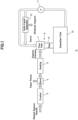
- FIG. 1 shows a recovery system 2 for recovering dihydrate gypsum from wasted gypsum boards. Wasted gypsum boards comprising cardboard paper and dihydrate gypsum are crushed by a crusher 3, and the resultant paper pieces and dihydrate gypsum are separated by a sieve 4. The dihydrate gypsum is then heated in a heating device 5 and converted into hemihydrate and/or anhydrous type III gypsum granules.
- the mixing device 6 comprises a flow path 7 and a pipe 8.
- the gypsum granules are fed into an aqueous slurry of dihydrate gypsum in the flow path 7, and the gypsum slurry after mixing is fed from the pipe 8 into a deposition tank 10.
- Dihydrate gypsum crystals are made grown in the gypsum slurry in the deposition tank 10, and the gypsum slurry is supplied by a fluid pump 11 to a solid-liquid separator 12 such as a filter press for separating dihydrate gypsum granules from the gypsum slurry.
- the remaining gypsum slurry is recirculated to the flow path 7.
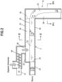
- Figs. 2 to 4 show the structures of the flow path 7 and the pipe 8. While the flow path 7 can include a bent portion where the flow of the aqueous slurry 23 containing dihydrate gypsum bends, preferably, the flow path is straight. While the flow path 7 is indicated horizontally in Fig. 2 , actually, it is inclined downward from an inlet 25 to an outlet 30 such that the accumulation of foreign matters such as gravel is prevented.
- the vertical cross-section of the flow path 7, perpendicular to the flow direction is, for example, U-shaped.
- the flow path 7 comprises a flow path main body 20, for example, made of stainless steel with a U-shaped cross-section and an inner lining 21 made of fluororesin.
- the lining 21 may be a film or a plate.
- the upper opening of the flow path 7 is, for example, covered by tread plates 22.
- the flow path 7 can be a pipe, and the slurry is made to flow, for example, in the lower 1/2 to 1/4 portion of the cross-section of the pipe, and, in the upper portion of the pipe, there is always present air over the slurry.
- the fluororesin lining 21 delays the growth of the gypsum scale. Further, the fluororesin lining 21 is highly durable in the gypsum slurry and is usable for more than one year, for example. In contrast, a lining made of soft polyvinyl chloride resin or the like has a service life of about half year in gypsum slurry. Further, the inner lining 21 may not be provided.
- the slurry 23 is fed through a pipe 24 into the flow path, and the joint between the pipe 24 and the flow path 7 is the inlet 25 of the flow path 7.
- a feeding device 26 such as a screw conveyor, feeds hemihydrate and/or anhydrous type III gypsum granules into the flow path 7.
- Indicated by 27 is a motor of the feeding device 26 and indicated by 28 is the feed port.
- the slurry in the pipe 24 and the flow path 7 has the velocity distributions shown schematically in Fig. 2 .
- the feed port 28 is located upstream of the center of the flow path 7 in the flow direction for promoting the mixing of the gypsum granules with the slurry.
- the gypsum slurry 23 flows at the bottom portion of the flow path 7, and the liquid surface 32 of the slurry 23 is always exposed to air 34, so that no annular scaling occurs in the flow path 7.
- the diameter of the pipe 24 is, for example, 100 mm to 200 mm
- the diameter of the flow path 7 is about twice the diameter of pipe 24, and the average velocity of slurry 23 in the flow path 7 is, for example, 2 to 4 m/sec.
- the slurry 23 falls freely into the pipe 8, and because of the high velocity, the slurry impinges on the opposite side of the pipe 8 as viewed from the flow path 7 and falls.
- the pipe 8 is preferably covered with an inner lining 31 comprising a fluororesin membrane or a fluororesin pipe on the inner surface of the pipe.
- slurry droplets attach on various parts of the pipe 8, however, as shown within the single-dotted line in Fig. 4 , the slurry 23 does not flow in such a way that the slurry expands in 360-degrees covering on the whole inner surface of the pipe 8. Further, the droplets attaching to the pipe 8 do not grow to the scale adhering in an annular pattern without gaps.
- the diameter of the pipe 8 is increased so that the slurry 23 falls down the center portion of pipe 8 without impinging the inner surface of the pipe.
- the diameter of the pipe 8 is about the same as the diameter of the flow path 7, for example.
- the direction of the pipe 8 is not limited to vertical.
- the gypsum slurry flows from the pipe 8 to the deposition tank 10. Between the pipe 8 and the deposition tank 10, there may be an additional flow path where the top of the liquid surface is always exposed to air, or there may be an additional pipe other than the pipe 8.
- the embodiment have the following advantageous features.
Landscapes
- Chemical & Material Sciences (AREA)
- Mechanical Engineering (AREA)
- Structural Engineering (AREA)
- Engineering & Computer Science (AREA)
- Dispersion Chemistry (AREA)
- Organic Chemistry (AREA)
- Physics & Mathematics (AREA)
- Fluid Mechanics (AREA)
- Geology (AREA)
- Inorganic Chemistry (AREA)
- Life Sciences & Earth Sciences (AREA)
- Preparation Of Clay, And Manufacture Of Mixtures Containing Clay Or Cement (AREA)
- Compounds Of Alkaline-Earth Elements, Aluminum Or Rare-Earth Metals (AREA)
Abstract
Description
- The present invention relates to the mixing of the gypsum granules derived from wasted gypsum boards and gypsum slurry.
- The present inventors have been studying the recovery of dihydrate gypsum from wasted gypsum boards. In Patent Document 1 (
JP 6336385B cylindrical mixing device 40 shown inFig. 5 . First the wasted gypsum boards are crushed, and then, the resultant gypsum is heated and converted to hemihydrate and/or anhydrous type III gypsum granules. Then, the gypsum granules are fed intogypsum slurry 44 within the mixing device from afeed inlet 41. Theslurry 44 containing dihydrate gypsum is fed in a tangential direction into the cylinder of the mixing device from aslurry inlet 42 on the side of the cylinder, and the slurry after the mixing is discharged from aslurry outlet 43 into a deposition tank. Theslurry 44 is made to swirl in themixing device 40 such that air is prevented from being entrained in theslurry 44. This prevents cavitation when the slurry is pumped from themixing device 40 to the deposition tank. Further, in order to prevent no-flow areas from occurring in the center of themixing device 40, apipe 45 is provided in the center. In addition, anexhaust port 47 is provided to prevent pressure buildup in the device. - However, the inventors have found that the
mixing device 40 shown inFig. 5 tends to generatescale 46 of gypsum, deposit of gypsum, on a range from the bottom portion of the mixing device to the side portion. Thisscale 46 sticks to the inner walls of themixing device 40 tightly and is extremely hard. It is inefficient to periodically interrupt the operations of the mixing device to remove the scale. By the way, this phenomenon is not a part of prior art. - Relevant pieces of the prior art will be described. In
JP 2020-105045A -
- Patent Document 1:
JP 6336385B - Patent Document 2:
JP 2020-105045A - The problem to be solved by the invention is to suppress the generation of the gypsum scale in the device for mixing the gypsum granules derived from wasted gypsum boards with gypsum slurry.
- A mixing method according to the invention comprises: a step for feeding hemihydrate and/or anhydrous type III gypsum granules derived from wasted gypsum boards into a flow path of aqueous gypsum slurry containing dihydrate gypsum and mixing said gypsum granules with the gypsum slurry; and a step for supplying the slurry after mixing to a deposition tank of dihydrate gypsum.
- According to the invention, the gypsum slurry is supplied into the flow path from an inlet of the flow path, said gypsum granules are fed from an above position into the gypsum slurry, and, after feeding said gypsum granules, the gypsum slurry is made to flow to an outlet of the flow path while an upper surface of the gypsum slurry is always exposed to air in the flow path.
- According to the invention, the gypsum slurry is fed from the outlet of the flow path into a pipe by free fall, and wherein the gypsum slurry is made to impinge on a far side surface of the pipe as viewed from the outlet and fall or the gypsum slurry is made to fall down a center portion of the pipe such that the gypsum slurry does not fall along the near side surface of the pipe as viewed from the outlet.
- A mixing device according to the invention is one for mixing gypsum granules derived from wasted gypsum boards and gypsum slurry and supplying the slurry after mixing to a deposition tank of dihydrate gypsum.
- The device comprises a flow path and a pipe both for the gypsum slurry.
- According to the invention, the flow path is configured to receive the gypsum slurry from an inlet of the flow path, to receive said gypsum granules from an above position into the gypsum slurry, and, after receiving said gypsum granules, to flow the gypsum slurry to an outlet of the flow path while an upper surface of the gypsum slurry is always exposed to air in the flow path.
- According to the invention, the pipe is configured to receive the gypsum slurry freely falling from the outlet of the flow path and to make the gypsum slurry impinge on a far side surface of the pipe as viewed from the outlet and fall or make the gypsum slurry fall down a center portion of the pipe such that the gypsum slurry does not fall along the near side surface of the pipe as viewed from the outlet.
- Generally, gypsum scale is very hard and tough, and, in particular, annular gypsum scale is difficult to remove. In contrast, if the scale attaches to only a portion of the flow path or the pipe, rather than the entire circumference, namely, the entire inner surface, of them, the scale can be easily peeled off. If, in the flow path, the upper surface of the slurry is always exposed to air, then the scale does not adhere in an annular pattern, or in a ring-like pattern, in the flow path. Further, if the slurry is made to impinge on the far side of the pipe, or if the slurry is made to fall down the center portion of the pipe, no annular scale covering the 360 degree circumference does form. Thus, according to the invention, the gypsum scale attached to the mixing device can be easily removed.
- Preferably the flow path is straight. In the embodiment, the flow path is U-shaped in cross-section, but it can be pipe-shaped, and it is important that the upper surface of the slurry is always exposed to air. Further, it is important that there is no point from the pipe to the deposition tank where the slurry expands 360 degrees and flows around the entire circumference of the flow path or the pipe, in a plane perpendicular to the flow direction. In the flow path with an open top surface, the top of the slurry is always exposed to air, and, in the pipe, the slurry flows along only part of the inner wall or in the center portion of the pipe.
- Preferably, the cross-sectional shape perpendicular to the direction of the flow path is a curved surface such as a U-shaped one, rather than a rectangle having vertices at the corners. If the flow path has a vertex in its cross-section at a height lower than the upper surface of the slurry, the slurry tends to stay at the vertex and form scale. Preferably, the flow path has a constant cross-sectional shape from the inlet to the outlet of the flow path. If the cross-sectional shape is not constant, the slurry easily stays to form the scale. Similarly, a circular pipe is preferable to one having corners, and a pipe having a constant thickness is preferable. Polygonal pipes having corners easily form scale at the corners, and pipes having not constant thickness easily form scale.
- Gypsum granules are supplied to the deposition tank via the mixing device and are not directly fed to the deposition tank so that the scale is generated only within the mixing device. Further, according to the invention, when the slurry mixed with the gypsum granules arrives at the deposition tank, the scale is not generated, since the degree of super saturation decreases.
- Preferably, the inner surfaces of the flow path and the pipe are covered with a film or a plate both made of fluororesin and the growth of gypsum scale on the inner surfaces is delayed. The fluororesin films and plates have a long service life in the gypsum slurry. Since the gypsum scale does not easily attach to the fluororesin films and plates, the growth of the scale is delayed.
- Preferably, the gypsum slurry is fed from a feeding pipe to the flow path, and the flow path has a larger cross-section than the feeding pipe has such that the upper surface of the gypsum slurry in the flow path is always exposed to air. Here, the cross-section of the flow path is the maximum cross-sectional area in which the slurry can flow and is not the cross-sectional area of the slurry. For example, a flow path comprising a pipe has a cross-sectional area corresponding to the whole cross-sectional area inside the pipe. Further, if the 100% volume in the feeding pipe is occupied by the slurry, in the flow path having a larger cross-section than the feeding pipe, the upper surface of the slurry is exposed to air.
-
- [
Fig. 1] Fig. 1 is a schematic diagram of the recovery system for dihydrate gypsum using a mixing device according to an embodiment of the invention. - [
Fig. 2] Fig. 2 is a vertical cross-sectional view of a mixing device according to the embodiment. - [
Fig. 3] Fig. 3 is a vertical cross-sectional view of the mixing device in the direction of III-III ofFig. 2 . - [
Fig. 4] Fig. 4 is a horizontal cross-section of the mixing device in the direction of IVa-IVb ofFig. 2 . - [
Fig. 5] Fig. 5 is a vertical cross-sectional view of the conventional mixing tank. - One embodiment for carrying out the present invention will be described. The scope of the invention shall be determined based on the claims and in accordance with the understanding of those skilled in the art, taking into consideration the description of the specification and the well-known arts in this field. The scope of the invention is not limited by the embodiment. Embodiment
- One embodiment of the invention is shown in
Figs. 1 to 4 .Fig. 1 shows arecovery system 2 for recovering dihydrate gypsum from wasted gypsum boards. Wasted gypsum boards comprising cardboard paper and dihydrate gypsum are crushed by acrusher 3, and the resultant paper pieces and dihydrate gypsum are separated by asieve 4. The dihydrate gypsum is then heated in aheating device 5 and converted into hemihydrate and/or anhydrous type III gypsum granules. - The
mixing device 6 according to the embodiment comprises aflow path 7 and apipe 8. The gypsum granules are fed into an aqueous slurry of dihydrate gypsum in theflow path 7, and the gypsum slurry after mixing is fed from thepipe 8 into adeposition tank 10. Dihydrate gypsum crystals are made grown in the gypsum slurry in thedeposition tank 10, and the gypsum slurry is supplied by afluid pump 11 to a solid-liquid separator 12 such as a filter press for separating dihydrate gypsum granules from the gypsum slurry. The remaining gypsum slurry is recirculated to theflow path 7. -
Figs. 2 to 4 show the structures of theflow path 7 and thepipe 8. While theflow path 7 can include a bent portion where the flow of theaqueous slurry 23 containing dihydrate gypsum bends, preferably, the flow path is straight. While theflow path 7 is indicated horizontally inFig. 2 , actually, it is inclined downward from aninlet 25 to anoutlet 30 such that the accumulation of foreign matters such as gravel is prevented. The vertical cross-section of theflow path 7, perpendicular to the flow direction, is, for example, U-shaped. As shown inFig. 3 , theflow path 7 comprises a flow pathmain body 20, for example, made of stainless steel with a U-shaped cross-section and aninner lining 21 made of fluororesin. The lining 21 may be a film or a plate. The upper opening of theflow path 7 is, for example, covered bytread plates 22. In addition, theflow path 7 can be a pipe, and the slurry is made to flow, for example, in the lower 1/2 to 1/4 portion of the cross-section of the pipe, and, in the upper portion of the pipe, there is always present air over the slurry. - The fluororesin lining 21 delays the growth of the gypsum scale. Further, the fluororesin lining 21 is highly durable in the gypsum slurry and is usable for more than one year, for example. In contrast, a lining made of soft polyvinyl chloride resin or the like has a service life of about half year in gypsum slurry. Further, the
inner lining 21 may not be provided. - The
slurry 23 is fed through apipe 24 into the flow path, and the joint between thepipe 24 and theflow path 7 is theinlet 25 of theflow path 7. Also, afeeding device 26, such as a screw conveyor, feeds hemihydrate and/or anhydrous type III gypsum granules into theflow path 7. Indicated by 27 is a motor of thefeeding device 26 and indicated by 28 is the feed port. The slurry in thepipe 24 and theflow path 7 has the velocity distributions shown schematically inFig. 2 . Thefeed port 28 is located upstream of the center of theflow path 7 in the flow direction for promoting the mixing of the gypsum granules with the slurry. Thegypsum slurry 23 flows at the bottom portion of theflow path 7, and theliquid surface 32 of theslurry 23 is always exposed toair 34, so that no annular scaling occurs in theflow path 7. The diameter of thepipe 24 is, for example, 100 mm to 200 mm, the diameter of theflow path 7 is about twice the diameter ofpipe 24, and the average velocity ofslurry 23 in theflow path 7 is, for example, 2 to 4 m/sec. - From the
outlet 30 of theflow path 7, theslurry 23 falls freely into thepipe 8, and because of the high velocity, the slurry impinges on the opposite side of thepipe 8 as viewed from theflow path 7 and falls. Thepipe 8 is preferably covered with aninner lining 31 comprising a fluororesin membrane or a fluororesin pipe on the inner surface of the pipe. Although slurry droplets attach on various parts of thepipe 8, however, as shown within the single-dotted line inFig. 4 , theslurry 23 does not flow in such a way that the slurry expands in 360-degrees covering on the whole inner surface of thepipe 8. Further, the droplets attaching to thepipe 8 do not grow to the scale adhering in an annular pattern without gaps. As an alternative resolution, the diameter of thepipe 8 is increased so that theslurry 23 falls down the center portion ofpipe 8 without impinging the inner surface of the pipe. The diameter of thepipe 8 is about the same as the diameter of theflow path 7, for example. By the way, the direction of thepipe 8 is not limited to vertical. - The gypsum slurry flows from the
pipe 8 to thedeposition tank 10. Between thepipe 8 and thedeposition tank 10, there may be an additional flow path where the top of the liquid surface is always exposed to air, or there may be an additional pipe other than thepipe 8. - The embodiment have the following advantageous features.
- 1) Gypsum scale is prevented from adhering to the inside of the
mixing device 6 in an annular pattern. While gypsum scale is generally solid and tough, it can be easily peeled off, since it is not in an annular pattern. - 2) The
linings Linings - 3) The large-
diameter flow path 7 is connected to thepipe 24 such that the liquid surface of the slurry in theflow path 7 is always exposed to air. -
- 2
- recovery system for dihydrate gypsum
- 3
- crusher
- 4
- sieve
- 5
- heating device
- 6
- mixing device
- 7
- flow path
- 8
- pipe
- 10
- deposition tank
- 11
- fluid pump
- 12
- solid-liquid separator
- 20
- flow path main body
- 21,31
- lining
- 22
- tread plate
- 23
- gypsum slurry
- 24
- pipe
- 25
- inlet
- 26
- feeding device
- 27
- motor
- 28
- feeding port
- 30
- outlet
- 32
- liquid level
- 34
- air
Claims (4)
- A mixing method for mixing gypsum granules derived from wasted gypsum boards and gypsum slurry comprising: a step for feeding hemihydrate and/or anhydrous type III gypsum granules derived from wasted gypsum boards into a flow path of aqueous gypsum slurry containing dihydrate gypsum and mixing said gypsum granules with the gypsum slurry; and a step for supplying the slurry after mixing to a deposition tank of dihydrate gypsum,wherein the gypsum slurry is supplied into the flow path from an inlet of the flow path, said gypsum granules are fed from an above position into the gypsum slurry, and, after feeding said gypsum granules, the gypsum slurry is made to flow to an outlet of the flow path while an upper surface of the gypsum slurry is always exposed to air in the flow path, andwherein the gypsum slurry is fed from the outlet of the flow path into a pipe by free fall, and wherein the gypsum slurry is made to impinge on a far side surface of the pipe as viewed from the outlet and fall or the gypsum slurry is made to fall down a center portion of the pipe such that the gypsum slurry does not fall along the near side surface of the pipe as viewed from the outlet.
- The mixing method for mixing gypsum granules derived from wasted gypsum boards and gypsum slurry according to claim 1, wherein inner surfaces of the flow path and the pipe are covered with a film or a plate both made of fluororesin and the growth of gypsum scale on the inner surfaces is delayed.
- The mixing method for mixing gypsum granules derived from wasted gypsum boards and gypsum slurry according to claim 1 or 2, wherein the gypsum slurry is fed from a feeding pipe to the inlet of said flow path, and the flow path has a larger cross-section than the feeding pipe has such that the upper surface of the gypsum slurry in the flow path is always exposed to air.
- A mixing device for mixing gypsum granules derived from wasted gypsum boards and gypsum slurry and supplying the slurry after mixing to a deposition tank of dihydrate gypsum,said device comprising a flow path and a pipe both for the gypsum slurry,wherein said flow path is configured to receive the gypsum slurry from an inlet of the flow path, to receive said gypsum granules from an above position into the gypsum slurry, and, after receiving said gypsum granules, to flow the gypsum slurry to an outlet of the flow path while an upper surface of the gypsum slurry is always exposed to air in the flow path, andwherein said pipe is configured to receive the gypsum slurry freely falling from the outlet of the flow path, and to make the gypsum slurry impinge on a far side surface of the pipe as viewed from the outlet and fall or make the gypsum slurry fall down a center portion of the pipe such that the gypsum slurry does not fall along the near side surface of the pipe as viewed from the outlet.
Applications Claiming Priority (2)
| Application Number | Priority Date | Filing Date | Title |
|---|---|---|---|
| JP2021100107A JP7705283B2 (en) | 2021-06-16 | 2021-06-16 | Method and device for mixing gypsum granules derived from waste gypsum board with gypsum slurry |
| PCT/JP2021/038758 WO2022264445A1 (en) | 2021-06-16 | 2021-10-20 | Method and device for mixing gypsum granules derived from waste gypsum board and gypsum slurry |
Publications (3)
| Publication Number | Publication Date |
|---|---|
| EP4357011A1 true EP4357011A1 (en) | 2024-04-24 |
| EP4357011A4 EP4357011A4 (en) | 2025-05-28 |
| EP4357011B1 EP4357011B1 (en) | 2026-05-20 |
Family
ID=84526017
Family Applications (1)
| Application Number | Title | Priority Date | Filing Date |
|---|---|---|---|
| EP21946116.7A Active EP4357011B1 (en) | 2021-06-16 | 2021-10-20 | METHOD FOR MIXING GYPSUM GRANULES FROM GYPSUM WASTE SHEETS AND GYPSUM SUSPENSION |
Country Status (4)
| Country | Link |
|---|---|
| US (1) | US20240269889A1 (en) |
| EP (1) | EP4357011B1 (en) |
| JP (1) | JP7705283B2 (en) |
| WO (1) | WO2022264445A1 (en) |
Family Cites Families (8)
| Publication number | Priority date | Publication date | Assignee | Title |
|---|---|---|---|---|
| JPH08196890A (en) * | 1995-01-25 | 1996-08-06 | Mitsubishi Materials Corp | Mixer to prevent clogging of the outlet |
| WO2004106267A2 (en) * | 2003-05-27 | 2004-12-09 | Environmental Technologies Capital Partners, Llc | Organic recycling with metal addition |
| WO2014141926A1 (en) * | 2013-03-13 | 2014-09-18 | 株式会社トクヤマ | Method for continuously producing gypsum slurry |
| JP2016117617A (en) * | 2014-12-22 | 2016-06-30 | 株式会社トクヤマ | Gypsum dihydrate manufacturing device |
| JP6336385B2 (en) | 2014-12-24 | 2018-06-06 | 株式会社トクヤマ | Method and apparatus for producing gypsum slurry |
| WO2016199953A1 (en) * | 2015-06-10 | 2016-12-15 | (주)넥스지오 | Slurry mixing system, and system for cementing space between deep excavation hole and casing |
| RU2757243C1 (en) * | 2017-09-19 | 2021-10-12 | Йосино Джипсум Ко., Лтд. | Mixer channel for feeding gypsum suspension and method for feeding gypsum suspension |
| JP7274289B2 (en) * | 2018-12-27 | 2023-05-16 | 株式会社トクヤマ | Method for recovering gypsum dihydrate from waste gypsum board |
-
2021
- 2021-06-16 JP JP2021100107A patent/JP7705283B2/en active Active
- 2021-10-20 WO PCT/JP2021/038758 patent/WO2022264445A1/en not_active Ceased
- 2021-10-20 US US18/570,113 patent/US20240269889A1/en active Pending
- 2021-10-20 EP EP21946116.7A patent/EP4357011B1/en active Active
Also Published As
| Publication number | Publication date |
|---|---|
| JP2022191715A (en) | 2022-12-28 |
| US20240269889A1 (en) | 2024-08-15 |
| WO2022264445A1 (en) | 2022-12-22 |
| EP4357011B1 (en) | 2026-05-20 |
| EP4357011A4 (en) | 2025-05-28 |
| JP7705283B2 (en) | 2025-07-09 |
Similar Documents
| Publication | Publication Date | Title |
|---|---|---|
| US8110024B2 (en) | Separator tank for separation of fluid comprising water, oil and gas,use of such a tank, and method for separating a fluid including water, oil, and gas | |
| AU2007316098B2 (en) | Thickening apparatus and method for thickening | |
| US8691089B2 (en) | Method for separating suspended solids from a waste fluid | |
| JP2012011303A (en) | Ore flotation method and system | |
| EP0933122A3 (en) | Apparatus and process for the separation of liquids and solids | |
| US20240269889A1 (en) | Method and device for mixing gypsum granules derived from waste gypsum board and gypsum slurry | |
| CN210474279U (en) | System for grading graphite and diamond mixed powder | |
| CN210474281U (en) | Apparatus for grading silicon and silicon carbide | |
| CN216303956U (en) | Continuous replacement copper removal reactor | |
| JP3332760B2 (en) | Absorbent regeneration and recovery system in flue gas desulfurization system | |
| JP2013031814A (en) | Novel continuous wastewater treatment apparatus and method for adding flocculant to wastewater | |
| CN110038731B (en) | Reagent adding equipment and method for mineral separation flotation | |
| RU2147939C1 (en) | Method of separation of particles from liquid by means of turbulent vortices and device for realization of this method | |
| CN222153242U (en) | Desulfurization waste water pipeline dredging system | |
| CN220697111U (en) | Novel cyclone | |
| CN214107480U (en) | Cyclone with novel feeding line type | |
| JPS6223524Y2 (en) | ||
| JP2007244994A (en) | Treatment method of digestion sludge and treatment equipment | |
| CN219620959U (en) | Integrated concentrated mud storage device | |
| US7179374B2 (en) | Device for shear-thinning of solids containing material | |
| RU2806382C1 (en) | Jet flotation machine | |
| US9375660B2 (en) | Method and device for shear-thinning of solids containing material | |
| CN213132486U (en) | Dust fall system of dry-mixed mortar agitator tank | |
| HU195258B (en) | Process and hydroseparator for the separation of mixed hydrate pulp of alumina factories | |
| CN205667726U (en) | A kind of novel transfer still |
Legal Events
| Date | Code | Title | Description |
|---|---|---|---|
| STAA | Information on the status of an ep patent application or granted ep patent |
Free format text: STATUS: THE INTERNATIONAL PUBLICATION HAS BEEN MADE |
|
| PUAI | Public reference made under article 153(3) epc to a published international application that has entered the european phase |
Free format text: ORIGINAL CODE: 0009012 |
|
| STAA | Information on the status of an ep patent application or granted ep patent |
Free format text: STATUS: REQUEST FOR EXAMINATION WAS MADE |
|
| 17P | Request for examination filed |
Effective date: 20240109 |
|
| AK | Designated contracting states |
Kind code of ref document: A1 Designated state(s): AL AT BE BG CH CY CZ DE DK EE ES FI FR GB GR HR HU IE IS IT LI LT LU LV MC MK MT NL NO PL PT RO RS SE SI SK SM TR |
|
| DAV | Request for validation of the european patent (deleted) | ||
| DAX | Request for extension of the european patent (deleted) | ||
| REG | Reference to a national code |
Ref country code: DE Ref legal event code: R079 Free format text: PREVIOUS MAIN CLASS: B01F0023500000 Ipc: B28C0005060000 Ref country code: DE Ref legal event code: R079 Ref document number: 602021054770 Country of ref document: DE Free format text: PREVIOUS MAIN CLASS: B01F0023500000 Ipc: B28C0005060000 |
|
| A4 | Supplementary search report drawn up and despatched |
Effective date: 20250428 |
|
| RIC1 | Information provided on ipc code assigned before grant |
Ipc: C01F 11/46 20060101ALI20250422BHEP Ipc: B28C 7/00 20060101ALI20250422BHEP Ipc: B28C 1/02 20060101ALI20250422BHEP Ipc: B28C 5/06 20060101AFI20250422BHEP |
|
| GRAP | Despatch of communication of intention to grant a patent |
Free format text: ORIGINAL CODE: EPIDOSNIGR1 |
|
| STAA | Information on the status of an ep patent application or granted ep patent |
Free format text: STATUS: GRANT OF PATENT IS INTENDED |
|
| INTG | Intention to grant announced |
Effective date: 20260213 |
|
| GRAS | Grant fee paid |
Free format text: ORIGINAL CODE: EPIDOSNIGR3 |
|
| GRAA | (expected) grant |
Free format text: ORIGINAL CODE: 0009210 |
|
| STAA | Information on the status of an ep patent application or granted ep patent |
Free format text: STATUS: THE PATENT HAS BEEN GRANTED |