EP4356982B1 - Fitnessübungsgerät - Google Patents
Fitnessübungsgerät Download PDFInfo
- Publication number
- EP4356982B1 EP4356982B1 EP22203010.8A EP22203010A EP4356982B1 EP 4356982 B1 EP4356982 B1 EP 4356982B1 EP 22203010 A EP22203010 A EP 22203010A EP 4356982 B1 EP4356982 B1 EP 4356982B1
- Authority
- EP
- European Patent Office
- Prior art keywords
- elastic
- movable pulley
- exercise apparatus
- seat
- fitness exercise
- Prior art date
- Legal status (The legal status is an assumption and is not a legal conclusion. Google has not performed a legal analysis and makes no representation as to the accuracy of the status listed.)
- Active
Links
Images


Classifications
-
- A—HUMAN NECESSITIES
- A63—SPORTS; GAMES; AMUSEMENTS
- A63B—APPARATUS FOR PHYSICAL TRAINING, GYMNASTICS, SWIMMING, CLIMBING, OR FENCING; BALL GAMES; TRAINING EQUIPMENT
- A63B21/00—Exercising apparatus for developing or strengthening the muscles or joints of the body by working against a counterforce, with or without measuring devices
- A63B21/02—Exercising apparatus for developing or strengthening the muscles or joints of the body by working against a counterforce, with or without measuring devices using resilient force-resisters
- A63B21/055—Exercising apparatus for developing or strengthening the muscles or joints of the body by working against a counterforce, with or without measuring devices using resilient force-resisters extension element type
- A63B21/0552—Elastic ropes or bands
-
- A—HUMAN NECESSITIES
- A63—SPORTS; GAMES; AMUSEMENTS
- A63B—APPARATUS FOR PHYSICAL TRAINING, GYMNASTICS, SWIMMING, CLIMBING, OR FENCING; BALL GAMES; TRAINING EQUIPMENT
- A63B21/00—Exercising apparatus for developing or strengthening the muscles or joints of the body by working against a counterforce, with or without measuring devices
- A63B21/06—User-manipulated weights
- A63B21/062—User-manipulated weights including guide for vertical or non-vertical weights or array of weights to move against gravity forces
-
- A—HUMAN NECESSITIES
- A63—SPORTS; GAMES; AMUSEMENTS
- A63B—APPARATUS FOR PHYSICAL TRAINING, GYMNASTICS, SWIMMING, CLIMBING, OR FENCING; BALL GAMES; TRAINING EQUIPMENT
- A63B21/00—Exercising apparatus for developing or strengthening the muscles or joints of the body by working against a counterforce, with or without measuring devices
- A63B21/15—Arrangements for force transmissions
- A63B21/151—Using flexible elements for reciprocating movements, e.g. ropes or chains
- A63B21/154—Using flexible elements for reciprocating movements, e.g. ropes or chains using special pulley-assemblies
-
- A—HUMAN NECESSITIES
- A63—SPORTS; GAMES; AMUSEMENTS
- A63B—APPARATUS FOR PHYSICAL TRAINING, GYMNASTICS, SWIMMING, CLIMBING, OR FENCING; BALL GAMES; TRAINING EQUIPMENT
- A63B21/00—Exercising apparatus for developing or strengthening the muscles or joints of the body by working against a counterforce, with or without measuring devices
- A63B21/40—Interfaces with the user related to strength training; Details thereof
- A63B21/4001—Arrangements for attaching the exercising apparatus to the user's body, e.g. belts, shoes or gloves specially adapted therefor
- A63B21/4017—Arrangements for attaching the exercising apparatus to the user's body, e.g. belts, shoes or gloves specially adapted therefor to the upper limbs
- A63B21/4019—Arrangements for attaching the exercising apparatus to the user's body, e.g. belts, shoes or gloves specially adapted therefor to the upper limbs to the hand
-
- A—HUMAN NECESSITIES
- A63—SPORTS; GAMES; AMUSEMENTS
- A63B—APPARATUS FOR PHYSICAL TRAINING, GYMNASTICS, SWIMMING, CLIMBING, OR FENCING; BALL GAMES; TRAINING EQUIPMENT
- A63B21/00—Exercising apparatus for developing or strengthening the muscles or joints of the body by working against a counterforce, with or without measuring devices
- A63B21/40—Interfaces with the user related to strength training; Details thereof
- A63B21/4027—Specific exercise interfaces
- A63B21/4029—Benches specifically adapted for exercising
-
- A—HUMAN NECESSITIES
- A63—SPORTS; GAMES; AMUSEMENTS
- A63B—APPARATUS FOR PHYSICAL TRAINING, GYMNASTICS, SWIMMING, CLIMBING, OR FENCING; BALL GAMES; TRAINING EQUIPMENT
- A63B71/00—Games or sports accessories not covered in groups A63B1/00 - A63B69/00
- A63B71/08—Body-protectors for players or sportsmen, i.e. body-protecting accessories affording protection of body parts against blows or collisions
- A63B71/12—Body-protectors for players or sportsmen, i.e. body-protecting accessories affording protection of body parts against blows or collisions for the body or the legs, e.g. for the shoulders
- A63B71/1225—Body-protectors for players or sportsmen, i.e. body-protecting accessories affording protection of body parts against blows or collisions for the body or the legs, e.g. for the shoulders for the legs, e.g. thighs, knees, ankles, feet
-
- A—HUMAN NECESSITIES
- A63—SPORTS; GAMES; AMUSEMENTS
- A63B—APPARATUS FOR PHYSICAL TRAINING, GYMNASTICS, SWIMMING, CLIMBING, OR FENCING; BALL GAMES; TRAINING EQUIPMENT
- A63B21/00—Exercising apparatus for developing or strengthening the muscles or joints of the body by working against a counterforce, with or without measuring devices
- A63B21/00058—Mechanical means for varying the resistance
- A63B21/00076—Mechanical means for varying the resistance on the fly, i.e. varying the resistance during exercise
-
- A—HUMAN NECESSITIES
- A63—SPORTS; GAMES; AMUSEMENTS
- A63B—APPARATUS FOR PHYSICAL TRAINING, GYMNASTICS, SWIMMING, CLIMBING, OR FENCING; BALL GAMES; TRAINING EQUIPMENT
- A63B21/00—Exercising apparatus for developing or strengthening the muscles or joints of the body by working against a counterforce, with or without measuring devices
- A63B21/40—Interfaces with the user related to strength training; Details thereof
- A63B21/4001—Arrangements for attaching the exercising apparatus to the user's body, e.g. belts, shoes or gloves specially adapted therefor
- A63B21/4011—Arrangements for attaching the exercising apparatus to the user's body, e.g. belts, shoes or gloves specially adapted therefor to the lower limbs
- A63B21/4013—Arrangements for attaching the exercising apparatus to the user's body, e.g. belts, shoes or gloves specially adapted therefor to the lower limbs to the ankle
-
- A—HUMAN NECESSITIES
- A63—SPORTS; GAMES; AMUSEMENTS
- A63B—APPARATUS FOR PHYSICAL TRAINING, GYMNASTICS, SWIMMING, CLIMBING, OR FENCING; BALL GAMES; TRAINING EQUIPMENT
- A63B21/00—Exercising apparatus for developing or strengthening the muscles or joints of the body by working against a counterforce, with or without measuring devices
- A63B21/40—Interfaces with the user related to strength training; Details thereof
- A63B21/4001—Arrangements for attaching the exercising apparatus to the user's body, e.g. belts, shoes or gloves specially adapted therefor
- A63B21/4011—Arrangements for attaching the exercising apparatus to the user's body, e.g. belts, shoes or gloves specially adapted therefor to the lower limbs
- A63B21/4015—Arrangements for attaching the exercising apparatus to the user's body, e.g. belts, shoes or gloves specially adapted therefor to the lower limbs to the foot
-
- A—HUMAN NECESSITIES
- A63—SPORTS; GAMES; AMUSEMENTS
- A63B—APPARATUS FOR PHYSICAL TRAINING, GYMNASTICS, SWIMMING, CLIMBING, OR FENCING; BALL GAMES; TRAINING EQUIPMENT
- A63B21/00—Exercising apparatus for developing or strengthening the muscles or joints of the body by working against a counterforce, with or without measuring devices
- A63B21/40—Interfaces with the user related to strength training; Details thereof
- A63B21/4041—Interfaces with the user related to strength training; Details thereof characterised by the movements of the interface
- A63B21/4045—Reciprocating movement along, in or on a guide
-
- A—HUMAN NECESSITIES
- A63—SPORTS; GAMES; AMUSEMENTS
- A63B—APPARATUS FOR PHYSICAL TRAINING, GYMNASTICS, SWIMMING, CLIMBING, OR FENCING; BALL GAMES; TRAINING EQUIPMENT
- A63B2210/00—Space saving
- A63B2210/50—Size reducing arrangements for stowing or transport
-
- A—HUMAN NECESSITIES
- A63—SPORTS; GAMES; AMUSEMENTS
- A63B—APPARATUS FOR PHYSICAL TRAINING, GYMNASTICS, SWIMMING, CLIMBING, OR FENCING; BALL GAMES; TRAINING EQUIPMENT
- A63B23/00—Exercising apparatus specially adapted for particular parts of the body
- A63B23/035—Exercising apparatus specially adapted for particular parts of the body for limbs, i.e. upper or lower limbs, e.g. simultaneously
- A63B23/04—Exercising apparatus specially adapted for particular parts of the body for limbs, i.e. upper or lower limbs, e.g. simultaneously for lower limbs
- A63B23/0482—Exercising apparatus specially adapted for particular parts of the body for limbs, i.e. upper or lower limbs, e.g. simultaneously for lower limbs primarily by articulating the hip joints
Definitions
- the disclosure relates to an exercise machine, and more particularly to a fitness exercise apparatus.
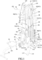
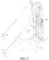
- the conventional exercise machine has a base seat 1, a first connecting pillar 8 that is perpendicular to and connected with the base seat 1, and a top beam 10 that is parallel to the base seat 1 and connected with the connecting pillar 8.
- the top beam 10 is connected to a first weight stack 3 via two first guiding posts 5 that are connected to the rear of the top beam 10.
- the top beam 10 includes a first fixed pulley 11 and a second fixed pulley 9 respectively mounted at a front and a rear of the top beam 10.
- the conventional exercise machine has a first steel cable 4 that has one end co-movably connected with a handle bar 12, and another end that is connected with the weight stack 3.
- the conventional exercise machine allows a user to perform weight training by pulling the mounting bar 12 and lifting the weight stack 3.
- the conventional exercise machine is only useful for weight training and is unsuitable for cardio training as the weight stack 3 is slow in responding to the user pulling the mounting bar 12. This is due to the inertia of the weight stack 3, which causes the weight stack 3 to have a delayed acceleration under gravity after it has reached its highest point in an upwards movement. Furthermore, friction between the weight stack 3 and the guiding posts 5, and between the steel cable 4 and the first and second fixed pulleys 11, 9 exacerbates the slow response. Therefore, the conventional exercise machine is unsuitable for aerobic exercises that require quick feedback and swift movements such as rowing, cross-training, or boxing.
- an object of the disclosure is to provide a fitness exercise apparatus that can alleviate at least one of the drawbacks of the prior art.
- the fitness exercise apparatus includes a main frame, a seat unit, a resistance unit, a transmission unit, and an operating unit.
- the main frame includes a base seat and a support unit that is connected to the base seat.
- the seat unit is mounted detachably on the base seat.
- the resistance unit includes a weight subunit that is mounted on the main frame, and an elastic subunit that is connected between the weight subunit and the main frame.
- the transmission unit includes a first fixed pulley set, two second fixed pulley sets, two third fixed pulley sets, a first movable pulley, a movable pulley set, two second movable pulleys, a first cable, two second cables, and a third cable.
- the first fixed pulley set is mounted on the support unit, and the two second fixed pulley sets are mounted on the support unit.
- the two third fixed pulley sets are mounted on the base seat, and the first movable pulley is disposed above the base seat and is proximate to the support unit.
- the movable pulley set is disposed at a side of the first movable pulley, and the two second movable pulleys are disposed respectively at opposite sides of the first movable pulley.
- the first cable wraps around the first fixed pulley set, the first movable pulley and the movable pulley set.
- the two second cables each wrapping around a respective one of the second movable pulleys and a respective one of the second fixed pulley sets.
- the third cable wraps around the third fixed pulley set and the movable pulley set, and is connected to the second movable pulleys.
- the operating unit includes at least one operating member that is connected to one of the first and second cables and pulling of the first cable drives the first movable pulley to move upwardly, thereby resulting in movement of the weight subunit against an elastic force of the elastic subunit.
- a pulling of the second cables drives the second movable pulleys to move upwardly, thereby pulling the first cable via the third cable and the movable pulley set, and eventually resulting in movement of the weight subunit against an elastic force of the elastic subunit.
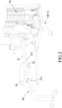
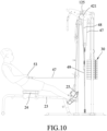
- an embodiment of a fitness exercise apparatus includes a main frame 10, a seat unit 20, a resistance unit 30, a transmission unit 40, and an operating unit 50.
- the main frame 10 includes a base seat 11 and a support unit 12 that is connected to the base seat 11.
- the base seat 11 includes two spaced-apart legs 111, a plurality of connecting rods 112 that are connected between the legs 111, and two retaining members 113.
- Each of the legs 111 of the base seat 11 has a base segment 114 and an inclined segment 115 that is transverse to the base segment 114, that has an inner end 116 connected to the base segment 114, and an outer end 117 opposite to the inner end 116.
- a distance between the inclined segments 115 of the legs 111 gradually increases from the inner ends 116 of the inclined segments 115 towards the outer ends 117 of the inclined segments 115.
- the retaining members 113 are half-round gutter shaped, are respectively connected fixedly to the inclined segment 115 of the legs 111.
- the support unit 12 of the main frame includes a rear frame member 121, a front frame member 122, a hanging member 123, two lower mounting rods 124, an upper mounting rod 125, two guide rods 126, and a support handle 127.
- the rear frame member 121 is inverted U-shaped and connected to the two legs 111 of the base seat 11.
- the front frame member 122 is connected between the rear frame member 121 and the base seat 10, and is inverted L-shaped.
- the hanging member 123 is mounted on top of the front frame member 122.
- the two lower mounting rods 124 are connected respectively to opposite lateral sides of the front frame member 122 (see Figure 12 ).
- the upper mounting rod 125 is mounted on the hanging member 123.
- the two guide rods 126 extend upwardly from the base seat 11 to the rear frame member 121, and the support handle 127 is mounted on the front frame member 122.
- the seat unit 20 is mounted detachably on the base seat 11, and includes an inner leg member 21, and outer leg member 22, a guide rail 23, a seat member 24, two foot rests 25, and a latch unit 26.
- the inner leg member 21 is coupled removably to the retaining members 113.
- the guide rail 23 is connected between the inner leg member 21 and the outer leg member 22.
- the seat member 24 is mounted on the guide rail 23, the foot rests 25 are secured to the inner leg member 21, and the latch unit 26 is mounted to the seat member 24.
- the inner leg member 21 includes a stationary tube 211, an inner leg rod 212, and an adjusting component 213.
- the stationary tube 211 is connected transversely to the guide rail 23.
- the inner leg rod 212 is inverted T-shaped, and has two arms coupled removably and respectively to the retaining members 113 of the base seat 11. Moreover, the inner leg rod 212 is connected telescopically to the stationary tube 211 and is formed with a plurality of adjusting holes 214. The adjusting component 213 is inserted transversely into the stationary tube 211 and engages a selected one of the adjusting holes 214.
- the seat member 24 is capable of sliding relative to the guide rail 23 or capable of being securely affixed to the guide rail 23 via the latch unit 26. More specifically, the guide rail 23 has a plurality of securing holes 231 arranged lengthwise.
- the latch unit 26 has a latch pin 262, an outer sleeve 261 that is sleeved over the latch pin 262 and that has a groove 266, and a spring 263 that is sleeved on the latch pin 262 and that is disposed between the latch pin 262 and the outer sleeve 261.
- the latch pin 262 has a latch end 264 that can engage a selected one of the securing holes 231 of the guide rail 23 to securely fix the seat member 24 to the guide rail 23.
- the latch unit 26 further has a pull knob 265 opposite to the latch end 264 of the latch pin 262.
- the spring 263 biases the latch end 264 of the latch pin 262 against the guide rail 23, so that the latch pin 262 can remain securely engaged to the selected one of the securing holes 231 of the guide rail 23 when the latch end 264 of the latch pin 262 engages that securing hole 231.
- the pull knob 265 is connected fixedly to the latch pin 262, and has an index portion 267 that is registered with the groove 266 of the latch pin 262. When the seat member 24 is securely fixed to the guide rail 23 via the latch unit 26, and the index portion 267 of the pull knob 265 engages the groove 266 of the latch pin 262.
- the pull knob 265 can then be pulled to disengage the index portion 267 from the groove 266, and the pulling back of the pull knob 265 disengages the latch end 264 of the latch pin 262 from the securing hole 231 of the guide rail 23.
- the pull knob 265 can be rotated 90 degrees so that the latch end 264 remains disengaged from the securing hole 231 by preventing the index portion 267 from engaging the groove 266 of the latch pin 262, thereby facilitating sliding movement of the seat member 24 relative to the guide rail 23.
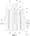
- the resistance unit 30 includes a weight subunit 31 that is mounted on the main frame 10, and an elastic subunit 32 that is connected between the weight subunit 31 and the main frame 10.
- the weight subunit 31 includes a connecting seat 311 that is slidable along the guide rods 126, an adjusting rod 312 that extends through the connecting seat 311, a plurality of weight plates 313 that are slidably sleeved on the guide rods 126 and the adjusting rod 312, and an adjusting pin 314 that is inserted removably into a selected one of the weight plates 313 and the adjusting rod 312.
- the adjusting rod 312 has a plurality of pin holes 315.
- the elastic subunit 32 includes two elastic sets 323 that are disposed respectively at opposite sides of the weight subunit 31.
- Each of the elastic sets 323 includes a plurality of elastic strips 324, each of said elastic strips 324 has opposite ends that are connected respectively to the connecting seat 311 and the base seat 11.
- the elastic subunit 32 further includes two upper hangers 321 that are mounted on the connecting seat 311 and that are disposed respectively on opposite sides of the two guide rods 126, and two lower hangers 322 that are mounted to the base seat 11 and that are disposed respectively on opposite sides of the two guide rods 126.
- Each of the elastic sets 323 is connected between a respective one of the upper hangers 321 and a respective one of the lower hangers 322.
- the two opposite ends of the elastic strips 324 are respectively connected to the respective one of the upper hangers 321 and the respective one of the lower hangers 322.
- the number of the elastic strips 324 of the two elastic sets 323 are the same.
- the transmission unit 40 includes a first fixed pulley set 41, two second fixed pulley sets 42, two third fixed pulley sets 43, a first movable pulley 44, a moveable pulley set 45, two second movable pulleys 46, a first cable 47, two second cables 48, and a third cable 49.
- the first fixed pulley set 41 and the two second fixed pulley sets 42 are mounted on the support unit 12; while the two third fixed pulley sets 43 are mounted on the base seat 11.
- the first movable pulley 44 is disposed above the base seat 11 and is proximate to the support unit 12.
- the movable pulley set 45 is disposed at a side of the first movable pulley 44, and the two second movable pulleys 46 are disposed respectively at opposite sides of the first movable pulley 44.
- the first cable 47 wraps around the first fixed pulley set 41, the first movable pulley 44 and the movable pulley set 45.
- the two second cables 48 each wrapping around a respective one of the second movable pulleys 46 and a respective one of the second fixed pulley sets 42.
- the third cable 49 wraps around the third fixed pulley set 43 and the movable pulley set 45, and is connected to the second movable pulleys 46.
- the first fixed pulley set 41 of the transmission unit 40 includes a plurality of first fixed pulleys 411 that are mounted to the front frame member 122, the rear frame member 121, and the hanging member 123.
- Each of the second fixed pulley sets 42 of the transmission unit 40 includes a plurality of second fixed pulleys 421 that are mounted to a respective one of the lower mounting rods 124 and a respective one of opposite lateral ends of the upper mounting rod 125.
- Each of the third fixed pulley set 43 includes a plurality of third fixed pulleys 431 mounted on the base seat 11.
- the movable pulley set 45 of the transmission unit 40 includes a block 451, an upper movable pulley 452 fixed on the block 451, and a lower movable pulley 453 fixed on the block 452 and disposed under the upper movable pulley 452.
- the first cable 47 also wraps around the upper movable pulley 452, and the third cable 49 wraps around the lower movable pulley 453.
- the operating unit 50 includes at least one operating member that is connected to one of the first and second cables 47, 48.
- the operating unit 50 includes a plurality of operating members that are configured as two hand grips 51, a long handlebar 52, or a short handlebar 53.
- the two hand grips 51 are respectively detachably connected to the second cables 48.
- the long handlebar 52 is detachably connected to a first end of the first cable 47
- the short handlebar 53 is detachably connected to a second end of the first cable 47.
- the inner leg member 21 is first coupled to the retaining members 113, and the seat member 24 may be selected, according to the type of training the user wishes to perform, to either slide against or be securely affixed to the guide rail 23 via the latch unit 26.
- the number of elastic strips 324 may also be selected according to the type of training the user wishes to engage in, and the two opposite ends of each elastic strip 324 are respectively connected to the upper hanger 321 and the lower hanger 322 on a same side of the two guide rods 126.
- the adjusting pin 314 (see Figure 5 ) is inserted into a selected one of the weight plates 313 and a corresponding pin hole 315 of the adjusting rod 312.
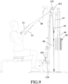
- the user may exert a pulling movement by pulling the long handlebar 52 downwards.
- the pulling of the first cable 47 drives the movable pulley 44 to move upwardly, thereby resulting in upward movement of the weight subunit 31 against an elastic force of the elastic subunit 32.
- the first fixed pulley set 41 and the upper movable pulley 452 guide the first cable 47, and second end of the first cable 47 is fixed by the front frame member 122 to prevent movement, so that when the when the long handlebar 52 is pulled by the user, the first movable pulley 44 and the weight subunit 31 will be moved upwards.
- the above setup allows the user to perform a wide grip lat pulldown exercise as shown in Figure 8 , where the user is shown seated facing the fitness exercise apparatus.
- the user may vary the resistance of the exercise by inserting the adjusting pin 314 in a different weight plate 313 via a corresponding pin hole 315 of the adjusting rod 312 and/or by changing the number and/or resistance of the elastic strips 324.
- the same set up also allows the user to perform a wide grip rear pulldown exercise (not shown in the Figures) by sitting in a reverse position with their back facing the fitness exercise apparatus.
- the advantages of the fitness exercise apparatus according to the disclosure is that the exercises may be performed aerobically as well as anaerobically.
- the weight blocks 313 of the weight subunit 31 are moved upwardly to a highest position and begins descending downwards the weight blocks 313 are accelerated by the force of gravity as wells as a restoring force of the elastic strips 324, which results in increased acceleration and speed of return that allows the user to perform quicker repetitions and exercises aerobically.
- the user is shown performing a chest pull exercise on the fitness exercise apparatus.
- the fitness exercise apparatus is set up by connecting the two hand grips 51 respectively to the first ends of the two second cables 48 with the second ends of the second cables 48 being fixed. The user may then perform a pulling motion on the two hand grips 51 which pulls the two second cables 48.
- the pulling of the second cables 48 drives the second movable pulleys 46 to move upwardly, thereby pulling the first cable 47 via the third cable 49 and the movable pulley set 45, and eventually resulting in upward movement of the weight subunit 31 and the first movable pulley 44 against the elastic force of the elastic subunit 32.
- a seated straight arm pulldown exercise may be performed from the same setup of the fitness exercise apparatus as described above.
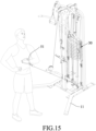
- a seated cable row exercise may be performed on the fitness exercise apparatus.
- the fitness exercise apparatus is set up by operating the latch unit 26 so that the seat member 24 is capable of sliding relative to the guide rail 23.
- the user is seated on the seat member 24 and has both feet planted on the foot rests 25.
- the short handlebar 53 which is connected to the second end of the first cable 47, is used in this exercise.
- the user pulls the short handlebar 53 while seated on the seat member 24 and sliding relative to the guide rail 23.
- the first end of the first cable 47 is fixed to prevent movement, so that resistance against the user's pull from the resistance unit 30 can be transferred via the first cable 47.
- the seated cable row exercise allows the user to effectively train the latissimus dorsi muscles and the trapezius muscles.
- the seat unit 20 may be detached from the main frame 10 to allow the user to perform a triceps push down exercise.
- the user is standing and uses the long handlebar 52 to pull down against the resistance of the resistance unit 30.
- the setup is similar to the wide grip lat pulldown exercise shown in Figure 8 and further details are omitted for the sake of brevity.
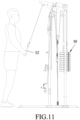
- the user is shown performing a standing low pulley bicep curl.
- the seat unit 20 is detached from the main frame 10 and the user stands in the middle of the spaced-apart legs 111 of the base seat 11.
- the two hand grips 51 are connected respectively to the second ends of the two second cables 48 with the first ends of the second cables 48 being fixed.
- the user exerts a pulling motion that pulls the second cables 48.
- the pulling of the second cables 48 will drive the second movable pulleys 46 to move upwardly, thereby pulling the first cable 47 via the third cable 49 and the movable pulley set 45, and eventually the weight subunit 31 and the first movable pulley 44 will be pulled upward.
- the resistance unit 30 provides resistance against the user's pulling motion.
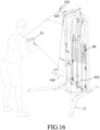
- the user is shown performing an alternating straight arm pulldown exercise.
- the fitness exercise apparatus is set up by detaching the seat unit 24 from the main frame 10, and then respectively connecting the two hand grips 51 to the first ends of the two second cables 48 with the second ends of the second cables 48 being fixed.
- the user performs a pulling motion with the two hand grips 51 by pulling the two second cables 48.
- the pulling of the second cables 48 will drive the second movable pulleys 46 to move upwardly, thereby pulling the first cable 47 via the third cable 49 and the moveable pulley set 45, and eventually resulting in upward movement of the weight subunit 31 and the first movable pulley 44 against the elastic force of the elastic subunit 32.
- a standing straight arm pulldown exercise may be performed from the same setup of the fitness exercise apparatus.
- the user is shown performing a cross body bicep curl exercise.
- the user stands sideways relative to the main frame 10 of the fitness exercise apparatus and performs a pulling motion using only a single hand grip 51 that is connected to the second end of one of the second cables 48.
- the user is shown performing a standing high and low cable crossover exercise, where the user pulls the two hand grips 51 from a higher angle and a lower angle, to crossover at chest height.
- one of the two hand grips 51 is connected to the first end of one of the second cables 48, and the other one of the two hand grips 51 is connected to the second end of the other one of the second cables 48.
- the user is showing performing an alternating leg drop exercise.
- the fitness exercise apparatus is setup the same as for the chest pull exercise, and the user uses the hand grips 51 as foot straps.
- a conventional rowing machine display and sensor 61 is installed on the seat unit 20
- a phone holder 62 is installed on the support unit 12
- sensors 521, 531 are installed respectively on the long handlebar 52 and the short handlebar 53.
- These instruments allow the fitness exercise apparatus to display various exercise data such as laps/repetitions, speed, calorie expenditure, and heart rate so that the user may monitor their training progress and measure their progress quantitatively. This may increase user motivation and incentivize the user to accomplish their fitness goals.
- the user may monitor their calorie expenditure and their heart rate from the conventional rowing machine display and sensor 61.
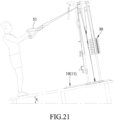
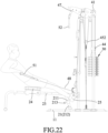
- the user is shown performing a cable glute kickback exercise where the support handle 127 may be used for support and the operating member may be an ankle strap.
- the fitness exercise apparatus has the functions of both cardio and strength training exercise machines.
- the structure is simple, and the manufacture process may be streamlined.
- the fitness exercise apparatus allows users to quickly reach their strength training as well as cardio fitness goals.
Landscapes
- Health & Medical Sciences (AREA)
- General Health & Medical Sciences (AREA)
- Physical Education & Sports Medicine (AREA)
- Life Sciences & Earth Sciences (AREA)
- Biophysics (AREA)
- Orthopedic Medicine & Surgery (AREA)
- Rehabilitation Tools (AREA)
Claims (10)
- Eine Fitnesstrainingsvorrichtung, die folgende Merkmale umfasst:einen Hauptrahmen (10), der einen Basissitz (11) und eine Stützeinheit (12) umfasst, die mit dem Basissitz (11) verbunden ist,;eine Sitzeinheit (20), die abnehmbar an dem Basissitz (11) befestigt ist;eine Übertragungseinheit (40), die folgende Merkmale umfasst:einen ersten fixierten Rollensatz (41), der an der Stützeinheit (12) befestigt ist,zwei zweite fixierte Rollensätze (42), die an der Stützeinheit (12) befestigt sind,zwei dritte fixierte Rollensätze (43), die an dem Basissitz (11) befestigt sind,eine erste bewegliche Rolle (44), die über dem Basissitz (11) angeordnet ist und die sich in der Nähe der Stützeinheit (12) befindet,einen beweglichen Rollensatz (45), der an einer Seite der ersten beweglichen Rolle (44) angeordnet ist,zwei zweite bewegliche Rollen (46), die jeweils an gegenüberliegenden Seiten der ersten beweglichen Rolle (44) angeordnet sind,ein erstes Kabel (47), das um den ersten fixierten Rollensatz (41), die erste bewegliche Rolle (44) und den beweglichen Rollensatz (45) gewickelt ist,zwei zweite Kabel (48), die jeweils um eine jeweilige der zweiten beweglichen Rollen (46) und einen jeweiligen der zweiten fixierten Rollensätze (42) gewickelt sind, undein drittes Kabel (49), das um den dritten fixierten Rollensatz (43) und den beweglichen Rollensatz (45) gewickelt ist und das mit den zweiten beweglichen Rollen (46) verbunden ist; undeine Betätigungseinheit (50), die zumindest ein Betätigungsbauglied (51, 52, 53) umfasst, das mit einem des ersten und zweiten Kabels (47, 48) verbunden ist;dadurch gekennzeichnet, dass die Fitnesstrainingsvorrichtung ferner folgende Merkmale umfasst:eine Widerstandseinheit (30), die eine Gewichtsuntereinheit (31), die an dem Hauptrahmen (10) befestigt ist, und eine elastische Untereinheit (32), umfasst die zwischen der Gewichtsuntereinheit (31) und dem Hauptrahmen (10) verbunden ist,;wobei das Ziehen des ersten Kabels (47) die erste bewegliche Rolle (44) antreibt, sich nach oben zu bewegen, was zu einer Bewegung der Gewichtsuntereinheit (31) gegen eine elastische Kraft der elastischen Untereinheit (32) führt; undwobei das Ziehen der zweiten Kabel (48) die zweiten beweglichen Rollen (46) antreibt, sich nach oben zu bewegen, wodurch das erste Kabel (47) über das dritte Kabel (49) und den beweglichen Rollensatz (45) gezogen wird, was schließlich zu einer Bewegung der Gewichtsuntereinheit (31) gegen eine elastische Kraft der elastischen Untereinheit (32) führt.
- Die Fitnesstrainingsvorrichtung gemäß Anspruch 1, dadurch gekennzeichnet, dass:die Stützeinheit (12) des Hauptrahmens (10) ein hinteres Rahmenbauglied (121), das eine umgekehrte U-Form aufweist, ein vorderes Rahmenbauglied (122), das zwischen dem hinteren Rahmenbauglied (121) und dem Basissitz (10) verbunden ist und das eine umgekehrte L-Form aufweist, und ein Hängebauglied (123) umfasst, das auf dem vorderen Rahmenbauglied (122) befestigt ist; undder erste fixierte Rollensatz (41) der Übertragungseinheit (40) eine Mehrzahl von ersten fixierten Rollen (411) umfasst, die an dem vorderen Rahmenbauglied (122), dem hinteren Rahmenbauglied (121) und dem Hängebauglied (123) befestigt sind.
- Die Fitnesstrainingsvorrichtung gemäß Anspruch 2, dadurch gekennzeichnet, dass:die Stützeinheit (12) des Hauptrahmens (10) ferner zwei untere Befestigungsstangen (124), die jeweils mit gegenüberliegenden lateralen Seiten des vorderen Rahmenbauglieds (122) verbunden sind, und eine obere Befestigungsstange (125) umfasst, die an dem Hängebauglied (123) befestigt ist; undjeder der zweiten fixierten Rollensätze (42) der Übertragungseinheit (40) eine Mehrzahl von zweiten fixierten Rollen (421) umfasst, die an einer jeweiligen der unteren Befestigungsstangen (124) und einem jeweiligen der gegenüberliegenden lateralen Enden der oberen Befestigungsstange (125) befestigt sind.
- Die Fitnesstrainingsvorrichtung gemäß Anspruch 3, dadurch gekennzeichnet, dass jeder der dritten fixierten Rollensätze (43) der Übertragungseinheit (40) eine Mehrzahl von dritten fixierten Rollen (431) umfasst, die an dem Basissitz (11) befestigt sind.
- Die Fitnesstrainingsvorrichtung gemäß einem der Ansprüche 1 und 3, dadurch gekennzeichnet, dass:der bewegliche Rollensatz (45) der Übertragungseinheit (40) einen Block (451), eine obere bewegliche Rolle (452), die an dem Block (451) fixiert ist, und eine untere bewegliche Rolle (453) umfasst, die an dem Block (452) fixiert ist und unter der oberen beweglichen Rolle (452) angeordnet ist;das erste Kabel (47) um die obere bewegliche Rolle (452) gewickelt ist; unddas dritte Kabel (49) um die untere bewegliche Rolle (453) gewickelt ist.
- Die Fitnesstrainingsvorrichtung gemäß einem der Ansprüche 1 bis 5, dadurch gekennzeichnet, dass:die Stützeinheit (12) zwei Führungsstangen (126) umfasst, die sich von dem Basissitz (11) nach oben erstrecken;die Gewichtsuntereinheit (31) der Widerstandseinheit (30) folgende Merkmale umfasst:einen Verbindungssitz (311), der entlang der Führungsstangen (126) verschiebbar ist,eine Einstellstange (312), die sich durch den Verbindungssitz (311) erstreckt,eine Mehrzahl von Gewichtsplatten (313), die verschiebbar auf die Führungsstangen (126) und die Einstellstange (312) geschoben sind, undeinen Einstellstift (314), der entfernbar in eine ausgewählte der Gewichtsplatten (313) und der Einstellstange (312) eingefügt ist;die elastische Untereinheit (32) zwei elastische Sätze (323) umfasst, die jeweils an gegenüberliegenden Seiten der Gewichtsuntereinheit (31) angeordnet sind;jeder der elastischen Sätze (323) eine Mehrzahl von elastischen Streifen (324) umfasst, wobei jeder der elastischen Streifen (324) gegenüberliegende Enden aufweist, die mit dem Verbindungssitz (311) beziehungsweise dem Basissitz (11) verbunden sind; unddie Anzahl der elastischen Streifen (324) der zwei elastischen Sätze (323) gleich ist.
- Die Fitnesstrainingsvorrichtung gemäß Anspruch 6, dadurch gekennzeichnet, dass die Spezifikationen der elastischen Streifen (324) der elastischen Sätze (323) identisch sind.
- Die Fitnesstrainingsvorrichtung gemäß einem der Ansprüche 1 bis 7, dadurch gekennzeichnet, dass:der Basissitz (11) zwei beabstandete Beine (111), eine Mehrzahl von Verbindungsstangen (112), die zwischen den Beinen (111) verbunden sind, und zwei Haltebauglieder (113) umfasst, die jeweils fest mit den Beinen (111) verbunden sind; unddie Sitzeinheit (20) ein inneres Beinbauglied (21), das entfernbar mit den Haltebaugliedern (113) gekoppelt ist, ein äußeres Beinbauglied (22), eine Führungsschiene (23), die zwischen dem inneren Beinbauglied (21) und dem äußeren Beinbauglied (22) verbunden ist, und ein Sitzbauglied (24) umfasst, das an der Führungsschiene (23) befestigt ist.
- Die Fitnesstrainingsvorrichtung gemäß Anspruch 8, dadurch gekennzeichnet, dass:das innere Beinbauglied (21) der Sitzeinheit (20) ein stationäres Rohr (211), das quer mit der Führungsschiene (23) verbunden ist, eine innere Beinstange (212), die teleskopisch mit dem stationären Rohr (211) verbunden ist und die mit einer Mehrzahl von Einstelllöchern (214) ausgebildet ist, und eine Einstellkomponente (213) umfasst, die quer in das stationäre Rohr (211) eingefügt ist und die in ein ausgewähltes der Einstelllöcher (214) eingreift; unddie innere Beinstange (212) eine umgekehrte T-Form aufweist und zwei Arme aufweist, die entfernbar und jeweils mit den Haltebaugliedern (113) des Basissitzes (11) gekoppelt sind.
- Die Fitnesstrainingsvorrichtung gemäß Anspruch 8, dadurch gekennzeichnet, dass jedes der Beine (111) des Basissitzes (11) folgende Merkmale aufweist:ein Basissegment (114); undein geneigtes Segment (115), das quer zu dem Basissegment (114) ist, das ein inneres Ende (116), das mit dem Basissegment (114) verbunden ist, und ein äußeres Ende (117) aufweist, das dem inneren Ende (116) gegenüberliegt, wobei ein Abstand zwischen den geneigten Segmenten (115) der Beine (111) von den inneren Enden (116) der geneigten Segmente (115) zu den äußeren Enden (117) der geneigten Segmente (115) allmählich zunimmt.
Priority Applications (2)
| Application Number | Priority Date | Filing Date | Title |
|---|---|---|---|
| EP22203010.8A EP4356982B1 (de) | 2022-10-21 | 2022-10-21 | Fitnessübungsgerät |
| ES22203010T ES3000070T3 (en) | 2022-10-21 | 2022-10-21 | Fitness exercise apparatus |
Applications Claiming Priority (1)
| Application Number | Priority Date | Filing Date | Title |
|---|---|---|---|
| EP22203010.8A EP4356982B1 (de) | 2022-10-21 | 2022-10-21 | Fitnessübungsgerät |
Publications (3)
| Publication Number | Publication Date |
|---|---|
| EP4356982A1 EP4356982A1 (de) | 2024-04-24 |
| EP4356982C0 EP4356982C0 (de) | 2024-11-20 |
| EP4356982B1 true EP4356982B1 (de) | 2024-11-20 |
Family
ID=83903062
Family Applications (1)
| Application Number | Title | Priority Date | Filing Date |
|---|---|---|---|
| EP22203010.8A Active EP4356982B1 (de) | 2022-10-21 | 2022-10-21 | Fitnessübungsgerät |
Country Status (2)
| Country | Link |
|---|---|
| EP (1) | EP4356982B1 (de) |
| ES (1) | ES3000070T3 (de) |
Family Cites Families (4)
| Publication number | Priority date | Publication date | Assignee | Title |
|---|---|---|---|---|
| US20060189457A1 (en) * | 2005-01-14 | 2006-08-24 | Barry Ripley | Exercise device |
| ITBO20080126A1 (it) * | 2008-02-27 | 2009-08-28 | Technogym Spa | Macchina ginnica. |
| CN205683489U (zh) | 2016-06-13 | 2016-11-16 | 巢湖学院 | 一种新型多功能室内健身机 |
| US11338168B2 (en) * | 2020-05-20 | 2022-05-24 | Yangzhou Jiuyi Hardware & Machinery Co., Ltd. | Fitness exercise apparatus |
-
2022
- 2022-10-21 EP EP22203010.8A patent/EP4356982B1/de active Active
- 2022-10-21 ES ES22203010T patent/ES3000070T3/es active Active
Also Published As
| Publication number | Publication date |
|---|---|
| EP4356982C0 (de) | 2024-11-20 |
| EP4356982A1 (de) | 2024-04-24 |
| ES3000070T3 (en) | 2025-02-27 |
Similar Documents
| Publication | Publication Date | Title |
|---|---|---|
| US12172044B2 (en) | Fitness exercise apparatus | |
| US8926480B2 (en) | Three-point adjustment multi-purpose exercise machine | |
| US4836535A (en) | Upper body building machine | |
| US7927262B2 (en) | Compact multi-function exercise apparatus | |
| US20100035729A1 (en) | Multimotion exercise apparatus and method | |
| US7537552B2 (en) | Exercise device with centrally mounted resistance rod and automatic weight selector apparatus | |
| US11338168B2 (en) | Fitness exercise apparatus | |
| US20220176194A1 (en) | Exercise system and method | |
| US11712598B2 (en) | Fitness exercise apparatus | |
| US20230118879A1 (en) | Fitness exercise apparatus | |
| US12036434B2 (en) | Adjustable exercise equipment | |
| US12324944B2 (en) | Exercise machine | |
| US12017106B2 (en) | Fitness exercise apparatus | |
| US7104938B1 (en) | Holistic exercise device | |
| EP4356982B1 (de) | Fitnessübungsgerät | |
| US7503881B2 (en) | Exercise apparatus with weight stacks and elastic bands | |
| EP4356983B1 (de) | Fitnessübungsgerät | |
| CN214388676U (zh) | 一种体育训练背肌训练器 | |
| EP4166203A1 (de) | Fitnessübungsvorrichtung | |
| CN211327999U (zh) | 一种蹬杆可调节的普拉提锻炼器 | |
| CN219440592U (zh) | 一种用于体育训练的臂力训练装置 | |
| CN221771414U (zh) | 一种组合式体育健身器材 | |
| EP4166202A1 (de) | Fitnessübungsvorrichtung | |
| CN114377356A (zh) | 一种多功能健身器材 | |
| CN119015668A (zh) | 一种多功能健身器械 |
Legal Events
| Date | Code | Title | Description |
|---|---|---|---|
| PUAI | Public reference made under article 153(3) epc to a published international application that has entered the european phase |
Free format text: ORIGINAL CODE: 0009012 |
|
| STAA | Information on the status of an ep patent application or granted ep patent |
Free format text: STATUS: REQUEST FOR EXAMINATION WAS MADE |
|
| 17P | Request for examination filed |
Effective date: 20230705 |
|
| AK | Designated contracting states |
Kind code of ref document: A1 Designated state(s): AL AT BE BG CH CY CZ DE DK EE ES FI FR GB GR HR HU IE IS IT LI LT LU LV MC ME MK MT NL NO PL PT RO RS SE SI SK SM TR |
|
| GRAP | Despatch of communication of intention to grant a patent |
Free format text: ORIGINAL CODE: EPIDOSNIGR1 |
|
| GRAP | Despatch of communication of intention to grant a patent |
Free format text: ORIGINAL CODE: EPIDOSNIGR1 |
|
| STAA | Information on the status of an ep patent application or granted ep patent |
Free format text: STATUS: GRANT OF PATENT IS INTENDED |
|
| INTG | Intention to grant announced |
Effective date: 20240614 |
|
| GRAS | Grant fee paid |
Free format text: ORIGINAL CODE: EPIDOSNIGR3 |
|
| GRAA | (expected) grant |
Free format text: ORIGINAL CODE: 0009210 |
|
| STAA | Information on the status of an ep patent application or granted ep patent |
Free format text: STATUS: THE PATENT HAS BEEN GRANTED |
|
| AK | Designated contracting states |
Kind code of ref document: B1 Designated state(s): AL AT BE BG CH CY CZ DE DK EE ES FI FR GB GR HR HU IE IS IT LI LT LU LV MC ME MK MT NL NO PL PT RO RS SE SI SK SM TR |
|
| REG | Reference to a national code |
Ref country code: GB Ref legal event code: FG4D |
|
| REG | Reference to a national code |
Ref country code: CH Ref legal event code: EP |
|
| REG | Reference to a national code |
Ref country code: DE Ref legal event code: R096 Ref document number: 602022007896 Country of ref document: DE |
|
| REG | Reference to a national code |
Ref country code: IE Ref legal event code: FG4D |
|
| U01 | Request for unitary effect filed |
Effective date: 20241212 |
|
| U07 | Unitary effect registered |
Designated state(s): AT BE BG DE DK EE FI FR IT LT LU LV MT NL PT RO SE SI Effective date: 20241223 |
|
| REG | Reference to a national code |
Ref country code: ES Ref legal event code: FG2A Ref document number: 3000070 Country of ref document: ES Kind code of ref document: T3 Effective date: 20250227 |
|
| PG25 | Lapsed in a contracting state [announced via postgrant information from national office to epo] |
Ref country code: HR Free format text: LAPSE BECAUSE OF FAILURE TO SUBMIT A TRANSLATION OF THE DESCRIPTION OR TO PAY THE FEE WITHIN THE PRESCRIBED TIME-LIMIT Effective date: 20241120 Ref country code: IS Free format text: LAPSE BECAUSE OF FAILURE TO SUBMIT A TRANSLATION OF THE DESCRIPTION OR TO PAY THE FEE WITHIN THE PRESCRIBED TIME-LIMIT Effective date: 20250320 |
|
| PG25 | Lapsed in a contracting state [announced via postgrant information from national office to epo] |
Ref country code: NO Free format text: LAPSE BECAUSE OF FAILURE TO SUBMIT A TRANSLATION OF THE DESCRIPTION OR TO PAY THE FEE WITHIN THE PRESCRIBED TIME-LIMIT Effective date: 20250220 |
|
| PG25 | Lapsed in a contracting state [announced via postgrant information from national office to epo] |
Ref country code: GR Free format text: LAPSE BECAUSE OF FAILURE TO SUBMIT A TRANSLATION OF THE DESCRIPTION OR TO PAY THE FEE WITHIN THE PRESCRIBED TIME-LIMIT Effective date: 20250221 |
|
| PG25 | Lapsed in a contracting state [announced via postgrant information from national office to epo] |
Ref country code: PL Free format text: LAPSE BECAUSE OF FAILURE TO SUBMIT A TRANSLATION OF THE DESCRIPTION OR TO PAY THE FEE WITHIN THE PRESCRIBED TIME-LIMIT Effective date: 20241120 |
|
| PG25 | Lapsed in a contracting state [announced via postgrant information from national office to epo] |
Ref country code: RS Free format text: LAPSE BECAUSE OF FAILURE TO SUBMIT A TRANSLATION OF THE DESCRIPTION OR TO PAY THE FEE WITHIN THE PRESCRIBED TIME-LIMIT Effective date: 20250220 |
|
| PG25 | Lapsed in a contracting state [announced via postgrant information from national office to epo] |
Ref country code: SM Free format text: LAPSE BECAUSE OF FAILURE TO SUBMIT A TRANSLATION OF THE DESCRIPTION OR TO PAY THE FEE WITHIN THE PRESCRIBED TIME-LIMIT Effective date: 20241120 |
|
| PG25 | Lapsed in a contracting state [announced via postgrant information from national office to epo] |
Ref country code: SK Free format text: LAPSE BECAUSE OF FAILURE TO SUBMIT A TRANSLATION OF THE DESCRIPTION OR TO PAY THE FEE WITHIN THE PRESCRIBED TIME-LIMIT Effective date: 20241120 |
|
| PG25 | Lapsed in a contracting state [announced via postgrant information from national office to epo] |
Ref country code: CZ Free format text: LAPSE BECAUSE OF FAILURE TO SUBMIT A TRANSLATION OF THE DESCRIPTION OR TO PAY THE FEE WITHIN THE PRESCRIBED TIME-LIMIT Effective date: 20241120 |
|
| U20 | Renewal fee for the european patent with unitary effect paid |
Year of fee payment: 4 Effective date: 20250811 |
|
| PLBE | No opposition filed within time limit |
Free format text: ORIGINAL CODE: 0009261 |
|
| STAA | Information on the status of an ep patent application or granted ep patent |
Free format text: STATUS: NO OPPOSITION FILED WITHIN TIME LIMIT |
|
| 26N | No opposition filed |
Effective date: 20250821 |
|
| PGFP | Annual fee paid to national office [announced via postgrant information from national office to epo] |
Ref country code: ES Payment date: 20251118 Year of fee payment: 4 |