EP4356978A1 - Hood assembly, method for assembling hood assembly and fire suppression system comprising hood assembly - Google Patents
Hood assembly, method for assembling hood assembly and fire suppression system comprising hood assembly Download PDFInfo
- Publication number
- EP4356978A1 EP4356978A1 EP23204196.2A EP23204196A EP4356978A1 EP 4356978 A1 EP4356978 A1 EP 4356978A1 EP 23204196 A EP23204196 A EP 23204196A EP 4356978 A1 EP4356978 A1 EP 4356978A1
- Authority
- EP
- European Patent Office
- Prior art keywords
- detection line
- fire detection
- wall
- hood assembly
- restricting element
- Prior art date
- Legal status (The legal status is an assumption and is not a legal conclusion. Google has not performed a legal analysis and makes no representation as to the accuracy of the status listed.)
- Pending
Links
Images


Classifications
-
- A—HUMAN NECESSITIES
- A62—LIFE-SAVING; FIRE-FIGHTING
- A62C—FIRE-FIGHTING
- A62C3/00—Fire prevention, containment or extinguishing specially adapted for particular objects or places
- A62C3/006—Fire prevention, containment or extinguishing specially adapted for particular objects or places for kitchens or stoves
-
- A—HUMAN NECESSITIES
- A62—LIFE-SAVING; FIRE-FIGHTING
- A62C—FIRE-FIGHTING
- A62C37/00—Control of fire-fighting equipment
- A62C37/36—Control of fire-fighting equipment an actuating signal being generated by a sensor separate from an outlet device
- A62C37/38—Control of fire-fighting equipment an actuating signal being generated by a sensor separate from an outlet device by both sensor and actuator, e.g. valve, being in the danger zone
- A62C37/42—Control of fire-fighting equipment an actuating signal being generated by a sensor separate from an outlet device by both sensor and actuator, e.g. valve, being in the danger zone with mechanical connection between sensor and actuator, e.g. rods, levers
Definitions
- This invention relates to the field of fire suppression systems, and more particularly, to a hood assembly of a fire suppression system.
- Fire suppression systems for industrial and commercial applications may include mechanical fire detection lines, which may include sensors to detect fires.
- the mechanical fire detection lines further include one or more tensioned lines that couple the sensors together. Once a fire is detected by any sensor, the sensor breaks, and the tensioned lines that were previously held under tension are now lax. This loss in tension may be used as a control signal to activate a control box to deploy countermeasures to limit the fire.
- mechanical fire detection lines are installed onsite.
- the mechanical fire detection lines are installed in a hood of commercial applications such as kitchens.
- installations of such mechanical fire detection lines may require modifications to be made to either the hoods, or the mechanical fire detection lines. As a result, the onsite installation process may be laborious and a potential for errors may also increase.
- a hood assembly including a housing having first and second walls arranged opposite to each other, the first and second walls being vertically oriented with respect to a floor on which the hood assembly is placed.
- the hood assembly further includes a mechanical fire detection line configured to detect presence of a fire within the housing.
- the mechanical fire detection line is disposed between the first and second walls, and extends beyond the second wall.
- the hood assembly further includes a restricting element disposed on the second wall, such that the mechanical fire detection line extends beyond the second wall of the hood assembly by passing through the restricting element.
- the restricting element is adapted to allow movement of the mechanical fire detection line along a first direction, and restrict movement of the mechanical fire detection line along a second direction opposite to the first direction.
- the first direction is along a length of the mechanical fire detection line towards the second wall.
- the second direction is along the length of the mechanical fire detection line towards the first wall.
- the second wall includes a through hole through which the mechanical fire detection line passes.
- the restricting element includes a through hole.
- the restricting element is disposed on the second wall, such that the through hole of the restricting element is coaxial with the through hole on the second wall.
- the mechanical fire detection line further passes through the through hole on the restricting element.
- the second wall includes a recess.
- the second wall includes a through hole at the recess.
- the restricting element is disposed on the second wall at the recess.
- the mechanical fire detection line further includes an output.
- the mechanical fire detection line terminates at the output after it extends beyond the second wall of the hood assembly.
- the restricting element includes a locking mechanism.
- actuating the locking mechanism causes the restricting element to restrict movement of the mechanical fire detection line along the second direction.
- a method for assembling a hood assembly including providing a housing having first and second walls arranged opposite to each other. The first and second walls are vertically oriented with respect to a floor on which the hood assembly is placed. The method further includes providing a mechanical fire detection line configured to detect presence of a fire within the housing. The mechanical fire detection line is disposed between the first and second walls, and extends beyond the second wall. The method further includes providing a restricting element disposed on the second wall, such that the mechanical fire detection line extends beyond the second wall of the hood assembly by passing through the restricting element. The restricting element is adapted to allow movement of the mechanical fire detection line along a first direction, and restrict movement of the mechanical fire detection line along a second direction opposite to the first direction.
- the first direction is along a length of the mechanical fire detection line towards the second wall.
- the second direction is along the length of the mechanical fire detection line towards the first wall.
- the method further includes providing a through hole on the second wall through which the mechanical fire detection line passes.
- the method further includes providing a through hole on the restricting element.
- the restricting element is disposed on the second wall such that the through hold of the restricting element is coaxial with the through hole on the second wall.
- the mechanical fire detection line further passes through the through hole on the restricting element.
- the method further includes providing a recess on the second wall.
- the second wall includes a through hole at the recess.
- the restricting element is disposed on the second wall at the recess.
- the method further includes providing the mechanical fire detection line with an output.
- the mechanical fire detection line terminates at the output after it extends beyond the second wall of the hood assembly.
- the method further includes providing the restricting element with a locking mechanism.
- actuating the locking mechanism causes the restricting element to restrict movement of the mechanical fire detection line along the second direction.
- a fire suppression system including a hood assembly.
- the hood assembly includes a housing having first and second walls arranged opposite to each other, the first and second walls being vertically oriented with respect to a floor on which the hood assembly is placed.
- the hood assembly further includes a mechanical fire detection line configured to detect presence of a fire within the housing.
- the mechanical fire detection line is disposed between the first and second walls, and extends beyond the second wall.
- the hood assembly further includes a restricting element disposed on the second wall, such that the mechanical fire detection line extends beyond the second wall of the hood assembly by passing through the restricting element.
- the restricting element is adapted to allow movement of the mechanical fire detection line along a first direction, and restrict movement of the mechanical fire detection line along a second direction opposite to the first direction.
- the hood assembly described in the third aspect of the invention may comprise any of the features of the hood assembly according to the first aspect of the invention.
- the fire suppression system 100 may be used in industrial and commercial applications.
- the fire suppression system 100 is one used in a commercial cooking application 102.
- the fire suppression system 100 includes a mechanical fire detection line 104 disposed within a hood 106 of the commercial cooking application 102.
- the mechanical fire detection line 104 may include one or more sensors 108 that are linked together via a tensioned line 110. When a fire may break out, the heat of the fire may cause one or more sensors 108 to break, thereby causing a drop in a tension of the tensioned line 110.
- This decrease in the tension of the tensioned line 110 may be used as a control signal to operate a control box 120.
- the control box 120 may then deploy countermeasures to suppress the fire that broke out.
- the countermeasures may include dispensing a fire suppression agent that is stored in a cannister 122.
- an assembly or installation of the mechanical fire detection line 104 in the hood 106 of the commercial cooking application 102 occurs on site.
- the hood 106 may include conduits for carrying the mechanical fire detection line 104.
- the installation of the mechanical fire detection line 104 and the subsequent tensioning of the mechanical fire detection line 104 is generally accomplished onsite. As a result, the installation process is more laborious. Further, the chances of errors in installation may be higher, which may lead to a failure in an operation of the mechanical fire detection line 104, resulting in the fire suppression system performing sub-optimally.
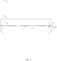
- FIG. 2 shows a schematic view of a hood assembly 200 including a mechanical fire detection line 220.
- the mechanical fire detection line 220 may be installed within the hood assembly 200 at a location where the hood assembly 200 is being assembled, such as at a fabrication facility, or an assembly facility.
- the hood assembly 200 may include a housing 201 including first and second walls 202, 204, which are adapted to be placed in a floor of a location where the hood assembly 200 is being installed.
- the first and second walls 202, 204 may be rigid structures, which are also adapted to provide structural support to the hood assembly 200.
- the hood assembly 200 further includes the mechanical fire detection line 220.
- the mechanical fire detection line 220 may be disposed between the first and second walls 202, 204 of the hood assembly 200.
- the mechanical fire detection line 220 includes an anchor 206 adapted to be rigidly coupled to any of the first and second walls 202, 204 of the hood assembly 200.
- the anchor 206 of the mechanical fire detection line 220 is rigidly coupled to the first wall 202.
- the mechanical fire detection line 220 extends from the any of the first and second walls 202, 204 towards another of the first and second walls 202, 204. In the illustrated embodiment of FIG. 2 , the mechanical fire detection line 220 extends from the first wall 202 towards the second wall 204. The mechanical fire detection line 220 further extends beyond the second wall 204, and passes through the second wall 204 to terminate at an output 208. Specifically, the mechanical fire detection line 220 passes through a through hole 210 provided on the second wall 204 and extends beyond the second wall 204 of the hood assembly 200 and terminates at the output 208. The output 208 may further be connected to other components, such as a trigger device 118, or the control box 120 (shown in FIG. 1 ). In some embodiments, the second wall 204 may include a recess 212. The recess 212 may include the through hole 210 through which the mechanical fire detection line 220 passes.
- the mechanical fire detection line 220 may further include components such as sensors 230, and tensioned lines 232.
- the tensioned lines 232 are coupled to the sensors 230 and hold the sensors 230 under a predefined tension. In the event of an undesired fire, the heat of the fire may break the sensor 230, which results in the tension in the tensioned lines 232 reducing. This reduced tension may be detectable at the output 208 of the mechanical fire detection line 220, and may be used as a control signal to actuate the control box to deploy suitable countermeasures.
- the mechanical fire detection line 220 may also include a tension indicating device (not shown) to determine that an optimum tension has been applied to the tensioned lines 232.
- the hood assembly 200 further includes a restricting element 240 disposed at the through hole 210 on the second wall 204.
- the restricting element 240 may be disposed such that it is coaxial with the through hole 210.
- the restricting element 240 further includes a through hole (not shown), such that the through holes of the restricting element 240 and the second wall 204 may be coaxial.
- the mechanical fire detection line 220 may further pass through the restricting element 240 before terminating at the output 208.
- the restricting element 240 is adapted to allow movement of the mechanical fire detection line 220 along a first direction, and limit movement of the mechanical fire detection line 220 along a second direction opposite to the first direction.
- the first direction may be along the mechanical fire detection line 220 and outwards of the second wall 204, towards the output 208.
- the restricting element 240 may allow the mechanical fire detection line 220 to be pulled from a side of the second wall 204. This may allow for any additional tensioning of the mechanical fire detection line 220.
- the restricting element 240 may limit movement of the mechanical fire detection line 220 towards the first wall 202. In other words, the restricting element 240 may limit the mechanical fire detection line 220 from losing tension.
- the restricting element 240 facilitates in maintaining the tension of the tensioned lines 232 within the hood assembly 200.
- the restricting element 240 may be made of a rigid material such as a metal, alloy, high density polymer, ceramic, etc. In some embodiments, the restricting element 240 may have a mechanism, such as a screw mechanism, that allows movement of the mechanical fire detection line 220 along the first direction, and limits the movement of the mechanical fire detection line 220 along the second direction.
- the restricting element 240 may have a width, such that after assembly of the restricting element 240, a surface of the restricting element 240 is flush with the second wall 204.
- FIG. 3 is a flow diagram for a method 300 for assembling the hood assembly 200.
- the method 300 includes providing the housing 201 having the first and second walls 202, 204 arranged opposite to each other.
- the first and second walls 202, 204 are vertically oriented with respect to a floor on which the hood assembly 200 is placed.
- the method 300 further includes providing the mechanical fire detection line 220 configured to detect presence of a fire within the housing 201.
- the mechanical fire detection line 220 is disposed between the first and second walls 202, 204, and extends beyond the second wall 204.
- the method 300 further includes providing the restricting element 240 disposed on the second wall 204, such that the mechanical fire detection line 220 extends beyond the second wall 204 of the hood assembly 200 by passing through the restricting element 240.
- the restricting element 240 is adapted to allow movement of the mechanical fire detection line 220 along a first direction, and restrict movement of the mechanical fire detection line 220 along a second direction opposite to the first direction.
- the hood assembly 200 provides a means to fully pre-install the mechanical fire detection line 220 within the hood assembly 200.
- the restricting element 240 allows the mechanical fire detection line 220 to be tensioned and limits any loss of tension that may occur in the mechanical fire detection line 220.
Landscapes
- Health & Medical Sciences (AREA)
- Public Health (AREA)
- Business, Economics & Management (AREA)
- Emergency Management (AREA)
- Fire Alarms (AREA)
- Fire-Detection Mechanisms (AREA)
Abstract
Description
- This invention relates to the field of fire suppression systems, and more particularly, to a hood assembly of a fire suppression system.
- Fire suppression systems for industrial and commercial applications may include mechanical fire detection lines, which may include sensors to detect fires. The mechanical fire detection lines further include one or more tensioned lines that couple the sensors together. Once a fire is detected by any sensor, the sensor breaks, and the tensioned lines that were previously held under tension are now lax. This loss in tension may be used as a control signal to activate a control box to deploy countermeasures to limit the fire. Typically, mechanical fire detection lines are installed onsite. Generally, the mechanical fire detection lines are installed in a hood of commercial applications such as kitchens. However, due to different manufacturers of hoods, and the many variations of hoods, installations of such mechanical fire detection lines may require modifications to be made to either the hoods, or the mechanical fire detection lines. As a result, the onsite installation process may be laborious and a potential for errors may also increase.
- According to a first aspect of the invention there is provided a hood assembly including a housing having first and second walls arranged opposite to each other, the first and second walls being vertically oriented with respect to a floor on which the hood assembly is placed. The hood assembly further includes a mechanical fire detection line configured to detect presence of a fire within the housing. The mechanical fire detection line is disposed between the first and second walls, and extends beyond the second wall. The hood assembly further includes a restricting element disposed on the second wall, such that the mechanical fire detection line extends beyond the second wall of the hood assembly by passing through the restricting element. The restricting element is adapted to allow movement of the mechanical fire detection line along a first direction, and restrict movement of the mechanical fire detection line along a second direction opposite to the first direction.
- Optionally, the first direction is along a length of the mechanical fire detection line towards the second wall. Optionally, the second direction is along the length of the mechanical fire detection line towards the first wall.
- Optionally, the second wall includes a through hole through which the mechanical fire detection line passes.
- Optionally, the restricting element includes a through hole. Optionally, the restricting element is disposed on the second wall, such that the through hole of the restricting element is coaxial with the through hole on the second wall. Optionally, the mechanical fire detection line further passes through the through hole on the restricting element.
- Optionally, the second wall includes a recess. Optionally, the second wall includes a through hole at the recess.
- Optionally, the restricting element is disposed on the second wall at the recess.
- Optionally, the mechanical fire detection line further includes an output. Optionally, the mechanical fire detection line terminates at the output after it extends beyond the second wall of the hood assembly.
- Optionally, the restricting element includes a locking mechanism. Optionally, actuating the locking mechanism causes the restricting element to restrict movement of the mechanical fire detection line along the second direction.
- According to a second aspect of the invention there is provided a method for assembling a hood assembly including providing a housing having first and second walls arranged opposite to each other. The first and second walls are vertically oriented with respect to a floor on which the hood assembly is placed. The method further includes providing a mechanical fire detection line configured to detect presence of a fire within the housing. The mechanical fire detection line is disposed between the first and second walls, and extends beyond the second wall. The method further includes providing a restricting element disposed on the second wall, such that the mechanical fire detection line extends beyond the second wall of the hood assembly by passing through the restricting element. The restricting element is adapted to allow movement of the mechanical fire detection line along a first direction, and restrict movement of the mechanical fire detection line along a second direction opposite to the first direction.
- Optionally, the first direction is along a length of the mechanical fire detection line towards the second wall. Optionally, the second direction is along the length of the mechanical fire detection line towards the first wall.
- Optionally, the method further includes providing a through hole on the second wall through which the mechanical fire detection line passes.
- Optionally, the method further includes providing a through hole on the restricting element. Optionally, the restricting element is disposed on the second wall such that the through hold of the restricting element is coaxial with the through hole on the second wall. Optionally, the mechanical fire detection line further passes through the through hole on the restricting element.
- Optionally, the method further includes providing a recess on the second wall. Optionally, the second wall includes a through hole at the recess.
- Optionally, the restricting element is disposed on the second wall at the recess.
- Optionally, the method further includes providing the mechanical fire detection line with an output. Optionally, the mechanical fire detection line terminates at the output after it extends beyond the second wall of the hood assembly.
- Optionally, the method further includes providing the restricting element with a locking mechanism. Optionally, actuating the locking mechanism causes the restricting element to restrict movement of the mechanical fire detection line along the second direction.
- According to a third aspect of the invention there is provided a fire suppression system including a hood assembly. The hood assembly includes a housing having first and second walls arranged opposite to each other, the first and second walls being vertically oriented with respect to a floor on which the hood assembly is placed. The hood assembly further includes a mechanical fire detection line configured to detect presence of a fire within the housing. The mechanical fire detection line is disposed between the first and second walls, and extends beyond the second wall. The hood assembly further includes a restricting element disposed on the second wall, such that the mechanical fire detection line extends beyond the second wall of the hood assembly by passing through the restricting element. The restricting element is adapted to allow movement of the mechanical fire detection line along a first direction, and restrict movement of the mechanical fire detection line along a second direction opposite to the first direction.
- The hood assembly described in the third aspect of the invention may comprise any of the features of the hood assembly according to the first aspect of the invention.
- The foregoing summary is illustrative only and is not intended to be in any way limiting. In addition to the illustrative aspects, embodiments, and features described above, further aspects, embodiments, features, and techniques of the invention will become more apparent from the following description taken in conjunction with the drawings.
- Certain exemplary embodiments will now be described in greater detail by way of example only and with reference to the accompanying drawings. The accompanying drawings are included to provide a further understanding of the subject disclosure of this invention and are incorporated in and constitute a part of this specification. The drawings illustrate exemplary embodiments of the subject disclosure and, together with the description, serve to explain the principles of the subject disclosure.
- In the drawings, similar components and/or features may have the same reference label. Further, various components of the same type may be distinguished by following the reference label with a second label that distinguishes among the similar components. If only the first reference label is used in the specification, the description is applicable to any one of the similar components having the same first reference label irrespective of the second reference label.
-
FIG. 1 is an exemplary schematic view of a fire suppression system diagram; -
FIG. 2 is a schematic view of a hood assembly for a fire suppression system comprising a mechanical fire detection line; and -
FIG. 3 is a flow diagram for a method to assemble a hood assembly for the fire suppression system comprising the mechanical fire detection line. - The following is a detailed description of embodiments of the disclosure depicted in the accompanying drawings. The embodiments are in such detail as to clearly communicate the disclosure. However, the amount of detail offered is not intended to limit the anticipated variations of embodiments; on the contrary, the intention is to cover all modifications, equivalents, and alternatives falling within the scope of the subject disclosure as defined by the appended claims.
- Various terms are used herein. To the extent a term used in a claim is not defined below, it should be given the broadest definition persons in the pertinent art have given that term as reflected in printed publications and issued patents at the time of filing.
- In the specification, reference may be made to the spatial relationships between various components and to the spatial orientation of various aspects of components as the devices are depicted in the attached drawings. However, as will be recognized by those skilled in the art after a complete reading of the subject disclosure, the components of this invention described herein may be positioned in any desired orientation. Thus, the use of terms such as "above," "below," "upper," "lower," "first", "second" or other like terms to describe a spatial relationship between various components or to describe the spatial orientation of aspects of such components should be understood to describe a relative relationship between the components or a spatial orientation of aspects of such components.
- Referring to
FIG. 1 , an exemplary schematic view of afire suppression system 100 is shown. Thefire suppression system 100 may be used in industrial and commercial applications. In the illustrated view ofFIG. 1 , thefire suppression system 100 is one used in acommercial cooking application 102. Thefire suppression system 100 includes a mechanicalfire detection line 104 disposed within ahood 106 of thecommercial cooking application 102. The mechanicalfire detection line 104 may include one ormore sensors 108 that are linked together via atensioned line 110. When a fire may break out, the heat of the fire may cause one ormore sensors 108 to break, thereby causing a drop in a tension of the tensionedline 110. This decrease in the tension of the tensionedline 110 may be used as a control signal to operate acontrol box 120. Thecontrol box 120 may then deploy countermeasures to suppress the fire that broke out. The countermeasures may include dispensing a fire suppression agent that is stored in acannister 122. - Generally, an assembly or installation of the mechanical
fire detection line 104 in thehood 106 of thecommercial cooking application 102 occurs on site. In some cases, thehood 106 may include conduits for carrying the mechanicalfire detection line 104. However, the installation of the mechanicalfire detection line 104 and the subsequent tensioning of the mechanicalfire detection line 104 is generally accomplished onsite. As a result, the installation process is more laborious. Further, the chances of errors in installation may be higher, which may lead to a failure in an operation of the mechanicalfire detection line 104, resulting in the fire suppression system performing sub-optimally. -
FIG. 2 shows a schematic view of ahood assembly 200 including a mechanicalfire detection line 220. The mechanicalfire detection line 220 may be installed within thehood assembly 200 at a location where thehood assembly 200 is being assembled, such as at a fabrication facility, or an assembly facility. Thehood assembly 200 may include ahousing 201 including first andsecond walls hood assembly 200 is being installed. The first andsecond walls hood assembly 200. Thehood assembly 200 further includes the mechanicalfire detection line 220. The mechanicalfire detection line 220 may be disposed between the first andsecond walls hood assembly 200. The mechanicalfire detection line 220 includes ananchor 206 adapted to be rigidly coupled to any of the first andsecond walls hood assembly 200. In the illustrated embodiment ofFIG. 2 , theanchor 206 of the mechanicalfire detection line 220 is rigidly coupled to thefirst wall 202. - The mechanical
fire detection line 220 extends from the any of the first andsecond walls second walls FIG. 2 , the mechanicalfire detection line 220 extends from thefirst wall 202 towards thesecond wall 204. The mechanicalfire detection line 220 further extends beyond thesecond wall 204, and passes through thesecond wall 204 to terminate at anoutput 208. Specifically, the mechanicalfire detection line 220 passes through a throughhole 210 provided on thesecond wall 204 and extends beyond thesecond wall 204 of thehood assembly 200 and terminates at theoutput 208. Theoutput 208 may further be connected to other components, such as atrigger device 118, or the control box 120 (shown inFIG. 1 ). In some embodiments, thesecond wall 204 may include arecess 212. Therecess 212 may include the throughhole 210 through which the mechanicalfire detection line 220 passes. - The mechanical
fire detection line 220 may further include components such assensors 230, and tensionedlines 232. The tensionedlines 232 are coupled to thesensors 230 and hold thesensors 230 under a predefined tension. In the event of an undesired fire, the heat of the fire may break thesensor 230, which results in the tension in the tensionedlines 232 reducing. This reduced tension may be detectable at theoutput 208 of the mechanicalfire detection line 220, and may be used as a control signal to actuate the control box to deploy suitable countermeasures. In some embodiments, the mechanicalfire detection line 220 may also include a tension indicating device (not shown) to determine that an optimum tension has been applied to the tensionedlines 232. - The
hood assembly 200 further includes a restrictingelement 240 disposed at the throughhole 210 on thesecond wall 204. The restrictingelement 240 may be disposed such that it is coaxial with the throughhole 210. The restrictingelement 240 further includes a through hole (not shown), such that the through holes of the restrictingelement 240 and thesecond wall 204 may be coaxial. In thehood assembly 200, the mechanicalfire detection line 220 may further pass through the restrictingelement 240 before terminating at theoutput 208. - The restricting
element 240 is adapted to allow movement of the mechanicalfire detection line 220 along a first direction, and limit movement of the mechanicalfire detection line 220 along a second direction opposite to the first direction. In some embodiments, the first direction may be along the mechanicalfire detection line 220 and outwards of thesecond wall 204, towards theoutput 208. In other words, the restrictingelement 240 may allow the mechanicalfire detection line 220 to be pulled from a side of thesecond wall 204. This may allow for any additional tensioning of the mechanicalfire detection line 220. Further, the restrictingelement 240 may limit movement of the mechanicalfire detection line 220 towards thefirst wall 202. In other words, the restrictingelement 240 may limit the mechanicalfire detection line 220 from losing tension. Thus, the restrictingelement 240 facilitates in maintaining the tension of the tensionedlines 232 within thehood assembly 200. - In some embodiments, the restricting
element 240 may be made of a rigid material such as a metal, alloy, high density polymer, ceramic, etc. In some embodiments, the restrictingelement 240 may have a mechanism, such as a screw mechanism, that allows movement of the mechanicalfire detection line 220 along the first direction, and limits the movement of the mechanicalfire detection line 220 along the second direction. - In some embodiments, in the case of the second wall having the
recess 212, the restrictingelement 240 may have a width, such that after assembly of the restrictingelement 240, a surface of the restrictingelement 240 is flush with thesecond wall 204. -
FIG. 3 is a flow diagram for amethod 300 for assembling thehood assembly 200. Atstep 302, themethod 300 includes providing thehousing 201 having the first andsecond walls second walls hood assembly 200 is placed. Atstep 304, themethod 300 further includes providing the mechanicalfire detection line 220 configured to detect presence of a fire within thehousing 201. The mechanicalfire detection line 220 is disposed between the first andsecond walls second wall 204. Atstep 306, themethod 300 further includes providing the restrictingelement 240 disposed on thesecond wall 204, such that the mechanicalfire detection line 220 extends beyond thesecond wall 204 of thehood assembly 200 by passing through the restrictingelement 240. The restrictingelement 240 is adapted to allow movement of the mechanicalfire detection line 220 along a first direction, and restrict movement of the mechanicalfire detection line 220 along a second direction opposite to the first direction. - Thus, the
hood assembly 200 provides a means to fully pre-install the mechanicalfire detection line 220 within thehood assembly 200. The restrictingelement 240 allows the mechanicalfire detection line 220 to be tensioned and limits any loss of tension that may occur in the mechanicalfire detection line 220. - While the invention has been described with reference to exemplary embodiments, it will be understood by those skilled in the art that various changes may be made and equivalents may be substituted for elements thereof without departing from the scope of the invention as defined by the appended claims. Modifications may be made to adopt a particular situation or material to the teachings of the invention without departing from the scope of the invention as defined by the appended claims. Therefore, it is intended that the invention not be limited to the particular embodiment disclosed, but that the invention includes all embodiments falling within the scope of the invention as defined by the appended claims.
- In interpreting the specification, all terms should be interpreted in the broadest possible manner consistent with the context. In particular, the terms "comprises" and "comprising" should be interpreted as referring to elements, components, or steps in a non-exclusive manner, indicating that the referenced elements, components, or steps may be present, or utilized, or combined with other elements, components, or steps that are not expressly referenced. Where the specification claims refer to at least one of something selected from the group consisting of A, B, C ....and N, the text should be interpreted as requiring only one element from the group, not A plus N, or B plus N, etc.
Claims (15)
- A hood assembly (200) comprising:a housing (201) having first and second walls (202, 204) arranged opposite to each other, the first and second walls being vertically oriented with respect to a floor on which the hood assembly is placed;a mechanical fire detection line (104; 220) configured to detect presence of a fire within the housing, the mechanical fire detection line disposed between the first and second walls, and extending beyond the second wall; anda restricting element (240) disposed on the second wall, such that the mechanical fire detection line extends beyond the second wall of the hood assembly by passing through the restricting element,wherein the restricting element is adapted to allow movement of the mechanical fire detection line along a first direction, and restrict movement of the mechanical fire detection line along a second direction opposite to the first direction.
- The hood assembly of claim 1, wherein the first direction is along a length of the mechanical fire detection line towards the second wall, and wherein the second direction is along the length of the mechanical fire detection line towards the first wall.
- The hood assembly of claims 1 or 2, wherein the second wall comprises a through hole (210) through which the mechanical fire detection line passes.
- The hood assembly of claim 3, wherein the restricting element comprises a through hole, wherein the restricting element is disposed on the second wall such that the through hole of the restricting element is coaxial with the through hole on the second wall, and wherein the mechanical fire detection line further passes through the through hole on the restricting element.
- The hood assembly of claims 3 or 4, wherein the second wall comprises a recess (212), wherein the through hole of the second wall is located at the recess, and optionally wherein the restricting element is disposed at the recess.
- The hood assembly of any of the preceding claims, wherein the mechanical fire detection line further comprises an output (208), wherein the mechanical fire detection line terminates at the output after it extends beyond the second wall of the hood assembly.
- The hood assembly of any of the preceding claims, wherein the restricting element comprises a locking mechanism, wherein actuating the locking mechanism causes the restricting element to restrict movement of the mechanical fire detection line along the second direction.
- A method (300) for assembling a hood assembly, the method comprising:providing a housing having first and second walls arranged opposite to each other (302), the first and second walls being vertically oriented with respect to a floor on which the hood assembly is placed;providing a mechanical fire detection line configured to detect presence of a fire within the housing (304), the mechanical fire detection line being disposed between the first and second walls, and extending beyond the second wall; andproviding a restricting element disposed on the second wall, such that the mechanical fire detection line extends beyond the second wall of the hood assembly by passing through the restricting element (306),wherein the restricting element is adapted to allow movement of the mechanical fire detection line along a first direction, and restrict movement of the mechanical fire detection line along a second direction opposite to the first direction.
- The method of claim 8, wherein the first direction is along a length of the mechanical fire detection line towards the second wall, and wherein the second direction is along the length of the mechanical fire detection line towards the first wall.
- The method of claims 8 or 9, further comprising providing a through hole on the second wall through which the mechanical fire detection line passes.
- The method of claim 10, further comprising providing a through hole on the restricting element, wherein the restricting element is disposed on the second wall such that the through hold of the restricting element is coaxial with the through hole on the second wall, and wherein the mechanical fire detection line further passes through the through hole on the restricting element.
- The method of any of claims 10 or 11, further comprising providing a recess on the second wall, wherein the through hole of the second wall is located at the recess, and optionally wherein the restricting element is disposed on the second wall at the recess.
- The method of any of claims 8-12, further comprising providing the mechanical fire detection line with an output, wherein the mechanical fire detection line terminates at the output after it extends beyond the second wall of the hood assembly.
- The method of any of claims 8-13, further comprising providing the restricting element with a locking mechanism, wherein the actuating the locking mechanism causes the restricting element to restrict movement of the mechanical fire detection line along the second direction.
- A fire suppression system (100) comprising the hood assembly of any of the claims 1-7.
Applications Claiming Priority (1)
| Application Number | Priority Date | Filing Date | Title |
|---|---|---|---|
| US202263380387P | 2022-10-21 | 2022-10-21 |
Publications (1)
| Publication Number | Publication Date |
|---|---|
| EP4356978A1 true EP4356978A1 (en) | 2024-04-24 |
Family
ID=88417539
Family Applications (1)
| Application Number | Title | Priority Date | Filing Date |
|---|---|---|---|
| EP23204196.2A Pending EP4356978A1 (en) | 2022-10-21 | 2023-10-17 | Hood assembly, method for assembling hood assembly and fire suppression system comprising hood assembly |
Country Status (2)
| Country | Link |
|---|---|
| US (1) | US20240226630A9 (en) |
| EP (1) | EP4356978A1 (en) |
Citations (2)
| Publication number | Priority date | Publication date | Assignee | Title |
|---|---|---|---|---|
| US4773485A (en) * | 1987-03-19 | 1988-09-27 | Twenty First Century International Fire Equipment And Services, Corporation | Fire extinguishing system for cookstove and ranges |
| US20220062679A1 (en) * | 2018-12-17 | 2022-03-03 | Tyco Fire Products Lp | Fire detection and suppression system with high temperature connector |
Family Cites Families (2)
| Publication number | Priority date | Publication date | Assignee | Title |
|---|---|---|---|---|
| US3824374A (en) * | 1971-05-13 | 1974-07-16 | E Mayher | Condition responsive disconnect arrangement for electrical cooking equipment |
| CA3080389A1 (en) * | 2017-10-27 | 2019-05-02 | Carrier Corporation | Control mechanisms for fire suppression systems |
-
2023
- 2023-10-02 US US18/479,802 patent/US20240226630A9/en active Pending
- 2023-10-17 EP EP23204196.2A patent/EP4356978A1/en active Pending
Patent Citations (3)
| Publication number | Priority date | Publication date | Assignee | Title |
|---|---|---|---|---|
| US4773485A (en) * | 1987-03-19 | 1988-09-27 | Twenty First Century International Fire Equipment And Services, Corporation | Fire extinguishing system for cookstove and ranges |
| US4773485B1 (en) * | 1987-03-19 | 1991-06-18 | Twenty First Century Internati | |
| US20220062679A1 (en) * | 2018-12-17 | 2022-03-03 | Tyco Fire Products Lp | Fire detection and suppression system with high temperature connector |
Also Published As
| Publication number | Publication date |
|---|---|
| US20240226630A9 (en) | 2024-07-11 |
| US20240131377A1 (en) | 2024-04-25 |
Similar Documents
| Publication | Publication Date | Title |
|---|---|---|
| CN112351937B (en) | Control surface element tilt and/or loss detection system | |
| US20240226630A9 (en) | Hood assembly, method for assembling hood assembly and firesuppression system comprising hood assembly | |
| JP7461155B2 (en) | Printer | |
| CN101501379B (en) | High overpressure vent structure having spring steel recloser panel | |
| EP1745269B1 (en) | Sensor arrangement for preventing direct debris impact | |
| EP3289574B1 (en) | Fire detector drift compensation | |
| EP1621376A2 (en) | Refrigerant relief device | |
| EP1957839B1 (en) | Pressure relief device | |
| JP2008024395A (en) | Elevator control device | |
| JP7049174B2 (en) | Shielding plate for fire detector | |
| EP3076508B1 (en) | Electrical enclosure including a selectively closable ventilation opening and method | |
| US4814694A (en) | System for detecting and processing abnormality in electromagnetic shielding of intelligent buildings | |
| US5440291A (en) | Intruder detection system for passageways and the like | |
| JP7278446B2 (en) | How to install a shielding plate for fire detectors | |
| JP5286213B2 (en) | Elevator equipment | |
| KR101168021B1 (en) | Alarm method and system for abnormalty of ship and ship having the system | |
| EP1048896B1 (en) | Method of mounting a fitting to a ceiling panel, and sleeve member therefor | |
| US20230338765A1 (en) | Device to adjust electronic sprinkler trigger | |
| EP3279126B1 (en) | Elevator apparatus and operating method of said elevator apparatus | |
| EP4071422B1 (en) | Blast damper | |
| WO2002023500A1 (en) | Pipeline leak monitoring system | |
| US8111168B2 (en) | Smoke detector with included flame barrier | |
| JPH11118935A (en) | Earthquake detection device | |
| JPH0729463A (en) | Oil relay transformer protection relay | |
| KR101126720B1 (en) | sensor assembly for rupture disc |
Legal Events
| Date | Code | Title | Description |
|---|---|---|---|
| PUAI | Public reference made under article 153(3) epc to a published international application that has entered the european phase |
Free format text: ORIGINAL CODE: 0009012 |
|
| STAA | Information on the status of an ep patent application or granted ep patent |
Free format text: STATUS: THE APPLICATION HAS BEEN PUBLISHED |
|
| STAA | Information on the status of an ep patent application or granted ep patent |
Free format text: STATUS: REQUEST FOR EXAMINATION WAS MADE |
|
| AK | Designated contracting states |
Kind code of ref document: A1 Designated state(s): AL AT BE BG CH CY CZ DE DK EE ES FI FR GB GR HR HU IE IS IT LI LT LU LV MC ME MK MT NL NO PL PT RO RS SE SI SK SM TR |
|
| 17P | Request for examination filed |
Effective date: 20240418 |
|
| RBV | Designated contracting states (corrected) |
Designated state(s): AL AT BE BG CH CY CZ DE DK EE ES FI FR GB GR HR HU IE IS IT LI LT LU LV MC ME MK MT NL NO PL PT RO RS SE SI SK SM TR |
|
| RAP1 | Party data changed (applicant data changed or rights of an application transferred) |
Owner name: KIDDE-FENWAL, LLC |
|
| P01 | Opt-out of the competence of the unified patent court (upc) registered |
Free format text: CASE NUMBER: APP_30607/2025 Effective date: 20250626 |