EP4356111B1 - Optical fluid analyzer - Google Patents
Optical fluid analyzer Download PDFInfo
- Publication number
- EP4356111B1 EP4356111B1 EP22738237.1A EP22738237A EP4356111B1 EP 4356111 B1 EP4356111 B1 EP 4356111B1 EP 22738237 A EP22738237 A EP 22738237A EP 4356111 B1 EP4356111 B1 EP 4356111B1
- Authority
- EP
- European Patent Office
- Prior art keywords
- fluid
- optical
- cell
- analyzer
- fluid cell
- Prior art date
- Legal status (The legal status is an assumption and is not a legal conclusion. Google has not performed a legal analysis and makes no representation as to the accuracy of the status listed.)
- Active
Links
Images


Classifications
-
- G—PHYSICS
- G01—MEASURING; TESTING
- G01N—INVESTIGATING OR ANALYSING MATERIALS BY DETERMINING THEIR CHEMICAL OR PHYSICAL PROPERTIES
- G01N21/00—Investigating or analysing materials by the use of optical means, i.e. using sub-millimetre waves, infrared, visible or ultraviolet light
- G01N21/17—Systems in which incident light is modified in accordance with the properties of the material investigated
- G01N21/25—Colour; Spectral properties, i.e. comparison of effect of material on the light at two or more different wavelengths or wavelength bands
- G01N21/31—Investigating relative effect of material at wavelengths characteristic of specific elements or molecules, e.g. atomic absorption spectrometry
- G01N21/35—Investigating relative effect of material at wavelengths characteristic of specific elements or molecules, e.g. atomic absorption spectrometry using infrared light
- G01N21/3504—Investigating relative effect of material at wavelengths characteristic of specific elements or molecules, e.g. atomic absorption spectrometry using infrared light for analysing gases, e.g. multi-gas analysis
-
- G—PHYSICS
- G01—MEASURING; TESTING
- G01N—INVESTIGATING OR ANALYSING MATERIALS BY DETERMINING THEIR CHEMICAL OR PHYSICAL PROPERTIES
- G01N21/00—Investigating or analysing materials by the use of optical means, i.e. using sub-millimetre waves, infrared, visible or ultraviolet light
- G01N21/17—Systems in which incident light is modified in accordance with the properties of the material investigated
- G01N21/25—Colour; Spectral properties, i.e. comparison of effect of material on the light at two or more different wavelengths or wavelength bands
- G01N21/31—Investigating relative effect of material at wavelengths characteristic of specific elements or molecules, e.g. atomic absorption spectrometry
- G01N21/35—Investigating relative effect of material at wavelengths characteristic of specific elements or molecules, e.g. atomic absorption spectrometry using infrared light
- G01N2021/3595—Investigating relative effect of material at wavelengths characteristic of specific elements or molecules, e.g. atomic absorption spectrometry using infrared light using FTIR
-
- G—PHYSICS
- G01—MEASURING; TESTING
- G01N—INVESTIGATING OR ANALYSING MATERIALS BY DETERMINING THEIR CHEMICAL OR PHYSICAL PROPERTIES
- G01N21/00—Investigating or analysing materials by the use of optical means, i.e. using sub-millimetre waves, infrared, visible or ultraviolet light
- G01N21/01—Arrangements or apparatus for facilitating the optical investigation
- G01N21/03—Cuvette constructions
- G01N21/0303—Optical path conditioning in cuvettes, e.g. windows; adapted optical elements or systems; path modifying or adjustment
-
- G—PHYSICS
- G01—MEASURING; TESTING
- G01N—INVESTIGATING OR ANALYSING MATERIALS BY DETERMINING THEIR CHEMICAL OR PHYSICAL PROPERTIES
- G01N21/00—Investigating or analysing materials by the use of optical means, i.e. using sub-millimetre waves, infrared, visible or ultraviolet light
- G01N21/01—Arrangements or apparatus for facilitating the optical investigation
- G01N21/03—Cuvette constructions
- G01N21/05—Flow-through cuvettes
-
- G—PHYSICS
- G01—MEASURING; TESTING
- G01N—INVESTIGATING OR ANALYSING MATERIALS BY DETERMINING THEIR CHEMICAL OR PHYSICAL PROPERTIES
- G01N2201/00—Features of devices classified in G01N21/00
- G01N2201/12—Circuits of general importance; Signal processing
- G01N2201/129—Using chemometrical methods
Definitions
- the technology discussed below relates generally to optical spectroscopy, and in particular, to mechanisms to a spectroscopic optical fluid analyzer.
- a fluid cell may be filled with a fluid, such as a liquid, gas, or plasma.
- the fluid inside the gas cell may be detected by sending light through the fluid cell. A portion of the light is absorbed by the fluid, while the rest may be detected, for example, by a spectrometer.
- Miniaturization of fluid analyzers may be achieved using a micro-electro-mechanical-systems (MEMS) spectrometer, such as a Fourier Transform Infrared (FTIR) spectrometer.
- MEMS micro-electro-mechanical-systems
- FTIR Fourier Transform Infrared
- miniaturization of fluid analyzers may allow for integration of fluid analyzers with sensors and other components and enable mass production of integrated devices for fluid analysis.
- US2019178786A1 discloses a flow cell device that enables removably connecting an optical analysis device to an attachment point of the flow cell device allowing for interrogation of fluids in an analysis zone.
- the flow cell device comprises a ball lens that is part of the wall of a flow cell.
- the present invention is directed to an optical fluid analyzer as defined by the appended claims.
- the following presents a summary of one or more aspects of the present disclosure, in order to provide a basic understanding of such aspects. This summary is not an extensive overview of all contemplated features of the disclosure and is intended neither to identify key or critical elements of all aspects of the disclosure nor to delineate the scope of any or all aspects of the disclosure. Its sole purpose is to present some concepts of one or more aspects of the disclosure in a form as a prelude to the more detailed description that is presented later.
- an optical fluid analyzer including a fluid cell configured to receive a sample (e.g., a fluid, such as a liquid, gas, or plasma) under test. Input light is sent through the fluid cell, where a portion of the light is absorbed by the fluid and the remaining portion of the light can be detected by a spectrometer.
- the spectrometer may be implemented as a micro-electro-mechanical-systems (MEMS) spectrometer.
- MEMS micro-electro-mechanical-systems
- Optical elements are used to seal the fluid cell on opposing sides thereof and to allow the light to enter and exit the fluid cell. In addition, the optical elements allow the light spectrum to be transmitted therethrough with a negligible absorption value.
- the optical fluid analyzer further includes a machine learning (ML) engine, such as an artificial intelligence (AI) engine, that is configured to generate a result defining at least one parameter of the fluid based on a spectrum produced by the spectrometer.
- ML machine learning
- AI artificial intelligence
- the AI engine may be configured to predict the measured fluid and its concentration.
- Other parameters such as the energy content in the fluid, the total volatile organic compound, the amount of particulate matter in the fluid, and other suitable parameters may be estimated by the AI engine.
- the AI engine may use correction and prediction models, such as chemometrics, Kalman filtering, etc., to predict or estimate the parameter(s).
- the optical fluid analyzer may be implemented as a spectroscopic lab-in-a-box for biological sample detection, such as for virus infection detection.
- the optical fluid analyzer may be suitable, for example, for mass screening in pandemic situations enabling ultra-rapid and low-cost analysis for non-specialized users.
- the optical fluid analyzer can further be scalable and be produced with large quantities.
- the fluid cell in the optical fluid analyzer is designed and implemented such that the fluid sealing is maintained for infection control purpose.
- an optical fluid analyzer includes a light source configured to generate input light, a fluid cell configured to receive a fluid, a first optical window configured to seal the fluid cell on a first side thereof and a second optical element configured to seal the fluid cell on a second side thereof.
- the first optical element is further configured to direct the input light into the fluid cell on the first side thereof
- the second optical element is further configured to receive output light from the fluid cell via the second side thereof.
- the optical fluid analyzer further includes a spectrometer configured to receive the output light via the second optical element and to obtain a spectrum of the fluid based on the output light, and a machine learning engine configured to receive the spectrum and to generate a result defining at least one parameter of the fluid.
- FIG. 1 is a diagram illustrating an optical fluid analyzer 100 according to some aspects.
- the optical fluid analyzer 100 may be a portable, handheld device.
- the optical fluid analyzer 100 includes a fluid cell 102.
- a fluid 108 e.g., a gas, liquid, or plasma
- the fluid 108 may exit the fluid cell 102 via one or more fluid outlets 106.
- the fluid 108 inside the fluid cell 102 may be detected by directing input light 112 from a light source 110 into the fluid cell 102 via a first optical element 114.
- the first optical element 114 is configured to seal the fluid cell 102 on a first side 115a thereof and to direct the input light 112 into the fluid cell 102 on the first side 115a thereof.
- a portion of the input light 112 may be absorbed by the fluid, while the remainder of the light may be output from the fluid cell 102 as output light 118 via a second optical element 116.
- the second optical element 116 is configured to seal the fluid cell 102 on a second side 115b thereof and to direct the output light 118 from the fluid cell 102 to a spectrometer 120.
- the second optical element 116 may be a flat optical window such as a sapphire window
- the first optical element comprises a ball lens coated with a filter response coating on opposite ends thereof.
- the second optical element 116 may include one or more optical coupling elements, such as ball lenses, half-ball lenses, or Plano convex lenses.
- the optical fluid analyzer 100 may include optical coupling elements in addition to the optical elements 114 and 116.
- the optical fluid analyzer 100 may include one or more reflectors (e.g., mirrors), lenses, or other suitable optical coupling elements.
- the fluid cell 102 has an optimum cell length that balances light absorption by the fluid 108 and saturation of the absorption signal. For example, increasing the fluid cell length may increase light absorption by the fluid 108. As light absorption increases, low fluid concentrations are easier to detect. However, if the fluid cell length is too long, the absorption signal may saturate for fluids 108 having relatively high concentrations.
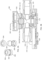
- the ball lens 216 When using a ball lens in a sealed optical setup, as shown in FIG. 2 , the ball lens 216 is inserted between the two flat optical windows 212 and 214.
- the two flat optical windows 212 and 214 can seal the fluid cell 202 with the use of O-rings (not specifically shown in FIG. 2 ).
- O-rings cannot be used directly with the ball lens 216 in examples in which the ball lens 216 is in contact with a flat surface (e.g., flat optical windows 212 and 214) to maintain a homogeneous pressure over the surface contact area. Therefore, in some examples, ball seats may be used in lieu of O-rings to seal the fluid cell 202. Ball seats may replace not only the O-rings, but the entire sealing system including the flat optical window 212.
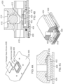
- FIGs. 4A-4D are diagrams illustrating an example of an optical fluid analyzer 400 including a package glass window sealing system according to some aspects.
- the optical fluid analyzer 400 includes a spectrometer 402 integrated within a package 404 that is assembled on a substrate 408 (e.g., a PCB).
- the package 404 includes an opening configured to receive a package glass window 406.
- the two half-ball lenses 612 and 614 design is easier in term of sealing the fluid cell 610 (e.g., O-rings may be used for sealing instead of ball lens seats).
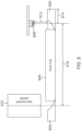
- FIG. 7 is a diagram illustrating another example of a collimated optical coupling design according to some aspects.
- the ball or half-ball lenses can be replaced by Plano convex lenses 702 and 704.
- the collimated setup uses a reflector 710 inserted behind the light source 708 to collect back rays of the light source and reflect the back rays towards the Plano convex lens 704 for coupling into a fluid cell 706 to nearly double the optical power.
- the Plano convex lenses 702 and 704 may be calcium fluoride lenses with focal lengths 716 and 718 of 18 mm to accommodate a fluid path length 714 of 50 mm.
- the off-axis parabolic mirror 902 has a focal length of 15 mm and the lens 904 has a focal length of 18 mm.
- a distance 912 between the light source 908 and the off-axis parabolic mirror 902 may be 8.65 mm and the off-axis parabolic mirror 902 may have a width 914 of 12.3 mm with a fluid cell length 916 of 100 mm. It should be understood that the focal lengths, distance 912, width 914 of the mirrors 902 and 904, and fluid cell length 916 are variable, and not limited to the examples provided herein.
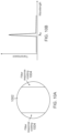
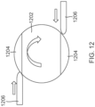
- FIGs. 10A and 10B are diagrams illustrating an optical coupling design, according to the invention, for calibration of the optical fluid analyzer according to some aspects.
- the optical coupling design shown in FIG. 10 includes a ball lens 1002 having a filter response coating 1004 on opposing ends thereof.
- the center area of the ball lens 1002 is not coated with the filter response coating 1004.
- the coating 1004 absorbs all wavelengths except for a reference wavelength ⁇ o used by the calibration.
- the response of the coating 1004 is shown in FIG. 10B .
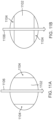
- FIGs. 11A and 11B illustrate modes of operation of a coated ball lens 1102 according to the invention.
- a first mode as shown in FIG. 11A , the filter response coating 1104 of the ball lens 1102 is out of a light path 1106 of input light from a light source (not shown). Therefore, no absorption of the input light occurs and the spectrum reflects the absorption of the fluid in a fluid cell (not shown).
- a second mode as shown in FIG. 11B , the light path 1106 of the input light passes through the filter response coating 1104 of the ball lens 1102, and as a result, absorption occurs producing the spectrum shown in FIG. 10B .
- the second mode may thus be referred to as a calibration mode.
- FIGs. 14A-14C are diagrams illustrating an example of an optical coupling design with variable optical path length according to some aspects.
- the optical coupling design includes two optical elements 1402 and 1404 for coupling input light into a fluid cell 1406 on a first side thereof and coupling output light from the fluid cell 1406 via a second side thereof.
- the optical elements 1402 and 1404 may include, for example, flat optical windows, ball lenses, half-ball lenses, Plano convex lenses, or other suitable optical coupling elements.
- To overcome the challenge of parasitic interference effect in a fluid cell 1406 due to the multiple reflections of light and the microscale path length 1410 in the fluid cell e.g.
- At least one of the optical elements can be coupled to an actuator 1408 (e.g., a micro/actuation mechanism) that is configured to cause motion of the optical element 1402 to continually vary the optical path length with motion d(t) in the fluid cell 1406 around a nominal value d o , as shown in FIG. 14A .
- the continuous motion of the optical element 1402 results in dithering of the optical path length, such that the average value of d(t) is zero, as shown in by comparison between FIGs. 14B (with no oscillatory motion) and 14C (with oscillatory motion).
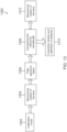
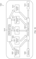
- FIG. 16 is a diagram illustrating an example of an optical fluid analyzer 1600 integrated with other sensors according to some aspects.
- the optical fluid analyzer 1600 includes a MEMS based FTIR fluid analyzer 1602 (e.g., including a light source, optical elements, fluid cell, and spectrometer (interferometer/detector)), artificial intelligence (AI) engine 1604 (e.g., ML engine), and database 1606 that are integrated with one or more other sensors.
- sensors include, but are not limited to, a pressure sensor 1608, a flow (fluid flow) sensor 1610, a temperature sensor 1612, and a humidity sensor 1614).
- the sensors 1608-1614 may be synchronized together and controlled via integrated electronics and synchronization signal circuitry 1616 to sense the fluid at the same time as the MEMS based FTIR fluid analyzer 1602 obtains a spectrum of the fluid.
- the output (e.g., sensor data related to the fluid in the fluid cell) of each sensor 1608-1614 may be input to the AI engine 1604, along with the spectrum of the fluid to aid the AI engine 1604 in predicting the fluid properties and specifications.
- the AI engine may further be trained with fluid data in the database 1606 to produce results 1618 related to the fluid.
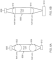
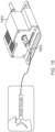
- FIG. 19 is a diagram illustrating an example of optical fluid analyzer 1900 configured for viral detection according to some aspects.
- the optical fluid analyzer 1900 can be configured to measure the spectrum of a patient breath sample and predict the type of viral infection of the patient.
- the ML engine (AI engine) of the optical fluid analyzer may predict the viral type from the absorption bands of the spectrum.
- the optical fluid analyzer 1900 can include an input tube 1902 through which a patient can blow air from their mouth into the fluid cell of the optical fluid analyzer 1900.
- FIGs. 1-19 One or more of the components, steps, features and/or functions illustrated in FIGs. 1-19 may be rearranged and/or combined into a single component, step, feature or function or embodied in several components, steps, or functions. Additional elements, components, steps, and/or functions may also be added without departing from novel features disclosed herein.
- the apparatus, devices, and/or components illustrated in FIGs. 1-19 may be configured to perform one or more of the methods, features, or steps described herein.
- the novel algorithms described herein may also be efficiently implemented in software and/or embedded in hardware. The invention is solely defined by the appended claims.
Landscapes
- Physics & Mathematics (AREA)
- Spectroscopy & Molecular Physics (AREA)
- Biochemistry (AREA)
- Life Sciences & Earth Sciences (AREA)
- Chemical & Material Sciences (AREA)
- Analytical Chemistry (AREA)
- Health & Medical Sciences (AREA)
- General Health & Medical Sciences (AREA)
- General Physics & Mathematics (AREA)
- Immunology (AREA)
- Pathology (AREA)
- Investigating Or Analysing Materials By Optical Means (AREA)
- Optical Measuring Cells (AREA)
Applications Claiming Priority (3)
| Application Number | Priority Date | Filing Date | Title |
|---|---|---|---|
| US202163210450P | 2021-06-14 | 2021-06-14 | |
| US17/839,102 US12031904B2 (en) | 2021-06-14 | 2022-06-13 | Optical fluid analyzer |
| PCT/US2022/033435 WO2022266098A1 (en) | 2021-06-14 | 2022-06-14 | Optical fluid analyzer |
Publications (3)
| Publication Number | Publication Date |
|---|---|
| EP4356111A1 EP4356111A1 (en) | 2024-04-24 |
| EP4356111B1 true EP4356111B1 (en) | 2025-03-12 |
| EP4356111C0 EP4356111C0 (en) | 2025-03-12 |
Family
ID=82403681
Family Applications (1)
| Application Number | Title | Priority Date | Filing Date |
|---|---|---|---|
| EP22738237.1A Active EP4356111B1 (en) | 2021-06-14 | 2022-06-14 | Optical fluid analyzer |
Country Status (3)
| Country | Link |
|---|---|
| EP (1) | EP4356111B1 (ja) |
| JP (1) | JP7841764B2 (ja) |
| WO (1) | WO2022266098A1 (ja) |
Family Cites Families (8)
| Publication number | Priority date | Publication date | Assignee | Title |
|---|---|---|---|---|
| EP1339142A1 (en) * | 2002-02-25 | 2003-08-27 | Agilent Technologies, Inc. - a Delaware corporation - | Means of suppression of non-bragg side modes |
| US8204565B2 (en) * | 2005-04-04 | 2012-06-19 | University Of Iowa Research Foundation | Reagentless optical analyte detection system |
| JP2008268107A (ja) * | 2007-04-24 | 2008-11-06 | Yokogawa Electric Corp | センサユニット及びマイクロリアクタシステム |
| US8896839B2 (en) * | 2008-07-30 | 2014-11-25 | Pason Systems Corp. | Multiplex tunable filter spectrometer |
| US8564768B2 (en) * | 2009-04-17 | 2013-10-22 | Schlumberger Technology Corporation | High pressure and high temperature optical spectroscopy cell using spherical surfaced lenses in direct contact with a fluid pathway |
| US20180059015A1 (en) * | 2016-08-30 | 2018-03-01 | Sensii, Inc. | Personal liquid analysis system |
| CA3054803C (en) * | 2017-02-28 | 2025-06-17 | MarqMetrix Inc. | CIRCULATING TANK INCLUDING A SPHERICAL GLASS |
| WO2019188304A1 (ja) * | 2018-03-29 | 2019-10-03 | パイオニア株式会社 | 検出装置 |
-
2022
- 2022-06-14 WO PCT/US2022/033435 patent/WO2022266098A1/en not_active Ceased
- 2022-06-14 JP JP2023576072A patent/JP7841764B2/ja active Active
- 2022-06-14 EP EP22738237.1A patent/EP4356111B1/en active Active
Also Published As
| Publication number | Publication date |
|---|---|
| JP7841764B2 (ja) | 2026-04-07 |
| WO2022266098A1 (en) | 2022-12-22 |
| EP4356111C0 (en) | 2025-03-12 |
| EP4356111A1 (en) | 2024-04-24 |
| JP2024522650A (ja) | 2024-06-21 |
Similar Documents
| Publication | Publication Date | Title |
|---|---|---|
| JP7588029B2 (ja) | サンプル検査のための装置、システムおよび方法 | |
| CN114008440B (zh) | 用于多气体光谱传感器的紧凑型多通道气室 | |
| US12385892B2 (en) | Self-calibrated spectroscopic and AI-based gas analyzer | |
| CN104049293B (zh) | 光学滤波器装置、光学模块以及电子设备 | |
| CN102667451B (zh) | 可变路径长度探测器 | |
| EP4239318A2 (en) | Apparatuses, systems, and methods for sample testing | |
| US8730466B2 (en) | Optical spectrometer with underfilled fiber optic sample interface | |
| US12228510B2 (en) | Integrated device for fluid analysis | |
| Jing et al. | Design and optimization of an integrated MEMS gas chamber with high transmissivity | |
| US12031904B2 (en) | Optical fluid analyzer | |
| US20260056130A1 (en) | Apparatuses, systems, and methods for sample testing | |
| EP4356111B1 (en) | Optical fluid analyzer | |
| US12553885B2 (en) | Apparatuses, systems, and methods for sample testing | |
| CN117836609A (zh) | 光学流体分析仪 | |
| JP7583006B2 (ja) | 試料試験のための装置 | |
| CN116698789A (zh) | 用于样品测试的装置、系统和方法 |
Legal Events
| Date | Code | Title | Description |
|---|---|---|---|
| STAA | Information on the status of an ep patent application or granted ep patent |
Free format text: STATUS: UNKNOWN |
|
| STAA | Information on the status of an ep patent application or granted ep patent |
Free format text: STATUS: THE INTERNATIONAL PUBLICATION HAS BEEN MADE |
|
| PUAI | Public reference made under article 153(3) epc to a published international application that has entered the european phase |
Free format text: ORIGINAL CODE: 0009012 |
|
| STAA | Information on the status of an ep patent application or granted ep patent |
Free format text: STATUS: REQUEST FOR EXAMINATION WAS MADE |
|
| 17P | Request for examination filed |
Effective date: 20231130 |
|
| AK | Designated contracting states |
Kind code of ref document: A1 Designated state(s): AL AT BE BG CH CY CZ DE DK EE ES FI FR GB GR HR HU IE IS IT LI LT LU LV MC MK MT NL NO PL PT RO RS SE SI SK SM TR |
|
| DAV | Request for validation of the european patent (deleted) | ||
| DAX | Request for extension of the european patent (deleted) | ||
| GRAP | Despatch of communication of intention to grant a patent |
Free format text: ORIGINAL CODE: EPIDOSNIGR1 |
|
| STAA | Information on the status of an ep patent application or granted ep patent |
Free format text: STATUS: GRANT OF PATENT IS INTENDED |
|
| RIC1 | Information provided on ipc code assigned before grant |
Ipc: G01N 21/05 20060101ALN20240920BHEP Ipc: G01N 21/03 20060101ALN20240920BHEP Ipc: G01N 21/35 20140101ALN20240920BHEP Ipc: G01N 21/3504 20140101AFI20240920BHEP |
|
| INTG | Intention to grant announced |
Effective date: 20241010 |
|
| GRAS | Grant fee paid |
Free format text: ORIGINAL CODE: EPIDOSNIGR3 |
|
| GRAA | (expected) grant |
Free format text: ORIGINAL CODE: 0009210 |
|
| STAA | Information on the status of an ep patent application or granted ep patent |
Free format text: STATUS: THE PATENT HAS BEEN GRANTED |
|
| AK | Designated contracting states |
Kind code of ref document: B1 Designated state(s): AL AT BE BG CH CY CZ DE DK EE ES FI FR GB GR HR HU IE IS IT LI LT LU LV MC MK MT NL NO PL PT RO RS SE SI SK SM TR |
|
| REG | Reference to a national code |
Ref country code: GB Ref legal event code: FG4D |
|
| REG | Reference to a national code |
Ref country code: CH Ref legal event code: EP |
|
| REG | Reference to a national code |
Ref country code: DE Ref legal event code: R096 Ref document number: 602022011772 Country of ref document: DE |
|
| REG | Reference to a national code |
Ref country code: IE Ref legal event code: FG4D |
|
| U01 | Request for unitary effect filed |
Effective date: 20250312 |
|
| U07 | Unitary effect registered |
Designated state(s): AT BE BG DE DK EE FI FR IT LT LU LV MT NL PT RO SE SI Effective date: 20250318 |
|
| PG25 | Lapsed in a contracting state [announced via postgrant information from national office to epo] |
Ref country code: RS Free format text: LAPSE BECAUSE OF FAILURE TO SUBMIT A TRANSLATION OF THE DESCRIPTION OR TO PAY THE FEE WITHIN THE PRESCRIBED TIME-LIMIT Effective date: 20250612 |
|
| PG25 | Lapsed in a contracting state [announced via postgrant information from national office to epo] |
Ref country code: ES Free format text: LAPSE BECAUSE OF FAILURE TO SUBMIT A TRANSLATION OF THE DESCRIPTION OR TO PAY THE FEE WITHIN THE PRESCRIBED TIME-LIMIT Effective date: 20250312 |
|
| PG25 | Lapsed in a contracting state [announced via postgrant information from national office to epo] |
Ref country code: NO Free format text: LAPSE BECAUSE OF FAILURE TO SUBMIT A TRANSLATION OF THE DESCRIPTION OR TO PAY THE FEE WITHIN THE PRESCRIBED TIME-LIMIT Effective date: 20250612 |
|
| PG25 | Lapsed in a contracting state [announced via postgrant information from national office to epo] |
Ref country code: HR Free format text: LAPSE BECAUSE OF FAILURE TO SUBMIT A TRANSLATION OF THE DESCRIPTION OR TO PAY THE FEE WITHIN THE PRESCRIBED TIME-LIMIT Effective date: 20250312 |
|
| PG25 | Lapsed in a contracting state [announced via postgrant information from national office to epo] |
Ref country code: GR Free format text: LAPSE BECAUSE OF FAILURE TO SUBMIT A TRANSLATION OF THE DESCRIPTION OR TO PAY THE FEE WITHIN THE PRESCRIBED TIME-LIMIT Effective date: 20250613 |
|
| U20 | Renewal fee for the european patent with unitary effect paid |
Year of fee payment: 4 Effective date: 20250630 |
|
| PG25 | Lapsed in a contracting state [announced via postgrant information from national office to epo] |
Ref country code: SM Free format text: LAPSE BECAUSE OF FAILURE TO SUBMIT A TRANSLATION OF THE DESCRIPTION OR TO PAY THE FEE WITHIN THE PRESCRIBED TIME-LIMIT Effective date: 20250312 |
|
| PG25 | Lapsed in a contracting state [announced via postgrant information from national office to epo] |
Ref country code: PL Free format text: LAPSE BECAUSE OF FAILURE TO SUBMIT A TRANSLATION OF THE DESCRIPTION OR TO PAY THE FEE WITHIN THE PRESCRIBED TIME-LIMIT Effective date: 20250312 |
|
| PG25 | Lapsed in a contracting state [announced via postgrant information from national office to epo] |
Ref country code: CZ Free format text: LAPSE BECAUSE OF FAILURE TO SUBMIT A TRANSLATION OF THE DESCRIPTION OR TO PAY THE FEE WITHIN THE PRESCRIBED TIME-LIMIT Effective date: 20250312 |
|
| PG25 | Lapsed in a contracting state [announced via postgrant information from national office to epo] |
Ref country code: SK Free format text: LAPSE BECAUSE OF FAILURE TO SUBMIT A TRANSLATION OF THE DESCRIPTION OR TO PAY THE FEE WITHIN THE PRESCRIBED TIME-LIMIT Effective date: 20250312 |
|
| PG25 | Lapsed in a contracting state [announced via postgrant information from national office to epo] |
Ref country code: IS Free format text: LAPSE BECAUSE OF FAILURE TO SUBMIT A TRANSLATION OF THE DESCRIPTION OR TO PAY THE FEE WITHIN THE PRESCRIBED TIME-LIMIT Effective date: 20250712 |
|
| PLBE | No opposition filed within time limit |
Free format text: ORIGINAL CODE: 0009261 |
|
| STAA | Information on the status of an ep patent application or granted ep patent |
Free format text: STATUS: NO OPPOSITION FILED WITHIN TIME LIMIT |
|
| REG | Reference to a national code |
Ref country code: CH Ref legal event code: L10 Free format text: ST27 STATUS EVENT CODE: U-0-0-L10-L00 (AS PROVIDED BY THE NATIONAL OFFICE) Effective date: 20260121 |
|
| REG | Reference to a national code |
Ref country code: CH Ref legal event code: H13 Free format text: ST27 STATUS EVENT CODE: U-0-0-H10-H13 (AS PROVIDED BY THE NATIONAL OFFICE) Effective date: 20260127 |
|
| PG25 | Lapsed in a contracting state [announced via postgrant information from national office to epo] |
Ref country code: MC Free format text: LAPSE BECAUSE OF FAILURE TO SUBMIT A TRANSLATION OF THE DESCRIPTION OR TO PAY THE FEE WITHIN THE PRESCRIBED TIME-LIMIT Effective date: 20250312 |
|
| 26N | No opposition filed |
Effective date: 20251215 |
|
| PG25 | Lapsed in a contracting state [announced via postgrant information from national office to epo] |
Ref country code: IE Free format text: LAPSE BECAUSE OF NON-PAYMENT OF DUE FEES Effective date: 20250614 |