EP4355602B1 - Verfahren zur steuerung des antriebs eines schwerlastfahrzeugs - Google Patents
Verfahren zur steuerung des antriebs eines schwerlastfahrzeugs Download PDFInfo
- Publication number
- EP4355602B1 EP4355602B1 EP21734296.3A EP21734296A EP4355602B1 EP 4355602 B1 EP4355602 B1 EP 4355602B1 EP 21734296 A EP21734296 A EP 21734296A EP 4355602 B1 EP4355602 B1 EP 4355602B1
- Authority
- EP
- European Patent Office
- Prior art keywords
- wheel
- speed
- slip
- shaft slip
- vehicle
- Prior art date
- Legal status (The legal status is an assumption and is not a legal conclusion. Google has not performed a legal analysis and makes no representation as to the accuracy of the status listed.)
- Active
Links
Images

Classifications
-
- B—PERFORMING OPERATIONS; TRANSPORTING
- B60—VEHICLES IN GENERAL
- B60K—ARRANGEMENT OR MOUNTING OF PROPULSION UNITS OR OF TRANSMISSIONS IN VEHICLES; ARRANGEMENT OR MOUNTING OF PLURAL DIVERSE PRIME-MOVERS IN VEHICLES; AUXILIARY DRIVES FOR VEHICLES; INSTRUMENTATION OR DASHBOARDS FOR VEHICLES; ARRANGEMENTS IN CONNECTION WITH COOLING, AIR INTAKE, GAS EXHAUST OR FUEL SUPPLY OF PROPULSION UNITS IN VEHICLES
- B60K28/00—Safety devices for propulsion-unit control, specially adapted for, or arranged in, vehicles, e.g. preventing fuel supply or ignition in the event of potentially dangerous conditions
- B60K28/10—Safety devices for propulsion-unit control, specially adapted for, or arranged in, vehicles, e.g. preventing fuel supply or ignition in the event of potentially dangerous conditions responsive to conditions relating to the vehicle
- B60K28/16—Safety devices for propulsion-unit control, specially adapted for, or arranged in, vehicles, e.g. preventing fuel supply or ignition in the event of potentially dangerous conditions responsive to conditions relating to the vehicle responsive to, or preventing, spinning or skidding of wheels
-
- B—PERFORMING OPERATIONS; TRANSPORTING
- B60—VEHICLES IN GENERAL
- B60T—VEHICLE BRAKE CONTROL SYSTEMS OR PARTS THEREOF; BRAKE CONTROL SYSTEMS OR PARTS THEREOF, IN GENERAL; ARRANGEMENT OF BRAKING ELEMENTS ON VEHICLES IN GENERAL; PORTABLE DEVICES FOR PREVENTING UNWANTED MOVEMENT OF VEHICLES; VEHICLE MODIFICATIONS TO FACILITATE COOLING OF BRAKES
- B60T8/00—Arrangements for adjusting wheel-braking force to meet varying vehicular or ground-surface conditions, e.g. limiting or varying distribution of braking force
- B60T8/17—Using electrical or electronic regulation means to control braking
- B60T8/175—Brake regulation specially adapted to prevent excessive wheel spin during vehicle acceleration, e.g. for traction control
-
- B—PERFORMING OPERATIONS; TRANSPORTING
- B60—VEHICLES IN GENERAL
- B60W—CONJOINT CONTROL OF VEHICLE SUB-UNITS OF DIFFERENT TYPE OR DIFFERENT FUNCTION; CONTROL SYSTEMS SPECIALLY ADAPTED FOR HYBRID VEHICLES; ROAD VEHICLE DRIVE CONTROL SYSTEMS FOR PURPOSES NOT RELATED TO THE CONTROL OF A PARTICULAR SUB-UNIT
- B60W10/00—Conjoint control of vehicle sub-units of different type or different function
- B60W10/04—Conjoint control of vehicle sub-units of different type or different function including control of propulsion units
-
- B—PERFORMING OPERATIONS; TRANSPORTING
- B60—VEHICLES IN GENERAL
- B60W—CONJOINT CONTROL OF VEHICLE SUB-UNITS OF DIFFERENT TYPE OR DIFFERENT FUNCTION; CONTROL SYSTEMS SPECIALLY ADAPTED FOR HYBRID VEHICLES; ROAD VEHICLE DRIVE CONTROL SYSTEMS FOR PURPOSES NOT RELATED TO THE CONTROL OF A PARTICULAR SUB-UNIT
- B60W10/00—Conjoint control of vehicle sub-units of different type or different function
- B60W10/12—Conjoint control of vehicle sub-units of different type or different function including control of differentials
- B60W10/16—Axle differentials, e.g. for dividing torque between left and right wheels
-
- B—PERFORMING OPERATIONS; TRANSPORTING
- B60—VEHICLES IN GENERAL
- B60W—CONJOINT CONTROL OF VEHICLE SUB-UNITS OF DIFFERENT TYPE OR DIFFERENT FUNCTION; CONTROL SYSTEMS SPECIALLY ADAPTED FOR HYBRID VEHICLES; ROAD VEHICLE DRIVE CONTROL SYSTEMS FOR PURPOSES NOT RELATED TO THE CONTROL OF A PARTICULAR SUB-UNIT
- B60W10/00—Conjoint control of vehicle sub-units of different type or different function
- B60W10/18—Conjoint control of vehicle sub-units of different type or different function including control of braking systems
-
- B—PERFORMING OPERATIONS; TRANSPORTING
- B60—VEHICLES IN GENERAL
- B60W—CONJOINT CONTROL OF VEHICLE SUB-UNITS OF DIFFERENT TYPE OR DIFFERENT FUNCTION; CONTROL SYSTEMS SPECIALLY ADAPTED FOR HYBRID VEHICLES; ROAD VEHICLE DRIVE CONTROL SYSTEMS FOR PURPOSES NOT RELATED TO THE CONTROL OF A PARTICULAR SUB-UNIT
- B60W30/00—Purposes of road vehicle drive control systems not related to the control of a particular sub-unit, e.g. of systems using conjoint control of vehicle sub-units
- B60W30/18—Propelling the vehicle
- B60W30/18172—Preventing, or responsive to skidding of wheels
-
- B—PERFORMING OPERATIONS; TRANSPORTING
- B60—VEHICLES IN GENERAL
- B60T—VEHICLE BRAKE CONTROL SYSTEMS OR PARTS THEREOF; BRAKE CONTROL SYSTEMS OR PARTS THEREOF, IN GENERAL; ARRANGEMENT OF BRAKING ELEMENTS ON VEHICLES IN GENERAL; PORTABLE DEVICES FOR PREVENTING UNWANTED MOVEMENT OF VEHICLES; VEHICLE MODIFICATIONS TO FACILITATE COOLING OF BRAKES
- B60T2201/00—Particular use of vehicle brake systems; Special systems using also the brakes; Special software modules within the brake system controller
- B60T2201/16—Curve braking control, e.g. turn control within ABS control algorithm
-
- B—PERFORMING OPERATIONS; TRANSPORTING
- B60—VEHICLES IN GENERAL
- B60T—VEHICLE BRAKE CONTROL SYSTEMS OR PARTS THEREOF; BRAKE CONTROL SYSTEMS OR PARTS THEREOF, IN GENERAL; ARRANGEMENT OF BRAKING ELEMENTS ON VEHICLES IN GENERAL; PORTABLE DEVICES FOR PREVENTING UNWANTED MOVEMENT OF VEHICLES; VEHICLE MODIFICATIONS TO FACILITATE COOLING OF BRAKES
- B60T2270/00—Further aspects of brake control systems not otherwise provided for
- B60T2270/20—ASR control systems
- B60T2270/213—Driving off under Mu-split conditions
-
- B—PERFORMING OPERATIONS; TRANSPORTING
- B60—VEHICLES IN GENERAL
- B60T—VEHICLE BRAKE CONTROL SYSTEMS OR PARTS THEREOF; BRAKE CONTROL SYSTEMS OR PARTS THEREOF, IN GENERAL; ARRANGEMENT OF BRAKING ELEMENTS ON VEHICLES IN GENERAL; PORTABLE DEVICES FOR PREVENTING UNWANTED MOVEMENT OF VEHICLES; VEHICLE MODIFICATIONS TO FACILITATE COOLING OF BRAKES
- B60T8/00—Arrangements for adjusting wheel-braking force to meet varying vehicular or ground-surface conditions, e.g. limiting or varying distribution of braking force
- B60T8/17—Using electrical or electronic regulation means to control braking
- B60T8/176—Brake regulation specially adapted to prevent excessive wheel slip during vehicle deceleration, e.g. ABS
- B60T8/1764—Regulation during travel on surface with different coefficients of friction, e.g. between left and right sides, mu-split or between front and rear
-
- B—PERFORMING OPERATIONS; TRANSPORTING
- B60—VEHICLES IN GENERAL
- B60W—CONJOINT CONTROL OF VEHICLE SUB-UNITS OF DIFFERENT TYPE OR DIFFERENT FUNCTION; CONTROL SYSTEMS SPECIALLY ADAPTED FOR HYBRID VEHICLES; ROAD VEHICLE DRIVE CONTROL SYSTEMS FOR PURPOSES NOT RELATED TO THE CONTROL OF A PARTICULAR SUB-UNIT
- B60W2300/00—Indexing codes relating to the type of vehicle
- B60W2300/14—Tractor-trailers, i.e. combinations of a towing vehicle and one or more towed vehicles, e.g. caravans; Road trains
- B60W2300/145—Semi-trailers
-
- B—PERFORMING OPERATIONS; TRANSPORTING
- B60—VEHICLES IN GENERAL
- B60W—CONJOINT CONTROL OF VEHICLE SUB-UNITS OF DIFFERENT TYPE OR DIFFERENT FUNCTION; CONTROL SYSTEMS SPECIALLY ADAPTED FOR HYBRID VEHICLES; ROAD VEHICLE DRIVE CONTROL SYSTEMS FOR PURPOSES NOT RELATED TO THE CONTROL OF A PARTICULAR SUB-UNIT
- B60W2510/00—Input parameters relating to a particular sub-units
- B60W2510/10—Change speed gearings
- B60W2510/104—Output speed
-
- B—PERFORMING OPERATIONS; TRANSPORTING
- B60—VEHICLES IN GENERAL
- B60W—CONJOINT CONTROL OF VEHICLE SUB-UNITS OF DIFFERENT TYPE OR DIFFERENT FUNCTION; CONTROL SYSTEMS SPECIALLY ADAPTED FOR HYBRID VEHICLES; ROAD VEHICLE DRIVE CONTROL SYSTEMS FOR PURPOSES NOT RELATED TO THE CONTROL OF A PARTICULAR SUB-UNIT
- B60W2510/00—Input parameters relating to a particular sub-units
- B60W2510/20—Steering systems
-
- B—PERFORMING OPERATIONS; TRANSPORTING
- B60—VEHICLES IN GENERAL
- B60W—CONJOINT CONTROL OF VEHICLE SUB-UNITS OF DIFFERENT TYPE OR DIFFERENT FUNCTION; CONTROL SYSTEMS SPECIALLY ADAPTED FOR HYBRID VEHICLES; ROAD VEHICLE DRIVE CONTROL SYSTEMS FOR PURPOSES NOT RELATED TO THE CONTROL OF A PARTICULAR SUB-UNIT
- B60W2520/00—Input parameters relating to overall vehicle dynamics
- B60W2520/06—Direction of travel
-
- B—PERFORMING OPERATIONS; TRANSPORTING
- B60—VEHICLES IN GENERAL
- B60W—CONJOINT CONTROL OF VEHICLE SUB-UNITS OF DIFFERENT TYPE OR DIFFERENT FUNCTION; CONTROL SYSTEMS SPECIALLY ADAPTED FOR HYBRID VEHICLES; ROAD VEHICLE DRIVE CONTROL SYSTEMS FOR PURPOSES NOT RELATED TO THE CONTROL OF A PARTICULAR SUB-UNIT
- B60W2520/00—Input parameters relating to overall vehicle dynamics
- B60W2520/10—Longitudinal speed
-
- B—PERFORMING OPERATIONS; TRANSPORTING
- B60—VEHICLES IN GENERAL
- B60W—CONJOINT CONTROL OF VEHICLE SUB-UNITS OF DIFFERENT TYPE OR DIFFERENT FUNCTION; CONTROL SYSTEMS SPECIALLY ADAPTED FOR HYBRID VEHICLES; ROAD VEHICLE DRIVE CONTROL SYSTEMS FOR PURPOSES NOT RELATED TO THE CONTROL OF A PARTICULAR SUB-UNIT
- B60W2520/00—Input parameters relating to overall vehicle dynamics
- B60W2520/26—Wheel slip
- B60W2520/266—Slip values between left and right wheel
-
- B—PERFORMING OPERATIONS; TRANSPORTING
- B60—VEHICLES IN GENERAL
- B60W—CONJOINT CONTROL OF VEHICLE SUB-UNITS OF DIFFERENT TYPE OR DIFFERENT FUNCTION; CONTROL SYSTEMS SPECIALLY ADAPTED FOR HYBRID VEHICLES; ROAD VEHICLE DRIVE CONTROL SYSTEMS FOR PURPOSES NOT RELATED TO THE CONTROL OF A PARTICULAR SUB-UNIT
- B60W2520/00—Input parameters relating to overall vehicle dynamics
- B60W2520/28—Wheel speed
-
- B—PERFORMING OPERATIONS; TRANSPORTING
- B60—VEHICLES IN GENERAL
- B60W—CONJOINT CONTROL OF VEHICLE SUB-UNITS OF DIFFERENT TYPE OR DIFFERENT FUNCTION; CONTROL SYSTEMS SPECIALLY ADAPTED FOR HYBRID VEHICLES; ROAD VEHICLE DRIVE CONTROL SYSTEMS FOR PURPOSES NOT RELATED TO THE CONTROL OF A PARTICULAR SUB-UNIT
- B60W2520/00—Input parameters relating to overall vehicle dynamics
- B60W2520/30—Wheel torque
-
- B—PERFORMING OPERATIONS; TRANSPORTING
- B60—VEHICLES IN GENERAL
- B60W—CONJOINT CONTROL OF VEHICLE SUB-UNITS OF DIFFERENT TYPE OR DIFFERENT FUNCTION; CONTROL SYSTEMS SPECIALLY ADAPTED FOR HYBRID VEHICLES; ROAD VEHICLE DRIVE CONTROL SYSTEMS FOR PURPOSES NOT RELATED TO THE CONTROL OF A PARTICULAR SUB-UNIT
- B60W2710/00—Output or target parameters relating to a particular sub-units
- B60W2710/10—Change speed gearings
- B60W2710/1038—Output speed
-
- B—PERFORMING OPERATIONS; TRANSPORTING
- B60—VEHICLES IN GENERAL
- B60W—CONJOINT CONTROL OF VEHICLE SUB-UNITS OF DIFFERENT TYPE OR DIFFERENT FUNCTION; CONTROL SYSTEMS SPECIALLY ADAPTED FOR HYBRID VEHICLES; ROAD VEHICLE DRIVE CONTROL SYSTEMS FOR PURPOSES NOT RELATED TO THE CONTROL OF A PARTICULAR SUB-UNIT
- B60W2710/00—Output or target parameters relating to a particular sub-units
- B60W2710/18—Braking system
Definitions
- the present disclosure relates to methods and control units for ensuring safe and efficient vehicle motion management of a heavy-duty vehicle.
- the methods are particularly suitable for use with cargo transporting vehicles, such as trucks and semi-trailers.
- cargo transporting vehicles such as trucks and semi-trailers.
- the invention referred to in this disclosure can, however, also be applied in other types of heavy-duty vehicles, e.g., in construction equipment and in mining vehicles, as well as in cars.
- Heavy-duty vehicles such as trucks and semi-trailer vehicles, are designed to carry heavy loads.
- the heavily laden vehicles must be able to start from standstill also in uphill conditions and accelerate reliably on various types of road surfaces.
- Excessive wheel slip occurs when too much torque is applied to an axle, or to a wheel compared to what is supported by the current road friction and normal load. Excessive wheel slip is undesired since it results in an unpredictable vehicle behavior, loss of tractive force, and also in an energy inefficient operation.
- GB2562308 A discusses wheel slip and proposes methods for limiting a maximum regenerative braking torque which can be applied to a wheel.
- the controller uses a tyre model to determine a maximum usable traction for each wheel and calculates the maximum regenerative braking force to be applied to each wheel based on this tyre model.
- a differential drive arrangement allows a single power source, such as a combustion engine or an electric machine, to power both wheels on a driven axle.
- An open differential drive arrangement distributes torque evenly over the drive axle.
- the power transferred to the wheels will differ. This problem may become especially pronounced in so-called split friction conditions, where severely sub-optimal propulsion can be experienced.
- EP1396402B1 discloses a method for controlling motion of a heavy-duty vehicle, where the vehicle comprises an open differential driven axle, and where the vehicle wheel forces are controlled based on a wheel slip target.
- US2018134156 discusses a reduction of the target slip value in response to a large wheel speed difference.
- US 2021078581 A1 discloses methods for controlling wheel slip of a vehicle.
- This object is at least in part obtained by a method for controlling propulsion of a heavy-duty vehicle, where the heavy-duty vehicle comprises a differential drive arrangement arranged in connection to a drive axle with a left wheel and a right wheel.
- the method comprises determining a nominal shaft slip corresponding to a desired wheel force to be generated by the drive axle wheels, wherein the nominal shaft slip is indicative of a difference between a current vehicle velocity and a vehicle velocity corresponding to the shaft speed.
- the method also comprises determining a difference between a speed of the left wheel and a speed of the right wheel, and adjusting the nominal shaft slip in dependence of a magnitude of the wheel speed difference to a target shaft slip and also controlling the shaft speed based on the target shaft slip.
- the vehicle control systems discussed herein are able to react quickly to a detected wheel speed difference in order to, e.g., maintain traction.
- the proposed system advantageously complements known traction control systems which apply friction brakes or the like to transfer torque away from a spinning wheel of an open differential.
- the proposed methods adjust shaft speed already for relatively small wheel speed differences, and is thereby able to improve traction before the actual traction control system kicks in. It is an advantage that the shaft speed control can be actuated with low latency, since the forward motion of a heavy-duty vehicle in, e.g., an uphill driving condition with uneven friction on the sides of the vehicle, can be maintained.
- the target shaft slip may for instance be obtained by multiplying the nominal shaft slip by a reduction factor ⁇ ⁇ 1, where the reduction factor ⁇ decreases with the magnitude of the wheel speed difference.
- the actual function for determining the reduction factor may be configured specifically for a given vehicle, or for a given type of vehicle, thus customizing the control methods for even higher performance.
- the method may also comprise controlling the shaft speed based on the target shaft slip by adjusting the shaft speed to obtain the target shaft slip.
- the method also comprises configuring the target shaft slip equal to the nominal shaft slip if the magnitude of the difference between the speed of the left wheel and the speed of the right wheel is below a pre-determined threshold. This way the shaft slip is not reduced until the wheel slip difference is deemed significant. The frequency of control intervention is thereby reduced, which can be an advantage in some scenarios.
- the method comprises triggering a service brake intervention procedure in case the magnitude of the difference between the speed of the left wheel and the speed of the right wheel exceeds a split- ⁇ condition threshold.
- the herein proposed methods may be used with advantage together with legacy traction control system, which apply brake torque to the spinning wheel in order to transfer torque over to the wheel with more traction.
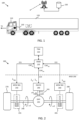
- FIG. 1 illustrates a heavy-duty vehicle 100.
- This particular example comprises a tractor unit 110 which is arranged to tow a trailer unit 120.
- the tractor 110 comprises a vehicle electronic control unit (ECU) 130 arranged to control various functions of the vehicle 100.
- the ECU may be arranged to perform a vehicle motion management (VMM) function comprising control of wheel slip, vehicle unit stability, and so on.
- VMM vehicle motion management
- the trailer unit 120 optionally also comprises an ECU 140, which then controls one or more functions on the trailer 120.
- the ECU or ECUs may be communicatively coupled, e.g., via wireless link, to a remote server 150.
- This remote server may be arranged to perform configuration of the ECU, and to provide various forms of data to the ECU 130, such as providing data regarding the make and type of tyres mounted on the vehicle 100, and information related to a relationship between generated wheel force and wheel slip, i.e., an inverse tyre model, as will be discussed in more detail below in connection to Figure 3 .
- the vehicle combination 100 may of course also comprise additional vehicle units, such as one or more dolly units and more than one trailer unit.
- additional vehicle units such as one or more dolly units and more than one trailer unit.
- the techniques disclosed herein are applicable to rigid trucks, and also to passenger cars, although the main benefit of the proposed technique is obtained when used with heavy-duty vehicle for cargo transport.
- Propulsion of a heavy-duty vehicle like the vehicle 100 has traditionally been controlled using control loops based on torque requests.
- the torque-based control loops of a heavy duty vehicle are normally associated with time constants on the order of 10 ms or so. In some scenarios this time constant reduces overall vehicle control bandwidth to a point where the startability and overall vehicle motion management of the heavy duty vehicle may be negatively affected, especially when road friction is uneven.
- the propulsion device on the vehicle 100 is requested by the ECU 130 to maintain wheel slip at a target wheel slip value ⁇ target which has been determined in order to obtain a desired motion by the vehicle. For instance, if the target wheel slip is set at 0.1, then the wheel rotational velocity will be continuously set at a relative difference of 0.1 above the vehicle velocity so that the wheel will always be slipping by the configured amount.
- this control strategy is different compared to just imposing a wheel slip limit, and performing torque-based on control of the propulsion as long as the wheel slip stays below the configured wheel slip limit.
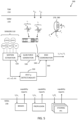
- FIG. 2 schematically illustrates functionality 300 for controlling a left wheel 270 and a right wheel 280 on a driven axle 246 by some example MSDs, here comprising friction brakes 255 (such as disc brakes or drum brakes) and a propulsion device 240 such as an electric machine (EM) or a combustion engine (CE).
- the friction brakes 255, 265 and the propulsion device 240 are examples of wheel torque generating devices, which may also be referred to as actuators and which can be controlled by one or more motion support device control units 250, 260.
- the service brakes SB1, SB2 are assumed to be controlled by respective wheel end module (WEM) controllers 250, 260, while the propulsion device 240 comprises an integrated control unit not shown in Figure 2 .
- WEM wheel end module
- the propulsion device 240 is connected to the drive axle 246 via a differential drive arrangement 245.
- This differential drive arrangement may, e.g., be an open differential which distributes torque evenly over the two wheels.
- a traffic situation management (TSM) function 210 plans driving operations with a time horizon of, e.g., 1-10 seconds or so. This time frame corresponds to, e.g., the time it takes for the vehicle 100 to negotiate a curve.
- the vehicle maneuvers, planned and executed by the TSM can be associated with acceleration profiles and curvature profiles which describe a desired vehicle velocity and turning for a given maneuver.
- the TSM continuously requests the desired acceleration profiles a req and curvature profiles c req from the VMM function 220 which performs force allocation to meet the requests from the TSM in a safe and robust manner, based at least in part based on capability reports (CAP) received from the various MSD control units.
- CAP capability reports
- Desired acceleration profiles and curvature profiles may optionally be determined based on input from a driver via a human machine interface of the heavy-duty vehicle via normal control input devices such as a steering wheel, accelerator pedal and brake pedal, although the techniques disclosed herein are just as applicable with autonomous or semi-autonomous vehicles.
- the exact methods used for determining the acceleration profiles and curvature profiles is not within scope of the present disclosure and will therefore not be discussed in more detail herein.
- the control commands i.e., the requests sent to the MSD controllers 240, 250, 260 from the VMM function 210 comprises wheel slips ⁇ to be maintained by the respective MSDs.
- Both the friction brakes and the propulsion device interact with the road surface via wheels 270, 280 comprising respective tyres.
- the tyre properties and behavioral characteristics has an impact on how the different control actions by the friction brakes and the propulsion device generate vehicle motion.
- a software-based tyre model is optionally comprised in the system. This tyre model provides information about the tyre currently mounted on the wheel, its properties, and behavioral characteristics.
- the tyre model may, as mentioned above, be implemented as a look-up table or other type of function.
- the tyre model is parameterized, i.e., defined, by one or more tyre parameters. This means that the function itself varies in dependence of the tyre properties.
- the tyre model can be used to model various relationships, as exemplified above, such as a relationship or mapping between wheel slip and generated wheel force, and/or a mapping between tyre wear rate and vehicle state such as tyre normal load, vehicle speed, and wheel slip. It is appreciated that the present disclosure is not limited to any particular form of tyre model structure. Rather, it is appreciated that many different types of mathematical and/or experimentally based functions and mappings can be used as the tyre model.
- a tyre model can be used to define a relationship between longitudinal tyre force Fx for a given wheel and an equivalent longitudinal wheel slip for the wheel.
- Longitudinal wheel slip ⁇ x relates to a difference between wheel rotational velocity and speed over ground and will be discussed in more detail below.
- Wheel, axle or shaft rotation speed ⁇ is a rotational speed given in units of, e.g., rotations per minute (rpm) or angular velocity in terms radians/second (rad/sec) or degrees/second (deg/sec).
- the wheel behavior in terms of wheel force generated in longitudinal direction (in the rolling direction) and/or lateral direction (orthogonal to the longitudinal direction) as function of wheel slip is discussed in " Tyre and vehicle dynamics", Elsevier Ltd. 2012, ISBN 978-0-08-097016-5, by Hans Pacejka . See, e.g., chapter 7 where the relationship between wheel slip and longitudinal force is discussed.
- ⁇ x is bounded between -1 and 1 and quantifies how much the wheel is slipping with respect to the road surface.
- Wheel slip is, in essence, a speed difference measured between the wheel and the vehicle.
- the herein disclosed techniques can be adapted for use with any type of wheel slip definition. It is also appreciated that a wheel slip value is equivalent to a wheel speed value given a velocity of the wheel over the surface, in the coordinate system of the wheel.
- the present disclosure relates primarily to longitudinal wheel slip, although it is appreciated that the two are connected, mainly since the ability to generate lateral wheel force depends strongly on the longitudinal wheel slip.
- a tyre is subject to a longitudinal force F x , a lateral force F y , and a normal force F z .
- the normal force F z is key to determining some important vehicle properties. For instance, the normal force to a large extent determines the achievable longitudinal tyre force F x by the wheel since, normally, F x ⁇ ⁇ F z , where ⁇ is a friction coefficient associated with a road friction condition.
- the maximum available lateral force for a given lateral slip can be described by the so-called Magic Formula as described in " Tyre and vehicle dynamics", Elsevier Ltd. 2012, ISBN 978-0-08-097016-5, by Hans Pacejka .
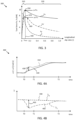
- FIG. 3 shows a graph 300 illustrating an example of achievable tyre forces F x , F y as function of wheel slip.
- the longitudinal tyre force Fx shows an almost linearly increasing part 310 for small wheel slips, followed by a part 320 with more non-linear behavior for larger wheel slips.
- the obtainable lateral tyre force Fy decreases rapidly even at relatively small longitudinal wheel slips.
- a wheel slip limit ⁇ LIM on the order of, e.g., 0.1, can be imposed on a given wheel, which ensures operation in the linear region 310.
- the VMM function 210 operates with a time horizon of about 0,1-1,5 seconds or so, and continuously transforms the acceleration profiles a req and curvature profiles c req into control commands for controlling vehicle motion functions, actuated by the different MSDs of the vehicle 100 which report back capabilities to the VMM, which in turn are used as constraints in the vehicle control.
- the accuracy of this control is improved by means of the advanced tyre models 380 discussed herein.
- the VMM function 210 performs vehicle state or motion estimation 520, i.e., the VMM function 210 continuously determines a vehicle state s (often a vector variable) comprising positions, speeds, accelerations, yaw motions, normal forces and articulation angles of the different units in the vehicle combination by monitoring vehicle state and behavior using various sensors 510 arranged on the vehicle 100, often but not always in connection to the MSDs.
- vehicle state s often a vector variable
- the result of the motion estimation 520 i.e., the estimated vehicle state s , is input to a global force generation module 530 which determines the required global forces on the vehicle units which need to be generated in order to meet the motion requests from the TSM 210.
- An MSD coordination function 540 allocates, e.g., wheel forces and coordinates other MSDs such as steering and suspension. The coordinated MSDs then together provide the desired lateral Fy and longitudinal Fx forces on the vehicle units, as well as the required moments Mz, to obtain the desired motion by the vehicle combination 100.
- the MSD coordination function 540 may output any of wheel slips ⁇ i , wheel rotation speeds ⁇ , and/or steering angles ⁇ I to the different MSDs.
- a split- ⁇ control module 550 is arranged to monitor wheel speed differences, and to intervene in case the wheel speeds diverge. When this happens, a control signal is sent to the MSD coordination module 540 which will reduce the configured shaft slip in response to the control signal 560. Thus, the wheel speed is rapidly brought back under control.
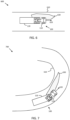
- Figure 6 illustrates an example split- ⁇ scenario 600, where a heavy-duty vehicle 100 drives straight on a road 610 in a forward direction with vehicle velocity v x 620.
- a region of low friction 630 is encountered by the left wheels of the vehicle 100.
- the left-hand side wheels may start to spin faster than the right-hand side wheels. giving rise to the sub-optimal operating points illustrated in Figure 3 , i.e., where one wheel is to the right of the nominal desired slip and the other wheel is to the left of the desired operating point.
- the herein proposed techniques will then quickly step in and reduce the shaft slip down to a level where the speed of the spinning wheel is reduced, thus improving overall traction very fast, much faster than would have been possible using legacy traction control system based on slow torque-based control of service brakes.
- the methods proposed herein also act in a more continuous manner, and may be configured to activate already at small wheel speed differences. Traction control system often require larger wheel speed differences before they kick in, due to robustness reasons.
- FIG. 7 illustrates another example scenario 700, but now the vehicle is cornering, i.e., follows a path associated with a curvature.
- the curvature itself gives rise to a difference in wheel speeds.
- This wheel speed difference is preferably accounted for by the method, i.e., such wheel speed differences due to planned curve taking will optionally not result in a modified shaft slip.
- the vehicle 100 encounters a region 630 of low friction, which causes the wheel speed difference to deviate from that expected from the curvature, which may cause a reduction in shaft slip request to the propulsion device.
- FIG. 8 is a flow chart which summarizes the herein disclosed techniques. There is illustrated a method for controlling propulsion of a heavy-duty vehicle 100, where the heavy-duty vehicle 100 comprises a differential drive arrangement 245 arranged in connection to a drive axle 246 with a left wheel 270 and a right wheel 280, as discussed above in connection to Figure 2 .
- the method comprises determining S1 a nominal shaft slip ⁇ 0 , 440 corresponding to a desired wheel force Fx to be generated by the drive axle wheels 270, 280, wherein the nominal shaft slip is indicative of a difference between a current vehicle velocity v x and a vehicle velocity corresponding to the shaft speed ⁇ 0.
- Shaft slip is a measure of the difference between how fast the shaft is rotating compared to how fast the vehicle is moving, of course accounting for the total gear ratio, wheel radius, and so on.
- Shaft slip is akin to a measure of wheel slip, albeit measured in the drive shaft instead of on the wheel axle.
- the nominal shaft slip may, e.g., be determined by the MSD coordination module 540 discussed in connection to Figure 5 in order to obtain a desired total wheel force from the wheels on the driven axle.
- a tyre model such as that discussed in connection to Figure 3 may be used to translate between desired tyre force and shaft slip.
- the method also comprises determining S2 a difference between a speed ⁇ 1 of the left wheel and a speed ⁇ 2 of the right wheel.
- This wheel speed difference or at least the magnitude thereof, is preferably determined by using left and right-hand side wheel speed sensors.
- the difference in wheel speeds may then be determined with high bandwidth, i.e., with an update latency on the order of 1 ms or less, by the MSD control units 230 and/or by the VMM unit 220.
- the vehicle ECU 130 also has access to accurate information about the speed of the vehicle in the forward direction, which means that accurate determination of shaft slip is enabled.
- the difference between the speed ⁇ 1 of the left wheel and the speed ⁇ 2 of the right wheel is adjusted S32 based on a vehicle path curvature c req and/or on a vehicle steering angle ⁇ .
- the actual adjustment may be obtained from a model of the vehicle, comprising vehicle dimensions and the like, or simply tabulated based on practical experimentation. An example scenario comprising cornering when encountering split friction conditions were discussed above in connection to Figure 7 .
- the method comprises adjusting S3 the nominal shaft slip ⁇ 0 , 440 in dependence of a magnitude of the wheel speed difference to a target shaft slip ⁇ T , 460, and controlling S4 the shaft speed ⁇ 0 based on the target shaft slip ⁇ T , 460, e.g., by adjusting the shaft speed ⁇ 0 to obtain the target shaft slip ⁇ T , 460.
- the proposed method immediately reduces the nominal shaft slip down to a lower target shaft slip. This means that the rightmost operating point on the inverse tyre model curve is shifted to the left, with a resulting improved vehicle propulsion.
- the control can be made very fast, i.e., with very small latency.
- the target shaft slip ⁇ T , 460 is obtained S31 by multiplying the nominal shaft slip ⁇ 0 , 440 by a reduction factor ⁇ ⁇ 1, where the reduction factor ⁇ decreases with the magnitude of the wheel speed difference.
- This reduction factor is generally a function of the wheel speed difference magnitude.
- the method may also comprise configuring S33 the target shaft slip ⁇ T , 460 to be equal to the nominal shaft slip ⁇ 0 , 440 if the magnitude of the difference between the speed ⁇ 1 of the left wheel and the speed ⁇ 2 of the right wheel is below a pre-determined threshold.
- the herein disclosed methods can be triggered only if the wheel speed difference exceeds some value considered substantial, and be left inactivated as long as the wheel speeds only differ by some small value below the threshold.
- the magnitude of w determines the bandwidth constraint. A large w allows for rapid convergence, and vice versa.
- the magnitude of w may be selected as a function of the rate of change in the wheel speed difference, i.e., if ⁇ 1 k ⁇ ⁇ 2 k ⁇ ⁇ 1 k + 1 ⁇ ⁇ 2 k + 1 then wheel speed difference is increasing and w is then selected larger compared to the case where ⁇ 1 k ⁇ ⁇ 2 k > ⁇ 1 k + 1 ⁇ ⁇ 2 k + 1
- the target shaft slip ⁇ T , 460 is adapted S34 according to a bandwidth constraint, where the bandwidth constraint is smaller for a decreasing target shaft slip ⁇ T , 460 compared to an increasing target shaft slip ⁇ T , 460.
- the target shaft slip ⁇ T , 460 is optionally also adapted S35 such that neither of the speed ⁇ 1 of the left wheel and the speed ⁇ 2 of the right wheel exceeds a wheel slip limit configured in dependence of the nominal shaft slip ⁇ 0 , 440.
- This can be realized in a number of different ways. For instance, with reference to Figure 3 , in case one of the wheel slips 360, 370 exceeds a pre-determined slip limit of, say 0.1, then the shaft speed ⁇ 0 is reduced until both wheels show wheel slips below the configured wheel slip threshold. This implies that the nominal shaft slip ⁇ 0 , 440 is reduced down to a target shaft slip ⁇ T ⁇ ⁇ 0 at which both wheels operate below the slip limit.
- the methods disclosed herein optionally also comprise triggering S5 a service brake intervention procedure in case the magnitude of the difference between the speed ⁇ 1 of the left wheel and the speed ⁇ 2 of the right wheel exceeds a split- ⁇ condition threshold.
- the herein proposed methods may be used as a complement to existing traction control systems which apply service brakes 255, 265 to transfer propulsion power away from a fast slipping wheel to the not-so fast slipping wheel.
- Such traction control methods are known and will therefore not be discussed in more detail herein.
- EP1396402B1 discloses a method for controlling motion of a heavy-duty vehicle, where the vehicle comprises an open differential driven axle, and where the vehicle wheel forces are controlled based on a wheel slip target, i.e., a wheel slip limit.
- EP1396402B1 discloses monitoring of a difference in wheel speeds over the driven axle, and reduces wheel slip if the difference in wheel speeds increases, such that neither of the wheel slips exceed the initial target slip value.
- EP1396402B1 does not relate to control of shaft slip.
- a relationship between nominal shaft slip ⁇ 0 , 440 and desired wheel force Fx is given by an inverse tyre model 300, as discussed above in connection to Figure 3 .
- the method then comprises initially obtaining S12 this inverse tyre model.
- the model may be pre-configured as a software update of the ECU 130, or obtained from the remote server 150.
- FIG. 7 schematically illustrates, in terms of a number of functional units, the components of a control unit 700 according to embodiments of the discussions herein, such as any of the VUCs 130, 140.
- This control unit 700 may be comprised in the articulated vehicle 1.
- Processing circuitry 710 is provided using any combination of one or more of a suitable central processing unit CPU, multiprocessor, microcontroller, digital signal processor DSP, etc., capable of executing software instructions stored in a computer program product, e.g. in the form of a storage medium 730.
- the processing circuitry 710 may further be provided as at least one application specific integrated circuit ASIC, or field programmable gate array FPGA.
- the processing circuitry 710 is configured to cause the control unit 700 to perform a set of operations, or steps, such as the methods discussed in connection to Figure 7 .
- the storage medium 730 may store the set of operations
- the processing circuitry 710 may be configured to retrieve the set of operations from the storage medium 730 to cause the control unit 700 to perform the set of operations.
- the set of operations may be provided as a set of executable instructions.
- the processing circuitry 710 is thereby arranged to execute methods as herein disclosed.
- control unit 130 arranged to control propulsion of a heavy-duty vehicle 100, where the heavy-duty vehicle 100 comprises a differential drive arrangement 245 arranged in connection to a drive axle 246 with a left wheel 270 and a right wheel 280, the control unit comprising processing circuitry 910 configured to
Landscapes
- Engineering & Computer Science (AREA)
- Transportation (AREA)
- Mechanical Engineering (AREA)
- Chemical & Material Sciences (AREA)
- Combustion & Propulsion (AREA)
- Automation & Control Theory (AREA)
- Regulating Braking Force (AREA)
Claims (16)
- Verfahren zur Antriebssteuerung eines Schwerlastfahrzeugs (100), wobei das Schwerlastfahrzeug (100) eine Differentialantriebsanordnung (245) umfasst, die in Verbindung mit einer Antriebsachse (246) mit einem linken Rad (270) und einem rechten Rad (280) angeordnet ist, das Verfahren umfassend einBestimmen (S1) eines Nenn-Wellenschlupfs (λ0, 440), der einer gewünschten Radkraft (Fx) entspricht, die von den Antriebsachsrädern (270, 280) erzeugt werden soll, wobei der Nenn-Wellenschlupf indikativ für eine Differenz zwischen einer aktuellen Fahrzeuggeschwindigkeit (vx ) und einer Fahrzeuggeschwindigkeit, die der Wellendrehzahl (ω0) entspricht, ist,Bestimmen (S2) einer Differenz zwischen einer Geschwindigkeit (ω1) des linken Rads und einer Geschwindigkeit (ω2) des rechten Rads,Einstellen (S3) des Nenn-Wellenschlupfs (λ0, 440) abhängig von einer Größe der Raddrehzahldifferenz zu einem Soll-Wellenschlupf (λT, 460),wobei der Soll-Wellenschlupf (λT, 460) um einen Betrag (450) kleiner ist als der Nenn-Radschlupf (λ0, 440), der abhängig von der Größe der Raddrehzahldifferenz bestimmt wird, undSteuern (S4) der Wellendrehzahl (ω0) basierend auf dem Soll-Wellenschlupf (λT, 460).
- Verfahren nach Anspruch 1, wobei der Soll-Wellenschlupf (λT, 460) durch Multiplikation des Nenn-Wellenschlupfs (λ0, 440) mit einem Reduktionsfaktor α ≤ 1 erlangt wird (S31), wobei der Reduktionsfaktor α mit der Größe der Raddrehzahldifferenz abnimmt.
- Verfahren nach Anspruch 2, wobei


- Verfahren nach einem der vorherigen Ansprüche, wobei die Differenz zwischen der Geschwindigkeit (ω1) des linken Rads und der Geschwindigkeit (ω2) des rechten Rads basierend auf einer Fahrzeugwegkrümmung (creq) und/oder eines Fahrzeuglenkwinkels (δ) eingestellt wird (S32).
- Verfahren nach einem der vorherigen Ansprüche, umfassend ein Konfigurieren (S33) des Soll-Wellenschlupfs (λT, 460) gleich wie der Nenn-Wellenschlupf (λ0, 440), wenn der Betrag der Differenz zwischen der Geschwindigkeit (ω1) des linken Rads und der Geschwindigkeit (ω2) des rechten Rads unter einem vorbestimmten Schwellenwert ist.
- Verfahren nach einem der vorherigen Ansprüche, wobei der Soll Wellenschlupf (λT 460) gemäß einer Bandbreitenbeschränkung angepasst wird (S34), wobei die Bandbreitenbeschränkung für einen abnehmenden Soll-Wellenschlupf (λT 460) kleiner ist als für einen zunehmenden Soll-Wellenschlupf (λT, 460).
- Verfahren nach einem der vorherigen Ansprüche, wobei der Soll-Wellenschlupf (λT, 460) angepasst wird (S35), dass weder die Drehzahl (ω1) des linken Rads noch die Drehzahl (ω2) des rechten Rads eine abhängig von dem Nenn-Wellenschlupf (λ0, 440) konfigurierte Radschlupfgrenze überschreitet.
- Verfahren nach einem der vorherigen Ansprüche, umfassend ein Auslösen (S5) eines Betriebsbremseneingriffs, wenn der Betrag der Differenz zwischen der Geschwindigkeit (ω1) des linken Rads und der Geschwindigkeit (ω2) des rechten Rads einen Schwellenwert für Split-µ-Bedingung überschreitet.
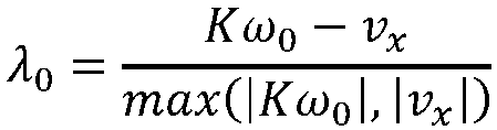
- Verfahren nach einem der vorherigen Ansprüche, wobei der Wellenschlupf definiert ist (S11) als
- Verfahren nach einem der vorherigen Ansprüche, wobei eine Beziehung zwischen dem Nenn-Wellenschlupf (λ0, 440) und der gewünschten Radkraft (Fx) durch ein inverses Reifenmodell (300) gegeben ist, wobei das Verfahren darin besteht, zunächst dieses inverse Reifenmodell zu erlangen (S12).
- Verfahren nach einem der vorherigen Ansprüche, umfassend ein Steuern (S41) der Wellendrehzahl (ω0) basierend auf dem Soll-Wellenschlupf (λT, 460) durch Einstellen der Wellendrehzahl (ω0), um den Soll-Wellenschlupf (λT, 460) zu erlangen.
- Verfahren nach einem der Ansprüche 1-10, umfassend ein Steuern (S42) der Wellendrehzahl (ω0) basierend auf dem Soll-Wellenschlupf (λT, 460) durch Einstellen der Wellendrehzahl (ω0), um unter dem Soll-Wellenschlupf (λT, 460) zu sein.
- Computerprogramm (1020), umfassend Programmcodeeinrichtungen zum Durchführen der Schritte nach einem der Ansprüche 1-12, wenn das Programm auf einem Computer oder auf einer Verarbeitungsschaltung (1010) einer Steuereinheit (130) ausgeführt wird.
- Computerlesbares Medium (1010), das ein Computerprogramm (1020) trägt, umfassend Programmcodeeinrichtungen zum Durchführen der Schritte nach einem der Ansprüche 1-12, wenn das Programmprodukt auf einem Computer oder auf einer Verarbeitungsschaltung (1010) einer Steuereinheit (130) ausgeführt wird.
- Steuereinheit (130), die zur Antriebssteuerung eines Schwerlastfahrzeugs (100) angeordnet ist, wobei das Schwerlastfahrzeug (100) eine Differentialantriebsanordnung (245) umfasst, die in Verbindung mit einer Antriebsachse (246) mit einem linken Rad (270) und einem rechten Rad (280) angeordnet ist, wobei die Steuereinheit eine Verarbeitungsschaltung (910) umfasst, die zu Folgendem konfiguriert istBestimmen eines Nenn-Wellenschlupfs (λ0, 440), der einer gewünschten Radkraft (Fx) entspricht, die von den Antriebsachsrädern (270, 280) erzeugt werden soll, wobei der Nenn-Wellenschlupf indikativ für eine Differenz zwischen einer aktuellen Fahrzeuggeschwindigkeit (vx ) und einer Fahrzeuggeschwindigkeit, die der Wellendrehzahl (ω0) entspricht, ist,Bestimmen einer Differenz zwischen einer Geschwindigkeit (ω1) des linken Rads und einer Geschwindigkeit (ω2) des rechten Rads,Einstellen des Nenn-Wellenschlupfs (λ0, 440) abhängig von einer Größe der Raddrehzahldifferenz zu einem Soll-Wellenschlupf (λT, 460),wobei der Soll-Wellenschlupf (λT, 460) um einen Betrag (450) kleiner ist als der Nenn-Radschlupf (λ0, 440), der abhängig von der Größe der Raddrehzahldifferenz bestimmt wird, und Steuern der Wellendrehzahl (ω0) basierend auf dem Soll-Wellenschlupf (λT, 460).
- Fahrzeug (100), umfassend eine Steuereinheit (800) nach Anspruch 15.
Applications Claiming Priority (1)
| Application Number | Priority Date | Filing Date | Title |
|---|---|---|---|
| PCT/EP2021/065973 WO2022262937A1 (en) | 2021-06-14 | 2021-06-14 | A method for controlling propulsion of a heavy-duty vehicle |
Publications (3)
| Publication Number | Publication Date |
|---|---|
| EP4355602A1 EP4355602A1 (de) | 2024-04-24 |
| EP4355602C0 EP4355602C0 (de) | 2025-06-11 |
| EP4355602B1 true EP4355602B1 (de) | 2025-06-11 |
Family
ID=76601194
Family Applications (1)
| Application Number | Title | Priority Date | Filing Date |
|---|---|---|---|
| EP21734296.3A Active EP4355602B1 (de) | 2021-06-14 | 2021-06-14 | Verfahren zur steuerung des antriebs eines schwerlastfahrzeugs |
Country Status (5)
| Country | Link |
|---|---|
| US (1) | US12208799B2 (de) |
| EP (1) | EP4355602B1 (de) |
| KR (1) | KR20240021803A (de) |
| CN (1) | CN117460638A (de) |
| WO (1) | WO2022262937A1 (de) |
Family Cites Families (9)
| Publication number | Priority date | Publication date | Assignee | Title |
|---|---|---|---|---|
| JP2004090886A (ja) | 2002-09-04 | 2004-03-25 | Advics:Kk | 車両のトラクション制御装置 |
| CN102320300B (zh) | 2008-12-26 | 2014-05-28 | 株式会社小松制作所 | 牵引力控制装置 |
| US9254748B2 (en) | 2013-02-01 | 2016-02-09 | Hondata, Inc. | Vehicle traction control |
| JP6241248B2 (ja) | 2013-12-11 | 2017-12-06 | スズキ株式会社 | 車両制御方法 |
| JP6219883B2 (ja) | 2015-05-22 | 2017-10-25 | 株式会社アドヴィックス | 車両用制御装置 |
| GB2562308B (en) | 2017-05-12 | 2022-10-26 | Arrival Ltd | Regenerative braking control system |
| EP3569436B1 (de) | 2018-05-17 | 2022-05-11 | Bayerische Motoren Werke Aktiengesellschaft | Traktionssteuerungssystem |
| SE542776C2 (en) | 2018-05-23 | 2020-07-07 | Scania Cv Ab | Control unit performing dynamic wheel slip target traction control |
| US11161514B2 (en) | 2019-09-12 | 2021-11-02 | Ford Global Technologies, Llc | System and method for coordinating independent axles for continuous wheel slip control |
-
2021
- 2021-06-14 WO PCT/EP2021/065973 patent/WO2022262937A1/en not_active Ceased
- 2021-06-14 KR KR1020237042965A patent/KR20240021803A/ko active Pending
- 2021-06-14 CN CN202180099171.2A patent/CN117460638A/zh active Pending
- 2021-06-14 US US18/569,547 patent/US12208799B2/en active Active
- 2021-06-14 EP EP21734296.3A patent/EP4355602B1/de active Active
Also Published As
| Publication number | Publication date |
|---|---|
| WO2022262937A1 (en) | 2022-12-22 |
| US20240286615A1 (en) | 2024-08-29 |
| EP4355602C0 (de) | 2025-06-11 |
| KR20240021803A (ko) | 2024-02-19 |
| CN117460638A (zh) | 2024-01-26 |
| US12208799B2 (en) | 2025-01-28 |
| EP4355602A1 (de) | 2024-04-24 |
Similar Documents
| Publication | Publication Date | Title |
|---|---|---|
| EP3851345B1 (de) | Radschlupfbasierte fahrzeugbewegungsverwaltung für schwerlastfahrzeuge | |
| EP4108529B1 (de) | Verfahren zur steuerung des antriebs eines nutzfahrzeugs | |
| US20230047444A1 (en) | Vehicle motion management based on torque request with speed limit | |
| EP4090548B1 (de) | Elektrische differenzialantriebsanordnung für schwerlastkraftwagen | |
| EP4140839B1 (de) | Fahrzeugsteuerung basierend auf einer dynamisch konfigurierten seitenschlupfgrenze | |
| EP4219252B1 (de) | Verfahren zur steuerung eines schwerlastfahrzeugs | |
| EP4190598B1 (de) | Redundante fahrzeugsteuerungssysteme auf der basis von reifensensoren - lastschätzung | |
| EP4330097B1 (de) | Fahrzeugsteuerung auf basis dynamisch konfigurierter längsradschlupfgrenzen | |
| EP4347302B1 (de) | Energieeffizienter antrieb auf basis eines radschlupfausgeglichenen antriebs | |
| EP4190651B1 (de) | Redundante fahrzeugsteuerungssysteme auf basis von reifensensoren | |
| EP4355602B1 (de) | Verfahren zur steuerung des antriebs eines schwerlastfahrzeugs | |
| KR20240069764A (ko) | 대형 차량을 위한 휠 슬립-기반 모션 제어 |
Legal Events
| Date | Code | Title | Description |
|---|---|---|---|
| STAA | Information on the status of an ep patent application or granted ep patent |
Free format text: STATUS: UNKNOWN |
|
| STAA | Information on the status of an ep patent application or granted ep patent |
Free format text: STATUS: THE INTERNATIONAL PUBLICATION HAS BEEN MADE |
|
| PUAI | Public reference made under article 153(3) epc to a published international application that has entered the european phase |
Free format text: ORIGINAL CODE: 0009012 |
|
| STAA | Information on the status of an ep patent application or granted ep patent |
Free format text: STATUS: REQUEST FOR EXAMINATION WAS MADE |
|
| 17P | Request for examination filed |
Effective date: 20231130 |
|
| AK | Designated contracting states |
Kind code of ref document: A1 Designated state(s): AL AT BE BG CH CY CZ DE DK EE ES FI FR GB GR HR HU IE IS IT LI LT LU LV MC MK MT NL NO PL PT RO RS SE SI SK SM TR |
|
| DAV | Request for validation of the european patent (deleted) | ||
| DAX | Request for extension of the european patent (deleted) | ||
| GRAP | Despatch of communication of intention to grant a patent |
Free format text: ORIGINAL CODE: EPIDOSNIGR1 |
|
| STAA | Information on the status of an ep patent application or granted ep patent |
Free format text: STATUS: GRANT OF PATENT IS INTENDED |
|
| INTG | Intention to grant announced |
Effective date: 20250204 |
|
| GRAS | Grant fee paid |
Free format text: ORIGINAL CODE: EPIDOSNIGR3 |
|
| GRAA | (expected) grant |
Free format text: ORIGINAL CODE: 0009210 |
|
| STAA | Information on the status of an ep patent application or granted ep patent |
Free format text: STATUS: THE PATENT HAS BEEN GRANTED |
|
| AK | Designated contracting states |
Kind code of ref document: B1 Designated state(s): AL AT BE BG CH CY CZ DE DK EE ES FI FR GB GR HR HU IE IS IT LI LT LU LV MC MK MT NL NO PL PT RO RS SE SI SK SM TR |
|
| REG | Reference to a national code |
Ref country code: GB Ref legal event code: FG4D |
|
| REG | Reference to a national code |
Ref country code: CH Ref legal event code: EP |
|
| REG | Reference to a national code |
Ref country code: IE Ref legal event code: FG4D |
|
| REG | Reference to a national code |
Ref country code: DE Ref legal event code: R096 Ref document number: 602021032134 Country of ref document: DE |
|
| U01 | Request for unitary effect filed |
Effective date: 20250613 |
|
| PGFP | Annual fee paid to national office [announced via postgrant information from national office to epo] |
Ref country code: AT Payment date: 20250721 Year of fee payment: 5 |
|
| U07 | Unitary effect registered |
Designated state(s): AT BE BG DE DK EE FI FR IT LT LU LV MT NL PT RO SE SI Effective date: 20250627 |
|
| U20 | Renewal fee for the european patent with unitary effect paid |
Year of fee payment: 5 Effective date: 20250624 |
|
| PG25 | Lapsed in a contracting state [announced via postgrant information from national office to epo] |
Ref country code: ES Free format text: LAPSE BECAUSE OF FAILURE TO SUBMIT A TRANSLATION OF THE DESCRIPTION OR TO PAY THE FEE WITHIN THE PRESCRIBED TIME-LIMIT Effective date: 20250611 |
|
| PG25 | Lapsed in a contracting state [announced via postgrant information from national office to epo] |
Ref country code: GR Free format text: LAPSE BECAUSE OF FAILURE TO SUBMIT A TRANSLATION OF THE DESCRIPTION OR TO PAY THE FEE WITHIN THE PRESCRIBED TIME-LIMIT Effective date: 20250912 Ref country code: NO Free format text: LAPSE BECAUSE OF FAILURE TO SUBMIT A TRANSLATION OF THE DESCRIPTION OR TO PAY THE FEE WITHIN THE PRESCRIBED TIME-LIMIT Effective date: 20250911 |
|
| PG25 | Lapsed in a contracting state [announced via postgrant information from national office to epo] |
Ref country code: HR Free format text: LAPSE BECAUSE OF FAILURE TO SUBMIT A TRANSLATION OF THE DESCRIPTION OR TO PAY THE FEE WITHIN THE PRESCRIBED TIME-LIMIT Effective date: 20250611 |
|
| PG25 | Lapsed in a contracting state [announced via postgrant information from national office to epo] |
Ref country code: RS Free format text: LAPSE BECAUSE OF FAILURE TO SUBMIT A TRANSLATION OF THE DESCRIPTION OR TO PAY THE FEE WITHIN THE PRESCRIBED TIME-LIMIT Effective date: 20250911 |