EP4355397B1 - Ventilatorsystem - Google Patents
Ventilatorsystem Download PDFInfo
- Publication number
- EP4355397B1 EP4355397B1 EP22726675.6A EP22726675A EP4355397B1 EP 4355397 B1 EP4355397 B1 EP 4355397B1 EP 22726675 A EP22726675 A EP 22726675A EP 4355397 B1 EP4355397 B1 EP 4355397B1
- Authority
- EP
- European Patent Office
- Prior art keywords
- ventilator
- controller
- nebulizer
- interface controller
- interface
- Prior art date
- Legal status (The legal status is an assumption and is not a legal conclusion. Google has not performed a legal analysis and makes no representation as to the accuracy of the status listed.)
- Active
Links
Images


Classifications
-
- A—HUMAN NECESSITIES
- A61—MEDICAL OR VETERINARY SCIENCE; HYGIENE
- A61M—DEVICES FOR INTRODUCING MEDIA INTO, OR ONTO, THE BODY; DEVICES FOR TRANSDUCING BODY MEDIA OR FOR TAKING MEDIA FROM THE BODY; DEVICES FOR PRODUCING OR ENDING SLEEP OR STUPOR
- A61M16/00—Devices for influencing the respiratory system of patients by gas treatment, e.g. ventilators; Tracheal tubes
- A61M16/021—Devices for influencing the respiratory system of patients by gas treatment, e.g. ventilators; Tracheal tubes operated by electrical means
- A61M16/022—Control means therefor
-
- A—HUMAN NECESSITIES
- A61—MEDICAL OR VETERINARY SCIENCE; HYGIENE
- A61M—DEVICES FOR INTRODUCING MEDIA INTO, OR ONTO, THE BODY; DEVICES FOR TRANSDUCING BODY MEDIA OR FOR TAKING MEDIA FROM THE BODY; DEVICES FOR PRODUCING OR ENDING SLEEP OR STUPOR
- A61M11/00—Sprayers or atomisers specially adapted for therapeutic purposes
- A61M11/005—Sprayers or atomisers specially adapted for therapeutic purposes using ultrasonics
-
- A—HUMAN NECESSITIES
- A61—MEDICAL OR VETERINARY SCIENCE; HYGIENE
- A61M—DEVICES FOR INTRODUCING MEDIA INTO, OR ONTO, THE BODY; DEVICES FOR TRANSDUCING BODY MEDIA OR FOR TAKING MEDIA FROM THE BODY; DEVICES FOR PRODUCING OR ENDING SLEEP OR STUPOR
- A61M2205/00—General characteristics of the apparatus
- A61M2205/35—Communication
- A61M2205/3576—Communication with non implanted data transmission devices, e.g. using external transmitter or receiver
- A61M2205/3584—Communication with non implanted data transmission devices, e.g. using external transmitter or receiver using modem, internet or Bluetooth®
-
- A—HUMAN NECESSITIES
- A61—MEDICAL OR VETERINARY SCIENCE; HYGIENE
- A61M—DEVICES FOR INTRODUCING MEDIA INTO, OR ONTO, THE BODY; DEVICES FOR TRANSDUCING BODY MEDIA OR FOR TAKING MEDIA FROM THE BODY; DEVICES FOR PRODUCING OR ENDING SLEEP OR STUPOR
- A61M2205/00—General characteristics of the apparatus
- A61M2205/60—General characteristics of the apparatus with identification means
- A61M2205/6018—General characteristics of the apparatus with identification means providing set-up signals for the apparatus configuration
Definitions
- the present invention relates to ventilator systems with aerosol treatment.
- US2005/0217666A describes a method of treating a patient with a pulmonary disease, including delivering a dose of aerosolized medicament intermittently to a ventilator circuit coupled to the respiratory system of the patient.
- a controller coupled to an aerosol generator is operable in that an on/off operation of the aerosol is triggered by the controller receiving an external signal, such as a signal from the ventilator, which can correspond to the point in the ventilator's cycle of that is the start of an inhalation phase in which the ventilator begins to push inspiratory air into the ventilator circuit.
- An object of the invention is to achieve enhanced versatility in control of nebulizer operation for treatment including both ventilation and aerosol therapy.
- the invention provides a ventilator system as set out in claims 1 to 9, a method of operating a ventilator system as set out in claims 10 to 14, and a non-transitory storage medium as set out in claim 15.
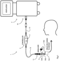
- a ventilator system 1 comprises a ventilator 2 and a nebulizer 3 which at the physical level is of the type marketed by Aerogen TM under the trademark Solo TM . Both the ventilator and the nebulizer incorporate digital controllers as is known in the art. An example of the nebulizer head is described in our previous PCT application WO2012/046220 .
- the nebulizer 3 comprises a vibratable aperture plate, and a piezoelectric vibration generator mounted to a support washer.
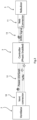
- the system 1 also comprises an interface 4 between the ventilator 2 and the nebulizer 3, shown in more detail in Fig. 2 .
- the interface 4 is wired, with the following.
- the cable 13 transmits nebulizer drive signals, and the cable 12 transmits control signals bi-directionally and also transmits power from the ventilator 2 controller.
- the system 1 operates with the ventilator 2 and the nebulizer 3 operating in synchronism for optimum patient treatment.
- the interface controller 5 comprises a boost circuit with a high frequency, high efficiency DC-to-DC converter with an integrated power switch capable of providing an output voltage and current profile suitable to drive the nebulizer load.
- a drive circuit utilizing a series inductor to generate alternating AC voltage.
- the drive circuit includes a high speed MOSFET driver controlled by a pulse width modulated signal from the microcontroller.
- a microcontroller with an integrated peripheral module that can automatically change clock sources and power levels according to signals received from the ventilator controller. The latter provides power and control signals via the cable 12.
- the interface controller 5 interprets signals from the ventilator to provide signals on the cable 13 for control of the nebulizer aperture plate.
- the controller 5 and the nebulizer 3 require no more than 500 mA at nominal 5V to generate a desired aerosol.
- the nebulizer drive circuit has components to generate an output sine waveform of approximately 100V AC, causing aerosol to be generated. It uses inputs from the interface controller 5 microcontroller and the boost circuit 10 to achieve its output.
- the interface controller 5 drive circuit is matched to the impedance of a piezoelectric vibration generator.
- the microcontroller of the interface controller 5 generates a square waveform of 120 to 150 kHz which is sent to the drive circuit coupler 11, and it has a boost circuit which generates a nominal 9V to 12V, nominal 9.5V, voltage required by the interface controller 5 from an input within the range of 4.75V to 5.25 V DC.
- a drive frequency of 120 kHz to 150 kHz is generated to drive the aperture plate at close to its resonant frequency so that enough amplitude is generated to break off droplets and produce the aerosol.
- the aerosol generator 3(b) may be calibrated at a certain pulse rate by measuring how long it takes to deliver a known quantity of liquid medication. There is a linear relationship between the pulse rate and the nebulizer flow rate, allowing accurate control over the delivery rate.
- the interface controller 5, using signals from the ventilator 2, can achieve very wide-ranging control of the nebulizer 3.
- the interface controller 5 can upload in various embodiments some or all of the following nebulizer characteristics to the host ventilator controller: power consumption, wet/dry state, nebulizer disconnect status, cable disconnect status, error or fault states, nebulization duration, and time of nebulization.
- the ventilator controller can in various embodiments provide one or more of the following instructions to the interface controller 5: nebulization start/stop, nebulization time, nebulization flow rate, nebulization pulse rate, inspiratory/expiratory signal to enable phased nebulization.
- the interface controller 5 may operate as a slave device, with a dosing regime determined by the ventilator controller. This allows comprehensive control and treatment monitoring for a wide variety of situations such as in the home or in hospitals. Because the controller is essentially part of the cabling it may not be by-passed accidentally.
- a state diagram illustrates the states for operation of the interface controller 5:
- the Nebulization State ends if there is no command from the coupler 10 for a timeout period of, in one example, 5s.
- the time-out period of 5 seconds is implemented in software and is restarted each time a valid command from the ventilator 2 is received. Delivery is suspended if a valid Start command is not received within the timeout period and the controller will revert to the initialized state. This feature prevents in delivery of medication, in the case where the ventilator fails to communicate with the controller
- the nebulizer 3 is external to the ventilator 2 but yet can be controlled by the ventilator.
- the interface 4 has the ability to communicate and exchange information with the ventilator 2 to allow phasic delivery, and the display of nebulizer operation information on the ventilator.
- the interface controller 5 operates external to the ventilator 2, while allowing full control by the ventilator GUI (graphical user interface), solving the issue of restricted space within the ventilator.
- the interface 4 provides multiple communication methods to allow flexibility of operation from multiple ventilator/manufacturers.
- the aerosol delivery device can function with three different types of communication methods, such as full RS232, vendor-specific UART, or Logic level Enable/fault, using a standard command protocol.
- Phasic operation by a ventilator of the nebulizer is communicated to the nebulizer 3. Also, the interface controller 5 performs recognition of approved nebulizer types and prevention of use of third party non-approved nebulizers
- the interface 4 allows a generic communication protocol to be developed, allowing more versatile use of nebulizers with different types of ventilator. In addition to continuation of drug delivery, it is also crucial that the operational commands (On/Off/Status requests) remain functioning.
- the interface 4 detects the type of nebulizer attached and only operates with allowed nebulizer types according to its configuration.
- the controller may chop the frequency such that aerosol is generated for a short time and then stopped for a short time this gives good control of the nebulizer's flow rate. This lower frequency is called the "pulse rate”.
- the drive frequency may be started and stopped as required using the microcontroller interface controller 5, allowing for control of flow rate by driving the aerosol generator 3(b) for any required pulse rate.
Landscapes
- Health & Medical Sciences (AREA)
- Life Sciences & Earth Sciences (AREA)
- General Health & Medical Sciences (AREA)
- Biomedical Technology (AREA)
- Heart & Thoracic Surgery (AREA)
- Hematology (AREA)
- Engineering & Computer Science (AREA)
- Animal Behavior & Ethology (AREA)
- Anesthesiology (AREA)
- Public Health (AREA)
- Veterinary Medicine (AREA)
- Emergency Medicine (AREA)
- Pulmonology (AREA)
- Nozzles (AREA)
- Infusion, Injection, And Reservoir Apparatuses (AREA)
Claims (9)
- Beatmungssystem (1), das ein Beatmungsgerät (2), einen Vernebler (3) und eine Schnittstelle (4) umfasst, die eine Steuerung (5) umfasst und das Beatmungsgerät auf eine Weise mit dem Vernebler verbindet, welche ein Steuern von zumindest einigen Operationen des Verneblers über die Beatmungsgerätsteuerung ermöglicht,wobei die Schnittstelle (4) ein Kupplungsstück (10) für das Beatmungsgerät (2), ein das Kupplungsstück mit der Schnittstellensteuerung (5) verbindendes Kabel (12) und ein die Schnittstellensteuerung (5) mit einem Kupplungsstück (11) verbindendes Kabel zum Anstecken an den Vernebler (3) umfasst,wobei die Schnittstellensteuerung (5) so konfiguriert ist, dass sie von dem Beatmungsgerät mit Strom versorgt wird und diesen zum Antreiben des Verneblers benutzt,wobei die Schnittstellensteuerung (5) so konfiguriert ist, dass sie auf Befehle aus dem Beatmungsgerät hin eine phasische Abgabesteuerung des Verneblers durchführt,wobei die Schnittstellensteuerung (5) so konfiguriert ist, dass sie eine Zeitlimitüberwachung umsetzt, bei der sie einen Befehl generiert, die Verneblung einzustellen, wenn vor Ablauf eines Zeitlimits kein Startbefehl aus der Beatmungsgerätsteuerung empfangen wurde,wobei die Schnittstellensteuerung (5) so konfiguriert ist, dass sie jedesmal, wenn ein gültiger Startbefehl aus der Beatmungsgerätsteuerung empfangen wird, einen Verneblungsneustart-Befehl generiert,wobei die Schnittstellensteuerung so konfiguriert ist, dass sie als Slave-Vorrichtung mit einem Dosiermodell arbeitet, das von der Beatmungsgerätsteuerung bestimmt wird.
- Beatmungssystem nach Anspruch 1, wobei die Schnittstellensteuerung (5) so konfiguriert ist, dass sie mit mehreren Zuständen arbeitet, die Befehlen aus dem Beatmungsgerät entsprechend durchlaufen werden.
- Beatmungssystem nach Anspruch 2, wobei zu den Befehlen Befehle für einen Einschaltzustand, einen initialisierten Zustand und einen Verneblungszustand gehören.
- Beatmungssystem nach Anspruch 3, wobei die Schnittstellensteuerung so konfiguriert ist, dass sie bei Ablauf eines Zeitlimits automatisch aus dem Verneblungszustand wechselt.
- Beatmungssystem nach einem der Ansprüche 1 bis 4, wobei die
Schnittstellensteuerung (5) so konfiguriert ist, dass sie entsprechend einem beliebigen von mehreren Protokollen mit dem Beatmungsgerät kommuniziert. - Beatmungssystem nach einem der Ansprüche 1 bis 5, bei dem die
Schnittstellensteuerung so konfiguriert ist, dass sie einen Befehl generiert, die Verneblung zu unterbrechen, wenn innerhalb des Zeitlimits, in dem die Schnittstellensteuerung in einen initialisierten Zustand zurückkehrt, kein gültiger Startbefehl empfangen wird. - Beatmungssystem nach einem der Ansprüche 1 bis 6, bei dem der Vernebler (3) einen Aerosolgenerator (3b) mit einer Lochplatte umfasst, die mit einer Antriebsfrequenz von 120 kHz bis 150 kHz vibriert.
- Beatmungssystem nach Anspruch 7, bei dem die Steuerung so konfiguriert ist, dass sie zum Steuern der Aerosolgeneratordurchflussrate eine Antriebsfrequenz des Aerosolgenerators (3(b)) mit einer Pulsrate zerhackt.
- Beatmungssystem nach einem der Ansprüche 7 oder 8, bei dem das System ferner Folgendes umfasst:- einen Mikrocontroller mit einem integrierten Peripheriemodul, das so konfiguriert ist, dass es aus der Beatmungsgerätsteuerung empfangenen Signalen entsprechend automatisch Taktquellen und Leistungspegel ändert und über ein Kabel (12) Leistungs- und Steuersignale bereitstellt, und- eine Antriebsschaltung, die so konfiguriert ist, dass sie eine in Reihe geschaltete Induktionsspule zum Erzeugen einer Wechselspannung benutzt, wobei die Antriebsschaltung einen schnellen MOSFET-Treiber umfasst, der über ein pulsbreitenmoduliertes Signal aus dem Mikrocontroller gesteuert wird.
Applications Claiming Priority (2)
| Application Number | Priority Date | Filing Date | Title |
|---|---|---|---|
| EP21179828 | 2021-06-16 | ||
| PCT/EP2022/061596 WO2022263049A1 (en) | 2021-06-16 | 2022-04-29 | A ventilator system |
Publications (3)
| Publication Number | Publication Date |
|---|---|
| EP4355397A1 EP4355397A1 (de) | 2024-04-24 |
| EP4355397C0 EP4355397C0 (de) | 2025-06-25 |
| EP4355397B1 true EP4355397B1 (de) | 2025-06-25 |
Family
ID=76942704
Family Applications (1)
| Application Number | Title | Priority Date | Filing Date |
|---|---|---|---|
| EP22726675.6A Active EP4355397B1 (de) | 2021-06-16 | 2022-04-29 | Ventilatorsystem |
Country Status (2)
| Country | Link |
|---|---|
| EP (1) | EP4355397B1 (de) |
| WO (1) | WO2022263049A1 (de) |
Family Cites Families (7)
| Publication number | Priority date | Publication date | Assignee | Title |
|---|---|---|---|---|
| US8336545B2 (en) * | 2000-05-05 | 2012-12-25 | Novartis Pharma Ag | Methods and systems for operating an aerosol generator |
| US7971588B2 (en) * | 2000-05-05 | 2011-07-05 | Novartis Ag | Methods and systems for operating an aerosol generator |
| EP2274034A1 (de) * | 2008-03-28 | 2011-01-19 | Stamford Devices Limited | Insufflation von körperhöhlen |
| CA2811423C (en) * | 2010-09-30 | 2019-03-12 | Breathe Technologies, Inc. | Methods, systems and devices for humidifying a respiratory tract |
| NO3181243T3 (de) | 2010-10-04 | 2018-08-11 | ||
| US10029053B2 (en) * | 2012-05-03 | 2018-07-24 | Stamford Devices Ltd. | Nebulizer |
| EP3452150B1 (de) * | 2016-05-03 | 2024-01-17 | Pneuma Respiratory, Inc. | Tröpfchenausgabevorrichtung zur ausgabe von flüssigkeiten an das lungensystem |
-
2022
- 2022-04-29 EP EP22726675.6A patent/EP4355397B1/de active Active
- 2022-04-29 WO PCT/EP2022/061596 patent/WO2022263049A1/en not_active Ceased
Also Published As
| Publication number | Publication date |
|---|---|
| EP4355397C0 (de) | 2025-06-25 |
| EP4355397A1 (de) | 2024-04-24 |
| WO2022263049A1 (en) | 2022-12-22 |
Similar Documents
| Publication | Publication Date | Title |
|---|---|---|
| US20260115391A1 (en) | Nebulizer | |
| AU2021201720B2 (en) | Systems and methods for producing and delivering ultrasonic therapies for wound treatment and healing | |
| US20100326431A1 (en) | Aerosolization Device | |
| TWI609706B (zh) | 霧化系統、霧化器及其驅動方法 | |
| EP4355397B1 (de) | Ventilatorsystem | |
| US10118190B2 (en) | Scent dispensing apparatus and method for the control thereof | |
| CN210409159U (zh) | 一种雾化装置 | |
| TWI631993B (zh) | 霧化裝置及其操作方法 | |
| CN217014957U (zh) | 雾化器控制装置和雾化器 | |
| TW201121658A (en) | Driving control circuit of atomizing device and driving control method thereof | |
| CN119587814A (zh) | 一种基于呼吸机的雾化控制方法及系统 | |
| CN215194646U (zh) | 一种盐溶胶生成装置 | |
| WO2024018656A1 (ja) | ネブライザシステム | |
| CN119215276A (zh) | 携式雾化器以及便携式雾化器的关机方法 | |
| CN120529930A (zh) | 具有高剂量置信度模式的液滴输送装置 | |
| CN105763098A (zh) | 一种通过自动补偿提供电力恒定的方法及其雾化模块 | |
| CN117205408A (zh) | 无线智能控制的直流驱动型雾化器 |
Legal Events
| Date | Code | Title | Description |
|---|---|---|---|
| STAA | Information on the status of an ep patent application or granted ep patent |
Free format text: STATUS: UNKNOWN |
|
| STAA | Information on the status of an ep patent application or granted ep patent |
Free format text: STATUS: THE INTERNATIONAL PUBLICATION HAS BEEN MADE |
|
| PUAI | Public reference made under article 153(3) epc to a published international application that has entered the european phase |
Free format text: ORIGINAL CODE: 0009012 |
|
| STAA | Information on the status of an ep patent application or granted ep patent |
Free format text: STATUS: REQUEST FOR EXAMINATION WAS MADE |
|
| 17P | Request for examination filed |
Effective date: 20240103 |
|
| AK | Designated contracting states |
Kind code of ref document: A1 Designated state(s): AL AT BE BG CH CY CZ DE DK EE ES FI FR GB GR HR HU IE IS IT LI LT LU LV MC MK MT NL NO PL PT RO RS SE SI SK SM TR |
|
| DAV | Request for validation of the european patent (deleted) | ||
| DAX | Request for extension of the european patent (deleted) | ||
| GRAP | Despatch of communication of intention to grant a patent |
Free format text: ORIGINAL CODE: EPIDOSNIGR1 |
|
| STAA | Information on the status of an ep patent application or granted ep patent |
Free format text: STATUS: GRANT OF PATENT IS INTENDED |
|
| INTG | Intention to grant announced |
Effective date: 20250410 |
|
| GRAS | Grant fee paid |
Free format text: ORIGINAL CODE: EPIDOSNIGR3 |
|
| GRAA | (expected) grant |
Free format text: ORIGINAL CODE: 0009210 |
|
| STAA | Information on the status of an ep patent application or granted ep patent |
Free format text: STATUS: THE PATENT HAS BEEN GRANTED |
|
| AK | Designated contracting states |
Kind code of ref document: B1 Designated state(s): AL AT BE BG CH CY CZ DE DK EE ES FI FR GB GR HR HU IE IS IT LI LT LU LV MC MK MT NL NO PL PT RO RS SE SI SK SM TR |
|
| REG | Reference to a national code |
Ref country code: GB Ref legal event code: FG4D |
|
| REG | Reference to a national code |
Ref country code: CH Ref legal event code: EP |
|
| REG | Reference to a national code |
Ref country code: CH Ref legal event code: EP |
|
| REG | Reference to a national code |
Ref country code: IE Ref legal event code: FG4D |
|
| U01 | Request for unitary effect filed |
Effective date: 20250625 |
|
| U07 | Unitary effect registered |
Designated state(s): AT BE BG DE DK EE FI FR IT LT LU LV MT NL PT RO SE SI Effective date: 20250701 |
|
| PG25 | Lapsed in a contracting state [announced via postgrant information from national office to epo] |
Ref country code: NO Free format text: LAPSE BECAUSE OF FAILURE TO SUBMIT A TRANSLATION OF THE DESCRIPTION OR TO PAY THE FEE WITHIN THE PRESCRIBED TIME-LIMIT Effective date: 20250925 Ref country code: GR Free format text: LAPSE BECAUSE OF FAILURE TO SUBMIT A TRANSLATION OF THE DESCRIPTION OR TO PAY THE FEE WITHIN THE PRESCRIBED TIME-LIMIT Effective date: 20250926 |
|
| PG25 | Lapsed in a contracting state [announced via postgrant information from national office to epo] |
Ref country code: HR Free format text: LAPSE BECAUSE OF FAILURE TO SUBMIT A TRANSLATION OF THE DESCRIPTION OR TO PAY THE FEE WITHIN THE PRESCRIBED TIME-LIMIT Effective date: 20250625 |
|
| PG25 | Lapsed in a contracting state [announced via postgrant information from national office to epo] |
Ref country code: RS Free format text: LAPSE BECAUSE OF FAILURE TO SUBMIT A TRANSLATION OF THE DESCRIPTION OR TO PAY THE FEE WITHIN THE PRESCRIBED TIME-LIMIT Effective date: 20250925 |
|
| PG25 | Lapsed in a contracting state [announced via postgrant information from national office to epo] |
Ref country code: IS Free format text: LAPSE BECAUSE OF FAILURE TO SUBMIT A TRANSLATION OF THE DESCRIPTION OR TO PAY THE FEE WITHIN THE PRESCRIBED TIME-LIMIT Effective date: 20251025 |
|
| PG25 | Lapsed in a contracting state [announced via postgrant information from national office to epo] |
Ref country code: SM Free format text: LAPSE BECAUSE OF FAILURE TO SUBMIT A TRANSLATION OF THE DESCRIPTION OR TO PAY THE FEE WITHIN THE PRESCRIBED TIME-LIMIT Effective date: 20250625 |
|
| PG25 | Lapsed in a contracting state [announced via postgrant information from national office to epo] |
Ref country code: CZ Free format text: LAPSE BECAUSE OF FAILURE TO SUBMIT A TRANSLATION OF THE DESCRIPTION OR TO PAY THE FEE WITHIN THE PRESCRIBED TIME-LIMIT Effective date: 20250625 |
|
| PG25 | Lapsed in a contracting state [announced via postgrant information from national office to epo] |
Ref country code: PL Free format text: LAPSE BECAUSE OF FAILURE TO SUBMIT A TRANSLATION OF THE DESCRIPTION OR TO PAY THE FEE WITHIN THE PRESCRIBED TIME-LIMIT Effective date: 20250625 |
|
| PG25 | Lapsed in a contracting state [announced via postgrant information from national office to epo] |
Ref country code: SK Free format text: LAPSE BECAUSE OF FAILURE TO SUBMIT A TRANSLATION OF THE DESCRIPTION OR TO PAY THE FEE WITHIN THE PRESCRIBED TIME-LIMIT Effective date: 20250625 |
|
| PG25 | Lapsed in a contracting state [announced via postgrant information from national office to epo] |
Ref country code: ES Free format text: LAPSE BECAUSE OF FAILURE TO SUBMIT A TRANSLATION OF THE DESCRIPTION OR TO PAY THE FEE WITHIN THE PRESCRIBED TIME-LIMIT Effective date: 20250625 |
|
| U20 | Renewal fee for the european patent with unitary effect paid |
Year of fee payment: 5 Effective date: 20260212 |
|
| PGFP | Annual fee paid to national office [announced via postgrant information from national office to epo] |
Ref country code: GB Payment date: 20260212 Year of fee payment: 5 |
|
| PGFP | Annual fee paid to national office [announced via postgrant information from national office to epo] |
Ref country code: IE Payment date: 20260212 Year of fee payment: 5 |
|
| PLBE | No opposition filed within time limit |
Free format text: ORIGINAL CODE: 0009261 |
|
| STAA | Information on the status of an ep patent application or granted ep patent |
Free format text: STATUS: NO OPPOSITION FILED WITHIN TIME LIMIT |