EP4354703A1 - Verfahren und vorrichtung zur erzielung von kompatibilität zwischen profilen in einem system zur drahtlosen stromübertragung - Google Patents
Verfahren und vorrichtung zur erzielung von kompatibilität zwischen profilen in einem system zur drahtlosen stromübertragung Download PDFInfo
- Publication number
- EP4354703A1 EP4354703A1 EP22833724.2A EP22833724A EP4354703A1 EP 4354703 A1 EP4354703 A1 EP 4354703A1 EP 22833724 A EP22833724 A EP 22833724A EP 4354703 A1 EP4354703 A1 EP 4354703A1
- Authority
- EP
- European Patent Office
- Prior art keywords
- wireless power
- mpp
- power receiver
- packet
- power transmitter
- Prior art date
- Legal status (The legal status is an assumption and is not a legal conclusion. Google has not performed a legal analysis and makes no representation as to the accuracy of the status listed.)
- Pending
Links
- 238000000034 method Methods 0.000 title claims abstract description 143
- 230000005540 biological transmission Effects 0.000 title abstract description 38
- 230000004044 response Effects 0.000 claims abstract description 86
- 230000006854 communication Effects 0.000 claims description 178
- 238000004891 communication Methods 0.000 claims description 178
- 238000012546 transfer Methods 0.000 claims description 143
- 230000008859 change Effects 0.000 claims description 6
- 108091006146 Channels Proteins 0.000 description 47
- 230000006870 function Effects 0.000 description 25
- 238000010586 diagram Methods 0.000 description 19
- 230000000694 effects Effects 0.000 description 15
- 230000006698 induction Effects 0.000 description 15
- 230000000977 initiatory effect Effects 0.000 description 14
- 239000003999 initiator Substances 0.000 description 9
- 238000001914 filtration Methods 0.000 description 8
- 238000001646 magnetic resonance method Methods 0.000 description 8
- 230000008569 process Effects 0.000 description 7
- 238000005516 engineering process Methods 0.000 description 6
- 238000012545 processing Methods 0.000 description 6
- 230000007704 transition Effects 0.000 description 6
- 238000012790 confirmation Methods 0.000 description 5
- 230000008878 coupling Effects 0.000 description 5
- 238000010168 coupling process Methods 0.000 description 5
- 238000005859 coupling reaction Methods 0.000 description 5
- 230000006978 adaptation Effects 0.000 description 4
- 238000006243 chemical reaction Methods 0.000 description 4
- 239000002184 metal Substances 0.000 description 4
- 229910052751 metal Inorganic materials 0.000 description 4
- 238000013461 design Methods 0.000 description 3
- 238000005259 measurement Methods 0.000 description 3
- 230000000153 supplemental effect Effects 0.000 description 3
- 230000001360 synchronised effect Effects 0.000 description 3
- 101000741965 Homo sapiens Inactive tyrosine-protein kinase PRAG1 Proteins 0.000 description 2
- 102100038659 Inactive tyrosine-protein kinase PRAG1 Human genes 0.000 description 2
- 230000004913 activation Effects 0.000 description 2
- 230000006399 behavior Effects 0.000 description 2
- 230000007175 bidirectional communication Effects 0.000 description 2
- 230000002457 bidirectional effect Effects 0.000 description 2
- 239000003990 capacitor Substances 0.000 description 2
- 238000012937 correction Methods 0.000 description 2
- 238000001514 detection method Methods 0.000 description 2
- 230000005672 electromagnetic field Effects 0.000 description 2
- CPTNXTSDQJQEFA-ZKOWQLKRSA-N mastoparan-A Chemical compound C1=CC=C2C(C[C@H](NC(=O)[C@H](CCCCN)NC(=O)[C@@H](N)[C@@H](C)CC)C(=O)N[C@@H](CCCCN)C(=O)N[C@@H](C)C(=O)N[C@@H]([C@@H](C)CC)C(=O)N[C@@H](CC(C)C)C(=O)N[C@@H](CC(O)=O)C(=O)N[C@@H](C)C(=O)N[C@@H](C(C)C)C(=O)N[C@@H](CCCCN)C(=O)N[C@@H](CCCCN)C(=O)N[C@@H](C(C)C)C(=O)N[C@@H]([C@@H](C)CC)C(N)=O)=CNC2=C1 CPTNXTSDQJQEFA-ZKOWQLKRSA-N 0.000 description 2
- NSFBOCKFBVQQKB-CQWNSWRRSA-N mastoparan-B Chemical compound C1=CC=C2C(C[C@H](NC(=O)[C@H](CO)NC(=O)[C@H](C(C)C)NC(=O)[C@@H](NC(=O)[C@H](CO)NC(=O)[C@H](CCCCN)NC(=O)[C@H](CC(C)C)NC(=O)[C@H](CCCCN)NC(=O)[C@@H](N)CC(C)C)[C@@H](C)CC)C(=O)N[C@@H](C)C(=O)N[C@@H](CCCCN)C(=O)N[C@@H](CCCCN)C(=O)N[C@@H](C(C)C)C(=O)N[C@@H](CC(C)C)C(N)=O)=CNC2=C1 NSFBOCKFBVQQKB-CQWNSWRRSA-N 0.000 description 2
- 230000010363 phase shift Effects 0.000 description 2
- 238000002604 ultrasonography Methods 0.000 description 2
- 238000004804 winding Methods 0.000 description 2
- 229910000859 α-Fe Inorganic materials 0.000 description 2
- RYGMFSIKBFXOCR-UHFFFAOYSA-N Copper Chemical compound [Cu] RYGMFSIKBFXOCR-UHFFFAOYSA-N 0.000 description 1
- 240000007594 Oryza sativa Species 0.000 description 1
- 235000007164 Oryza sativa Nutrition 0.000 description 1
- 238000013459 approach Methods 0.000 description 1
- 230000015572 biosynthetic process Effects 0.000 description 1
- 230000001413 cellular effect Effects 0.000 description 1
- 239000004020 conductor Substances 0.000 description 1
- 238000010276 construction Methods 0.000 description 1
- 238000001816 cooling Methods 0.000 description 1
- 230000001419 dependent effect Effects 0.000 description 1
- 230000005684 electric field Effects 0.000 description 1
- 230000004907 flux Effects 0.000 description 1
- 239000000446 fuel Substances 0.000 description 1
- 239000011521 glass Substances 0.000 description 1
- 239000000463 material Substances 0.000 description 1
- 150000002739 metals Chemical class 0.000 description 1
- 235000009566 rice Nutrition 0.000 description 1
- 230000011218 segmentation Effects 0.000 description 1
- 230000011664 signaling Effects 0.000 description 1
- 239000004984 smart glass Substances 0.000 description 1
- 230000003068 static effect Effects 0.000 description 1
- 238000012360 testing method Methods 0.000 description 1
- 230000002618 waking effect Effects 0.000 description 1
Images


Classifications
-
- H—ELECTRICITY
- H04—ELECTRIC COMMUNICATION TECHNIQUE
- H04L—TRANSMISSION OF DIGITAL INFORMATION, e.g. TELEGRAPHIC COMMUNICATION
- H04L67/00—Network arrangements or protocols for supporting network services or applications
- H04L67/50—Network services
- H04L67/55—Push-based network services
-
- H—ELECTRICITY
- H02—GENERATION; CONVERSION OR DISTRIBUTION OF ELECTRIC POWER
- H02J—CIRCUIT ARRANGEMENTS OR SYSTEMS FOR SUPPLYING OR DISTRIBUTING ELECTRIC POWER; SYSTEMS FOR STORING ELECTRIC ENERGY
- H02J50/00—Circuit arrangements or systems for wireless supply or distribution of electric power
- H02J50/80—Circuit arrangements or systems for wireless supply or distribution of electric power involving the exchange of data, concerning supply or distribution of electric power, between transmitting devices and receiving devices
-
- H—ELECTRICITY
- H04—ELECTRIC COMMUNICATION TECHNIQUE
- H04L—TRANSMISSION OF DIGITAL INFORMATION, e.g. TELEGRAPHIC COMMUNICATION
- H04L69/00—Network arrangements, protocols or services independent of the application payload and not provided for in the other groups of this subclass
- H04L69/24—Negotiation of communication capabilities
-
- H—ELECTRICITY
- H02—GENERATION; CONVERSION OR DISTRIBUTION OF ELECTRIC POWER
- H02J—CIRCUIT ARRANGEMENTS OR SYSTEMS FOR SUPPLYING OR DISTRIBUTING ELECTRIC POWER; SYSTEMS FOR STORING ELECTRIC ENERGY
- H02J50/00—Circuit arrangements or systems for wireless supply or distribution of electric power
- H02J50/10—Circuit arrangements or systems for wireless supply or distribution of electric power using inductive coupling
- H02J50/12—Circuit arrangements or systems for wireless supply or distribution of electric power using inductive coupling of the resonant type
-
- H—ELECTRICITY
- H02—GENERATION; CONVERSION OR DISTRIBUTION OF ELECTRIC POWER
- H02J—CIRCUIT ARRANGEMENTS OR SYSTEMS FOR SUPPLYING OR DISTRIBUTING ELECTRIC POWER; SYSTEMS FOR STORING ELECTRIC ENERGY
- H02J50/00—Circuit arrangements or systems for wireless supply or distribution of electric power
- H02J50/60—Circuit arrangements or systems for wireless supply or distribution of electric power responsive to the presence of foreign objects, e.g. detection of living beings
-
- H—ELECTRICITY
- H02—GENERATION; CONVERSION OR DISTRIBUTION OF ELECTRIC POWER
- H02J—CIRCUIT ARRANGEMENTS OR SYSTEMS FOR SUPPLYING OR DISTRIBUTING ELECTRIC POWER; SYSTEMS FOR STORING ELECTRIC ENERGY
- H02J7/00—Circuit arrangements for charging or depolarising batteries or for supplying loads from batteries
- H02J7/00032—Circuit arrangements for charging or depolarising batteries or for supplying loads from batteries characterised by data exchange
- H02J7/00034—Charger exchanging data with an electronic device, i.e. telephone, whose internal battery is under charge
-
- H—ELECTRICITY
- H02—GENERATION; CONVERSION OR DISTRIBUTION OF ELECTRIC POWER
- H02J—CIRCUIT ARRANGEMENTS OR SYSTEMS FOR SUPPLYING OR DISTRIBUTING ELECTRIC POWER; SYSTEMS FOR STORING ELECTRIC ENERGY
- H02J7/00—Circuit arrangements for charging or depolarising batteries or for supplying loads from batteries
- H02J7/00032—Circuit arrangements for charging or depolarising batteries or for supplying loads from batteries characterised by data exchange
- H02J7/00045—Authentication, i.e. circuits for checking compatibility between one component, e.g. a battery or a battery charger, and another component, e.g. a power source
-
- H—ELECTRICITY
- H04—ELECTRIC COMMUNICATION TECHNIQUE
- H04L—TRANSMISSION OF DIGITAL INFORMATION, e.g. TELEGRAPHIC COMMUNICATION
- H04L1/00—Arrangements for detecting or preventing errors in the information received
- H04L1/12—Arrangements for detecting or preventing errors in the information received by using return channel
- H04L1/16—Arrangements for detecting or preventing errors in the information received by using return channel in which the return channel carries supervisory signals, e.g. repetition request signals
- H04L1/1607—Details of the supervisory signal
- H04L1/1614—Details of the supervisory signal using bitmaps
-
- H—ELECTRICITY
- H04—ELECTRIC COMMUNICATION TECHNIQUE
- H04L—TRANSMISSION OF DIGITAL INFORMATION, e.g. TELEGRAPHIC COMMUNICATION
- H04L5/00—Arrangements affording multiple use of the transmission path
- H04L5/003—Arrangements for allocating sub-channels of the transmission path
- H04L5/0053—Allocation of signaling, i.e. of overhead other than pilot signals
- H04L5/0055—Physical resource allocation for ACK/NACK
-
- H—ELECTRICITY
- H04—ELECTRIC COMMUNICATION TECHNIQUE
- H04L—TRANSMISSION OF DIGITAL INFORMATION, e.g. TELEGRAPHIC COMMUNICATION
- H04L67/00—Network arrangements or protocols for supporting network services or applications
- H04L67/2866—Architectures; Arrangements
- H04L67/30—Profiles
-
- H—ELECTRICITY
- H04—ELECTRIC COMMUNICATION TECHNIQUE
- H04L—TRANSMISSION OF DIGITAL INFORMATION, e.g. TELEGRAPHIC COMMUNICATION
- H04L69/00—Network arrangements, protocols or services independent of the application payload and not provided for in the other groups of this subclass
- H04L69/22—Parsing or analysis of headers
-
- H—ELECTRICITY
- H04—ELECTRIC COMMUNICATION TECHNIQUE
- H04L—TRANSMISSION OF DIGITAL INFORMATION, e.g. TELEGRAPHIC COMMUNICATION
- H04L1/00—Arrangements for detecting or preventing errors in the information received
- H04L1/12—Arrangements for detecting or preventing errors in the information received by using return channel
- H04L1/16—Arrangements for detecting or preventing errors in the information received by using return channel in which the return channel carries supervisory signals, e.g. repetition request signals
- H04L1/1607—Details of the supervisory signal
- H04L1/1671—Details of the supervisory signal the supervisory signal being transmitted together with control information
-
- H—ELECTRICITY
- H04—ELECTRIC COMMUNICATION TECHNIQUE
- H04L—TRANSMISSION OF DIGITAL INFORMATION, e.g. TELEGRAPHIC COMMUNICATION
- H04L27/00—Modulated-carrier systems
- H04L27/10—Frequency-modulated carrier systems, i.e. using frequency-shift keying
-
- H—ELECTRICITY
- H04—ELECTRIC COMMUNICATION TECHNIQUE
- H04L—TRANSMISSION OF DIGITAL INFORMATION, e.g. TELEGRAPHIC COMMUNICATION
- H04L41/00—Arrangements for maintenance, administration or management of data switching networks, e.g. of packet switching networks
- H04L41/08—Configuration management of networks or network elements
- H04L41/0803—Configuration setting
- H04L41/0806—Configuration setting for initial configuration or provisioning, e.g. plug-and-play
Definitions
- This specification relates to wireless power transfer.
- the wireless power transfer (or transmission) technology corresponds to a technology that may wirelessly transfer (or transmit) power between a power source and an electronic device.
- a wireless device such as a smartphone or a tablet PC, and so on
- the wireless power transfer technique may provide more outstanding mobility, convenience, and safety as compared to the conventional wired charging environment, which uses a wired charging connector.
- the wireless power transfer technique is raising attention as a replacement for the conventional wired power transfer environment in diverse fields, such as electric vehicles, Bluetooth earphones, 3D glasses, diverse wearable devices, household (or home) electric appliances, furniture, underground facilities, buildings, medical equipment, robots, leisure, and so on.
- the wireless power transfer (or transmission) method is also referred to as a contactless power transfer method, or a no point of contact power transfer method, or a wireless charging method.
- a wireless power transfer system may be configured of a wireless power transmitter supplying electric energy by using a wireless power transfer method, and a wireless power receiver receiving the electric energy being supplied by the wireless power transmitter and supplying the receiving electric energy to a receiver, such as a battery cell, and so on.
- the wireless power transfer technique includes diverse methods, such as a method of transferring power by using magnetic coupling, a method of transferring power by using radio frequency (RF), a method of transferring power by using microwaves, and a method of transferring power by using ultrasound (or ultrasonic waves).
- the method that is based on magnetic coupling is categorized as a magnetic induction method and a magnetic resonance method.
- the magnetic induction method corresponds to a method transmitting power by using electric currents that are induced to the coil of the receiver by a magnetic field, which is generated from a coil battery cell of the transmitter, in accordance with an electromagnetic coupling between a transmitting coil and a receiving coil.
- the magnetic resonance method is similar to the magnetic induction method in that is uses a magnetic field. However, the magnetic resonance method is different from the magnetic induction method in that energy is transmitted due to a concentration of magnetic fields on both a transmitting end and a receiving end, which is caused by the generated resonance.
- an object is to provide a method for identifying profiles between a BPP/EPP wireless power transmitter/wireless power receiver and an MPP wireless power transmitter/wireless power receiver, and a device using the same.
- the MPP wireless power receiver may be provided with a method and device for receiving the wireless power based on a profile different from that of the MPP.
- the effect of providing compatibility between the MPP wireless power receiver (transmitter) and the BPP/EPP wireless power transmitter (receiver) can occur.
- a or B may refer to “only A”, “only B” or “both A and B”.
- a or B in this specification may be interpreted as “A and/or B”.
- A, B, or C may refer to “only A”, “only B”, “only C”, or any combination of "A, B and C”.
- At least one of A and B may refer to “only A”, “only B”, or “both A and B”.
- the expression of “at least one of A or B” or “at least one of A and/or B” may be interpreted to be the same as “at least one of A and B”.
- At least one of A, B and C may refer to “only A”, “only B”, “only C”, or “any combination of A, B and C”. Also, “at least one of A, B or C” or “at least one of A, B and/or C” may refer to “at least one of A, B and C”.
- control information when indicated as “control information (PDCCH)", “PDCCH” may be proposed as an example of “control information”.
- control information in this specification is not limited to “PDCCH”, and “PDCCH” may be proposed as an example of "control information”.
- control information i.e., PDCCH
- PDCCH control information
- wireless power which will hereinafter be used in this specification, will be used to refer to an arbitrary form of energy that is related to an electric field, a magnetic field, and an electromagnetic field, which is transferred (or transmitted) from a wireless power transmitter to a wireless power receiver without using any physical electromagnetic conductors.
- the wireless power may also be referred to as a wireless power signal, and this may refer to an oscillating magnetic flux that is enclosed by a primary coil and a secondary coil.
- power conversion for wirelessly charging devices including mobile phones, cordless phones, iPods, MP3 players, headsets, and so on, within the system will be described in this specification.
- the basic principle of the wireless power transfer technique includes, for example, all of a method of transferring power by using magnetic coupling, a method of transferring power by using radio frequency (RF), a method of transferring power by using microwaves, and a method of transferring power by using ultrasound (or ultrasonic waves).
- RF radio frequency
- microwaves a method of transferring power by using microwaves
- ultrasound or ultrasonic waves
- FIG. 1 is a block diagram of a wireless power system (10) according to an exemplary embodiment of the present disclosure.
- the wireless power system (10) include a wireless power transmitter (100) and a wireless power receiver (200).
- the wireless power transmitter (100) is supplied with power from an external power source (S) and generates a magnetic field.
- the wireless power receiver (200) generates electric currents by using the generated magnetic field, thereby being capable of wirelessly receiving power.
- the wireless power transmitter (100) and the wireless power receiver (200) may transceive (transmit and/or receive) diverse information that is required for the wireless power transfer.
- communication between the wireless power transmitter (100) and the wireless power receiver (200) may be performed (or established) in accordance with any one of an in-band communication, which uses a magnetic field that is used for the wireless power transfer (or transmission), and an out-band communication, which uses a separate communication carrier.
- Out-band communication may also be referred to as out-of-band communication.
- out-band communication will be largely described. Examples of out-band communication may include NFC, Bluetooth, Bluetooth low energy (BLE), and the like.
- the wireless power transmitter (100) may be provided as a fixed type or a mobile (or portable) type.
- the fixed transmitter type may include an embedded type, which is embedded in in-door ceilings or wall surfaces or embedded in furniture, such as tables, an implanted type, which is installed in out-door parking lots, bus stops, subway stations, and so on, or being installed in means of transportation, such as vehicles or trains.
- the mobile (or portable) type wireless power transmitter (100) may be implemented as a part of another device, such as a mobile device having a portable size or weight or a cover of a laptop computer, and so on.
- the wireless power receiver (200) should be interpreted as a comprehensive concept including diverse home appliances and devices that are operated by being wirelessly supplied with power instead of diverse electronic devices being equipped with a battery and a power cable.
- Typical examples of the wireless power receiver (200) may include portable terminals, cellular phones, smartphones, personal digital assistants (PDAs), portable media players (PDPs), Wibro terminals, tablet PCs, phablet, laptop computers, digital cameras, navigation terminals, television, electronic vehicles (EVs), and so on.
- FIG. 2 is a block diagram of a wireless power system (10) according to another exemplary embodiment of the present disclosure.
- one wireless power receiver (200) or a plurality of wireless power receivers may exist in the wireless power system (10). Although it is shown in FIG. 1 that the wireless power transmitter (100) and the wireless power receiver (200) send and receive power to and from one another in a one-to-one correspondence (or relationship), as shown in FIG. 2 , it is also possible for one wireless power transmitter (100) to simultaneously transfer power to multiple wireless power receivers (200-1, 200-2, ..., 200-M).
- one wireless power transmitter (100) may transfer power to multiple wireless power receivers (200-1, 200-2, ..., 200-M) by using a synchronized transport (or transfer) method or a time-division transport (or transfer) method.
- the wireless power system (10) may also be equipped with a separate wireless power transceiver, such as a relay or repeater, for increasing a wireless power transport distance between the wireless power transmitter (100) and the wireless power receiver (200).
- a separate wireless power transceiver such as a relay or repeater
- power is delivered to the wireless power transceiver from the wireless power transmitter (100), and, then, the wireless power transceiver may transfer the received power to the wireless power receiver (200).
- wireless power receiver power receiver, and receiver, which are mentioned in this specification, will refer to the wireless power receiver (200).
- wireless power transmitter, power transmitter, and transmitter which are mentioned in this specification, will refer to the wireless power transmitter (100).
- FIG. 3 shows an exemplary embodiment of diverse electronic devices adopting a wireless power transfer system.
- the electronic devices included in the wireless power transfer system are sorted in accordance with the amount of transmitted power and the amount of received power.
- wearable devices such as smart watches, smart glasses, head mounted displays (HMDs), smart rings, and so on
- mobile electronic devices or portable electronic devices
- earphones or remote controllers, smartphones, PDAs, tablet PCs, and so on
- a low-power wireless charging method may adopt a low-power (approximately 5W or less or approximately 20W or less) wireless charging method.
- Small-sized/Mid-sized electronic devices such as laptop computers, robot vacuum cleaners, TV receivers, audio devices, vacuum cleaners, monitors, and so on, may adopt a mid-power (approximately 50W or less or approximately 200W or less) wireless charging method.
- Kitchen appliances such as mixers, microwave ovens, electric rice cookers, and so on, and personal transportation devices (or other electric devices or means of transportation), such as powered wheelchairs, powered kick scooters, powered bicycles, electric cars, and so on may adopt a high-power (approximately 2kW or less or approximately 22kW or less) wireless charging method.
- the electric devices or means of transportation which are described above (or shown in FIG. 1 ) may each include a wireless power receiver, which will hereinafter be described in detail. Therefore, the above-described electric devices or means of transportation may be charged (or recharged) by wirelessly receiving power from a wireless power transmitter.
- a standard for the wireless power transfer (or transmission) includes a wireless power consortium (WPC), an air fuel alliance (AFA), and a power matters alliance (PMA).
- WPC wireless power consortium
- AFA air fuel alliance
- PMA power matters alliance
- the WPC standard defines a baseline power profile (BPP) and an extended power profile (EPP).
- BPP baseline power profile
- EPP extended power profile
- the BPP is related to a wireless power transmitter and a wireless power receiver supporting a power transfer of 5W
- the EPP is related to a wireless power transmitter and a wireless power receiver supporting the transfer of a power range greater than 5W and less than 30W.
- the WPC may categorize (or sort) the wireless power transmitters and the wireless power receivers as PC-1, PC0, PC1, and PC2, and the WPC may provide a standard document (or specification) for each power class (PC).
- the PC-1 standard relates to wireless power transmitters and receivers providing a guaranteed power of less than 5W.
- the application of PC-1 includes wearable devices, such as smart watches.
- the PC0 standard relates to wireless power transmitters and receivers providing a guaranteed power of 5W.
- the PC0 standard includes an EPP having a guaranteed power ranges that extends to 30W.
- in-band (IB) communication corresponds to a mandatory communication protocol of PC0
- out-of-band (OB) communication that is used as an optional backup channel may also be used for PC0.
- the wireless power receiver may be identified by setting up an OB flag, which indicates whether or not the OB is supported, within a configuration packet.
- a wireless power transmitter supporting the OB may enter an OB handover phase by transmitting a bit-pattern for an OB handover as a response to the configuration packet.
- the response to the configuration packet may correspond to an NAK, an ND, or an 8-bit pattern that is newly defined.
- the application of the PC0 includes smartphones.
- the PC1 standard relates to wireless power transmitters and receivers providing a guaranteed power ranging from 30W to 150W.
- OB corresponds to a mandatory communication channel for PC1, and IB is used for initialization and link establishment to OB.
- the wireless power transmitter may enter an OB handover phase by transmitting a bit-pattern for an OB handover as a response to the configuration packet.
- the application of the PC1 includes laptop computers or power tools.
- the PC2 standard relates to wireless power transmitters and receivers providing a guaranteed power ranging from 200W to 2kW, and its application includes kitchen appliances.
- the PCs may be differentiated in accordance with the respective power levels. And, information on whether or not the compatibility between the same PCs is supported may be optional or mandatory.
- the compatibility between the same PCs indicates that power transfer/reception between the same PCs is possible.
- a wireless power transmitter corresponding to PC x is capable of performing charging of a wireless power receiver having the same PC x
- compatibility between different PCs may also be supported.
- the compatibility between different PCs indicates that power transfer/reception between different PCs is also possible. For example, in case a wireless power transmitter corresponding to PC x is capable of performing charging of a wireless power receiver having PC y, it may be understood that compatibility is maintained between the different PCs.
- Wireless power transmitters and receivers may provide a very convenient user experience and interface (UX/UI). That is, a smart wireless charging service may be provided, and the smart wireless charging service may be implemented based on a UX/UI of a smartphone including a wireless power transmitter. For these applications, an interface between a processor of a smartphone and a wireless charging receiver allows for "drop and play" two-way communication between the wireless power transmitter and the wireless power receiver.
- UX/UI user experience and interface
- a user can experience a smart wireless charging service in a hotel.
- the wireless charger transmits wireless power to the smartphone, and the smartphone receives wireless power.
- the wireless charger transmits information about the smart wireless charging service to the smartphone.
- the smartphone detects that it is placed on the wireless charger, detects reception of wireless power, or when the smartphone receives information about the smart wireless charging service from the wireless charger, the smartphone enters a state where it asks the user for consent (opt-in) to additional features.
- the smartphone can display a message on the screen with or without an alarm sound.
- An example of a message may include phrases such as "Welcome to ### hotel.
- the smartphone receives the user's input of selecting Yes or No Thanks and performs the next procedure selected by the user. If Yes is selected, the smartphone transmits the information to the wireless charger. And the smartphone and wireless charger perform the smart charging function together.
- Smart wireless charging service may also include receiving auto-filled WiFi credentials.
- a wireless charger transmits WiFi credentials to a smartphone, and the smartphone runs the appropriate app and automatically enters the WiFi credentials received from the wireless charger.
- Smart wireless charging service may also include running a hotel application that provides hotel promotions, remote check-in/check-out, and obtaining contact information.
- users can experience smart wireless charging services within a vehicle.
- the wireless charger transmits wireless power to the smartphone, and the smartphone receives wireless power.
- the wireless charger transmits information about the smart wireless charging service to the smartphone.
- the smartphone detects that it is placed on the wireless charger, detects reception of wireless power, or when the smartphone receives information about the smart wireless charging service from the wireless charger, the smartphone enters a state where it asks the user to confirm his or her identity.
- the smartphone automatically connects to the car via WiFi and/or Bluetooth.
- the smartphone can display the message on the screen with or without an alarm sound.
- An example of a message may include phrases such as "Welcome to your car. Select "Yes" to synch device with in-car controls: Yes
- the smartphone receives the user's input of selecting Yes or No Thanks and performs the next procedure selected by the user. If Yes is selected, the smartphone transmits the information to the wireless charger. And by running the in-vehicle application/display software, the smartphone and wireless charger can perform in-vehicle smart control functions together. Users can enjoy the music they want and check regular map locations.
- In-vehicle application/display software may include the capability to provide synchronized access for pedestrians.
- users can experience smart wireless charging at home.
- the wireless charger transmits wireless power to the smartphone, and the smartphone receives wireless power.
- the wireless charger transmits information about the smart wireless charging service to the smartphone.
- the smartphone detects that it is placed on the wireless charger, detects reception of wireless power, or when the smartphone receives information about the smart wireless charging service from the wireless charger, the smartphone enters a state where it asks the user for consent (opt-in) to additional features.
- the smartphone can display a message on the screen with or without an alarm sound.
- An example of a message may include phrases such as "Hi xxx, Would you like to activate night mode and secure the building?: Yes
- the smartphone receives the user's input of selecting Yes or No Thanks and performs the next procedure selected by the user. If Yes is selected, the smartphone transmits the information to the wireless charger. Smartphones and wireless chargers can at least recognize user patterns and encourage users to lock doors and windows, turn off lights, or set alarms.
- 'profiles' will be newly defined based on indexes/reference standards representing/indicating the compatibility. More specifically, it may be understood that by maintaining compatibility between wireless power transmitters and receivers having the same 'profile', stable power transfer/reception may be performed, and that power transfer/reception between wireless power transmitters and receivers having different 'profiles' cannot be performed.
- the 'profiles' may be defined in accordance with whether or not compatibility is possible and/or the application regardless of (or independent from) the power class.
- the profile may be sorted into 3 different categories, such as i) Mobile, ii) Power tool and iii) Kitchen.
- the profile may be sorted into 4 different categories, such as i) Mobile, ii) Power tool, iii) Kitchen, and iv) Wearable.
- the PC may be defined as PC0 and/or PC1
- the communication protocol/method may be defined as IB and OB communication
- the operation frequency may be defined as 87 to 205kHz
- smartphones, laptop computers, and so on may exist as the exemplary application.
- the PC may be defined as PC1
- the communication protocol/method may be defined as IB communication
- the operation frequency may be defined as 87 to 145kHz
- power tools, and so on may exist as the exemplary application.
- the PC may be defined as PC2
- the communication protocol/method may be defined as NFC-based communication
- the operation frequency may be defined as less than 100kHz, and kitchen/home appliances, and so on, may exist as the exemplary application.
- NFC communication may be used between the wireless power transmitter and the wireless power receiver.
- the wireless power transmitter and the wireless power receiver may confirm that they are NFC devices with each other by exchanging WPC NFC data exchange profile format (NDEF).
- NDEF WPC NFC data exchange profile format
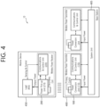
- FIG. 4 is a block diagram of a wireless power transmission system according to one embodiment.
- the wireless power transfer system (10) includes a mobile device (450), which wirelessly receives power, and a base station (400), which wirelessly transmits power.
- the base station (400) may include at least one of a wireless power transmitter (100) and a system unit (405).
- the wireless power transmitter (100) may transmit induction power or resonance power and may control the transmission.
- the wireless power transmitter (100) may include a power conversion unit (110) converting electric energy to a power signal by generating a magnetic field through a primary coil (or primary coils), and a communications & control unit (120) controlling the communication and power transfer between the wireless power receiver (200) in order to transfer power at an appropriate (or suitable) level.
- the system unit (405) may perform input power provisioning, controlling of multiple wireless power transmitters, and other operation controls of the base station (400), such as user interface control.
- the primary coil may generate an electromagnetic field by using an alternating current power (or voltage or current).
- the primary coil is supplied with an alternating current power (or voltage or current) of a specific frequency, which is being outputted from the power conversion unit (110). And, accordingly, the primary coil may generate a magnetic field of the specific frequency.
- the magnetic field may be generated in a non-radial shape or a radial shape.
- the wireless power receiver (200) receives the generated magnetic field and then generates an electric current. In other words, the primary coil wirelessly transmits power.
- a primary coil and a secondary coil may have randomly appropriate shapes.
- the primary coil and the secondary coil may correspond to copper wire being wound around a high-permeability formation, such as ferrite or a non-crystalline metal.
- the primary coil may also be referred to as a transmitting coil, a primary core, a primary winding, a primary loop antenna, and so on.
- the secondary coil may also be referred to as a receiving coil, a secondary core, a secondary winding, a secondary loop antenna, a pickup antenna, and so on.
- the primary coil and the secondary coil may each be provided in the form of a primary resonance antenna and a secondary resonance antenna.
- the resonance antenna may have a resonance structure including a coil and a capacitor.
- the resonance frequency of the resonance antenna may be determined by the inductance of the coil and a capacitance of the capacitor.
- the coil may be formed to have a loop shape.
- a core may be placed inside the loop.
- the core may include a physical core, such as a ferrite core, or an air core.
- the energy transmission (or transfer) between the primary resonance antenna and the second resonance antenna may be performed by a resonance phenomenon occurring in the magnetic field.
- the resonance phenomenon refers to a highly efficient energy transfer occurring between the two resonance antennas that are coupled with one another.
- the primary resonance antenna and the secondary resonance antenna resonate with one another.
- the magnetic field is focused toward the second resonance antenna at a higher efficiency as compared to a case where the magnetic field that is generated from the primary antenna is radiated to a free space.
- the magnetic induction method may be implemented similarly to the magnetic resonance method. However, in this case, the frequency of the magnetic field is not required to be a resonance frequency. Nevertheless, in the magnetic induction method, the loops configuring the primary coil and the secondary coil are required to match one another, and the distance between the loops should be very close-ranged.
- the wireless power transmitter (100) may further include a communication antenna.
- the communication antenna may transmit and/or receive a communication signal by using a communication carrier apart from the magnetic field communication.
- the communication antenna may transmit and/or receive communication signals corresponding to Wi-Fi, Bluetooth, Bluetooth LE, ZigBee, NFC, and so on.
- the communications & control unit (120) may transmit and/or receive information to and from the wireless power receiver (200).
- the communications & control unit (120) may include at least one of an IB communication module and an OB communication module.
- the IB communication module may transmit and/or receive information by using a magnetic wave, which uses a specific frequency as its center frequency.
- the communications & control unit (120) may perform in-band (IB) communication by transmitting communication information on the operating frequency of wireless power transfer through the primary coil or by receiving communication information on the operating frequency through the primary coil.
- the communications & control unit (120) may load information in the magnetic wave or may interpret the information that is carried by the magnetic wave by using a modulation scheme, such as binary phase shift keying (BPSK), Frequency Shift Keying (FSK) or amplitude shift keying (ASK), and so on, or a coding scheme, such as Manchester coding or non-return-to-zero level (NZR-L) coding, and so on.
- BPSK binary phase shift keying
- FSK Frequency Shift Keying
- ASK amplitude shift keying
- NZR-L non-return-to-zero level
- the OB communication module may also perform out-of-band communication through a communication antenna.
- the communications & control unit (120) may be provided to a near field communication module.
- the near field communication module may include communication modules, such as Wi-Fi, Bluetooth, Bluetooth LE, ZigBee, NFC, and so on.
- the communications & control unit (120) may control the overall operations of the wireless power transmitter (100).
- the communications & control unit (120) may perform calculation and processing of diverse information and may also control each configuration element of the wireless power transmitter (100).
- the communications & control unit (120) may be implemented in a computer or a similar device as hardware, software, or a combination of the same. When implemented in the form of hardware, the communications & control unit (120) may be provided as an electronic circuit performing control functions by processing electrical signals. And, when implemented in the form of software, the communications & control unit (120) may be provided as a program that operates the communications & control unit (120).
- the communications & control unit (120) may control the transmitted power.
- the operating point that is being controlled may correspond to a combination of a frequency (or phase), a duty cycle, a duty ratio, and a voltage amplitude.
- the communications & control unit (120) may control the transmitted power by adjusting any one of the frequency (or phase), the duty cycle, the duty ratio, and the voltage amplitude.
- the wireless power transmitter (100) may supply a consistent level of power
- the wireless power receiver (200) may control the level of received power by controlling the resonance frequency.
- the wireless power transmitter 100 may be classified, for example, in terms of power transmission amount.
- the wireless power transmitter 100 supporting a wireless power transmission amount of up to 5W i.e., the wireless power transmitter 100 supporting the BPP protocol
- the wireless power transmitter 100 supporting a wireless power transmission amount of up to 15W i.e., the wireless power transmitter 100 supporting the EPP protocol
- type MP-A MP-A
- type MP-B type MP-B
- Type A and Type MP A wireless power transmitters 100 may have one or more primary coils.
- Type A and Type MP A wireless power transmitters 100 activate a single primary coil at a time, so a single primary cell matching the activated primary coil can be used.
- Type B and Type MP B power transmitters may have a primary coil array. And Type B and Type MP B power transmitters can enable free positioning. To this end, Type B and Type MP B power transmitters can activate one or more primary coils in the array to realize primary cells at different locations on the interface surface.
- the mobile device (450) includes a wireless power receiver (200) receiving wireless power through a secondary coil, and a load (455) receiving and storing the power that is received by the wireless power receiver (200) and supplying the received power to the device.
- the wireless power receiver (200) may include a power pick-up unit (210) and a communications & control unit (220).
- the power pick-up unit (210) may receive wireless power through the secondary coil and may convert the received wireless power to electric energy.
- the power pick-up unit (210) rectifies the alternating current (AC) signal, which is received through the secondary coil, and converts the rectified signal to a direct current (DC) signal.
- the communications & control unit (220) may control the transmission and reception of the wireless power (transfer and reception of power).
- the secondary coil may receive wireless power that is being transmitted from the wireless power transmitter (100).
- the secondary coil may receive power by using the magnetic field that is generated in the primary coil.
- the specific frequency corresponds a resonance frequency
- magnetic resonance may occur between the primary coil and the secondary coil, thereby allowing power to be transferred with greater efficiency.
- the communications & control unit (220) may further include a communication antenna.
- the communication antenna may transmit and/or receive a communication signal by using a communication carrier apart from the magnetic field communication.
- the communication antenna may transmit and/or receive communication signals corresponding to Wi-Fi, Bluetooth, Bluetooth LE, ZigBee, NFC, and so on.
- the communications & control unit (220) may transmit and/or receive information to and from the wireless power transmitter (100).
- the communications & control unit (220) may include at least one of an IB communication module and an OB communication module.
- the IB communication module may transmit and/or receive information by using a magnetic wave, which uses a specific frequency as its center frequency.
- the communications & control unit (220) may perform IB communication by loading information in the magnetic wave and by transmitting the information through the secondary coil or by receiving a magnetic wave carrying information through the secondary coil.
- the communications & control unit (120) may load information in the magnetic wave or may interpret the information that is carried by the magnetic wave by using a modulation scheme, such as binary phase shift keying (BPSK), Frequency Shift Keying(FSK) or amplitude shift keying (ASK), and so on, or a coding scheme, such as Manchester coding or non-return-to-zero level (NZR-L) coding, and so on.
- BPSK binary phase shift keying
- FSK Frequency Shift Keying
- ASK amplitude shift keying
- NZR-L non-return-to-zero level
- the OB communication module may also perform out-of-band communication through a communication antenna.
- the communications & control unit (220) may be provided to a near field communication module.
- Examples of the near field communication module may include communication modules, such as Wi-Fi, Bluetooth, Bluetooth LE, ZigBee, NFC, and so on.
- the communications & control unit (220) may control the overall operations of the wireless power receiver (200).
- the communications & control unit (220) may perform calculation and processing of diverse information and may also control each configuration element of the wireless power receiver (200).
- the communications & control unit (220) may be implemented in a computer or a similar device as hardware, software, or a combination of the same. When implemented in the form of hardware, the communications & control unit (220) may be provided as an electronic circuit performing control functions by processing electrical signals. And, when implemented in the form of software, the communications & control unit (220) may be provided as a program that operates the communications & control unit (220).
- the communication/control circuit 120 and the communication/control circuit 220 are Bluetooth or Bluetooth LE as an OB communication module or a short-range communication module
- the communication/control circuit 120 and the communication/control circuit 220 may each be implemented and operated with a communication architecture as shown in FIG. 5 .
- FIG. 5 is a diagram illustrating an example of a Bluetooth communication architecture to which an embodiment according to the present disclosure may be applied.
- FIG. 5 shows an example of a protocol stack of Bluetooth basic rate (BR)/enhanced data rate (EDR) supporting GATT, and (b) shows an example of Bluetooth low energy (BLE) protocol stack.
- BR Bluetooth basic rate
- EDR enhanced data rate
- BLE Bluetooth low energy
- the Bluetooth BR/EDR protocol stack may include an upper control stack 460 and a lower host stack 470 based on a host controller interface (HCI) 18.
- HCI host controller interface
- the host stack (or host module) 470 refers to hardware for transmitting or receiving a Bluetooth packet to or from a wireless transmission/reception module which receives a Bluetooth signal of 2.4 GHz, and the controller stack 460 is connected to the Bluetooth module to control the Bluetooth module and perform an operation.
- the host stack 470 may include a BR/EDR PHY layer 12, a BR/EDR baseband layer 14, and a link manager layer 16.
- the BR/EDR PHY layer 12 is a layer that transmits and receives a 2.4 GHz radio signal, and in the case of using Gaussian frequency shift keying (GFSK) modulation, the BR/EDR PHY layer 12 may transmit data by hopping 79 RF channels.
- GFSK Gaussian frequency shift keying
- the BR/EDR baseband layer 14 serves to transmit a digital signal, selects a channel sequence for hopping 1400 times per second, and transmits a time slot with a length of 625 us for each channel.
- the link manager layer 16 controls an overall operation (link setup, control, security) of Bluetooth connection by utilizing a link manager protocol (LMP).
- LMP link manager protocol
- the link manager layer 16 may perform the following functions.
- the host controller interface layer 18 provides an interface between a host module and a controller module so that a host provides commands and data to the controller and the controller provides events and data to the host.
- the host stack (or host module, 470) includes a logical link control and adaptation protocol (L2CAP) 21, an attribute protocol 22, a generic attribute profile (GATT) 23, a generic access profile (GAP) 24, and a BR/EDR profile 25.
- L2CAP logical link control and adaptation protocol
- GATT generic attribute profile
- GAP generic access profile
- BR/EDR profile 25 BR/EDR profile
- the logical link control and adaptation protocol (L2CAP) 21 may provide one bidirectional channel for transmitting data to a specific protocol or profile.
- the L2CAP 21 may multiplex various protocols, profiles, etc., provided from upper Bluetooth.
- L2CAP of Bluetooth BR/EDR uses dynamic channels, supports protocol service multiplexer, retransmission, streaming mode, and provides segmentation and reassembly, per-channel flow control, and error control.
- the generic attribute profile (GATT) 23 may be operable as a protocol that describes how the attribute protocol 22 is used when services are configured.
- the generic attribute profile 23 may be operable to specify how ATT attributes are grouped together into services and may be operable to describe features associated with services.
- the generic attribute profile 23 and the attribute protocols (ATT) 22 may use features to describe device's state and services, how features are related to each other, and how they are used.
- the attribute protocol 22 and the BR/EDR profile 25 define a service (profile) using Bluetooth BR/EDR and an application protocol for exchanging these data, and the generic access profile (GAP) 24 defines device discovery, connectivity, and security level.
- profile a service
- GAP generic access profile
- the Bluetooth LE protocol stack includes a controller stack 480 operable to process a wireless device interface important in timing and a host stack 490 operable to process high level data.
- the controller stack 480 may be implemented using a communication module that may include a Bluetooth wireless device, for example, a processor module that may include a processing device such as a microprocessor.
- the host stack 490 may be implemented as a part of an OS running on a processor module or as an instantiation of a package on the OS.
- controller stack and the host stack may be run or executed on the same processing device in a processor module.
- the controller stack 480 includes a physical layer (PHY) 32, a link layer 34, and a host controller interface 36.
- PHY physical layer
- link layer 34 link layer
- host controller interface 36 host controller interface
- the physical layer (PHY, wireless transmission/reception module) 32 is a layer that transmits and receives a 2.4 GHz radio signal and uses Gaussian frequency shift keying (GFSK) modulation and a frequency hopping scheme including 40 RF channels.
- GFSK Gaussian frequency shift keying
- the link layer 34 which serves to transmit or receive Bluetooth packets, creates connections between devices after performing advertising and scanning functions using 3 advertising channels and provides a function of exchanging data packets of up to 257 bytes through 37 data channels.
- the host stack includes a generic access profile (GAP) 45, a logical link control and adaptation protocol (L2CAP, 41), a security manager (SM) 42, and an attribute protocol (ATT) 43, a generic attribute profile (GATT) 44, a generic access profile 45, and an LE profile 46.
- GAP generic access profile
- L2CAP logical link control and adaptation protocol
- SM security manager
- ATT attribute protocol
- GATT generic attribute profile
- the host stack 490 is not limited thereto and may include various protocols and profiles.
- the host stack multiplexes various protocols, profiles, etc., provided from upper Bluetooth using L2CAP.
- the logical link control and adaptation protocol (L2CAP) 41 may provide one bidirectional channel for transmitting data to a specific protocol or profile.
- the L2CAP 41 may be operable to multiplex data between higher layer protocols, segment and reassemble packages, and manage multicast data transmission.
- Bluetooth LE three fixed channels (one for signaling CH, one for security manager, and one for attribute protocol) are basically used. Also, a dynamic channel may be used as needed.
- a basic channel/enhanced data rate uses a dynamic channel and supports protocol service multiplexer, retransmission, streaming mode, and the like.
- the security manager (SM) 42 is a protocol for authenticating devices and providing key distribution.
- the attribute protocol (ATT) 43 defines a rule for accessing data of a counterpart device in a server-client structure.
- the ATT has the following 6 message types (request, response, command, notification, indication, confirmation).
- a value regarding a data length is transmitted to allow a client to clearly know the data length, and a characteristic value may be received from a server by using a universal unique identifier (UUID).
- UUID universal unique identifier
- the generic access profile (GAP) 45 a layer newly implemented for the Bluetooth LE technology, is used to select a role for communication between Bluetooth LED devices and to control how a multi-profile operation takes place.
- GAP 45 is mainly used for device discovery, connection generation, and security procedure part, defines a scheme for providing information to a user, and defines types of attributes as follows.
- the LE profile 46 is mainly applied to a Bluetooth LE device.
- the LE profile 46 may include, for example, Battery, Time, FindMe, Proximity, Time, Object Delivery Service, and the like, and details of the GATT-based profiles are as follows.
- the generic attribute profile (GATT) 44 may operate as a protocol describing how the attribute protocol (ATT) 43 is used when services are configured.
- the GATT 44 may operate to define how ATT attributes are grouped together with services and operate to describe features associated with services.
- the GATT 44 and the ATT 43 may use features in order to describe status and services of a device and describe how the features are related and used.
- the BLE procedure may be classified as a device filtering procedure, an advertising procedure, a scanning procedure, a discovering procedure, and a connecting procedure.
- the device filtering procedure is a method for reducing the number of devices performing a response with respect to a request, indication, notification, and the like, in the controller stack.
- the controller stack may perform control to reduce the number of transmitted requests to reduce power consumption.
- An advertising device or scanning device may perform the device filtering procedure to limit devices for receiving an advertising packet, a scan request or a connection request.
- the advertising device refers to a device transmitting an advertising event, that is, a device performing an advertisement and is also termed an advertiser.
- the scanning device refers to a device performing scanning, that is, a device transmitting a scan request.
- the scanning device in a case in which the scanning device receives some advertising packets from the advertising device, the scanning device should transmit a scan request to the advertising device.
- the scanning device may disregard the advertising packets transmitted from the advertising device.
- the device filtering procedure may be used. In a case in which device filtering is used in the connection request process, it is not necessary to transmit a response with respect to the connection request by disregarding the connection request.
- the advertising device performs an advertising procedure to perform undirected broadcast to devices within a region.
- the undirected broadcast is advertising toward all the devices, rather than broadcast toward a specific device, and all the devices may scan advertising to make an supplemental information request or a connection request.
- directed advertising may make an supplemental information request or a connection request by scanning advertising for only a device designated as a reception device.
- the advertising procedure is used to establish a Bluetooth connection with an initiating device nearby.
- the advertising procedure may be used to provide periodical broadcast of user data to scanning devices performing listening in an advertising channel.
- the advertising devices may receive scan requests from listening devices performing listening to obtain additional user data from advertising devices.
- the advertising devices transmit responses with respect to the scan requests to the devices which have transmitted the scan requests, through the same advertising physical channels as the advertising physical channels in which the scan requests have been received.
- Broadcast user data sent as part of advertising packets are dynamic data, while the scan response data is generally static data.
- the advertisement device may receive a connection request from an initiating device on an advertising (broadcast) physical channel. If the advertising device has used a connectable advertising event and the initiating device has not been filtered according to the device filtering procedure, the advertising device may stop advertising and enter a connected mode. The advertising device may start advertising after the connected mode.
- a device performing scanning that is, a scanning device performs a scanning procedure to listen to undirected broadcasting of user data from advertising devices using an advertising physical channel.
- the scanning device transmits a scan request to an advertising device through an advertising physical channel in order to request additional data from the advertising device.
- the advertising device transmits a scan response as a response with respect to the scan request, by including additional user data which has requested by the scanning device through an advertising physical channel.
- the scanning procedure may be used while being connected to other BLE device in the BLE piconet.
- the scanning device is in an initiator mode in which the scanning device may receive an advertising event and initiates a connection request.
- the scanning device may transmit a connection request to the advertising device through the advertising physical channel to start a Bluetooth connection with the advertising device.
- the scanning device When the scanning device transmits a connection request to the advertising device, the scanning device stops the initiator mode scanning for additional broadcast and enters the connected mode.
- Bluetooth devices Devices available for Bluetooth communication (hereinafter, referred to as “Bluetooth devices”) perform an advertising procedure and a scanning procedure in order to discover devices located nearby or in order to be discovered by other devices within a given area.
- the discovering procedure is performed asymmetrically.
- a Bluetooth device intending to discover other device nearby is termed a discovering device, and listens to discover devices advertising an advertising event that may be scanned.
- a Bluetooth device which may be discovered by other device and available to be used is termed a discoverable device and positively broadcasts an advertising event such that it may be scanned by other device through an advertising (broadcast) physical channel.
- Both the discovering device and the discoverable device may have already been connected with other Bluetooth devices in a piconet.
- a connecting procedure is asymmetrical, and requests that, while a specific Bluetooth device is performing an advertising procedure, another Bluetooth device should perform a scanning procedure.
- an advertising procedure may be aimed, and as a result, only one device may response to the advertising.
- a connecting request may be transmitted to the advertising device through an advertising (broadcast) physical channel to initiate connection.
- a link layer enters an advertising state according to an instruction from a host (stack). In a case in which the LL is in the advertising state, the LL transmits an advertising packet data unit (PDU) in advertising events.
- PDU packet data unit
- Each of the advertising events include at least one advertising PDU, and the advertising PDU is transmitted through an advertising channel index in use. After the advertising PDU is transmitted through an advertising channel index in use, the advertising event may be terminated, or in a case in which the advertising device may need to secure a space for performing other function, the advertising event may be terminated earlier.
- the LL enters the scanning state according to an instruction from the host (stack). In the scanning state, the LL listens to advertising channel indices.
- the scanning state includes two types: passive scanning and active scanning. Each of the scanning types is determined by the host.
- Time for performing scanning or an advertising channel index are not defined.
- a scan interval is defined as an interval between start points of two continuous scan windows.
- the LL When there is no collision in scheduling, the LL should listen in order to complete all the scan intervals of the scan window as instructed by the host. In each scan window, the LL should scan other advertising channel index. The LL uses every available advertising channel index.
- the LL In the passive scanning, the LL only receives packets and cannot transmit any packet.
- the LL performs listening in order to be relied on an advertising PDU type for requesting advertising PDUs and advertising device-related supplemental information from the advertising device.
- the LL enters the initiating state according to an instruction from the host (stack).
- the LL When the LL is in the initiating state, the LL performs listening on advertising channel indices.
- the LL listens to an advertising channel index during the scan window interval.
- the LL When the device performing a connection state, that is, when the initiating device transmits a CONNECT_REQ PDU to the advertising device or when the advertising device receives a CONNECT REQ PDU from the initiating device, the LL enters a connection state.
- connection is generated after the LL enters the connection state. However, it is not necessary to consider that the connection should be established at a point in time at which the LL enters the connection state. The only difference between a newly generated connection and an already established connection is a LL connection supervision timeout value.
- An LL serving as a master is termed a master, and an LL serving as a slave is termed a slave.
- the master adjusts a timing of a connecting event, and the connecting event refers to a point in time at which the master and the slave are synchronized.
- BLE devices use packets defined as follows.
- the LL has only one packet format used for both an advertising channel packet and a data channel packet.
- Each packet includes four fields of a preamble, an access address, a PDU, and a CRC.
- the PDU When one packet is transmitted in an advertising physical channel, the PDU may be an advertising channel PDU, and when one packet is transmitted in a data physical channel, the PDU may be a data channel PDU.
- An advertising channel PDU has a 16-bit header and payload having various sizes.
- a PDU type field of the advertising channel PDU included in the heater indicates PDU types defined in Table 1 below.
- PDU Type Packet Name 0000 ADV_IND 0001 ADV_DIRECT_IND 0010 ADV_NONCONN_IND 0011 SCAN_REQ 0100 SCAN_RSP 0101 CONNECT_REQ 0110 ADV_SCAN_IND 0111-1111 Reserved
- advertising channel PDU types are termed advertising PDUs and used in a specific event.
- the following advertising channel DPU types are termed scanning PDUs and are used in a state described hereinafter.
- SCAN_REQ Transmitted by the LL in a scanning state and received by the LL in an advertising state.
- SCAN_RSP Transmitted by the LL in the advertising state and received by the LL in the scanning state.
- the following advertising channel PDU type is termed an initiating PDU.
- CONNECT REQ Transmitted by the LL in the initiating state and received by the LL in the advertising state.
- the data channel PDU may include a message integrity check (MIC) field having a 16-bit header and payload having various sizes.
- MIC message integrity check
- the load (455) may correspond to a battery.
- the battery may store energy by using the power that is being outputted from the power pick-up unit (210). Meanwhile, the battery is not mandatorily required to be included in the mobile device (450).
- the battery may be provided as a detachable external feature.
- the wireless power receiver may include an operating means that may execute diverse functions of the electronic device instead of the battery.
- the mobile device (450) is illustrated to be included in the wireless power receiver (200) and the base station (400) is illustrated to be included in the wireless power transmitter (100), in a broader meaning, the wireless power receiver (200) may be identified (or regarded) as the mobile device (450), and the wireless power transmitter (100) may be identified (or regarded) as the base station (400).
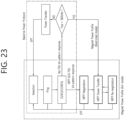
- the wireless power transmitter 100 including the communication/control circuit 120 and the wireless power receiver 200 including the communication/control circuit 220 may be represented by a simplified block diagram as shown in FIG. 6 .
- FIG. 6 is a block diagram illustrating a wireless power transfer system using BLE communication according to an example.
- the wireless power transmitter 100 includes a power conversion circuit 110 and a communication/control circuit 120.
- the communication/control circuit 120 includes an in-band communication module 121 and a BLE communication module 122.
- the wireless power receiver 200 includes a power pickup circuit 210 and a communication/control circuit 220.
- the communication/control circuit 220 includes an in-band communication module 221 and a BLE communication module 222.
- the BLE communication modules 122 and 222 perform the architecture and operation according to FIG. 5 .
- the BLE communication modules 122 and 222 may be used to establish a connection between the wireless power transmitter 100 and the wireless power receiver 200 and exchange control information and packets necessary for wireless power transfer.
- the communication/control circuit 120 may be configured to operate a profile for wireless charging.
- the profile for wireless charging may be GATT using BLE transmission.
- FIG. 7 is a block diagram illustrating a wireless power transfer system using BLE communication according to another example.
- the communication/control circuits 120 and 220 respectively include only in-band communication modules 121 and 221, and the BLE communication modules 122 and 222 may be provided to be separated from the communication/control circuits 120 and 220.
- the coil or coil unit includes a coil and at least one device being approximate to the coil, and the coil or coil unit may also be referred to as a coil assembly, a coil cell, or a cell.
- the wireless power transmitter 100 and the wireless power receiver 200 begin communication for the purpose of configuring and controlling power transmission.
- the power signal can provide a carrier for all communications, and the protocol for communication can be composed of several steps.
- the communication protocol will be described.
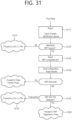
- FIG. 8 is a state transition diagram for explaining the wireless power transfer procedure.
- WPC can define two communication protocols.
- the power transfer operation between the wireless power transmitter 100 and the wireless power receiver 200 can be largely divided into a ping phase (810), a configuration phase (820), a negotiation phase (830), and a power transfer phase.
- the wireless power transmitter 100 may attempt to establish communication with the wireless power receiver 200. Before attempting to establish communication, measurements may be performed to determine whether there are objects such as bank cards, coins or other metals that may be damaged or heated during power transfer. Here, these measurements can be performed without waking up the wireless power receiver 200.
- the wireless power transmitter 100 may postpone a conclusion about whether the detected metal is a foreign object or a friendly metal to the negotiation phase 830.
- the wireless power receiver 200 may send basic identification and configuration data to the wireless power receiver 200. And, both the wireless power transmitter 100 and the wireless power receiver 200 can use this information to create a baseline power transfer contract.
- the wireless power transmitter 100 and the wireless power receiver 200 may determine whether to continue the baseline protocol or the extended protocol in the configuration phase 820.
- the wireless power receiver 200 can use functions such as enhanced FOD, data transport stream, and authentication only when implementing the extended protocol.
- the wireless power transmitter 100 and the wireless power receiver 200 may establish an extended power transfer contract that includes additional settings and restrictions. Additionally, the wireless power receiver 200 may provide design information to the wireless power transmitter 100. Later, the design information can be used to complete the FOD before transitioning to the power transfer phase 840.
- the negotiation phase 830 may correspond to a step that does not exist in the baseline protocol.
- the power transfer phase 840 may be a step in which power is transferred to the load of the wireless power receiver 200.
- the wireless power transmitter 100 and the wireless power receiver 200 may perform system calibration when this step begins. This stage may occasionally be interrupted to renegotiate elements of the power transfer contract. However, power transfer may continue even during this renegotiation.
- the wireless power transmitter 100 does not yet know whether the wireless power receiver 200 is within the operating volume. In addition, the wireless power transmitter 100 cannot recognize the wireless power receiver 200. For that reason, this system is usually disabled due to lack of power signal.
- the wireless power transmitter 100 may go through the following steps.
- FIG. 9 schematically shows an example of the protocol of the ping phase 810.
- the wireless power transmitter 100 can perform analog ping (S910). That is, the wireless power transmitter 100 can confirm whether an object exists in the operating volume by transmitting an analog ping. For example, a wireless power transmitter can detect whether an object exists in the operating space based on a change in current in the transmission coil or primary coil.
- the wireless power transmitter 100 may apply NFC tag protection (S920).
- NFC tag protection can be performed through the following procedures.
- the wireless power transmitter 100 may perform foreign object detection (S930). That is, the wireless power transmitter 100 can collect information helpful in determining whether there is a foreign object other than the wireless power receiver 200. For this purpose, the wireless power transmitter 100 can use various methods such as a pre-power FOD method.
- the radio power receiver may not operate.
- the wireless power transmitter 100 may start a digital ping (S940).
- the digital ping may request a response such as a signal strength (SIG) data packet or an end power transfer (EPT) data packet from the wireless power receiver 200.
- SIG signal strength
- EPT end power transfer
- the wireless power transmitter 100 may receive the SIG or EPT from the wireless power receiver 200 (S950).
- the SIG data packet may provide a measure of coupling, and the SIG data packet may include information about signal strength values.
- the EPT data packet may provide a request to stop power transmission and a reason for the request.
- the wireless power transmitter 100 may repeat the above steps while remaining in the ping phase 810.
- the configuration phase 820 is part of the following protocol.
- the wireless power transmitter 100 and the wireless power receiver 200 may continue to operate using the digital ping parameter. This may mean that the power and current levels of both the wireless power transmitter 100 and the wireless power receiver 200 change only when the user moves the wireless power receiver 200 from position within the operating volume.
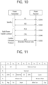
- FIG. 10 schematically shows an example of the protocol of the configuration phase 820.
- the wireless power transmitter 100 may receive an identification (ID) from the wireless power receiver 200 (S1010).
- the wireless power transmitter 100 may also receive an extended identification (XID) from the wireless power receiver 200 (S1020). That is, the wireless power receiver 200 may identify itself using an ID data packet and, optionally, an XID data packet.
- ID identification
- XID extended identification
- the wireless power transmitter 100 may selectively receive a power control hold-off (PCH) data packet from the wireless power receiver 200 (S1030), the wireless power transmitter 100 may receive a CFG data packet from the wireless power receiver 200 (S1040). That is, the wireless power receiver 200 can provide data for use in a power transfer contract using PCH and/or CFG data packets.
- PCH power control hold-off
- the wireless power transmitter 100 can check the extended protocol if possible (S1050).
- a CFG data packet can provide all parameters governing power transfer in the baseline protocol.
- CFG data packets can provide all FSK communication parameters used in the extended protocol.
- CFG data packets may provide additional functions of the wireless power receiver 200.
- FIG. 11 is a diagram illustrating a message field of a configuration packet (CFG) of a wireless power reception device according to an embodiment.
- CFG configuration packet
- the configuration packet (CFG) may have a header value of 0x51, and the message field of the configuration packet (CFG) may include a 1-bit authentication (AI) flag and a 1-bit outband (OB) flag.
- AI 1-bit authentication
- OB 1-bit outband
- the authentication flag (AI) indicates whether the wireless power receiving device supports the authentication function. For example, if the value of the authentication flag (AI) is '1', it indicates that the wireless power receiving device supports the authentication function or can operate as an authentication initiator, if the value of the authentication flag (AI) is '0', it may indicate that the wireless power receiving device does not support the authentication function or cannot operate as an authentication initiator.
- the out-of-band (OB) flag indicates whether the wireless power receiving device supports out-of-band communication. For example, if the value of the out-of-band (OB) flag is '1', the wireless power receiver indicates out-of-band communication, if the value of the outband (OB) flag is '0', it may indicate that the wireless power receiving device does not support outband communication.
- Provision of the ID and/or XID described above is for identification purposes. Additionally, the provision of PCH and/or CFG is for the construction of a power transfer contract.
- the negotiation phase 830 is part of an extended protocol that allows the wireless power transmitter 100 and the wireless power receiver 200 to change the power transfer contract. There are two types of this stage.
- the power transfer contract related to the reception/transmission of wireless power between a wireless power receiving device and a wireless power transmitting device is expanded or changed, or a renewal of the power transfer contract is made that adjusts at least some of the elements of the power transfer contract, or information may be exchanged to establish out-of-band communication.
- FIG. 12 is a flowchart schematically illustrating a protocol of a negotiation stage or a renegotiation stage according to an embodiment.
- the wireless power transmitter 100 may receive a FOD status data packet (e.g. FOD) from the wireless power receiver 200 (S1210).
- FOD status data packet e.g. FOD
- the wireless power receiver 200 can use the FOD status data packet to inform the wireless power transmitter 100 of the effect its presence has on selected properties of the reference wireless power transmitter 100.
- the wireless power transmitter 100 can configure the FOD function using this information.
- the wireless power transmitter 100 may transmit an ACK/NAK for the FOD status data packet to the wireless power receiver 200 (S1215).
- the wireless power receiver 200 may receive an identification data packet (ID), a capabilities data packet (CAP), and an extended CAP (XCAP) of the wireless power transmitter 100 using a general request data packet (GRQ).
- ID identification data packet
- CAP capabilities data packet
- XCAP extended CAP
- the general request packet may have a header value of 0x07 and may include a 1-byte message field.
- the message field of the general request packet (GRQ) may include a header value of a data packet that the wireless power receiver 200 requests from the wireless power transmitter 100 using the GRQ packet.
- the wireless power receiver 200 may transmit a GRQ packet (GRQ/id) requesting an ID packet of the wireless power transmitter 100 to the wireless power transmitter 100 (S1220).
- GRQ/id GRQ/id
- the wireless power transmitter 100 that has received the GRQ/id may transmit an ID packet to the wireless power receiver 200 (S 1225).
- the ID packet of the wireless power transmitter 100 includes information about the 'Manufacturer Code'.
- the ID packet containing information about the 'Manufacturer Code' allows the manufacturer of the wireless power transmitter 100 to be identified.
- the wireless power receiver 200 may transmit a GRQ packet (GRQ/cap) requesting a capability packet (CAP) of the wireless power transmitter 100 to the wireless power transmitter 100 (S1230).
- GRQ/cap GRQ packet
- the message field of GRQ/cap may include the header value (0x31) of the capability packet (CAP).
- the wireless power transmitter 100 that has received the GRQ/cap may transmit a capability packet (CAP) to the wireless power receiver 200 (S1235).
- CAP capability packet
- the wireless power receiver 200 may transmit a GRQ packet (GRQ/xcap) requesting a capability packet (CAP) of the wireless power transmitter 100 to the wireless power transmitter 100 (S1240).
- GRQ/xcap may include the header value (0x32) of the performance packet (XCAP).
- the wireless power transmitter 100 that has received GRQ/xcap may transmit a capability packet (XCAP) to the wireless power receiver 200 (S1245).
- XCAP capability packet
- FIG. 13 is a diagram illustrating a message field of a capability packet (CAP) of a wireless power transmission device according to an embodiment.
- CAP capability packet
- a capability packet may have a header value of 0x31 and, referring to FIG. 13 , may include a 3-byte message field.
- the message field of the capability packet may include a 1-bit authentication (AR) flag and a 1-bit outband (OB) flag.
- the authentication flag (AR) indicates whether the wireless power transmitter 100 supports the authentication function. For example, if the value of the authentication flag (AR) is '1', it indicates that the wireless power transmitter 100 supports an authentication function or can operate as an authentication responder, if the value of the authentication flag (AR) is '0', it may indicate that the wireless power transmitter 100 does not support the authentication function or cannot operate as an authentication responder.
- the outband (OB) flag indicates whether the wireless power transmitter 100 supports outband communication. For example, if the value of the outband (OB) flag is '1', the wireless power transmitter 100 instructs outband communication, if the value of the out-of-band (OB) flag is '0', this may indicate that the wireless power transmitter 100 does not support out-of-band communication.
- the wireless power receiver 200 can receive the capability packet (CAP) of the wireless power transmitter 100 and check whether the wireless power transmitter 100 supports the authentication function and whether out-band communication is supported.
- CAP capability packet
- the wireless power receiver 200 can update the elements of the power transfer contract (Power Transfer Contract) related to the power to be provided in the power transfer phase using at least one specific request packet (SRQ, Specific Request data packet) in the negotiation phase or re-negotiation phase (S1250), ACK/NAK for this can be received (S1255).
- Power Transfer Contract the elements of the power transfer contract related to the power to be provided in the power transfer phase using at least one specific request packet (SRQ, Specific Request data packet) in the negotiation phase or re-negotiation phase (S1250), ACK/NAK for this can be received (S1255).
- the wireless power receiver 200 transmits SRQ/en to the wireless power transmitter 100 (S 1260), it can receive ACK from the wireless power transmitter 100 (S 1265).
- the power transfer phase 840 is a part of the protocol in which actual power is transferred to the load of the wireless power receiver 200.
- power transfer may proceed according to the conditions of the power transfer contract created in the negotiation phase 830.
- the wireless power receiver 200 can control the power level by transmitting control error (CE) data that measures the deviation between the target and the actual operating point of the wireless power receiver 200 to the wireless power transmitter 100.
- CE control error
- the wireless power transmitter 100 and wireless power receiver 200 aim to make the control error data zero, at which point the system will operate at the target power level.
- the wireless power transmitter 100 and the wireless power receiver 200 may exchange information to facilitate FOD.
- the wireless power receiver 200 regularly reports the amount of power it receives (received power level) to the wireless power transmitter 100, the wireless power transmitter 100 may inform the wireless power receiver 200 whether a foreign object has been detected. Methods that can be used for FOD in the power transfer phase may correspond to, for example, power loss calculations.
- the wireless power transmitter 100 compares the received power level reported by the wireless power receiver 200 with the amount of transmitted power (transmitted power level) and it can send a signal (whether a foreign object has been monitored) to the wireless power receiver 200 when the difference exceeds a threshold.
- the wireless power transmitter 100 or the wireless power receiver 200 may request renegotiation of the power transfer contract during the power transfer phase.
- Examples of changed circumstances in which renegotiation of a power transfer contract may occur include:
- the wireless power transmitter 100 and the wireless power receiver 200 may start a data transmission stream and exchange application level data throughout the power transfer phase 840.
- each side can verify the other's credentials in a tamper-proof manner.
- the wireless power receiver 200 may want to check the credentials of the wireless power transmitter 100 to ensure that the wireless power transmitter 100 can be trusted to operate safely at high power levels. Having the appropriate credentials can mean you have passed compliance testing.
- the present specification may provide a method of starting power transfer at a low power level and controlling power to a higher level only after successfully completing the authentication protocol.
- the operation between the wireless power transmitter 100 and the wireless power receiver 200 in the power transfer phase 840 has been briefly described.
- the protocol in the power transfer phase 840 will be described separately as a baseline protocol and an extended protocol.
- FIG. 14 schematically shows a flow chart of the data flow for the power transfer phase 840 in the baseline protocol.
- the wireless power receiver 200 may transmit CE to the wireless power transmitter 100 (S1410).
- the wireless power receiver 200 can generally transmit CE data packets several times per second.
- the wireless power receiver 200 may generally transmit a received power (RP) data packet (RP8 in the baseline protocol) to the wireless power transmitter 100 once every 1.5 seconds (S1420).
- RP received power
- the wireless power receiver 200 may transmit a charge status (CHS) data packet to the wireless power transmitter 100 (S 1430).
- CHS charge status
- FIG. 15 schematically shows a flow chart of the data flow for the power transfer phase 840 in the extended protocol.
- the wireless power receiver 200 may transmit CE to the wireless power transmitter 100 (S1510).
- the wireless power receiver 200 can generally transmit CE data packets several times per second.
- the wireless power receiver 200 may generally transmit a received power (RP) data packet (RP in the extended protocol) to the wireless power transmitter 100 once every 1.5 seconds (S1515).
- RP received power
- control error packets (CE) and received power packets (RP) are data packets that must be repeatedly transmitted/received according to the required timing constraints to control wireless power.
- the wireless power transmitter 100 can control the level of wireless power transmitted based on the control error packet (CE) and received power packet (RP) received from the wireless power receiver 200.
- CE control error packet
- RP received power packet
- the wireless power transmitter 100 may respond to the received power packet (RP) with a bit pattern such as ACK, NAK, or ATN (S1520).
- the fact that the wireless power transmitter 100 responds with ACK to a received power packet (RP/0) with a mode value of 0 means that power transmission can continue at the current level.
- the wireless power transmitter 100 responds with NAK to a received power packet (RP/0) with a mode value of 0, this means that the wireless power receiver 200 must reduce power consumption.
- the received power packet (RP/1) with a mode value of 1 described above may mean the first calibration data point
- a received power packet (RP/2) with a mode value of 2 may mean an additional calibration data point.
- the wireless power receiver may transmit a received power packet (RP/2) with a mode value of 2 to the wireless power transmitter multiple times to transmit a plurality of additional power calibration values, the wireless power transmitter can proceed with a calibration procedure based on the received RP/1 and multiple RP/2.
- the wireless power transmitter 100 When the wireless power transmitter 100 responds with ATN to the received power packet (RP), it means that the wireless power transmitter 100 requests permission for communication. That is, the wireless power transmitter 100 may transmit an attention (ATN) response pattern to request permission to transmit a data packet in response to an RP data packet. In other words, the wireless power transmitter 100 may transmit an ATN to the wireless power receiver 200 in response to the RP data packet and request the wireless power receiver 200 for permission to transmit the data packet.
- ATN attention
- the wireless power receiver 200 may transmit a charge status (CHS) data packet to the wireless power transmitter 100 (S 1525).
- CHS charge status
- the wireless power transmitter 100 and the wireless power receiver 200 can exchange data stream response (DSR) data packets, CAP data packets, and NEGO data packets to initiate renegotiation of elements of the power transfer contract (typically guaranteed load power).
- DSR data stream response
- the wireless power receiver 200 transmits a DSR data packet to the wireless power transmitter 100 (S1530), the wireless power transmitter 100 may transmit a CAP to the wireless power receiver 200 (S1535).
- the wireless power receiver 200 transmits a NEGO data packet to the wireless power transmitter 100 (S1540), the wireless power transmitter 100 may transmit an ACK to the wireless power receiver 200 in response to the NEGO data packet (S1545).
- the wireless power transmitter 100 and the wireless power receiver 200 may use auxiliary data transport (ADC), auxiliary data transport (ADT), and DSR data packets to exchange application level data.
- ADC auxiliary data transport
- ADT auxiliary data transport
- DSR DSR data packets
- the wireless power receiver 200 may transmit ADC/ADT to the wireless power transmitter 100 (S1550), the wireless power transmitter 100 may transmit an ACK/NAK to the wireless power receiver 200 in response (S1555).
- the wireless power receiver 200 can transmit DSR to the wireless power transmitter 100 (S1560), the wireless power transmitter may transmit ADC/ADT to the wireless power receiver (S1565).
- the data transport stream serves to transfer application-level data from the data stream initiator to the data stream responder.
- application level data can be broadly divided into i) authentication applications, and ii) proprietary (general purpose) applications.
- messages/information related to the authentication application can be organized as follows.
- the message used in the authentication procedure is called an authentication message.
- Authentication messages are used to convey information related to authentication. There are two types of authentication messages. One is an authentication request, and the other is an authentication response. An authentication request is sent by an authentication initiator, and an authentication response is sent by an authentication responder.
- the wireless power transmitting device and receiving device can be an authentication initiator or an authentication responder. For example, if the wireless power transmitting device is the authentication initiator, the wireless power receiving device becomes the authentication responder, and if the wireless power receiving device is the authentication initiator, the wireless power transmitting device becomes the authentication responder.
- Authentication request messages include GET_DIGESTS, GET_CERTIFICATE, and CHALLENGE.
- the authentication response message includes DIGESTS, CERTIFICATE, CHALLENGE AUTH, and ERROR.
- the authentication message may be called an authentication packet, authentication data, or authentication control information. Additionally, messages such as GET_DIGEST and DIGESTS may also be called GET DIGEST packets, DIGEST packets, etc.
- Application-level data transmitted through a data transport stream may consist of a data packet sequence with the following structure.
- FIG. 16 illustrates an application-level data stream between the wireless power transmitter 100 and the wireless power receiver 200 according to an example.
- the data stream may include auxiliary data control (ADC) data packets and/or auxiliary data transport (ADT) data packets.
- ADC auxiliary data control
- ADT auxiliary data transport
- ADC data packets are used to open a data stream.
- ADC data packets can indicate the type of message included in the stream and the number of data bytes.
- ADT data packets are sequences of data containing the actual message.
- ADC/end data packets are used to signal the end of a stream. For example, the maximum number of data bytes in a data transport stream may be limited to 2047.
- ACK or NAC is used to notify whether ADC data packets and ADT data packets are normally received.
- control information necessary for wireless charging such as a control error packet (CE) or DSR, may be transmitted.
- authentication-related information or other application-level information can be transmitted and received between a wireless power transmitter and a receiver.
- FIG. 17 shows a power control method according to one embodiment.
- the wireless power transmitter 100 and the wireless power receiver 200 can control the amount of power transferred by performing communication along with power transmission and reception.
- the wireless power transmitter and wireless power receiver operate at a specific control point.
- the control point represents the combination of voltage and current provided from the output of the wireless power receiver when power transfer is performed.
- the wireless power receiver selects a desired control point, a desired output current/voltage, a temperature at a specific location of the mobile device, and so on, and additionally determines an actual control point at which the receiver is currently operating.
- the wireless power receiver calculates a control error value by using the desired control point and the actual control point, and, then, the wireless power receiver may transmit the calculated control error value to the wireless power transmitter as a control error packet.
- the wireless power transmitter may configure/control a new operating point - amplitude, frequency, and duty cycle - by using the received control error packet, so as to control the power transfer. Therefore, the control error packet may be transmitted/received at a constant time interval during the power transfer phase, and, according to the exemplary embodiment, in case the wireless power receiver attempts to reduce the electric current of the wireless power transmitter, the wireless power receiver may transmit the control error packet by setting the control error value to a negative number. And, in case the wireless power receiver intends to increase the electric current of the wireless power transmitter, the wireless power receiver transmit the control error packet by setting the control error value to a positive number. During the induction mode, by transmitting the control error packet to the wireless power transmitter as described above, the wireless power receiver may control the power transfer.
- the device may be operated by using a method that is different from the induction mode.
- one wireless power transmitter should be capable of serving a plurality of wireless power receivers at the same time.
- a method of controlling the amount of power that is being received by having the wireless power transmitter commonly transfer (or transmit) the basic power and by having the wireless power receiver control its own resonance frequency. Nevertheless, even during the operation of the resonance mode, the method described above in FIG. 17 will not be completely excluded. And, additional control of the transmitted power may be performed by using the method of FIG. 17 .
- Wireless charging methods include a magnetic induction method using a magnetic induction phenomenon between a primary coil and a secondary coil, and a magnetic resonance method in which magnetic resonance is achieved using a frequency in a band of several tens of kHz to several MHz to transmit power.
- the wireless charging standard for the magnetic resonance method is led by a conference called A4WP
- the magnetic induction method is led by the WPC (Wireless Power Consortium).
- the WPC is designed to exchange various status information and commands related to the wireless charging system in-band.
- BPP baseline power profile
- EPP extended power profile
- BPP Baseline power profile
- BPP relates to a power transfer profile between a wireless power transmitter and receiver that supports power transfer of up to 5W. And, in BPP, unidirectional communication from a wireless power receiver to a wireless power transmitter is supported. The communication method at this time may correspond to ASK (amplitude shift keying). In BPP, there may be protocol phases of ping, configuration, and power transfer.
- ASK amplitude shift keying
- EPP relates to a power transfer profile between a wireless power transmitter and receiver that supports power transfer of up to 15W. And, in EPP, bidirectional communication between a wireless power receiver and a wireless power transmitter is supported.
- the communication method from the wireless power receiver to the wireless power transmitter may correspond to ASK (amplitude shift keying), the communication method from the wireless power transmitter to the wireless power receiver may correspond to frequency shift keying (FSK).
- ASK amplitude shift keying
- FSK frequency shift keying
- EPP may correspond to a higher profile of BPP.
- the EPP wireless power transmitter can operate as a BPP wireless power transmitter.
- the EPP wireless power receiver can operate as a BPP wireless power receiver.
- EPP can maintain compatibility with BPP.
- the EPP wireless power receiver can indicate that it is an EPP wireless power receiver by setting the 'neg' bit in the configuration packet (i.e. CFG) to 1.
- configuration packets are as described above.
- the EPP wireless power transmitter When the EPP wireless power transmitter receives a configuration packet with the 'neg' bit set to 1 from the wireless power receiver, the EPP wireless power transmitter may respond to the wireless power receiver with an ACK FSK bit pattern.
- the BPP wireless power transmitter does not support the FSK communication method, so the BPP wireless power transmitter cannot transmit FSK bit patterns. Accordingly, by not receiving the above ACK response, the EPP wireless power receiver, which sets the 'neg' bit to 1 and transmits a configuration packet to the BPP wireless power transmitter, can identify the other wireless power transmitter as a BPP wireless power transmitter.
- MPP magnetic power profile
- MPP relates to a power transfer profile between a wireless power transmitter and receiver that supports power transfer of up to 15W. And, in MPP, bidirectional communication between a wireless power receiver and a wireless power transmitter is supported.
- the communication method from the wireless power receiver to the wireless power transmitter may correspond to ASK (amplitude shift keying), the communication method from the wireless power transmitter to the wireless power receiver may correspond to frequency shift keying (FSK).
- ASK amplitude shift keying
- FSK frequency shift keying
- MPP there may be protocol phases of ping, configuration, MPP negotiation, and MPP power transfer.
- MPP may correspond to a higher profile of BPP.
- the MPP wireless power transmitter can operate as a BPP wireless power transmitter.
- the MPP wireless power receiver can operate as a BPP wireless power receiver.
- MPP can maintain compatibility with BPP.
- the MPP wireless power receiver may use a specific MPP indicator within the extended ID packet.
- the wireless power receiver In order for the MPP wireless power receiver to indicate whether MPP is supported through XID, the wireless power receiver must inform the wireless power transmitter that the XID is transmitted through an ID packet.
- the ID packet transmitted by the MPP wireless power receiver may be as follows.
- FIG. 18 schematically shows the structure of an MPP ID packet.
- the value of the major version field from b4 to b7 of B0 may be set to 1.
- the value of the minor version field from b0 to b3 of B0 may be a value to be determined later.
- the values of the manufacturer codes of B1 and B2 may be assigned as PRMC codes.
- the value of the 'ext' field of b7 of B3 may be set to 1 to indicate that an XID packet is additionally transmitted.
- the values of the random identifier fields of b0 to b6 of B3 and b3 to b7 of B4 and B5 may be set according to a random device identification policy.
- FIG. 19 schematically shows an example of an XID packet in MPP.
- an XID packet in MPP may include an 'XID Selector' field, a 'Restricted' field, and a 'Freq Mask' field.
- whether MPP is supported can be determined depending on whether the value of 'XID selector' is 0xFE. That is, if the value of B_0 of the XID is 0xFE, the XID at this time may correspond to information indicating that the wireless power receiver supports MPP.
- the 'Restricted' field may correspond to information indicating whether the wireless power receiver operates in MPP restricted mode or MPP full mode. If the wireless power receiver selects to operate in MPP limited mode, the above field can be set to 1. Meanwhile, in other cases (e.g., when the wireless power receiver selects not to operate in MPP limited mode), the above field may be set to 0.
- the 'Preferred Frequency' field may mean the MPP preferred frequency.
- this field can be set to 128 kHz. Otherwise, the wireless power receiver can set this field to 360 kHz.
- the 'Freq Mask' field corresponds to a field for determining whether the operating frequency of 360 kHz is supported. That is, if the 'Freq Mask' field is set to 0, 360kHz is supported.
- the wireless power transmitter determines whether the 'Ext' bit of the ID received from the wireless power receiver is set to 1 and determines whether B_0 of the XID is set to 0xFE, the wireless power transmitter can determine whether the wireless power receiver supports MPP.
- the MPP wireless power transmitter can use the information contained in the ID and XID packets to perform a digital ping and identify the receiver.
- the wireless power transmitter may determine that the wireless power receiver supports MPP if all of the following conditions are met.
- the wireless power transmitter can proceed with subsequent procedures according to the Qi v1.3 specification.
- the wireless power transmitter performs the following.
- the MPP wireless power transmitter when the MPP wireless power transmitter receives a configuration packet with the 'neg' bit set to 1 from the wireless power receiver, the MPP wireless power transmitter (in MPP full mode) may respond to this to the wireless power receiver with an MPP ACK FSK bit pattern.
- the wireless power transmitter in MPP restricted mode does not support the FSK communication method, so the wireless power transmitter in MPP restricted mode cannot transmit FSK bit patterns.
- the wireless power transmitter in MPP restricted mode uses a 360 kHz operation signal to transmit power, accordingly, the MPP wireless power receiver setting the 'neg' bit to 1 and transmitting the configuration packet to the wireless power transmitter operating in MPP restricted mode allows the other wireless power transmitter to be identified as an MPP restricted mode wireless power transmitter through the operating frequency.
- MPP restricted mode MPP Restricted mode
- MPP Full mode in other words, MPP full profile
- the 'restricted' field in the XID is set to 1, but in MPP full mode, the 'restricted' field in the XID is set to 0.
- FSK communication is not supported in MPP restricted mode, but FSK communication can be supported in MPP full mode.
- MPP ACK for CFG cannot be transmitted, accordingly, MPP negotiation is not supported in MPP restricted mode.
- MPP full mode FSK communication is supported, so MPP ACK for CFG can be transmitted, accordingly, MPP negotiation can be supported in MPP full mode.
- MPP restricted mode can be mixed with the MPP baseline profile
- MPP full mode can be mixed with the MPP full profile
- MPP restricted mode As explained previously, FSK communication is not supported in MPP restricted mode. That is, in MPP restricted mode, there may be no data packets transmitted from the wireless power transmitter to the wireless power receiver. Against this background, the protocol in MPP restricted mode will be explained through drawings.
- FIG. 20 schematically shows the protocol in MPP restricted mode.
- the wireless power receiver may transmit a SIG to the wireless power transmitter on a first operating frequency (e.g., 128 kHz).
- a first operating frequency e.g. 128 kHz.
- the first operating frequency may correspond to an operating frequency at which BPP and/or EPP can be performed.
- the first operating frequency at this time corresponds to the frequency at which the wireless power transmitter operates.
- the wireless power receiver may transmit an ID packet to the wireless power transmitter on a first operating frequency.
- the 'ext' bit of the ID may be set to 1 to indicate that the XID is additionally transmitted.
- the wireless power receiver may transmit an XID packet to the wireless power transmitter on a first operating frequency.
- the value of B0 in the XID may be 0xFE, and if the value of B0 in the XID is set to 0xFE, this may correspond to information indicating that the wireless power receiver supports MPP.
- the 'Restricted' field in the XID at this time may be set to 1 to indicate that the wireless power receiver operates in MPP restricted mode.
- the wireless power transmitter may remove the power signal and restart the ping phase at a new operating frequency.
- the wireless power receiver begins transmitting the SIG again.
- the operating frequency at this time may be a second operating frequency (e.g., 360 kHz).
- the wireless power receiver transmits ID, XID, and CFG packets to the wireless power transmitter at the second operating frequency, respectively.
- the wireless power receiver can receive wireless power based on the MPP baseline from the wireless power transmitter by transmitting a CEP to the wireless power transmitter.
- FSK communication can be supported in MPP full mode. That is, in MPP full mode, there may be data packets transmitted from the wireless power transmitter to the wireless power receiver. In other words, MPP negotiation, etc. may be conducted between a wireless power transmitter and a wireless power receiver. Against this background, the protocol in MPP full mode will be explained through the drawings.
- FIGS. 21 and 22 schematically show the protocol in MPP full mode.
- the wireless power receiver may transmit a SIG to the wireless power transmitter on a first operating frequency (e.g., 128 kHz).
- a first operating frequency e.g. 128 kHz.
- the first operating frequency may correspond to an operating frequency at which BPP and/or EPP can be performed.
- the first operating frequency at this time corresponds to the frequency at which the wireless power transmitter operates.
- the wireless power receiver may transmit an ID packet to the wireless power transmitter on a first operating frequency.
- the 'ext' bit of the ID may be set to 1 to indicate that the XID is additionally transmitted.
- the wireless power receiver may transmit an XID packet to the wireless power transmitter on a first operating frequency.
- the value of B0 in the XID may be 0xFE, and if the value of B0 in the XID is set to 0xFE, this may correspond to information indicating that the wireless power receiver supports MPP.
- the 'Restricted' field in the XID at this time may be set to 0 to indicate that the wireless power receiver operates in MPP full mode.
- the power signal is not removed even if the wireless power transmitter receives an XID packet from the wireless power receiver. At this time, since the power signal has not yet been removed, the wireless power receiver transmits a CFG packet to the wireless power transmitter after the XID packet.
- the wireless power receiver can receive an MPP ACK from the wireless power transmitter as a response to the above CFG packet.
- the wireless power receiver that receives the MPP ACK enters a negotiation phase with the wireless power transmitter, and both the wireless power receiver and the wireless power transmitter can proceed with negotiation.
- the wireless power receiver may enter a power transfer phase with the wireless power transmitter.
- the wireless power receiver transmits an EPT packet to the wireless power transmitter.
- the wireless power transmitter that receives the EPT packet removes the power signal and can then restart the ping phase at a new operating frequency.
- the wireless power receiver starts again from transmitting the SIG.
- the operating frequency at this time may be a second operating frequency (e.g., 360 kHz).
- the wireless power receiver transmits ID, XID, and CFG packets to the wireless power transmitter at the second operating frequency, respectively. And, the wireless power receiver can receive the MPP ACK from the wireless power transmitter.
- the wireless power receiver that receives the MPP ACK enters a negotiation phase with the wireless power transmitter at the second operating frequency, and both the wireless power receiver and the wireless power transmitter can proceed with negotiation.
- the wireless power receiver After negotiation, the wireless power receiver enters a power transfer phase with the wireless power transmitter at the second operating frequency.
- the wireless power receiver may receive wireless power based on the MPP full mode from the wireless power transmitter by transmitting an XCE to the wireless power transmitter and responding (e.g., receiving an ACK).
- FIG. 23 schematically shows operation in MPP.
- the wireless power receiver can perform the ping phase. Then, the wireless power transmitter may perform a setup phase and transmit ID, XID, and CFG packets to the wireless power transmitter.
- the wireless power receiver checks whether the operating frequency of the wireless power transmitter is the second operating frequency (e.g., 360 kHz). After confirmation, if the second operating frequency is correct, the wireless power receiver may determine the MPP restricted mode and perform the MPP power transfer phase based on the MPP restricted mode. On the other hand, if it is not the second operating frequency, the wireless power receiver may determine it to be BPP and perform the BPP power transfer phase based on the BPP.
- the second operating frequency e.g. 360 kHz
- the wireless power receiver can determine that it is performing an operation based on the wireless power transmitter and MPP full mode. That is, the wireless power receiver at this time can perform negotiation in the MPP negotiation phase and receive power transfer in the MPP power transfer phase.
- BPP/EPP was developed under some consideration of mutual compatibility between the BPP wireless power transmitter/wireless power receiver and/or the EPP wireless power transmitter/wireless power receiver, so no compatibility problem occurred.
- FIG. 24 schematically shows the protocol structures of BPP, MPP, and EPP.
- MPP which is different from the above BPP/EPP, does not use all protocols with EPP, so MPP does not support compatibility with EPP.
- MPP since the market dominance of wireless power transmitters and/or wireless power receivers using the MPP standard is not low, problems with compatibility between EPP and MPP may be maximized according to the prior art.
- FIG. 25 schematically shows the protocol of an MPP wireless power transmitter, according to an embodiment of the present specification.
- the wireless power transmitter may correspond to a wireless power transmitter supporting MPP.
- the wireless power receiver may correspond to a BPP wireless power receiver or an EPP wireless power receiver.
- the wireless power transmitter may receive an ID packet from the wireless power receiver (S2510).
- the information for identifying the presence of an XID in the ID packet may indicate that the XID exists or may indicate that the XID does not exist.
- the wireless power transmitter can determine (/identify) that the other wireless power receiver is an EPP or BPP wireless power receiver.
- the wireless power transmitter may receive an XID packet from the wireless power receiver (S2520).
- reception of the XID packet is not essential, and as described above, if the ID packet indicates that the XID does not exist, the wireless power transmitter may not receive the XID packet.
- the wireless power transmitter has received an XID packet, but at this time, the XID packet may not be an XID packet indicating that the MPP protocol is supported. That is, B0 of the XID packet received by the wireless power transmitter may be set to a value other than 0xFE.
- the wireless power transmitter can determine (/identify) that the wireless power receiver is a BPP wireless power receiver or an EPP wireless power receiver.
- the wireless power transmitter may receive a CFG packet from the wireless power receiver (S2530).
- the wireless power transmitter determines that the other wireless power receiver is an EPP wireless power receiver, and by sending an MPP ACK response to the wireless power receiver (i.e., informing the EPP wireless power receiver that the transmitter is an MPP wireless power transmitter), it may cause the EPP wireless power receiver to transition to the BPP power transfer phase.
- the EPP wireless power receiver that receives the MPP ACK can transition to the power transfer phase.
- the wireless power transmitter may determine that the other wireless power receiver is an EPP wireless power receiver and not send a response to the CFG. In this case, a timeout may occur and the EPP wireless power receiver may transition to the BPP power transfer phase.
- the wireless power transmitter may determine that the other wireless power receiver is a BPP wireless power receiver and immediately transition to the BPP power transfer phase.
- the wireless power transmitter may transmit wireless power based on a profile (e.g. BPP) different from MPP (S2540).
- a profile e.g. BPP
- MPP MPP
- the wireless power transmitter can transmit wireless power based on BPP, which is a different profile from MPP.
- the MPP wireless power transmitter can operate as a BPP wireless power transmitter.
- the MPP wireless power transmitter may transmit an MPP FSK ACK bit pattern response to the wireless power receiver to proceed to the MPP negotiation phase.
- FIG. 26 shows the protocol of the MPP wireless power transmitter in another form, according to an embodiment of the present specification.
- the wireless power transmitter can perform digital ping (S2610).
- the wireless power transmitter receives an ID packet from the wireless power receiver and, if possible, can receive an XID packet (S2620).
- the wireless power transmitter may determine whether the wireless power receiver supports MPP based on whether the XID is received and/or whether the value of B0 in the XID is 0xFE (S2630).
- the MPP wireless power transmitter may determine that the counterpart wireless power receiver is a device using Qi v1.x (S2640).
- the wireless power transmitter may transfer wireless power based on a profile different from MPP.
- a profile different from MPP may include, for example, BPP, and when the wireless power transmitter and the wireless power receiver support transmission of EPP, the wireless power transmitter can transmit wireless power to the wireless power receiver based on the EPP.
- the wireless power transmitter can determine whether MPP restricted mode or MPP full mode has been requested (S2650).
- the wireless power transmitter may operate in MPP restricted mode or MPP full mode, depending on the mode requested from the wireless power receiver.
- MPP restricted mode and MPP full mode are the same as described above.
- FIG. 27 schematically shows the protocol of an MPP wireless power receiver, according to an embodiment of the present specification.
- the wireless power receiver may correspond to an MPP wireless power receiver.
- the wireless power transmitter may correspond to a BPP wireless power transmitter or an EPP wireless power transmitter.
- the wireless power receiver may transmit an ID packet to the wireless power transmitter (S2710).
- the ID packet may include information indicating the existence of an XID packet.
- the existence of the XID packet can be indicated by setting the 'ext' field in the ID packet to 1, as described above.
- the wireless power receiver may transmit an XID packet to the wireless power transmitter (S2720).
- the XID packet may include information indicating that the wireless power receiver supports MPP.
- that the wireless power receiver supports MPP can be indicated by setting B0 in the XID packet to 0xFE. The specific explanation for this is the same as described above.
- the value of the 'restricted' field set in the XID may be 0 (for full mode) or 1 (for restricted mode).
- an MPP wireless power receiver can advertise that it supports MPP. At this time, the MPP wireless power receiver can use a specific MPP indicator in the XID packet.
- the wireless power receiver may transmit a CFG packet to the wireless power transmitter (S2730).
- the wireless power receiver can report the previously described configuration (CFG) packet according to the Qi v1.3 specification.
- CFG configuration
- MPP fixed FSK parameters (128 or 512) are used and the parameters of the configuration packet can be overridden.
- the BPP wireless power transmitter may not respond to the CFG because FSK communication is not supported.
- the EPP wireless power transmitter may transmit an ACK with an EPP pattern as a response to the CFG.
- the MPP wireless power receiver can set the 'neg' bit of the configuration packet to 1b and transmit it to the wireless power transmitter.
- the MPP wireless power transmitter can transmit the MPP ACK FSK bit pattern as a response.
- the EPP wireless power transmitter can transmit an ACK FSK bit pattern as a response.
- the BPP wireless power transmitter may not transmit the ACK FSK bit pattern.
- the MPP wireless power receiver can determine the next step based on the wireless power transmitter's response to the configuration packet.
- the MPP wireless power receiver When the MPP wireless power receiver receives a response of the MPP ACK bit pattern, the MPP wireless power receiver can determine (/detect/understand) that the other wireless power transmitter is an MPP wireless power transmitter. Afterwards, the MPP wireless power receiver may proceed with the MPP negotiation phase.
- the MPP wireless power receiver can receive wireless power based on a different profile from the MPP (S2640).
- the MPP wireless power receiver fails to detect the MPP ACK FSK and enters a timeout, or if the MPP wireless power receiver detects something different from the MPP ACK FSK (i.e., a different pattern of FSK, such as EPP ACK), the wireless power receiver may operate as a wireless power receiver according to Qi (e.g. Qi v1.x; e.g. Qi BPP).
- the MPP wireless power receiver can send a 'CE' or 'RP8' packet (to the EPP wireless power transmitter or without distinction between BPP/EPP) so that the EPP wireless power transmitter acts as a BPP wireless power transmitter.
- both wireless power transmitters eg, BPP/EPP wireless power transmitters
- both wireless power transmitters can proceed with the power transfer phase without negotiation.
- the MPP wireless power receiver does not receive a response of the bit pattern:
- the MPP wireless power receiver may check whether the operating frequency of the wireless power transmitter is a second operating frequency (e.g., 360 kHz) (different from the first operating frequency at which the BPP/EPP operates).
- a second operating frequency e.g., 360 kHz
- the MPP wireless power receiver can determine (/detect/understand) that the wireless power transmitter is a wireless power receiver in MPP restricted mode. In this case, the MPP wireless power receiver can proceed with the MPP limited power transfer phase by transmitting XCE and XRP packets.
- the MPP wireless power receiver may determine (/detect/understand) that the wireless power transmitter is a BPP wireless power transmitter. In this case, the MPP wireless power receiver can proceed to the BPP power transfer phase by transmitting a CE or RP8 packet without proceeding to the negotiation phase.
- an ACK with a different bit pattern from the MPP ACK may be, for example, an EPP ACK.
- EPP ACK EPP ACK
- MPP ACK MPP ACK
- FIG. 28 shows the EPP ACK pattern and MPP ACK pattern.
- EPP ACK may consist of a total of 8 bits. In other words, it can be said that EPP ACK has an 8-bit pattern.
- the bits constituting the EPP ACK may be b0 to b8, at this time, b0 may be 1, b1 may be 1, b2 may be 1, b3 may be 1, b4 may be 1, b5 may be 1, b6 may be 1, and b7 may be 1.
- MPP ACK may consist of a total of 8 bits.
- MPP ACK can be said to have an 8-bit pattern.
- the bits constituting the MPP ACK may be b0 to b8, at this time, b0 may be 1, b1 may be 0, b2 may be 0, b3 may be 0, b4 may be 1, b5 may be 0, b6 may be 0, and b7 may be 0.
- a profile different from MPP may correspond to, for example, the BPP described above.
- a profile different from MPP may correspond to, for example, the EPP described above.
- the configuration of the present specification can be applied in both MPP restricted mode and MPP full mode, respectively.
- operation in MPP restricted mode and operation in MPP full mode will be described respectively.
- FIG. 29 schematically shows the protocol of the MPP wireless power receiver in MPP restricted mode, according to an embodiment of the present specification.
- the wireless power receiver may be an MPP wireless power receiver.
- the wireless power transmitter may be a BPP wireless power transmitter or an EPP wireless power transmitter.
- a wireless power transmitter will remove the power signal.
- the power signal would be removed and a digital ping would be transmitted to the wireless power receiver to operate in MPP restricted mode.
- both the MPP wireless power receiver and the MPP wireless power transmitter will transmit and receive ID, XID, and CFG packets on the second operating frequency (e.g. 360 kHz).
- the BPP/EPP wireless power transmitter cannot identify the wireless power receiver as an MPP wireless power receiver through the above XID packet. Accordingly, the BPP/EPP wireless power transmitter does not remove the power signal and continues to operate, for example, at the first operating frequency (e.g., 128 kHz). At this time, since the power signal has not been removed, the MPP wireless power receiver continues its own protocol.
- the first operating frequency e.g. 128 kHz
- the MPP wireless power receiver can transmit the CFG packet to the wireless power transmitter after transmitting the XID packet (S2930).
- the wireless power receiver can receive the EPP ACK from the wireless power transmitter. Or, the wireless power receiver may not receive a response until it times out.
- the wireless power receiver may receive wireless power based on a profile different from the MPP (S2940).
- a profile different from the MPP S2940
- FIG. 30 schematically shows the protocol of an MPP wireless power receiver in MPP full mode, according to an embodiment of the present specification.
- the wireless power receiver may be an MPP wireless power receiver.
- the wireless power transmitter may be a BPP wireless power transmitter or an EPP wireless power transmitter.
- the wireless power receiver (as in normal MPP full mode) may transmit a CFG packet to the wireless power transmitter (S3030).
- the wireless power receiver can receive the EPP ACK from the wireless power transmitter. Or, the wireless power receiver may not receive a response until it times out.
- the wireless power receiver may receive wireless power based on a profile different from the MPP (S2940).
- a profile different from the MPP S2940
- FIG. 31 shows an example of the protocol of the MPP wireless power receiver in another form.
- the wireless power receiver can transmit SS and ID packets to the wireless power transmitter (S3110).
- the wireless power receiver may determine whether it supports MPP (S3120).
- the wireless power receiver can proceed as a Qi v1.x wireless power receiver (e.g., BPP/EPP wireless power receiver) (S3125).
- a Qi v1.x wireless power receiver e.g., BPP/EPP wireless power receiver
- the wireless power receiver may transmit an XID indicating that MPP is possible to the wireless power transmitter (S3130).
- the wireless power receiver may transmit a packet (e.g., CFG packet) in the setup phase to the wireless power transmitter (S3140).
- a packet e.g., CFG packet
- the wireless power receiver can check whether it is in MPP restricted mode, and the protocol for this is the same as described previously.
- the wireless power receiver may detect whether MPP ACK FSK for a packet (e.g., CFG packet) in the setup phase is received (S3150).
- a packet e.g., CFG packet
- the wireless power receiver may be a Qi v1.x wireless power receiver (e.g., BPP/EPP wireless power receiver) (S3155). In other words, the wireless power receiver can operate with BPP. If the wireless receiver is designed to support not only MPP but also EPP, it may proceed to EPP for the EPP ACK signal, and may proceed to BPP in case of no response.
- BPP/EPP wireless power receiver e.g., BPP/EPP wireless power receiver
- the wireless power receiver may proceed with the MPP negotiation phase (S3160).
- FIG. 32 schematically shows an example of a branching point from the perspective of an MPP wireless power receiver.
- the wireless power receiver can perform a ping phase and transmit ID/XID.
- the wireless power receiver may transmit a CFG packet to the wireless power transmitter.
- the wireless power transmitter can monitor whether materials are placed on the interface, etc. through 'selection'.
- FIG. 33 shows an example of operation in the MPP wireless power receiver & BPP wireless power transmitter.
- the wireless power receiver can send SIG, ID, XID, and CFG to the wireless power transmitter.
- the XID may include an MPP indicator (that is, an indicator indicating that the wireless power receiver is an MPP wireless power receiver).
- BPP since BPP does not support FSK communication, it does not transmit an FSK response to CFG. And, in the case of BPP, it operates at the first operating frequency (e.g., 128 kHz) described above.
- the wireless power receiver detects that there is no FSK response from the wireless power transmitter and that the operating frequency of the wireless power transmitter (and wireless power receiver) is not the second operating frequency (e.g., 360 kHz), it can be detected that the other wireless power transmitter is a BPP wireless power transmitter.
- the wireless power receiver enters the BPP power transfer phase, and the wireless power receiver performs power control by transmitting CE and RP8.
- FIG. 34 shows an example of operation in the MPP wireless power receiver & EPP wireless power transmitter.
- the wireless power receiver can send SIG, ID, XID, and CFG to the wireless power transmitter.
- the XID may include an MPP indicator (that is, an indicator indicating that the wireless power receiver is an MPP wireless power receiver).
- the EPP wireless power transmitter supports FSK communication and transmits an FSK response to CFG.
- the ACK pattern transmitted by the EPP wireless power transmitter corresponds to the EPP ACK pattern.
- the wireless power receiver can detect that the response from the wireless power transmitter is an EPP ACK bit pattern and detect that the other wireless power transmitter is a BPP wireless power transmitter.
- the wireless power receiver enters the BPP power transfer phase, and the wireless power receiver performs power control by transmitting CE and RP8.
- FIG. 35 is a flowchart of a method of transferring power to a BPP/EPP wireless power receiver performed by an MPP wireless power transmitter, according to an embodiment of the present specification.
- the wireless power transmitter can receive an ID packet from the wireless power receiver (S3510).
- the wireless power transmitter may receive an XID packet from the wireless power receiver (S3520).
- the XID packet does not include information indicating MPP support of the wireless power receiver.
- the wireless power transmitter may not receive the XID packet itself.
- the wireless power transmitter may transmit wireless power to the wireless power receiver based on a profile (e.g. BPP) different from the MPP (S3540).
- a profile e.g. BPP
- a wireless power transmitter may include a power converter associated with transmitting wireless power to a wireless power receiver and a communicator/controller associated with communicating with the wireless power receiver and controlling the transmission of the wireless power.
- a profile e.g. BPP
- FIG. 36 is a flowchart of a method of receiving power from a BPP/EPP wireless power transmitter performed by an MPP wireless power receiver, according to an embodiment of the present specification.
- the wireless power receiver may transmit an identification (ID) packet to the wireless power transmitter (S3610).
- ID packet may include information indicating the existence of an extended ID (XID) packet.
- the wireless power receiver may transmit the XID packet to the wireless power transmitter (S3620).
- the XID packet may include information indicating that the wireless power receiver supports the MPP.
- the wireless power receiver may transmit a CFG (configuration) packet to the wireless power transmitter (S3630).
- the wireless power receiver may receive the wireless power based on a profile different from the MPP (S3630).
- a profile different from the MPP may be a baseline power profile (BPP).
- BPP baseline power profile
- the ACK having a different bit pattern from the MPP ACK may be an extended power profile (EPP) ACK.
- the MPP ACK has a bit pattern including 8 bits, and the bit pattern may be a pattern of 1, 0, 0, 0, 1, 0, 0, 0.
- the EPP ACK has a bit pattern including 8 bits, and the bit pattern may be a pattern of 1, 1, 1, 1, 1, 1, 1.
- the wireless power receiver determines the wireless power transmitter as a wireless power transmitter supporting EPP, the wireless power receiver may receive the wireless power from the wireless power transmitter based on the BPP.
- the wireless power receiver may detect the operating frequency of the wireless power transmitter.
- the wireless power receiver may determine the wireless power transmitter to be a wireless power transmitter operating as the BPP.
- the MPP is a profile based on one of the first mode and the second mode, in the first mode, frequency shift keying (FSK) communication is not supported and communication at an operating frequency different from the BPP is supported, in the second mode, the FSK communication may be supported and communication at a different operating frequency than the BPP may be supported.
- the first mode may be MPP restricted mode
- the second mode may be MPP full mode.
- a wireless power receiver may include a power pickup associated with receiving wireless power from a wireless power transmitter and a communication/controller associated with communicating with the wireless power transmitter and controlling the reception of the wireless power.
- MPP magnetic power profile
- the wireless power receiver transmits an ID (identification) packet to the wireless power transmitter, wherein the ID packet includes information indicating the existence of an extended ID (XID) packet, where the XID packet is transmitted to the wireless power transmitter, wherein the XID packet includes information indicating that the wireless power receiver supports MPP, and it transmits a CFG (configuration) packet to the wireless power transmitter, where based on the wireless power receiver receiving an ACK with a different bit pattern than the magnetic power profile (MPP) ACK in response to the CFG packet or failing to receive a response to the CFG packet, the wireless power receiver may be a wireless power receiver that receives the wireless power based on a profile different from the MPP.
- ID identification
- MPP which is different from the above BPP/EPP, does not use all of the protocols of BPP/EPP, so MPP may have compatibility issues with BPP/EPP.
- MPP since the market dominance of wireless power transmitters and/or wireless power receivers using the MPP standard is not low, problems with compatibility between BPP/EPP and MPP may be maximized according to the prior art.
- an MPP wireless power receiver wants to receive wireless power from a BPP/EPP wireless power transmitter.
- the wireless power receiver informs the BPP/EPP wireless power transmitter that it is an MPP wireless power receiver, the BPP/EPP wireless power transmitter cannot identify the other party as an MPP wireless power receiver.
- the MPP wireless power receiver will transmit CFG packets to the BPP/EPP wireless power transmitter, the MPP wireless power receiver may not receive a response to the CFG packet from the BPP/EPP wireless power transmitter or may receive an EPP ACK.
- the protocol for when the MPP wireless power receiver does not receive a response to the CFG packet or receives the EPP ACK is not defined. For that reason, in the past, only compatibility between the MPP wireless power receiver and the MPP wireless power transmitter was considered, this is because compatibility between the MPP wireless power receiver and the BPP/EPP wireless power transmitter was not considered.
- This specification provides a specific protocol for how the MPP wireless power receiver will operate when it does not receive a response to CFG or receives an EPP ACK from the BPP/EPP wireless power transmitter. Through this, when a response to the CFG is not received or an EPP ACK is received, the MPP wireless power receiver can simply identify the other wireless power transmitter as a BPP/EPP wireless power transmitter.
- the MPP wireless power receiver according to the present specification encounters a BPP/EPP wireless power transmitter, it can at least receive wireless power based on BPP, thereby maximizing the stability of wireless power reception.
Landscapes
- Engineering & Computer Science (AREA)
- Computer Networks & Wireless Communication (AREA)
- Power Engineering (AREA)
- Signal Processing (AREA)
- Computer Security & Cryptography (AREA)
- Charge And Discharge Circuits For Batteries Or The Like (AREA)
Applications Claiming Priority (2)
| Application Number | Priority Date | Filing Date | Title |
|---|---|---|---|
| KR20210087389 | 2021-07-02 | ||
| PCT/KR2022/009610 WO2023277671A1 (ko) | 2021-07-02 | 2022-07-04 | 무선 전력 전송 시스템에서 프로파일 간 호환성 확보 방법 및 장치 |
Publications (1)
| Publication Number | Publication Date |
|---|---|
| EP4354703A1 true EP4354703A1 (de) | 2024-04-17 |
Family
ID=84691960
Family Applications (1)
| Application Number | Title | Priority Date | Filing Date |
|---|---|---|---|
| EP22833724.2A Pending EP4354703A1 (de) | 2021-07-02 | 2022-07-04 | Verfahren und vorrichtung zur erzielung von kompatibilität zwischen profilen in einem system zur drahtlosen stromübertragung |
Country Status (5)
| Country | Link |
|---|---|
| US (1) | US20240243620A1 (de) |
| EP (1) | EP4354703A1 (de) |
| KR (1) | KR20240018531A (de) |
| CN (1) | CN117916978A (de) |
| WO (1) | WO2023277671A1 (de) |
Family Cites Families (5)
| Publication number | Priority date | Publication date | Assignee | Title |
|---|---|---|---|---|
| KR20140124705A (ko) * | 2013-04-17 | 2014-10-27 | 인텔렉추얼디스커버리 주식회사 | 무선 전력 수신 장치 및 무선 전력 수신 방법 |
| KR101792140B1 (ko) * | 2014-02-07 | 2017-11-02 | 엘지전자 주식회사 | 무선 전력 전송방법, 무선 전력 전송장치, 무선 전력 수신장치 및 무선 충전 시스템 |
| JP6949985B2 (ja) * | 2017-08-24 | 2021-10-13 | エルジー エレクトロニクス インコーポレイティドLg Electronics Inc. | 無線電力送信システムにおいて通信を行う装置及び方法 |
| US11114903B2 (en) * | 2019-06-24 | 2021-09-07 | Apple Inc. | Wireless power systems with concurrently active data streams |
| JP7427395B2 (ja) * | 2019-08-29 | 2024-02-05 | キヤノン株式会社 | 受電装置、制御方法及びプログラム |
-
2022
- 2022-07-04 EP EP22833724.2A patent/EP4354703A1/de active Pending
- 2022-07-04 CN CN202280058778.0A patent/CN117916978A/zh active Pending
- 2022-07-04 US US18/576,000 patent/US20240243620A1/en active Pending
- 2022-07-04 WO PCT/KR2022/009610 patent/WO2023277671A1/ko active Application Filing
- 2022-07-04 KR KR1020237045407A patent/KR20240018531A/ko unknown
Also Published As
| Publication number | Publication date |
|---|---|
| KR20240018531A (ko) | 2024-02-13 |
| CN117916978A (zh) | 2024-04-19 |
| WO2023277671A1 (ko) | 2023-01-05 |
| US20240243620A1 (en) | 2024-07-18 |
Similar Documents
| Publication | Publication Date | Title |
|---|---|---|
| EP3829027A1 (de) | Vorrichtung und verfahren zur durchführung von drahtloser energieübertragung auf basis von fremdstoffdetektion | |
| EP4372963A1 (de) | Verfahren und vorrichtung zur bestimmung der maximalen datengrösse gemäss der kommunikationsgeschwindigkeit in einem system zur drahtlosen stromübertragung | |
| EP4354703A1 (de) | Verfahren und vorrichtung zur erzielung von kompatibilität zwischen profilen in einem system zur drahtlosen stromübertragung | |
| EP4354704A1 (de) | Verfahren und vorrichtung zur bereitstellung von kompatibilität mit mpp in einem drahtlosen stromübertragungssystem | |
| EP4432518A1 (de) | Bandexterne kommunikation in einem drahtlosen leistungsübertragungssystem sowie konfigurationsverfahren und vorrichtung für bandexterne kommunikation | |
| EP4362281A1 (de) | Verfahren und vorrichtung zur simultanen mehrfachdatenübertragung in einem drahtlosen stromübertragungssystem | |
| EP4432519A1 (de) | Verbindungsverfahren und -vorrichtung für bandexterne kommunikation in einem drahtlosen stromübertragungssystem | |
| EP4391305A1 (de) | Verfahren und vorrichtung im zusammenhang mit pausen während der datenkommunikation in einem system zur drahtlosen stromübertragung | |
| EP4425748A1 (de) | Datenkommunikationsverfahren und -vorrichtung in einem drahtlosen stromübertragungssystem | |
| EP4319106A1 (de) | Datenübertragungsverfahren und -vorrichtung in einem system zur drahtlosen stromübertragung | |
| EP4372964A1 (de) | Verfahren und vorrichtung im zusammenhang mit datenkommunikationsrücksetzung und -abbruch in einem system zur drahtlosen stromübertragung | |
| EP4429075A1 (de) | Verfahren und vorrichtung zur authentifizierung in einem drahtlosen stromübertragungssystem | |
| EP4372961A1 (de) | Verfahren und vorrichtung zum umschalten auf ein niedrigkopplungsleistungsprofil in einem drahtlosleistungsübertragungssystem | |
| EP4425747A1 (de) | Verfahren und vorrichtung zur zeitschlitzerzeugung in einem drahtlosen stromübertragungssystem | |
| EP4344023A1 (de) | Verfahren und vorrichtung zur leistungssteuerung zwischen mehreren vorrichtungen durch bandexterne kommunikation in einem drahtlosen leistungsübertragungssystem | |
| EP4436006A1 (de) | Verfahren und vorrichtung zur erzeugung eines schlitzes in einem drahtlosen stromübertragungssystem | |
| EP4391306A1 (de) | Verfahren und vorrichtung zur illegalen paketverarbeitung und gültigkeitsüberprüfung in einem drahtlosen stromübertragungssystem | |
| EP4376262A1 (de) | Drahtloses mehrspulenladesystem mit permanentmagneten | |
| EP4372962A1 (de) | Leistungssteuerungsverfahren und -vorrichtung mit bluetooth-basierter kommunikation in einem system zur drahtlosen stromübertragung | |
| EP4429073A1 (de) | Drahtloses mehrspulenladesystem mit permanentmagneten | |
| US20240322611A1 (en) | Method and apparatus for switching to low-coupling power profile in wireless power transmission system | |
| EP4318877A1 (de) | Verfahren und vorrichtung zur datenkommunikation auf basis von fsk in einem drahtlosen stromübertragungssystem | |
| US20240204578A1 (en) | Method and device for high-speed data transmission in wireless power transmission system | |
| KR20240097938A (ko) | 무선 전력 전송 시스템에서 어플리케이션 메시지에 대한 시간 요구 사항에 관한 방법 및 장치 | |
| KR20240095278A (ko) | 무선 전력 전송 시스템에서 통신 지원 표시 방법 및 장치 |
Legal Events
| Date | Code | Title | Description |
|---|---|---|---|
| STAA | Information on the status of an ep patent application or granted ep patent |
Free format text: STATUS: THE INTERNATIONAL PUBLICATION HAS BEEN MADE |
|
| PUAI | Public reference made under article 153(3) epc to a published international application that has entered the european phase |
Free format text: ORIGINAL CODE: 0009012 |
|
| STAA | Information on the status of an ep patent application or granted ep patent |
Free format text: STATUS: REQUEST FOR EXAMINATION WAS MADE |
|
| 17P | Request for examination filed |
Effective date: 20240112 |
|
| AK | Designated contracting states |
Kind code of ref document: A1 Designated state(s): AL AT BE BG CH CY CZ DE DK EE ES FI FR GB GR HR HU IE IS IT LI LT LU LV MC MK MT NL NO PL PT RO RS SE SI SK SM TR |