EP4354680A2 - Sensorknoten-befestigungsmechanismus und kabelrückholsystem - Google Patents
Sensorknoten-befestigungsmechanismus und kabelrückholsystem Download PDFInfo
- Publication number
- EP4354680A2 EP4354680A2 EP24160101.2A EP24160101A EP4354680A2 EP 4354680 A2 EP4354680 A2 EP 4354680A2 EP 24160101 A EP24160101 A EP 24160101A EP 4354680 A2 EP4354680 A2 EP 4354680A2
- Authority
- EP
- European Patent Office
- Prior art keywords
- cable
- node
- sensor nodes
- control system
- rotating frame
- Prior art date
- Legal status (The legal status is an assumption and is not a legal conclusion. Google has not performed a legal analysis and makes no representation as to the accuracy of the status listed.)
- Pending
Links
- 230000007246 mechanism Effects 0.000 title description 35
- 238000000034 method Methods 0.000 claims description 9
- 230000008569 process Effects 0.000 claims description 6
- 230000008878 coupling Effects 0.000 description 55
- 238000010168 coupling process Methods 0.000 description 55
- 238000005859 coupling reaction Methods 0.000 description 55
- XLYOFNOQVPJJNP-UHFFFAOYSA-N water Substances O XLYOFNOQVPJJNP-UHFFFAOYSA-N 0.000 description 52
- 239000007853 buffer solution Substances 0.000 description 30
- 239000000872 buffer Substances 0.000 description 22
- 230000033001 locomotion Effects 0.000 description 10
- 238000010586 diagram Methods 0.000 description 8
- 230000008901 benefit Effects 0.000 description 7
- 230000005540 biological transmission Effects 0.000 description 7
- 238000000926 separation method Methods 0.000 description 6
- 238000005259 measurement Methods 0.000 description 5
- 230000001360 synchronised effect Effects 0.000 description 5
- 230000001902 propagating effect Effects 0.000 description 4
- 238000004891 communication Methods 0.000 description 3
- 239000004020 conductor Substances 0.000 description 3
- 230000000694 effects Effects 0.000 description 3
- 239000000463 material Substances 0.000 description 3
- 230000000737 periodic effect Effects 0.000 description 3
- 230000009471 action Effects 0.000 description 2
- 238000013459 approach Methods 0.000 description 2
- 230000006835 compression Effects 0.000 description 2
- 238000007906 compression Methods 0.000 description 2
- 230000006870 function Effects 0.000 description 2
- 230000001788 irregular Effects 0.000 description 2
- 238000012423 maintenance Methods 0.000 description 2
- 239000002184 metal Substances 0.000 description 2
- 229910052751 metal Inorganic materials 0.000 description 2
- 239000007769 metal material Substances 0.000 description 2
- 150000002739 metals Chemical class 0.000 description 2
- 239000003208 petroleum Substances 0.000 description 2
- 238000011084 recovery Methods 0.000 description 2
- 230000000717 retained effect Effects 0.000 description 2
- 238000004804 winding Methods 0.000 description 2
- 229910000831 Steel Inorganic materials 0.000 description 1
- 230000004075 alteration Effects 0.000 description 1
- 238000003491 array Methods 0.000 description 1
- 238000005452 bending Methods 0.000 description 1
- 239000000969 carrier Substances 0.000 description 1
- 238000004140 cleaning Methods 0.000 description 1
- 230000007797 corrosion Effects 0.000 description 1
- 238000005260 corrosion Methods 0.000 description 1
- 238000013461 design Methods 0.000 description 1
- 238000001514 detection method Methods 0.000 description 1
- 238000004146 energy storage Methods 0.000 description 1
- 238000005516 engineering process Methods 0.000 description 1
- 239000000835 fiber Substances 0.000 description 1
- 238000010304 firing Methods 0.000 description 1
- 230000036541 health Effects 0.000 description 1
- 229930195733 hydrocarbon Natural products 0.000 description 1
- 150000002430 hydrocarbons Chemical class 0.000 description 1
- 230000003116 impacting effect Effects 0.000 description 1
- 230000001939 inductive effect Effects 0.000 description 1
- 230000010354 integration Effects 0.000 description 1
- 239000000203 mixture Substances 0.000 description 1
- 239000002991 molded plastic Substances 0.000 description 1
- 238000012544 monitoring process Methods 0.000 description 1
- 230000003287 optical effect Effects 0.000 description 1
- 239000002245 particle Substances 0.000 description 1
- 238000010248 power generation Methods 0.000 description 1
- 238000012545 processing Methods 0.000 description 1
- 238000005096 rolling process Methods 0.000 description 1
- 150000003839 salts Chemical class 0.000 description 1
- 239000013535 sea water Substances 0.000 description 1
- 239000000243 solution Substances 0.000 description 1
- 239000010959 steel Substances 0.000 description 1
- 238000012360 testing method Methods 0.000 description 1
Images


Classifications
-
- G—PHYSICS
- G01—MEASURING; TESTING
- G01V—GEOPHYSICS; GRAVITATIONAL MEASUREMENTS; DETECTING MASSES OR OBJECTS; TAGS
- G01V1/00—Seismology; Seismic or acoustic prospecting or detecting
- G01V1/38—Seismology; Seismic or acoustic prospecting or detecting specially adapted for water-covered areas
- G01V1/3843—Deployment of seismic devices, e.g. of streamers
-
- G—PHYSICS
- G01—MEASURING; TESTING
- G01V—GEOPHYSICS; GRAVITATIONAL MEASUREMENTS; DETECTING MASSES OR OBJECTS; TAGS
- G01V1/00—Seismology; Seismic or acoustic prospecting or detecting
- G01V1/16—Receiving elements for seismic signals; Arrangements or adaptations of receiving elements
- G01V1/20—Arrangements of receiving elements, e.g. geophone pattern
- G01V1/201—Constructional details of seismic cables, e.g. streamers
-
- B—PERFORMING OPERATIONS; TRANSPORTING
- B63—SHIPS OR OTHER WATERBORNE VESSELS; RELATED EQUIPMENT
- B63B—SHIPS OR OTHER WATERBORNE VESSELS; EQUIPMENT FOR SHIPPING
- B63B27/00—Arrangement of ship-based loading or unloading equipment for cargo or passengers
- B63B27/36—Arrangement of ship-based loading or unloading equipment for floating cargo
-
- B—PERFORMING OPERATIONS; TRANSPORTING
- B65—CONVEYING; PACKING; STORING; HANDLING THIN OR FILAMENTARY MATERIAL
- B65H—HANDLING THIN OR FILAMENTARY MATERIAL, e.g. SHEETS, WEBS, CABLES
- B65H75/00—Storing webs, tapes, or filamentary material, e.g. on reels
- B65H75/02—Cores, formers, supports, or holders for coiled, wound, or folded material, e.g. reels, spindles, bobbins, cop tubes, cans, mandrels or chucks
- B65H75/34—Cores, formers, supports, or holders for coiled, wound, or folded material, e.g. reels, spindles, bobbins, cop tubes, cans, mandrels or chucks specially adapted or mounted for storing and repeatedly paying-out and re-storing lengths of material provided for particular purposes, e.g. anchored hoses, power cables
- B65H75/38—Cores, formers, supports, or holders for coiled, wound, or folded material, e.g. reels, spindles, bobbins, cop tubes, cans, mandrels or chucks specially adapted or mounted for storing and repeatedly paying-out and re-storing lengths of material provided for particular purposes, e.g. anchored hoses, power cables involving the use of a core or former internal to, and supporting, a stored package of material
- B65H75/40—Cores, formers, supports, or holders for coiled, wound, or folded material, e.g. reels, spindles, bobbins, cop tubes, cans, mandrels or chucks specially adapted or mounted for storing and repeatedly paying-out and re-storing lengths of material provided for particular purposes, e.g. anchored hoses, power cables involving the use of a core or former internal to, and supporting, a stored package of material mobile or transportable
- B65H75/42—Cores, formers, supports, or holders for coiled, wound, or folded material, e.g. reels, spindles, bobbins, cop tubes, cans, mandrels or chucks specially adapted or mounted for storing and repeatedly paying-out and re-storing lengths of material provided for particular purposes, e.g. anchored hoses, power cables involving the use of a core or former internal to, and supporting, a stored package of material mobile or transportable attached to, or forming part of, mobile tools, machines or vehicles
- B65H75/425—Cores, formers, supports, or holders for coiled, wound, or folded material, e.g. reels, spindles, bobbins, cop tubes, cans, mandrels or chucks specially adapted or mounted for storing and repeatedly paying-out and re-storing lengths of material provided for particular purposes, e.g. anchored hoses, power cables involving the use of a core or former internal to, and supporting, a stored package of material mobile or transportable attached to, or forming part of, mobile tools, machines or vehicles attached to, or forming part of a vehicle, e.g. truck, trailer, vessel
-
- G—PHYSICS
- G01—MEASURING; TESTING
- G01V—GEOPHYSICS; GRAVITATIONAL MEASUREMENTS; DETECTING MASSES OR OBJECTS; TAGS
- G01V1/00—Seismology; Seismic or acoustic prospecting or detecting
- G01V1/16—Receiving elements for seismic signals; Arrangements or adaptations of receiving elements
- G01V1/20—Arrangements of receiving elements, e.g. geophone pattern
-
- G—PHYSICS
- G01—MEASURING; TESTING
- G01V—GEOPHYSICS; GRAVITATIONAL MEASUREMENTS; DETECTING MASSES OR OBJECTS; TAGS
- G01V1/00—Seismology; Seismic or acoustic prospecting or detecting
- G01V1/38—Seismology; Seismic or acoustic prospecting or detecting specially adapted for water-covered areas
- G01V1/3817—Positioning of seismic devices
- G01V1/3835—Positioning of seismic devices measuring position, e.g. by GPS or acoustically
-
- H—ELECTRICITY
- H02—GENERATION; CONVERSION OR DISTRIBUTION OF ELECTRIC POWER
- H02G—INSTALLATION OF ELECTRIC CABLES OR LINES, OR OF COMBINED OPTICAL AND ELECTRIC CABLES OR LINES
- H02G1/00—Methods or apparatus specially adapted for installing, maintaining, repairing or dismantling electric cables or lines
- H02G1/06—Methods or apparatus specially adapted for installing, maintaining, repairing or dismantling electric cables or lines for laying cables, e.g. laying apparatus on vehicle
- H02G1/10—Methods or apparatus specially adapted for installing, maintaining, repairing or dismantling electric cables or lines for laying cables, e.g. laying apparatus on vehicle in or under water
-
- H—ELECTRICITY
- H02—GENERATION; CONVERSION OR DISTRIBUTION OF ELECTRIC POWER
- H02G—INSTALLATION OF ELECTRIC CABLES OR LINES, OR OF COMBINED OPTICAL AND ELECTRIC CABLES OR LINES
- H02G9/00—Installations of electric cables or lines in or on the ground or water
- H02G9/12—Installations of electric cables or lines in or on the ground or water supported on or from floats, e.g. in water
-
- B—PERFORMING OPERATIONS; TRANSPORTING
- B63—SHIPS OR OTHER WATERBORNE VESSELS; RELATED EQUIPMENT
- B63B—SHIPS OR OTHER WATERBORNE VESSELS; EQUIPMENT FOR SHIPPING
- B63B27/00—Arrangement of ship-based loading or unloading equipment for cargo or passengers
- B63B27/16—Arrangement of ship-based loading or unloading equipment for cargo or passengers of lifts or hoists
- B63B2027/165—Deployment or recovery of underwater vehicles using lifts or hoists
-
- B—PERFORMING OPERATIONS; TRANSPORTING
- B63—SHIPS OR OTHER WATERBORNE VESSELS; RELATED EQUIPMENT
- B63B—SHIPS OR OTHER WATERBORNE VESSELS; EQUIPMENT FOR SHIPPING
- B63B21/00—Tying-up; Shifting, towing, or pushing equipment; Anchoring
- B63B21/56—Towing or pushing equipment
- B63B21/66—Equipment specially adapted for towing underwater objects or vessels, e.g. fairings for tow-cables
-
- G—PHYSICS
- G01—MEASURING; TESTING
- G01V—GEOPHYSICS; GRAVITATIONAL MEASUREMENTS; DETECTING MASSES OR OBJECTS; TAGS
- G01V1/00—Seismology; Seismic or acoustic prospecting or detecting
- G01V1/38—Seismology; Seismic or acoustic prospecting or detecting specially adapted for water-covered areas
- G01V1/3843—Deployment of seismic devices, e.g. of streamers
- G01V1/3852—Deployment of seismic devices, e.g. of streamers to the seabed
-
- G—PHYSICS
- G01—MEASURING; TESTING
- G01V—GEOPHYSICS; GRAVITATIONAL MEASUREMENTS; DETECTING MASSES OR OBJECTS; TAGS
- G01V2210/00—Details of seismic processing or analysis
- G01V2210/10—Aspects of acoustic signal generation or detection
- G01V2210/14—Signal detection
- G01V2210/142—Receiver location
- G01V2210/1423—Sea
-
- G—PHYSICS
- G01—MEASURING; TESTING
- G01V—GEOPHYSICS; GRAVITATIONAL MEASUREMENTS; DETECTING MASSES OR OBJECTS; TAGS
- G01V2210/00—Details of seismic processing or analysis
- G01V2210/10—Aspects of acoustic signal generation or detection
- G01V2210/14—Signal detection
- G01V2210/142—Receiver location
- G01V2210/1427—Sea bed
Definitions
- This application relates generally to seismic surveys and sensor arrangements for gathering seismic data. More specifically, the application relates to improved deployment and recovery technologies for seismic receivers and other types of sensors or nodes.
- Marine seismic exploration is traditionally conducted by firing acoustic sources, which generate collapsing air bubbles in the water column.
- the collapse of the bubbles generates acoustic pulses, which propagate through the water and are transmitted to the earth's crust in the form of seismic waves.
- Some of the seismic waves reflect from subsurface structures, and the resulting signals can be detected by an array of seismic receivers disposed on the seafloor or towed behind a seismic vessel.
- the reflected wavefield can be analyzed to generate geophysical data and images indicating the composition of the Earth near the survey location.
- the seismic wavefield can be transmitted in the form of pressure waves (P-waves), while both P-waves and impact-resultant shear waves (S-waves) can propagate through the earth to be observed on the ocean bottom, in addition to other, more complex wavefield components.
- P-waves pressure waves
- S-waves impact-resultant shear waves
- an array of seismic sensors or receivers is towed near the sea surface behind a marine vessel.
- the receivers typically include pressure sensors or hydrophones, which are mounted to sensor cables commonly referred to as streamers.
- the streamers serve as platforms or carriers for the seismic sensors, which are distributed along the length of each streamer cable in the array.
- Rope and cable-based seismic systems can also be used to deploy ocean bottom sensor nodes, typically including both hydrophones and particle motion sensors such as geophones or accelerometers.
- Power and telemetry can be supplied via electrical and optical conductors provided along the rope or cable, for example, with the sensor nodes or stations distributed at periodic intervals of 25 to 50 meters.
- a passive cable configuration can be used, wherein the nodes are powered by internal batteries during deployment and the spacing along the cable can be uniform or varied.
- a set of seismic sources can also be towed near the sea surface and operated to periodically emit acoustic energy.
- the acoustic energy propagates downward through the seawater (or other water column), penetrates the ocean floor and reflects from the subsea strata (and other underlying structures).
- the reflected portion of the seismic energy returns upward to the ocean bottom nodes orthrough the water column to the receivers distributed along the streamer cables, or both.
- the sensors generate data records characterizing the upward-traveling component of the acoustic wavelets (or seismic waves).
- the seismic data recorded at each receiver or node point can then be gathered together and processed in order to generate seismic images of the underlying structures.
- an attachment system for releasably attaching a sensor node to a cable includes a clamp base and a clamp grip.
- the clamp base is fixed to a surface of the sensor node.
- the clamp base further includes a latch that is biased in a latched position when the attachment system is in both the coupled state and an uncoupled state.
- the clamp grip is pivotably attached the clamp base and biased in an open position when the attachment system is in the uncoupled state.
- the clamp grip is secured to the clamp base by the latch when the attachment system is in the coupled state.
- a channel may further be disposed between the clamp base and the clamp grip within which the cable is positioned when the attachment system is attached to the cable.
- a first portion of the channel may be defined within the clamp grip and a second portion of the channel may be defined within the clamp base.
- a plurality of raised ribs may extend from a surface of the first portion of the channel, a surface of the second portion of the channel, orboth.
- the clamp base may further include a first set of hinge knuckles formed thereon.
- the clamp grip may further include a second set of hinge knuckles formed thereon and configured to pivotably interface with the first set of hinge knuckles.
- a hinge pin may be positioned between and within the first and second sets of hinge knuckles to form a hinged attachment between the clamp base and the clamp grip.
- the clamp grip may further include a plurality of latch fingers which are secured to the clamp base by the latch when the attachment system is in the coupled state.
- the latch further comprises a latch pin with a plurality of latch plates separated by a plurality of keyways.
- the latch fingers may be configured to fit within the keyways when the latch is forced into an open position by a first external force and further when the clamp grip is forced into a closed position by a second external force when the attachment system is in the uncoupled state.
- the latch fingers may be retained within the latch by the latch plates to maintain the clamp grip in the closed position when the first and second external forces are removed such that the latch returns to the latched position.
- a seismic sensor node apparatus in another implementation, includes a cable and a plurality of seismic sensor nodes with coupling mechanisms releasably coupled thereto.
- the cable may be configured for deployment into a seismic medium.
- Each sensor node includes a seismic sensor and a coupling mechanism.
- the seismic sensor is disposed within a housing and is configured to generate signals responsive to seismic energy propagating in the seismic medium.
- the coupling mechanism is fixed to an exterior of the housing for removably coupling the housing to the cable.
- the coupling mechanism includes a clamp configured to grip the cable in a coupled state and biased in an open position in an uncoupled state and a clamp latch biased in a latched position in both the coupled state and in the uncoupled state.
- a cable retrieval system for paying out or retrieving a length of a cable with sensor nodes attached thereto.
- the cable retrieval system includes an overboarding unit, a position sensing device, and a control system.
- the cable travels through the overboarding unit during payout or retrieval from deployment.
- the position sensing device is positioned with respect to the overboarding unit such that a field of view of the position sensing device includes a path of the cable either forward or aft, or both, of the overboarding unit before sections of the cable reach the overboarding unit.
- the control system connected to the position sensing device and to the overboarding unit.
- the control system is configured to receive position information from the position sensing device of one of the sensor nodes attached to the cable when the one of the sensor nodes is within the field of view.
- the control system is also configured to process the position information to time control signals to operate the overboarding unit such that the one of the sensor nodes avoids contact with structures on the overboarding unit as the cable passes through the overboarding unit.
- the overboarding unit may further include a rotating frame, a plurality of rotating sheaves mounted on the rotating frame at spaced apart positions, and a locking system under control of the control system configured to arrest rotation of the rotating frame.
- the control system may be configured to engage the locking system and prevent rotation of the rotating frame when the position sensing device does not detect one of the sensor nodes within the field of view.
- the control system may further be configured to disengage the locking system to allow rotation of the rotating frame when the position sensing device detects one of the sensor nodes within the field of view and the sensor node reaches a threshold position.
- FIG. 1 illustrates a representative seismic survey (or survey system) 100, with an array of seismic receivers or autonomous nodes 110 deployed to a water column 120 along one or more ropes or cables 115.
- Sensor nodes 110 may include, but are not limited to, seismic nodes, receivers, or other autonomous sensing devices, positioning equipment, temperature and salinity measurement equipment,depth indicating equipment, or, alternatively, acoustic pingers or other transponders for location identification or other information transmission, for deployment along a cable to a water column or other seismic medium.
- Nodes 110 can be suspended at a depth within a water column between the top surface and the ocean floor or seabed, towed behind a vessel, or deployed upon the ocean bottom.
- a combination of ocean-bottom cables, towed cables, and and/or suspended nodes can be deployed.
- the term “cable” refers to rope, cable, or wire or other stress member to which nodes 110 may be attached.
- the water column 120 extends from a top surface 122 to the ocean floor or other bottom surface 124 above a petroleum reservoir or other subsurface structure 126 of interest to the seismic survey.
- cables 115 can be towed through the water column 120 behind one or more seismic vessels 130 using a suitably adapted seismic survey deployment system 150.
- Suitable seismic vessels 130 can also be configured to deploy nodes 110 to the seabed or other bottom surface 124, e.g., with nodes 110 distributed along individual cables 115 above a reservoir or other subsurface structure 126, shown in Figure 1 .
- Nodes 110 can be seismic nodes, receivers, or other autonomous sensing devices, or, alternatively or in addition, acoustic pingers or other transponders for location identification or other information transmission attached along the cable 115.
- Nodes 110 can also be suspended at depth within water column 120, between top surface 122 and the ocean floor or seabed 124, or a combination of ocean-bottom cables 115, towed nodes 110 and suspended nodes 110 can be deployed.
- node deployment pursuant to this disclosure is not necessarily limited to any particular body of water or other seismic medium 120. Rather, nodes 110 may be deployed to any body of water, marine, land-based, or other seismic environment 120, including oceans, lakes, rivers, etc. Accordingly, the use of the terms sea, seabed, sea floor, and the like should be broadly understood to encompass all bodies of water 120 and all marine or land-based surfaces 124 suitable for node deployment to detect propagating seismic energy or other signal or energy recordable by any type of sensor packaged as a node.
- individual cables 115 can be made from a synthetic or metallic material with a predefined specific density relative to the water column 120 in which cables 115 are immersed.
- individual cables 115 may have a passive cable configuration, e.g., without internal electrical conductors or other hard-wired signal elements.
- the cables 115 may include embedded conductors for communicating one or more of a clock signal, data signals, control signals and power among individual seismic nodes or receivers 110.
- each cable 130 may have a passive configuration, absent signal or power connections between the individual receivers or nodes 110 distributed along each cable 115, or an active configuration, in which signal and/or power connections are provided between the receivers or nodes 110.
- nodes 110 can be deployed via an autonomous or remotely operated seismic vessel 130 operating either on the surface 122 or at a selected depth within the water column 120, or on the bottom surface 124.
- one or mode nodes 110 may be equipped with steering, propulsion and/or recovery systems adapted to navigate nodes 110 through the water column 120 while disposed along cables 115, or to recover nodes 110 and cables 115 from water column 120.
- Seismic nodes 110 can also be configured for external communications while deployed in water column 120, for example via a termination device or transponder 145 deployed along cable 115, with either a wired or wireless (e.g., acoustic, inductive or capacitive) data connection to a seismic hub or buoy system 140.
- Wireless data communications can also be provided directly between individual nodes 120 and a seismic vessel 130, and between seismic vessel 130 and one or more hub devices 140.
- Suitable hub devices 140 can be equipped with a global positioning satellite (GPS) system or other positioning or navigational system to determine location and timing data for nodes 110.
- GPS global positioning satellite
- a suitably configured hub 140 or "master" node station 145 can also be provided with a high precision master clock to synchronize timing information for the seismic nodes 110 disposed along each respective cable 115.
- Suitable hubs 140 or master node stations 145 can also be equipped with power generation, energy storage and control logic devices for performing quality checks on seismic data collected by the individual receivers of nodes 110, and operating commands selected to perform quality and station health tests, to communicate a prioritized subset of the seismic data, to turn individual nodes 110 on or off, or to enter a power saving mode.
- one or more seismic vessels 130 can be configured to a tow a seismic source 125 (or source array) 125, either alone or in combination with an array of seismic receivers or nodes 110 disposed along one or more towed cables, streamers or node lines 115.
- nodes 110 can also be deployed in an array of one or more ocean bottom cables 115, e.g., as disposed on the bottom surface 124 of water column 120, or at a selected depth below top surface 122 and above bottom surface 124.
- Seismic cables 115 thus encompass a variety of towed streamer, ocean bottom cable, and suspended cable embodiments, and marine-based seismic system configurations.
- a plurality of source boats or other seismic vessels 130 may be employed, and cables 115 can be arranged in a combination of towed, ocean bottom, and suspended seismic arrays depending on the desired configuration of seismic survey system 100.
- a number of towed sources 125 can be configured to operate independently or to emit seismic energy 142 in a coordinated fashion at substantially the same time, e.g., according to a simultaneous source regime.
- each source apparatus 125 may include one or more seismic source components configured to generate seismic energy, in the form of acoustic waves 142 propagating through water column 120.
- an air gun array or subarray 125 can be configured to generate acoustic waves 142 by emitting controlled blasts of compressed air, or other pneumatic, mechanical, or electromechanical source components 125 can be used.
- a portion of the seismic waves 142 propagating down through water column 120 will penetrate the ocean floor 124, and reflect from petroleum reservoir or other subsurface geological structure 126.
- a portion of the reflected seismic energy can propagate back up through ocean bottom 124 to seismic nodes 110 deployed along one or more ocean bottom cables 115, and back up through water column 120 to receivers or nodes 110 disposed along one or more cables 115 towed by a seismic vessel 130 or suspended at depth in water column 120.
- Reflections also occur at both top surface 122 and bottom surface 124, resulting in a complex combination of upward-propagating and downward-going seismic wavefield components.
- Deghosting and other advanced processing techniques are thus applied to the resulting seismic data acquired by nodes 110, in order to generate images of the subsurface layers and other relevant geological structures.
- the images can be analyzed by geologists, engineers, and other industry users to identify relevant features of subsurface reservoirs 126 and other geological structures likely to include hydrocarbons or other natural resources, and to locate and characterize other subsurface geology of interest.
- the seismic nodes 110 may be preferable to attach to the cable 115 when the receiver sensor array is deployed and detach the nodes 110 from the cable 115 when the receiver sensor array is retrieved. Doing so provides a number of advantages. First, the cable 115 can easily be coiled on spools once the nodes 110 are removed. If the nodes 110 were permanently attached to the cable 115, it would be difficult to store the cable 115 without damaging the nodes 110. Further, it would be difficult to pass the cable 115 with attached nodes 110 through directional and drive pulleys necessary to deploy the cable 115 into and retrieve the cable 115 from the water column 120.
- the nodes 110 it is significantly easier to clean, service, recharge, and download data from the nodes 110 if they are detached from the cable 115. For example, once detached, the nodes 110 can be placed into charging and data download stations. Such would be extremely difficult to do if the nodes 110 remain attached to the cable 15.
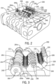
- FIGS. 2-7 depict an attachment mechanism 200 for attaching a sensor node 210 to a deployment cable 214 in the context of a deployment system on the stern deck of a marine seismic vessel.
- sensor nodes are described in U.S. Patent Application No. 15/988,668 entitled MODULAR SEISMIC NODE filed 24 May 2018 , which is incorporated by reference herein in its entirety and for all purposes.
- Suitable deployment systems are described in U.S. Patent Application No. 15/987,241entitled SEISMIC NODE DEPLOYMENT SYSTEM filed 23 May 2018 and U.S. Patent Application Publication No. US 2013/0189036 , each of which is incorporated by reference herein in its entirety and for all purposes.
- suitable sensor modules or nodes may include at least one seismic sensor configured to generate seismic data responsive to seismic waves or wavefield and a clock configured for associating the seismic data with a clock signal or othertiming signal.
- nodes may be modular and composed of two or more separable components attached together, for example, a power source module and a sensor module.
- nodes may comprise a coupling mechanism configured to mechanically engage the power source module with the sensor module and to mechanically disengage the power source module from the sensor module.
- Suitable power modules may include at least one power source and a memory with capacity for storing the seismic data and associated clock signal.
- the sensor module includes an elongate lobe or axial section extending from a base or frame component with the at least one seismic sensor.
- the modular seismic node may also include a number of additional geophones, hydrophones, accelerometers, velocity sensors, and the like.
- the attachment mechanism 200 is configured as a grip or clamping device for selectively coupling and decoupling the housing 212 of the node 210 to a rope, line, or cable 214 (see FIGS. 4-6 ).
- the clamping or attachment mechanism 200 includes a fixed part or clamp base 240 and a clamp grip 220 pivotably attached to the clamp base 240 by a hinge 234.
- the clamp base 240 may have base flanges 242 which extend from sides of the clamp base 240 and which may further define a number of mounting holes 244 therethrough.
- the mounting holes 244 may be configured to align with corresponding threaded blind holes in the node 210. Bolts (not shown) may be placed through the mounting holes 244 and fastened within the blind holes to fix the attachment mechanism 200 to the housing 212 of the node 210.
- the clamp base 240 may further be considered to have three different functional aspects defined by three structural areas, base hinge knuckles 246, a cable channel 248 for receiving the cable 214, and a latch 260 for locking the clamp grip 220 to the clamp base 240.
- the cable channel 248 is defined within the clamp base 240 as a substantially half-cylinder recess.
- a number of raised ribs 250 may be formed within the wall of the clamp base 240 defining the cable channel 248. In the exemplary embodiment shown in the figures, the ribs 250 may be arranged perpendicular to a longitudinal axis of the cable channel 248 such that they form raised arcs with wells between adjacent base ribs 250.
- the base ribs 250 may be spaced apart from each other equidistantly along the longitudinal axis of the cable channel 248. In other embodiments, spacing between the base ribs 250 may be at varied spacing patterns or at irregular spacing distances.
- the base hinge knuckles 246 may extend outwardly from one lateral edge of the clamp base 240 adjacent to and along the longitudinal length of the cable channel 248.
- the base hinge knuckles 246 each define a cylindrical through-hole therein in axial alignment with each other and parallel to the longitudinal axis of the cable channel 248.
- the base hinge knuckles 246 may be spaced apart from each other either equidistantly or at uniform spacing.
- the width of the hinge knuckles 246 may be uniform or varied.
- the latch 260 may extend outwardly from another lateral edge of the clamp base 240 adjacent to and along the longitudinal length of the cable channel 248 opposite from the base hinge knuckles 246.
- the latch 260 may be formed by a number of support blocks 252 arranged in series parallel to the longitudinal axis of the cable channel 248.
- the support blocks 252 each define a bore-hole therein in axial alignment with each other and parallel to the longitudinal axis of the cable channel 248.
- the support blocks 252 may extend substantially above a lateral edge of the half-cylinder form of the cable channel 248 as depicted in FIG. 3 .
- a latch pin 262 may extend within the through-holes of the support blocks 252 and further extend outward from each end of the outer support blocks 252 on opposing ends of the latch 260.
- the bore-holes in each of the support blocks 252 may define a cross-sectional shape substantially congruent with a cross-sectional shape of the latch pin 262.
- the latch pin 262 may be flat on three sides and curved on a fourth side.
- the latch pin 262 may be flat on all sides to define a square or rectangular cross section at its largest cross-sectional size, or it may have other cross-sectional shapes.
- the latch pin 262 may further be formed with keyways 254 therein with latch plates 268 defined on each side of each keyway 254.
- the keyways 254 may be notches formed within the interior edge of the latch pin 262.
- the keyways 254 may be sized to conform to the width of the spacing between each of the support blocks 252. In other embodiments, the keyways 254 may be wider or narrower.
- the latch plates 268 may be sized to conform to the width of the spacing between each of the support blocks 252 and, in the exemplary embodiment shown, define the largest cross-sectional are of the latch pin 262.
- the latch pin 262 may extend beyond the support blocks 252 on each end of the latch 260.
- Engagement knobs 264a/b may be affixed to each end of the latch pin 262.
- the engagement knobs 264a/b may be of any appropriate size and shape for interfacing with a device for attaching the node 210 to the cable 214.
- the engagement knobs 264a/b are toroidal or donut-shaped and are larger in diameter than the largest cross-sectional dimension of the latch pin 262.
- a pair of latch springs 266a/b are further mounted on the opposing ends of the latch pin 262 between the end support blocks 252 and the engagement knobs 264a/b.
- the latch springs 266a/b are larger in diameter than the latch pin 262 and smaller in diameterthan the engagement knobs 266a/b and the exterior surface dimensions of the end support blocks 252. In an equilibrium position as shown in FIGS. 2, 3 , and 7 , the latch springs 266a/b are of equal length and are under commensurate compression. In the equilibrium position, the latch plates 268 of the latch pin 262 are positioned in between each of the support blocks 252 while the keyways 254 are positioned within the bore holes of the support blocks 252.
- the clamp grip 220 may have a grip body 232 that supports three different functional, structural elements: a set of hinge knuckles 224, a grip channel 230 for clamping around the cable 214, and a number of latch fingers 226.
- the grip channel 230 is defined within the grip body 222 as a substantially cylindrical recess.
- a number of raised ribs 232 may be formed within the wall of the grip body 222 defining the grip channel 230.
- the ribs232 may be arranged perpendicular to a longitudinal axis of the grip channel 230 such that they form raised arcs with wells between adjacent ribs 232.
- the ribs 232 may be spaced apart from each other equidistantly along the longitudinal axis of the grip channel 230. In other embodiments, spacing between the ribs may be at varied spacing patterns or at irregular spacing distances.
- the grip hinge knuckles 224 may extend outwardly from one lateral edge of the grip body 222 adjacent to and along the longitudinal length of the grip channel 230.
- the grip hinge knuckles 224 each define a cylindrical through-hole therein in axial alignment with each other and parallel to the longitudinal axis of the grip channel 230.
- the grip hinge knuckles 224 may be spaced apart from each other either equidistantly or at uniform spacing.
- the width of the grip hinge knuckles 224 may be uniform or varied and may be sized and spaced to interface with the spaces between the base hinge knuckles 252.
- the latch fingers 226 may extend outwardly from another lateral edge of the grip body 222 adjacent to and along the longitudinal length of the grip channel 230 opposite from the hinge knuckles 224. The latch fingers 226 further extend substantially tangential to the edge of the cylindrical form of the grip channel 230 and beyond the lateral edge of the grip channel 230 as depicted in FIG. 3 .
- the terminal end of each latch finger 226 may be shaped like a boot with a surface defining latch catch 228, as shown to good advantage in FIG. 3 .
- the latch fingers 226 may be sized to fit in between the support blocks 252 of the latch 260 on the clamp base 240.
- each of the latch catches 228 may be sized and shaped to fit within a respective keyway 254 on the latch pin 262 as further described below.
- the clamp grip 220 is coupled to the clamp base 240 by interlacing the grip hinge knuckles 224 with the base hinge knuckles 246, aligning the through-holes in the grip hinge knuckles 224 with the base hinge knuckles 246, and inserting a hinge pin 234 within the through-holes in the grip hinge knuckles 224 and the base hinge knuckles 246.
- An internal hinge spring 236 may be placed on the hinge pin 234 and reside within one or more of the through-holes in the grip hinge knuckles 224 and the base hinge knuckles 246, for example, as shown in FIG. 4 .
- Some of the through-holes in the grip hinge knuckles 224 and the base hinge knuckles 246 may be of larger diameter than other through-holes in the remaining knuckles 224, 246 in order to accommodate the larger diameter of the hinge spring 236.
- the hinge spring 236 may be a torsion spring and may be biased to urge the clamp grip 220 into an open position with respect to the clamp base 240.
- Fasteners or caps may be placed upon one or both ends of the hinge pin 234 in order to retain the hinge pin 230 within the grip hinge knuckles 224 and the base hinge knuckles 246.
- the hinge pin 234 may be a bolt with a head on one end and a nut threaded on the opposing end to retain the hinge pin 234 within the grip hinge knuckles 224 and the base hinge knuckles 246.
- the attachment mechanism 200 may be used to attach a node 210 to a cable 214 by placing the cable 214 within the cable channel 248 and then rotating the clamp grip 220 about the hinge pin 234 to engage the grip channel 230 with the top surface of the cable 214.
- a node attachment device places a node 210 in alignment with a cable 214 and holds the node 210 in a fixed position.
- the node attachment device then engages either one of the engagement knobs 264a/b at either end of the latch pin 262 to force the latch pin 262 in one direction or the other. With such engagement, the latch springs 266a/b are biased in compression and extension, respectively, as indicated in FIG. 5 . In this position, the keyways 254 of the latch pin 262 are further aligned with the spaces between each of the support blocks 252.
- the node attachment device pivots the clamp grip 220 about the hinge pin 234, overcoming the bias of the hinge spring 236, and positions the clamp grip 220 over the cable 212 such that the cable is sandwiched between the clamp grip 220 and the clamp base 240 within the cable channel 248 and the grip channel 230.
- the latch fingers 226 extend between the support blocks 252 and through the keyways 254 in the latch pin 262 such that the latch catches 228 are at a level beneath the latch pin 262 as shown in FIG. 6 .
- the node attachment device then releases the engagement knobs 264a/b of the latch 260 and the latch springs 268 force the latch pin 262 back to its equilibrium position such that the latch plates 268 are positioned between the support blocks 252 and over the latch catches 228.
- the latch fingers 226 are retained by the latch pin in the clamp base 240 (as shown in in FIG. 7 ), the cable 214 is clamped within the attachment mechanism 200, and the node 210 is attached to the cable 214.
- the attachment mechanism 200 may be formed of molded plastics and corrosion resistant metals depending upon the application and environment for deployment. In other embodiments, the attachment mechanism can be made of molded or machined metals (e.g., steel). In some exemplary embodiments, the clamp may be able to withstand a force of between 500-1000 lb. (2225-4449 N) in each direction (including longitudinal shear) and withstand breaking under a load of up to 2000 lb. (8898 N) in any direction.
- the grip ribs 232 and base ribs 250 may aid in providing a strong frictional grip along the cable 214 in resistance to shear forces.
- the cable 214 can be formed of a suitable synthetic rope or cable material, from natural fibers, from a wire cable or other metal material, or from a combination thereof.
- the cable 214 can be configured for deploying one or more seismic nodes 210 to the ocean floor, or for towing one or more seismic nodes 210 through a water column.
- the cable 214 is formed solely of a passive strength component, while in other embodiments the cable 214 includes power and data lines for communication with individual nodes 210 attached to the cable 214.
- the diameter of the grip channel 230 and the cable channel 248 may be designed to accommodate different diameters of cable 214 (e.g., 1 ⁇ 2 in. (12.5 mm) or 3 ⁇ 4 in. (19 mm)). Additionally, if the cable 214 is a synthetic woven rope or other material of lower density, the grooves between the ribs 232, 250 provide space for such compressed materials to escape and further provide a structural interlock between the cable 214 and the attachment mechanism 200.
- device with a larger diameter grip channel 230 and cable channel 248 may be modified with inserts to reduce the diameters of the a larger diameter grip channel 230 and cable channel 248 to accommodate a smaller diameter cable 214.
- inserts may be ribbed in order to mechanically and frictionally interface with the grip channel 230 and cable channel 248 and similarly provide ribs on the opposing side to interface with the cable 214.
- the node attachment device may be switch to a detachment mode.
- the node attachment device will capture the node and hold it in a fixed position to engage the engagement knobs 264a/b in order to bias the latch pin 262 in an open position.
- the latch pin 262 By moving the latch pin 262 longitudinally, the latch plates 268 are moved off the latch catches 228 and the keyways 254 are positioned over the latch fingers 226, thereby allowing the latch fingers to release from the latch 260.
- the hinge spring 236 is arranged to bias the clamp grip 220 in an open position
- the clamp grip 220 will spring open and release the cable 214 from within the base channel 248 and grip channel 230.
- the node attachment device then releases the engagement knobs 164a/b and the latch springs 166a/b return to their equilibrium position such that the latch plates 268 are positioned between the support blocks 252.
- the node attachment device then removes the node 210 from the work area as further described below.
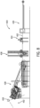
- FIG. 8 is a schematic depiction of major components of a modular node deployment system 400 configured for implementation on the aft deck of a marine vessel.
- the system 400 may have particular utility in attaching sensor nodes to a cable 402 for deployment off the stern of the marine vessel into a body of water, e.g., for seismic survey purposes.
- the cable 402 may be stored on and unwound from one or more storage spools (not shown).
- the cable 402 may first pass through a forward buffer system 406 to help control the speed of the cable 402 as it passes through a node attachment-detachment station 404.
- the cable 402 travels through an aft buffer system 408, which operates in conjunction with the forward buffer system 406 to control the speed of the cable 402 during attachment or detachment of a nose in the attach-detach station 404.
- aft buffer system 408 operates in conjunction with the forward buffer system 406 to control the speed of the cable 402 during attachment or detachment of a nose in the attach-detach station 404.
- an overboarding unit 428 is positioned at the stern of the marine vessel to pay out and take up cable from the body of water.
- the structure and control of the overboarding unit 428 may be specifically designed to avoid damage to nodes attached to the cable 902 as the nodes pass through the overboarding unit 428. Particular implementations of such overboarding units 428 are described in further detail below.
- a position sensing device 450 may be incorporated to operate in conjunction with the overboarding system 428 for the purpose of identifying the position of a node within a field of view 452 with respect to the overboarding system 428 during retrieval of the cable 402 in order to provide precise control signals to the overboarding unit 428. Integration of such position sensing devices 950 with the overboarding unit 428 are discussed in greater detail below.
- FIGS. 9A-10C An implementation of a seismic node deployment system 500 similar to that of FIG., 8 is depicted schematically in FIGS. 9A-10C .
- the system 500 is configured to attach and detach a plurality of seismic receiver nodes 510 onto and from a cable 502 for deployment from and return to a marine vessel.
- Nodes 510 can be seismic nodes, receivers, or other autonomous sensing devices, or, alternatively or in addition, acoustic pingers or other transponders for location identification or other information transmission attached at positions spaced apart along the cable 502.
- the system 500 may include a forward buffer system 506 and an aft buffer system 508 for controlling the relative speed of the cable 502 with respect to a node coupling device 504 for attachment and detachment of a plurality of nodes 510 to the cable 502 in spaced apart locations.
- the forward and aft buffer systems 506, 508 may periodically temporarily divert portions of the cable 502 to take up and pay out sections of the cable 502 to reduce the speed of a portion for node attachment.
- the periodic diversions of the cable 502 in the forward and aft buffer systems 506, 508 may be at regular intervals. In other embodiments, the periodic diversions may occur at intermittent intervals with no fixed or regular time frame between occurrences, but rather occur upon a command to signal to attach or detach a node 510 to or from the cable 502.
- the cable 502 may be stored upon a storage winch or spool 512 from which the cable 502 is payed out for deployment in the water column or wound around for storage when not in use.
- a traction winch or cable tensioner 514 may be positioned between the forward buffer system 506 and the aft buffer system 508 in order to maintain appropriate tension on the cable 502 as it is payed out or hauled in.
- the node coupling device 504 may be positioned between the cable tensioner 514 and the aft buffer system 508.
- the forward buffer system 506 may include a forward pinion pulley 514 that travels laterally on a lateral rack 516.
- a drive motor may be attached to the forward pinion pulley 514 and configured to move the forward pinion pulley 514 back and forth along the lateral rack 516.
- the aft buffer system 508 may include a first aft base pulley 520 and a second aft base pulley 522 both fixedly positioned adjacent to the base of a vertical rack 528.
- the first aft base pulley 520 may be positioned on a forward side of the vertical rack 528 and the second aft base pulley 522 may be positioned on an aft side of the vertical rack 526.
- An aft pinon pulley 524 may be movably attached to the vertical rack 526 and aligned between the first and second aft base pulleys 520, 522.
- a drive motor may be attached to the aft pinion pulley 524 and configured to move the aft pinion pulley 524 up and down along the vertical rack 526.
- FIGS. 9A-9D An exemplary deployment operation of the system 500 is depicted in the series of FIGS. 9A-9D .
- the cable 502 must be unwound from the spool 512 and threaded through the components.
- the spool 512 may be manually driven while threading the cable 502 through the system 500, i.e., through the forward buffer system 506, the cable tensioner 514, the node coupling device 504, the after buffer system 508, and through an overboarding unit (not shown in the schematics of 9A-9D).
- An end weight may be connected to the first end of the cable 502, typically using a deck crane (not shown).
- the cable 502 is unwound from storage on the spool 512 and is threaded around the forward pinion pulley 516.
- the spool 512 is typically driven by a motor and functions as a winch when both coiling and uncoiling the cable 502 from the spool 512 due to the significant mass of the cable 502 and the related moment generated while the spool 512 rotates.
- the spool 512 provides tension on the cable 512 as it pays out.
- the forward pinion pulley 516 is movably mounted on the lateral rack 518 and may be driven laterally along the lateral rack 518 by a motor (not shown) that is under control of a control system as further described herein.
- the lateral rack 518 may include a linear array of gear teeth along its length and the motor may turn a gear that interfaces with the linear gear teeth to move the forward pinion pulley 516 back and forth on the lateral rack 518.
- the cable tensioner 514 may be composed of one or more pulleys through which the cable 502 passes and which are configured to provide appropriate tension on the cable 502 when deploying and retrieving the cable 502 from the water column.
- the one or more of the pulleys forming the cable tensioner 514 may be motor-driven with appropriate transmission gearing in order to protect the forward pinion pulley 516 and the spool 512 from excessive force that may be placed on the cable 502 by the water column.
- each node 510 may be equipped with an attachment mechanism (e.g., the attachment mechanism 200 of FIGS. 2-7 ) that clamps the node 510 onto the cable 502.
- the node coupling device 504 may be configured to pick a node 510 with an attachment mechanism from a provided supply of nodes 510, place the attachment mechanism on the node 210 adjacent to the cable 502, compress a latch spring to open a latch on the attachment mechanism, close a clamp of the attachment mechanism about the cable 502, and release the latch spring to close the latch and secure clamp about the cable 502 to connect the node 510 to the cable 502.
- the cable 502 may be threaded through a number of pulleys forming the aft cable buffer 508.
- the first aft base pulley 520 and the second aft base pulley 522 may be located at fixed positions on lateral sides of the base of the vertical rack 526 along which the aft pinion pulley 524 moves.
- the aft pinion pulley 524 may be driven vertically along the vertical rack 526 by a motor (not shown) that is under control of a control system as further described herein.
- the vertical rack 526 may include a linear array of gear teeth along its length and the motor may turn a gear that interfaces with the linear gear teeth to move the aft pinion pulley 516 up and down on the vertical rack 526.
- the cable 502 may pass under each of the first aft base pulley 502 and the second aft base pulley 522 and pass over aft pinion pulley 516.
- the aft pinion pulley 516 may pass between each of the first aft base pulley 502 and the second aft base pulley 522 to a low point of its vertical travel and disengage from contact with the cable 502.
- the cable 502 with attached nodes 510 may be deployed into the water column via an overboarding unit (not shown).
- the selected spool 512 will enter into a tension mode, and the cable tensioner 514 will start pulling out cable 502 from the spool 512 at a cable speed synchronized with the vessel speed.
- the aft buffer 508 will accumulate a maximum amount of cable length by moving to its upper position.
- the aft buffer 508 will start paying out from the accumulated length, thereby keeping a steady cable speed paying out from the vessel.
- the forward buffer 506 will start accumulating cable by moving forward, and thereby keep a steady cable speed out from the spool 512.
- the forward buffer 506 will stop, and the cable 502 with a node 510 connected will move toward the overboard unit.
- the forward buffer 506 will move to its aft position and the aft buffer 508 will start accumulating cable at a synchronized speed.
- the system 500 is ready for attaching another node 510.
- FIGS. 9A-9D A configuration and operation for deployment of the cable 502 and attachment of the nodes 510 as generally described above is shown in greater detail in FIGS. 9A-9D .
- the forward pinion pulley 516 begins in an aft position along the lateral rack 518 and the aft pinion pulley 524 begins in an upper position on the vertical rack 526.
- the cable tensioner 514 starts pulling cable at a constant speed.
- the cable 502 is unwound from the spool 512 such that it travels linearly at a constant velocity V.
- the linear velocity of the cable 502 may be up to 5 knots (2.5 m/s).
- the forward pinion pulley 516 begins moving forward on the forward rack 518 at a speed of substantially 1 ⁇ 2V to thereby take up the length of cable 502 unwinding from the spool 512.
- the aft pinion pulley 524 begins moving downward on the vertical rack 526 at a speed of substantially 1 ⁇ 2V to thereby pay out the cable 502 previously extended along the vertical rack 526 to be overboarded at a velocity V.
- the relative speed of the cable 502 with respect to the node coupling device 504 is 0V, i.e., the portion of the cable 502 passing through the node coupling device 504 is effectively not moving in that reference frame.
- the node 510 can be easily attached to the desired location on the cable 502 during the time it takes the forward and aft pinion pulleys 516, 524 to traverse lengths of the lateral and vertical racks 518, 526, respectively.
- the time for such traversal is on the order of several seconds depending upon the length of the racks 518, 526 and the speed of the cable 502, e.g., if the overboarding velocity V is 5 knots (2.5 m/s).
- the node coupling device 504 to pick a node 510 from a supply, place the clamp of an attachment mechanism around the cable 502, compress a latch spring to open a latch on the attachment mechanism, close a clamp of the attachment mechanism about the cable 502, and release the latch spring to close the latch and secure clamp about the cable 502 to connect the node 510 to the cable 502.to complete the attachment of the node to the cable 502.
- the forward and aft pinion pulleys 516, 524 have completed their traverse of the lateral and vertical racks 518, 526, respectively.
- the aft pinion pulley 524 is positioned below the first and second aft base pulleys 520, 522 as shown in FIG. 9C and is no longer in contact with the cable 502.
- the forward and aft pinion pulleys 516, 524 are stationary in the forward and bottom positions on the lateral and vertical racks 518, 526, respectively, the cable 502 continues to be pulled by the cable tensioner 514 and travels through the entire system 500 at the full, constant deployment speed V.
- the coupled node 510 is attached to extend from the bottom of the cable 502. In this manner, the node 510 does not interfere with either of the first and second aft base pulleys 520, 522, nor does the node 510 interfere with the aft pinion pulley 524, which is positioned at a sufficient distance beneath the path of the cable 502 for clearance of the node 510 over the top of the aft pinion pulley 524. Also at this time, a new node 510' may be placed within the node coupling device 504 in a position for picking and placement of the new node 510' on the cable 502.
- the forward and aft pinion pulleys 516, 524 begin traveling along the lateral and vertical racks 518, 526, respectively, typically at a speed of 1 ⁇ 2V, to their starting positions at the forward and top positions on the lateral and vertical racks 518, 526, respectively, as shown in FIG. 9D .
- the cable 502 maintains its overboarding speed of V at the stern of the marine vessel as the forward and aft pinion pulleys 516, 524 move.
- the cable 502 is payed out at velocity V along its length until the control system for the seismic node deployment system 500 determines that the desired separation distance between nodes 510 is reached and the attachment cycle begins again as described above beginning with FIG. 9A .
- the velocity V of the cable 502 unwinding from the spool is the same as the velocity V of the cable 502 when overboarding off the stern of the marine vessel into the water column and the this velocity V remains constant throughout the cable deployment process.
- FIGS. 10A-10C depict a node detachment process performed by the seismic node deployment system 500.
- the aft buffer 508 will be in lower or "open" position
- the cable tensioner 514 will reel the cable 502 in at a synchronized speed with the vessel.
- the spool 512 will be in a tension mode rotating in an opposite direction to wind up the cable 502.
- Sensors will detect when a node 510 approaches the node coupling device 504.
- the aft buffer 508 When a node 510 reaches the correct position in the node coupling device 504, the aft buffer 508 will start accumulate cable 502 at a synchronized speed with the vessel, thereby keeping a steady cable take up speed out of the water. Simultaneously, the forward buffer 506 will start moving backwards at the same speed, thereby keeping the node 510 at a steady position in the node coupling device 504 for long enough to disconnect the node 510 from the cable 502. When the node 510 is disconnected, the forward buffer 506 will move forward toward its center position, and the aft buffer 508 will move toward its lower or "open" position. As soon the aft buffer reaches the "open" position, the system 500 is ready for receiving the next node 510.
- the aft pinion pulley 524 is positioned on the vertical rack 526 below the first and second aft base pulleys 520, 522 (as shown in FIG. 10A ) and is no longer in contact with the cable 502.
- the forward pinion pulley 516 is additionally in the fully forward position on the lateral rack 518. While the forward and aft pinion pulleys 516, 524 are stationary in the forward and bottom positions on the lateral and vertical racks 518, 526, respectively, the cable 502 may be reeled in or onboarded through the system 500 at the full deployment speed V. As shown in FIG.
- the coupled node 510 is attached to extend from the bottom of the cable 502. In this manner, the node 510 does not interfere with either of the first and second aft base pulleys 520, 522, nor does the node 510 interfere with the aft pinion pulley 524, which is positioned at a sufficient distance beneath the path of the cable 502 for clearance of the node 510 over the top of the aft pinion pulley 524.
- the control system causes the forward and aft pinion pulleys 516, 524 begin traveling along the lateral and vertical racks 518, 526, respectively, typically at a speed of 1 ⁇ 2V, to halt the node 510 at the node coupling device 504.
- the cable section in front of the node coupling device 504 is stationary relative to the node coupling device 504, the cable 502 maintains an onboarding speed of V at the stern of the marine vessel and similarly a spooling speed of V as the forward and aft pinion pulleys 516, 524 move.
- the node 510 can be easily detached from the cable 502 as indicated in FIG. 10B during the time it takes the forward and aft pinion pulleys 516, 524 to traverse lengths of the lateral and vertical racks 518, 526, respectively.
- the time for such traversal is on the order of several seconds, e.g., if the overboarding velocity V is 5 knots (2.5 m/s).
- the forward pinion pulley 516 begins to move forward from an aft position along the lateral rack 518 and create a buffer length of cable 502 for continuous, constant velocity take up by the spool 512.
- the aft pinion pulley 524 begins to simultaneously move downward from the upper position on the vertical rack 526 to relinquish its buffer length of cable 502, which is thus transferred to the forward buffer system 506.
- the forward and aft pinion pulleys 516, 524 ultimately return to their starting positions for node detachment during retrieval of the cable 502 such that the next node can pass by the aft pinion pulley 524 to be positioned in the node coupling device 504, at which point the cycle repeats.
- the cable 502 winds onto the spool 512 at a constant velocity V, which is the same as the take-up velocity of the cable 502 from the water column.
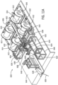
- FIGS. 9A-10C An exemplary implementation of a seismic node deployment system 600 according to the schematic diagrams in FIGS. 9A-10C is depicted on the back deck 644 of a marine vessel in FIGS. 11A-11B .
- the system 600 is configured to attach and detach a plurality of seismic receiver nodes 610 onto and from a cable 602 for deployment from and return to a marine vessel.
- the system 600 may include a forward buffer system 606 and an aft buffer system 608 for controlling the relative speed of the cable 602 with respect to a node coupling device 610.
- a number of cables 602 may be stored upon a number of spools 612 from which the cables 602 are payed out for deployment in the water column or wound around for storage when not in use.
- a cable tensioner 614 may be positioned between the forward buffer system 606 and the aft buffer system 608 in order to maintain appropriate tension on the cable 602 as it is payed out or hauled in.
- the node coupling device 604 may be positioned between the cable tensioner 614 and the aft buffer system 608.
- the cable 602 As the cable 602 is unwound from storage on one of the spools 612, it may pass around a pulley on a spooling device 632 that aids in uncoiling and coiling the cable 602 on the spools 612.
- the spool 612 is typically driven by a motor and functions as a winch when both coiling and uncoiling the cable 602 from the spool 612 due to the significant mass of the cable 602 and the related moment generated while the spool 612 rotates.
- the pulley on the spooling device 632 travels laterally on a bar to follow the position of the cable 602 as it unwraps or wraps around the spool 612.
- the pulley on the spooling device 632 directs the cable 602 from between the spools 612 to the forward buffer system 606 where the cable 602 and is threaded around the forward pinion pulley 616.
- a number of additional fixed forward guide pulleys 634 may additionally be used to direct the cable 602 along the forward buffer system 606 to the forward pinion pulley 616.
- the lateral rack 618 may include a linear array of gear teeth along its length and the motor may turn a gear that interfaces with the linear gear teeth to move the forward pinion pulley 616 back and forth on the lateral rack 618.
- the cable tensioner 614 may be composed of one or more pulleys about which the cable 602 is threaded and which are configured to provide appropriate tension on the cable 602 when deploying and retrieving the cable 602 from the water column.
- the pulleys may include a motor-driven tension drive pulley 640 and a number of tension guide pulleys 642.
- the tension drive pulley 640 may have transmission gearing in order to protect the forward pinion pulley 616 and the spool 612 from excessive force that may be placed on the cable 602 by the water column.
- the cable 602 next passes through the node coupling device 604, which is configured to attach a plurality of sensor nodes 610 serially onto the cable 602, typically at fixed interval spacings (and to further detach the nodes 610 from the cable 602 in an opposite operation).
- the nodes 610 may be conveyed to the node coupling device 604 from storage areas on the marine vessel via a conveyor system 636.
- the nodes 610 may be designed to separate into two separate components, for example, a battery/memory component and a sensor/clock component, that are uncoupled from each other for storage and maintenance.
- the system 600 may include pinning and unpinning stations 638 adjacent to the node coupling device 604 to couple the node components together before attachment of the nodes 610 to the cable 602 or to separate the node components after the nodes 610 are removed from the cable 602.
- the node 610 may be equipped with a coupler that clamps the node 610 onto the cable 602.
- the node coupling device 604 may be configured to pick a node 610 from a provided supply of nodes 610, place the coupler adjacent to the cable 502, compress a latch spring to open a latch on the attachment mechanism, close a clamp of the coupler about the cable 502, and release the latch spring to close the latch and secure coupler about the cable 502 to connect the node 510 to the cable 502.to connect the node 610 to the cable 602.
- the cable 602 may be threaded through a number of pulleys forming the aft cable buffer 608.
- the first aft base pulley 620 and the second aft base pulley 622 may be located at fixed positions on lateral sides of the base of the vertical rack 626 along which the aft pinion pulley 624 moves.
- the aft pinion pulley 624 may be driven vertically along the vertical rack 626 by a motorthat is under control of a control system 650.
- the vertical rack 626 may include a linear array of gear teeth along its length and the motor may turn a gear that interfaces with the linear gear teeth to move the aft pinion pulley 616 up and down on the vertical rack 626.
- the control system 650 may further control the forward buffer system 606, the spools 512, the cable tensioner 614, the node coupling device 6040, and other components of the system 600 in order to synchronize components and balance forces and loads on the system 600.
- the overboarding unit 628 may include additional guide pulleys and provide a strong, structural framework for guiding the cable 602 over the stern of the marine vessel and into the water column.
- the pressure washer unit 648 may be used to clean salt water, mud, and debris from the nodes 610 and other components in order to maintain and extend the life of such components.
- the deck crane 646 may be used to move, assemble, or disassemble any of the components of the system 600 on the back deck 644.
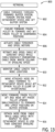
- FIG. 12 A flow diagram with exemplary node deployment operations 700 undertaken by a control system to coordinate such a seismic node deployment system is presented in FIG. 12 .
- the cable must be routed from storage on the spool through the forward buffer system, the tension system, the node coupling device, and the aft buffer system as indicated in starting configuration status 702.
- the control system will actuate the motor on the spool to pay out the cable at a constant speed as indicated in operation 704.
- control system will actuate the motor of the driven pulley in the cable tensioner to place appropriate tension on the cable within the system as indicated in operation 706.
- control system constantly monitors and adjusts the power to and effects gear changes in transmissions of the spool motor and cable tensioner motor in order to maintain proper tension on the cable and resist constantly changing forces on the cable, for example, forces of the moment of the cable mass as the spool rotates and forces from the water column dragging on cable length that is already deployed from the marine vessel.
- the control system further monitors the length of cable payed out from the spool as indicated in operation 708 in order to identify the locations for node placement along the cable.
- the nodes will be and attached at equal separation distances along the cable.
- the control system can be programmed to attach the nodes to the cable at disparate separation distances as desired in orderto meet any particular seismic recording requirements.
- the control system actuates the motors that move the forward and aft pinion pulleys on the racks. The forward pinion pulley is moved forward and the aft pinion pulley is moved downward simultaneously at substantially half the speed that the cable is payed out from the spool.
- the cable segment located at the node coupling device is substantially stationary or moves at a significantly reduced speed with respect to the node coupling device for the period that the forward and aft pinion pulleys traverse the racks.
- the control system causes the node coupling device to attach the node to the cable as indicated in operation 712.
- the control system can control the time available for attachment of the nodes on the order of several seconds depending upon the length of the racks and the speed of the cable. This is adequate time for the node coupling device to pick a node from a supply, compress the spring clamp, place the open clamp around the cable, and release the spring clamp on the node to complete the attachment of the node to the cable.
- the control system may further control and coordinate the conveyor system to deliver nodes to the node coupling device and position them for picking by the node coupling device.
- the control system further monitors the position of the aft pinion pulley on the vertical rack to determine when its position is below the aft base pulleys and clear of the cable and attached node as indicated in operation 714. Once the aft pinion pulley reaches this bottom position, its movement is halted by the control system and the cable moves at a constant speed throughout the entire deployment system to pass the aft buffer system with the attached node and continue to the overboarding unit for deployment into the water column as indicated in operation 716.
- the speed of the cable is traveling through the deployment system is constant with respect to all components of the system at this point (i.e., the speed of the cable coming off the spool is the same as the speed of the cable with respect to the node coupling device, which is the same as the speed of the cable entering the watercolumn).
- the control system actuates the motor on the forward pinion pulley to move it aft and the motor on the aft pinion pulley to move it upward as indicated in operation 718. In this manner, the forward and aft pinion pulleys return to their starting locations on the racks to prepare the deployment system to attach the next node.
- FIG. 13 is a flow diagram depicting exemplary retrieval operations 800 undertaken by a control system to coordinate such retrieval of a seismic node deployment system from a water column.
- the cable in order for the retrieval operation to begin, the cable must be attached to a spool and threaded through the forward buffer system, the tension system, the node coupling device, and the aft buffer system as indicated in starting configuration status 802.
- the control system next determines whether the forward and aft pinion pulleys are in the proper starting positions for node retrieval and removal, which are the forward and downward positioned, respectively, as indicated in operation 804. If the forward and aft pinion pulleys are not is the proper positions, the control system actuates the motors that move the forward and aft pinion pulleys on the racks to the proper positions.
- control system will actuate the motor on the spool to coil the cable at a constant speed as indicated in operation 806.
- the control system will actuate the motor of the driven pulley in the cable tensioner to place appropriate tension on the cable within the system as further indicated in operation 806.
- the control system After actuation of the spool and cable tensioner, the control system constantly monitors and adjusts the power to and effects gear changes in transmissions of the spool motor and cable tensioner motor in order to maintain proper tension on the cable and resist constantly changing forces on the cable, for example, forces of the moment of the cable mass as the spool rotates and acquires more cable mass and forces from the water column dragging on changing cable length that is in the water column.
- the control system further maintains a constant speed of the spool for retraction of the cable from the water column at the same constant speed as indicated in operation 808.
- the control system may further coordinate the rotational speed of the driven pulley in the tensioner system to draw the cable through the tensioner system at the same speed of coiling on the spool. While the cable is coiled, the control system further monitors the length of cable retrieved from the water column as indicated in operation 708 in order to identify the locations of the nodes for positioning within the node coupling device for node removal from the cable.
- the nodes will be and attached at equal separation distances along the cable. However, the nodes may be attached to the cable at disparate separation distances as desired in order to meet any particular seismic recording requirements.
- the control system may merely monitor for the presence and location of a node as it passes through the components of the deployment system on the back deck.
- the control system specifically determines when a node has passed the aft buffer system and is in line with the node coupling device as indicated in operation 812. At this point, the forward pinion pulley is moved aft and the aft pinion pulley is moved upward simultaneously at substantially half the coiling speed of the cable onto the spool as indicated in operation 814.
- the cable segment with the attached node located at the node coupling device is substantially stationary or moves at a significantly reduced speed with respect to the node coupling device for the period that the forward and aft pinion pulleys traverse the racks.
- the node By effectively halting the movement of the cable through the node coupling device, the node can be easily detached from the cable as indicated in operation 816 during the time it takes the forward and aft pinion pulleys to traverse lengths of the lateral and vertical racks, respectively. Typically the time for such traversal is on the order of several seconds. This is adequate time for the node coupling device to grasp the node on the cable, compress the spring clamp, remove the open clamp from around the cable, release the spring clamp on the node, and deposit the node for storage or maintenance activities.
- the control system returns them to their starting positions to await the next node while the cable continues to be reeled in from the water column and stored on the spool at a constant speed.
- FIGS. 14-16 depict an exemplary embodiment of an overboard unit 928 positioned at the stern of the marine vessel for paying cable 902 with attached nodes 910 into the water and retrieving the cable 902 with attached nodes 910 from the water without damaging the nodes 910.
- the overboard unit 928 may include two or more rotary sheaves 906 and a rotary support frame 907 for carrying the sheaves 906.
- the term "sheave” as used herein refers to a pulley or wheel or roller with a groove along its edge for guiding a cable while changing the running direction of the cable.
- the support frame 907 is substantially square in shape and four rotary sheaves 906 are attached at respective corners of the support frame 907 as further described below.
- the sheaves 906 are spaced from each other a distance that is greater than a length of the nodes 910 to permit the cable 902 with the attached node 910 to be positioned between and extend in a straight line between two adjacent sheaves 906.
- Each sheave may have a rotational axis 906'that is parallel to a rotational axis 907' of the support frame 907.
- a bracket or arm 908 is mounted to the stern of the marine vessel for carrying the rotary support frame 907.
- the sheaves 906 are configured on the support frame 907 to have an effective radius of curvature that is largerthan a minimum permissible bend radius of the cable 902 in orderto prevent damage to the cable 902 during deployment and retrieval.
- the support frame 907 is rotary at least between a first position in which the node 910 along a length of the cable 902 has a generally horizontal orientation and is supported by the two sheaves 906, and a second position in which the node 910 with the associated length of the cable 902 on each side of the node 910 extending to the sheaves 906 has a generally vertical orientation.
- the support frame 907 may actually start rotating before a node 910 reaches a sheave 906 in order to prevent the node 910 from impacting the sheave 906.
- the node 910 will be positioned between two sheaves 906 as the side of the support frame 907 receiving the node 910 is on an angularly upward trajectory and before the side of the support frame 907 with the node 910 reaches a horizontal position. During the rotation of the support frame 907, the node 910 does not move in relation to the two sheaves 906 that the node 910 is positioned between and the node 910 is continuously supported by the sheaves 906.
- the support frame 907 may be a straight arm.
- Two sheaves 906 may be located at opposing ends of the arm and the arm can rotate around its center.
- the bracket 908 will project rearward from the stern of the marine vessel to permit the arm to rotate at least a quarter of a full turn from a generally horizontal or slightly inclined orientation to a generally vertical one, or the other way around.
- the arm may swing back to its original position for receiving the next straight section of cable 902 and repeating the action.
- the arm instead of being straight, may be angular, and the two halves of the arm may form a straight angle, for example, between them.
- the support frame 907 has four sheaves 906 located at the corners of a square. As shown, the support frame 907 has four spokes 909 extending between a hub 904 and a surrounding generally square frame 911. The corners of the square support frame 907 may be beveled to give the support frame 907 an octagonal shape and the four rotary sheaves 906 are mounted at the beveled corners. As shown in FIG. 16 , the sheaves 906 are provided with a circumferential groove 912 fitting the cable 902 that engages the sheaves 906.
- two identical arms having rotary sheaves 906 at their ends may cross each other perpendicularly to form a substantially square rotary support frame having the sheaves 906 located in the corners of the square.
- the two arms may be interconnected by struts in order to increase stability.
- the sheaves 906 are preferably equidistantly spaced from the rotational axis 907' of the rotary frame 907 and equiangularly spaced from one another.
- all rotations of the support frame 907 e.g., a quarter of a full turn or slightly more
- the rotary support frame 907 may be mounted in bearings 913 in the hub 904 carried by a forked end of the bracket 908. In such a configuration, the bracket 908 may not need to project rearward from the stern of the marine vessel for adequate clearance.
- the support frame 907 can rotate around its own center on the bearings 913, and the sheaves 906 at the corners of the frame 907 can rotate freely.
- a locking system may also be employed to keep the support frame 907 from rotating when it should not.
- the locking system may be a purely mechanical device, or it can be an electrical or hydraulic system.
- FIGS. 17A-17D depict a sequence of side views of the overboard unit 928 in operation.
- the cable 902 passes over the overboard unit 928 as shown in FIG. 17A .
- the cable 902 pays out over the upper left sheave 906, which rotates while the support frame 907 is prevented from rotating by the locking system. Only the small friction force between the cable 902 and the sheave 906 will assert any rotational force on the support frame 907; all other forces are balanced and the force needed to keep the support frame 907 from rotating is small.
- a stiff node 910 When a stiff node 910 reaches the overboard unit 928, it will reach a position halfway between the two upper sheaves 906, as shown in FIG. 17B . At this point the locking system is released, and the support frame 907 can rotate freely with no relative movement between the node 910 and the support frame 907. In other embodiments the support frame 907 may have a start position at a slight inclination such that the node 910 is actually received and positioned between the upper and lower right sheaves 906 and then the support frame 907 begins to rotate. In this manner, the node 910 will not impact any of the sheaves 906 as the cable is payed out over the overboard unit 928. With this configuration, the support frame 907 rotates with the cable 902 and the node 910 is protected from any bending or other stress forces as shown in FIG. 17C .
- the locking system is engaged again, preventing the support frame 907 from rotating any more.
- the cable 902 now can continue rolling over the upper left-hand sheave 906 as shown in FIG. 17D until the next node 906 arrives at the overboard unit 928.
- the onboarding unit 928 is operated in the opposite rotational direction to ensure that the nodes 910 fall between the sheaves 906 to prevent damage to the nodes 910.
- FIG. 18 An alternate embodiment of the overboarding unit 928 is depicted in FIG. 18 .
- the overboarding unit 928 is paired with a position sensing device 950 positioned at the stern of the marine vessel and oriented with a field of view 952 to capture the nodes 910 as they emerge from the water and approach the overboarding unit 928 functioning in an onboarding mode.
- the purpose of positional sensing of the nodes 910 by the position sensing device 950 is to accurately determine the position of the node 910 and, more importantly, the distance of the node 910 from the top rear sheave 906 of the overboarding unit 928.
- the position sensing device 950 can send a control signal to the overboarding unit 928 to engage a motor that drives the hub 904 or to release a lock on the bearing 913 to begin rotation of the support frame 907 on the bearing 913,
- the node 910 will be positioned between the upper and lower rear sheaves 906 as shown in FIG. 18 when the support frame 907 begins rotating. Further, while the support frame 907 rotates, the nodes 910 will remain stationary with reference to the sheaves 906 on the support frame 907 until the node passes the position of the upper forward sheave 906 as shown in FIG. 18 . In this manner, the nodes 910 will not be pulled over or otherwise impact the sheaves 906 and thus, the likelihood of damage to the nodes 910 due to contact with the overboarding unit 928 during cable 902 and node 904 retrieval is minimized.
- the position sensing device 950 may be a stereoscopic camera with a three-dimensional field of view. The ability to perceive depth with such a camera arrangement provides for more precise measurement of position of the nodes 910 with respect to other structures. For example, some stereoscopic cameras have measurement precision to within 5 cm at up to 3 m distance of the camera from the object in the field of view.
- the position sensing device 950 may be a standard camera or video camera used in conjunction with a control system that can analyze images of the node 910 with respect to one or more known reference marks within the field of view 952.
- the control system can interpret the position of the node 910 with respect to the reference marks to calculate a precise position of the nodes 910 and provide appropriate control triggers to the overboarding unit 928.
- a laser curtain generator could be used as the position sensing device 950 and reflections from a node 910 with a field of the laser curtain can be received and interpolated through calculation into precise positional measurements of the node 910 for triggering the rotation of the support frame 907 in the overboarding unit 928.
- a proximity sensor or a motion sensor may also be integrated with a control system for the overboarding unit 928 to provide appropriate control commands to the overboarding unit 928 during onboarding of the cable 902.
Landscapes
- Life Sciences & Earth Sciences (AREA)
- Physics & Mathematics (AREA)
- Engineering & Computer Science (AREA)
- Remote Sensing (AREA)
- General Life Sciences & Earth Sciences (AREA)
- Environmental & Geological Engineering (AREA)
- Geology (AREA)
- Acoustics & Sound (AREA)
- General Physics & Mathematics (AREA)
- Geophysics (AREA)
- Oceanography (AREA)
- Radar, Positioning & Navigation (AREA)
- Chemical & Material Sciences (AREA)
- Combustion & Propulsion (AREA)
- Mechanical Engineering (AREA)
- Ocean & Marine Engineering (AREA)
- Geophysics And Detection Of Objects (AREA)
- Apparatus For Radiation Diagnosis (AREA)
- Clamps And Clips (AREA)
Applications Claiming Priority (3)
| Application Number | Priority Date | Filing Date | Title |
|---|---|---|---|
| US201862682728P | 2018-06-08 | 2018-06-08 | |
| PCT/US2019/036424 WO2019237127A2 (en) | 2018-06-08 | 2019-06-10 | Sensor node attachment mechanism and cable retrieval system |
| EP19734570.5A EP3802309B1 (de) | 2018-06-08 | 2019-06-10 | Befestigungsmechanismus für einen sensorknoten und kabelrückholsystem |
Related Parent Applications (2)
| Application Number | Title | Priority Date | Filing Date |
|---|---|---|---|
| EP19734570.5A Division EP3802309B1 (de) | 2018-06-08 | 2019-06-10 | Befestigungsmechanismus für einen sensorknoten und kabelrückholsystem |
| EP19734570.5A Division-Into EP3802309B1 (de) | 2018-06-08 | 2019-06-10 | Befestigungsmechanismus für einen sensorknoten und kabelrückholsystem |
Publications (1)
| Publication Number | Publication Date |
|---|---|
| EP4354680A2 true EP4354680A2 (de) | 2024-04-17 |
Family
ID=67108153
Family Applications (2)
| Application Number | Title | Priority Date | Filing Date |
|---|---|---|---|
| EP19734570.5A Active EP3802309B1 (de) | 2018-06-08 | 2019-06-10 | Befestigungsmechanismus für einen sensorknoten und kabelrückholsystem |
| EP24160101.2A Pending EP4354680A2 (de) | 2018-06-08 | 2019-06-10 | Sensorknoten-befestigungsmechanismus und kabelrückholsystem |
Family Applications Before (1)
| Application Number | Title | Priority Date | Filing Date |
|---|---|---|---|
| EP19734570.5A Active EP3802309B1 (de) | 2018-06-08 | 2019-06-10 | Befestigungsmechanismus für einen sensorknoten und kabelrückholsystem |
Country Status (5)
| Country | Link |
|---|---|
| US (1) | US11313985B2 (de) |
| EP (2) | EP3802309B1 (de) |
| CN (1) | CN112203932B (de) |
| MX (1) | MX2020012774A (de) |
| WO (1) | WO2019237127A2 (de) |
Families Citing this family (9)
| Publication number | Priority date | Publication date | Assignee | Title |
|---|---|---|---|---|
| US11353614B2 (en) | 2017-05-23 | 2022-06-07 | Ion Geophysical Corporation | Seismic node deployment system |
| NO344540B1 (en) * | 2018-03-21 | 2020-01-27 | Magseis Asa | System for attaching subsea equipment to a line |
| US11313985B2 (en) | 2018-06-08 | 2022-04-26 | Ion Geophysical Corporation | Sensor node attachment mechanism and cable retrieval system |
| US11086039B2 (en) * | 2019-01-04 | 2021-08-10 | Fairfield Industries, Inc. | Connector for lanyard attachment of seismic node to cable |
| WO2021142064A1 (en) * | 2020-01-09 | 2021-07-15 | Schlumberger Technology Corporation | Systems and methods for performing seismic survey in shallow water areas |
| DE102020203607A1 (de) * | 2020-03-20 | 2021-09-23 | Atlas Elektronik Gmbh | Vorrichtung zum Einholen und/oder Ausbringen einer Schleppantenne von einem Wasserfahrzeug |
| JP7273429B2 (ja) * | 2020-09-02 | 2023-05-15 | 中国海洋大学 | 浅水条件下でのプラズマ震源ウェーブレット高精度測定装置 |
| CN114368552B (zh) * | 2022-01-05 | 2023-01-17 | 陶悦东 | 一种自动化收取及存储地震检波器节点的机械系统 |
| CN116142426B (zh) * | 2023-02-28 | 2023-08-29 | 青岛海洋地质研究所 | 基于深水潜器的水下管线监控方法 |
Citations (1)
| Publication number | Priority date | Publication date | Assignee | Title |
|---|---|---|---|---|
| US20130189036A1 (en) | 2010-01-25 | 2013-07-25 | Octio Geophysical As | Damage prevention in subsea cables and similar elements during laying or retrieving |
Family Cites Families (65)
| Publication number | Priority date | Publication date | Assignee | Title |
|---|---|---|---|---|
| US3093333A (en) | 1963-06-11 | Stowage apparatus for cable instrumentality housings | ||
| US2824183A (en) | 1955-10-31 | 1958-02-18 | Nottingham & Co Inc J B | Cable connectors or couplers embodying novel circuit making and breaking devices |
| US2981454A (en) | 1958-06-18 | 1961-04-25 | Bell Telephone Labor Inc | Means for continuously passing cable including rigid housings through a caterpillar cable engine |
| US4055138A (en) | 1975-02-07 | 1977-10-25 | Klein Associates, Inc. | Underwater vehicle towing and recovery apparatus |
| US4292861A (en) | 1979-04-25 | 1981-10-06 | Rca Corporation | Earth self-orienting apparatus |
| US4281403A (en) | 1979-09-12 | 1981-07-28 | Litton Resources Systems, Inc. | Seismic data recording method and apparatus |
| US4780863A (en) | 1984-01-04 | 1988-10-25 | Mobil Oil Corporation | Removable power supply for an ocean bottom seismometer |
| US4666338A (en) | 1984-01-04 | 1987-05-19 | Mobil Oil Corporation | Ocean bottom seismometer release mechanism |
| US4692906A (en) | 1984-01-04 | 1987-09-08 | Mobil Oil Corporation | Ocean bottom seisometer |
| US4646006A (en) * | 1984-06-28 | 1987-02-24 | Schweitzer Edmund O Jun | Clamp mechanism for power line mounted monitoring device |
| DE3934745C1 (de) | 1989-10-18 | 1990-11-15 | Heinrich Prof. Dr.Rer.Nat. 4630 Bochum De Baule | |
| NO168557C (no) | 1989-10-26 | 1992-03-04 | Norske Stats Oljeselskap | Seismisk anordning. |
| US5214768A (en) | 1989-11-01 | 1993-05-25 | E-Systems, Inc. | Mass data storage library |
| US5301346A (en) | 1991-06-21 | 1994-04-05 | Cad Forms Technology Inc. | Method and apparatus for transferring data between a host device and plurality of portable computers |
| US5189642A (en) | 1991-09-10 | 1993-02-23 | Chevron Research And Technology Company | Seafloor seismic recorder |
| GB2275337B (en) | 1993-02-17 | 1997-01-22 | Csm Associates Limited | Improvements in or relating to seismic detectors |
| US5724241A (en) | 1996-01-11 | 1998-03-03 | Western Atlas International, Inc. | Distributed seismic data-gathering system |
| NO303558B1 (no) | 1996-11-12 | 1998-07-27 | Odim Holding As | Anordning for opptak av kabel for havbunnseismikk |
| US6070857A (en) | 1996-11-12 | 2000-06-06 | Odim Holding A/S | Device for the storage and deployment of ocean bottom seismic cable |
| DE59808782D1 (de) | 1997-03-07 | 2003-07-31 | Avl List Gmbh | Sensor zur Erfassung von Oberflächendehnungen eines Hohlkörpers |
| US5937782A (en) | 1997-10-15 | 1999-08-17 | Input/Output, Inc. | Underwater device with a sacrificial latch mechanism |
| US6474254B1 (en) | 1997-12-30 | 2002-11-05 | Westerngeco Llc | Submarine deployed ocean bottom seismic system |
| US6024344A (en) | 1999-02-17 | 2000-02-15 | Western Atlas International, Inc. | Method for recording seismic data in deep water |
| CN1120377C (zh) | 2000-04-26 | 2003-09-03 | 西安石油勘探仪器总厂 | 海底拖曳四分量地震数据采集一体化单元 |
| GB0010556D0 (en) * | 2000-05-03 | 2000-06-21 | Geco As | Marine seismic surveying |
| US6657921B1 (en) | 2000-05-31 | 2003-12-02 | Westerngeco Llc | Marine seismic sensor deployment system including reconfigurable sensor housings |
| US6951138B1 (en) | 2000-11-01 | 2005-10-04 | Westerngeco L.L.C. | Method and apparatus for an ocean bottom seismic acquisition technique |
| US6977867B2 (en) | 2001-06-05 | 2005-12-20 | Geo-X Systems, Ltd. | Seismic data acquisition system |
| US6934219B2 (en) | 2002-04-24 | 2005-08-23 | Ascend Geo, Llc | Methods and systems for acquiring seismic data |
| US7668044B2 (en) | 2002-04-24 | 2010-02-23 | Ascend Geo, Llc | Data offload and charging systems and methods |
| CN1659449A (zh) | 2002-05-10 | 2005-08-24 | 泰利斯水下系统股份有限公司 | 海底设备的敷设方法 |
| US7104728B2 (en) | 2002-05-10 | 2006-09-12 | Compagnie Generale De Geophysique | Method for deploying seafloor equipment |
| FR2843805B1 (fr) | 2002-08-22 | 2004-12-17 | Inst Francais Du Petrole | Methode et dispositif d'acquisition pour l'exploration sismique d'une formation geologique par des recepteurs permanents implantes au fond de la mer |
| FR2845485B1 (fr) | 2002-10-02 | 2005-01-07 | Ifremer | Hydrophones et seismometres de fond de mer |
| GB2395273A (en) | 2002-11-15 | 2004-05-19 | Westerngeco Seismic Holdings | Seismic cable with continuous stress member and sensor modules |
| NO318314B1 (no) | 2002-12-09 | 2005-02-28 | Seabed Geophysical As | Sensoranordning for seismiske bolger |
| US7561493B2 (en) | 2003-05-30 | 2009-07-14 | Fairfield Industries, Inc. | Method and apparatus for land based seismic data acquisition |
| US7310287B2 (en) | 2003-05-30 | 2007-12-18 | Fairfield Industries Incorporated | Method and apparatus for seismic data acquisition |
| US7124028B2 (en) | 2003-11-21 | 2006-10-17 | Fairfield Industries, Inc. | Method and system for transmission of seismic data |
| US7254093B2 (en) | 2004-05-18 | 2007-08-07 | Fairfield, Industries, Inc. | Ocean bottom seismometer package with distributed geophones |
| RU2416810C2 (ru) | 2004-09-21 | 2011-04-20 | Фэйрфилд Индастриз, Инк. | Способ и устройство для регистрации сейсмических данных |
| US7656746B2 (en) | 2005-04-08 | 2010-02-02 | Westerngeco L.L.C. | Rational motion compensated seabed seismic sensors and methods of use in seabed seismic data acquisition |
| US8477561B2 (en) * | 2005-04-26 | 2013-07-02 | Westerngeco L.L.C. | Seismic streamer system and method |
| US7431077B2 (en) | 2005-09-01 | 2008-10-07 | National - Oilwell Dht, L.P. | Cable hanger for use in a cable guided fishing assembly |
| US7646670B2 (en) | 2006-09-28 | 2010-01-12 | CGGVeritas Services (U.S.) Inc. | Autonomous ocean bottom seismic node recording device |
| US20090092005A1 (en) | 2007-10-08 | 2009-04-09 | Nicolas Goujon | Controlling seismic source elements based on determining a three-dimensional geometry of the seismic source elements |
| FR2929713B1 (fr) * | 2008-04-02 | 2011-01-28 | Sercel Rech Const Elect | Systeme d'acquisition de donnees sismiques en milieu marin, a l'aide de flutes sismiques couplees a des moyens de detection et/ou de localisation de mammiferes marins. |
| US7883292B2 (en) | 2008-06-30 | 2011-02-08 | Fairfield Industries Incorporated | Node storage, deployment and retrieval system |
| US8087848B2 (en) | 2008-08-27 | 2012-01-03 | Fairfield Industries Incorporated | Powered sheave for node deployment and retrieval |
| US9170344B2 (en) * | 2009-08-31 | 2015-10-27 | Autoseis, Inc. | System and method for deployment of seismic data recorders |
| NO331416B1 (no) | 2010-05-07 | 2011-12-27 | Magseis As | Seismisk havbunnskabel-registreringsapparat, samt fremgangsmate for utlegging og opphenting av det seismiske havbunnskabel-registreringsapparat |
| EP2864589A4 (de) * | 2012-06-22 | 2016-03-23 | Eda Kopa Solwara Ltd | Vorrichtung, system und verfahren zur betätigung von bohrlochwerkzeugen bei unterwasserbohroperationen |
| US9442210B2 (en) * | 2012-11-30 | 2016-09-13 | Pgs Geophysical As | Open collar for multi-cable towing system |
| US9448311B2 (en) | 2013-01-31 | 2016-09-20 | Seabed Geosolutions B.V. | Underwater node for seismic surveys and method |
| EP2857869B1 (de) * | 2013-10-07 | 2023-05-03 | Sercel | Betriebsverwaltungssystem zur Ansteuerung einer Navigationssteuerungsvorrichtung entsprechend eines herabgestuften Betriebsmodus |
| US9494700B2 (en) * | 2014-06-13 | 2016-11-15 | Seabed Geosolutions B.V. | Node locks for marine deployment of autonomous seismic nodes |
| US9523780B2 (en) | 2014-08-07 | 2016-12-20 | Seabed Geosolutions B.V. | Autonomous seismic nodes for the seabed |
| US9541663B2 (en) * | 2014-08-07 | 2017-01-10 | Seabed Geosolutions B.V. | System for automatically attaching and detaching seismic nodes directly to a deployment cable |
| NO337633B1 (en) * | 2015-02-11 | 2016-05-18 | Inapril As | A device for attaching a seismic node to a cable, a seismic node, as well as a method for deployment and retrieval of seismic nodes attached to a cable |
| EP3805812B1 (de) | 2015-07-07 | 2022-10-12 | ION Geophysical Corporation | Geschleppter seismischer knoten |
| CN106249280B (zh) | 2016-10-17 | 2020-04-07 | 北京达耐美科技有限公司 | 一种智能数字地震检波器 |
| US10641914B2 (en) * | 2016-10-17 | 2020-05-05 | Seabed Geosolutions B.V. | Removable fastening mechanism for marine deployment of autonomous seismic nodes |
| US11353614B2 (en) | 2017-05-23 | 2022-06-07 | Ion Geophysical Corporation | Seismic node deployment system |
| MX2019013854A (es) | 2017-05-25 | 2020-01-23 | Ion Geophysical Corp | Nodo sismico modular. |
| US11313985B2 (en) | 2018-06-08 | 2022-04-26 | Ion Geophysical Corporation | Sensor node attachment mechanism and cable retrieval system |
-
2019
- 2019-06-10 US US16/436,874 patent/US11313985B2/en active Active
- 2019-06-10 WO PCT/US2019/036424 patent/WO2019237127A2/en unknown
- 2019-06-10 CN CN201980038334.9A patent/CN112203932B/zh active Active
- 2019-06-10 EP EP19734570.5A patent/EP3802309B1/de active Active
- 2019-06-10 EP EP24160101.2A patent/EP4354680A2/de active Pending
- 2019-06-10 MX MX2020012774A patent/MX2020012774A/es unknown
Patent Citations (1)
| Publication number | Priority date | Publication date | Assignee | Title |
|---|---|---|---|---|
| US20130189036A1 (en) | 2010-01-25 | 2013-07-25 | Octio Geophysical As | Damage prevention in subsea cables and similar elements during laying or retrieving |
Also Published As
| Publication number | Publication date |
|---|---|
| EP3802309A2 (de) | 2021-04-14 |
| MX2020012774A (es) | 2021-02-15 |
| US20190377097A1 (en) | 2019-12-12 |
| WO2019237127A2 (en) | 2019-12-12 |
| WO2019237127A3 (en) | 2020-01-16 |
| CN112203932A (zh) | 2021-01-08 |
| CN112203932B (zh) | 2024-03-22 |
| EP3802309B1 (de) | 2024-04-10 |
| US11313985B2 (en) | 2022-04-26 |
Similar Documents
| Publication | Publication Date | Title |
|---|---|---|
| US11313985B2 (en) | Sensor node attachment mechanism and cable retrieval system | |
| US10712465B2 (en) | System for automatically attaching and detaching seismic nodes directly to a deployment cable | |
| US9995836B2 (en) | Overboard system for deployment and retrieval of autonomous seismic nodes | |
| US8087848B2 (en) | Powered sheave for node deployment and retrieval | |
| US11754738B2 (en) | Method and node deployer for seismic surveys | |
| US8840340B2 (en) | Deploying sensor arrays | |
| US10989827B2 (en) | Seismic node deployment system | |
| EP2712802B1 (de) | Unterwasserkabeleinsatzsystem und -verfahren | |
| US9611018B2 (en) | Node deployer | |
| BR112019021837B1 (pt) | Sistema e método de implantação de nós |
Legal Events
| Date | Code | Title | Description |
|---|---|---|---|
| PUAI | Public reference made under article 153(3) epc to a published international application that has entered the european phase |
Free format text: ORIGINAL CODE: 0009012 |
|
| STAA | Information on the status of an ep patent application or granted ep patent |
Free format text: STATUS: THE APPLICATION HAS BEEN PUBLISHED |
|
| AC | Divisional application: reference to earlier application |
Ref document number: 3802309 Country of ref document: EP Kind code of ref document: P |
|
| AK | Designated contracting states |
Kind code of ref document: A2 Designated state(s): AL AT BE BG CH CY CZ DE DK EE ES FI FR GB GR HR HU IE IS IT LI LT LU LV MC MK MT NL NO PL PT RO RS SE SI SK SM TR |