EP4354568A1 - Cylindrical battery - Google Patents
Cylindrical battery Download PDFInfo
- Publication number
- EP4354568A1 EP4354568A1 EP23163928.7A EP23163928A EP4354568A1 EP 4354568 A1 EP4354568 A1 EP 4354568A1 EP 23163928 A EP23163928 A EP 23163928A EP 4354568 A1 EP4354568 A1 EP 4354568A1
- Authority
- EP
- European Patent Office
- Prior art keywords
- tab
- winding
- cell hole
- tab portion
- winding cell
- Prior art date
- Legal status (The legal status is an assumption and is not a legal conclusion. Google has not performed a legal analysis and makes no representation as to the accuracy of the status listed.)
- Pending
Links
Images



Classifications
-
- H—ELECTRICITY
- H01—ELECTRIC ELEMENTS
- H01M—PROCESSES OR MEANS, e.g. BATTERIES, FOR THE DIRECT CONVERSION OF CHEMICAL ENERGY INTO ELECTRICAL ENERGY
- H01M10/00—Secondary cells; Manufacture thereof
- H01M10/04—Construction or manufacture in general
- H01M10/0422—Cells or battery with cylindrical casing
-
- H—ELECTRICITY
- H01—ELECTRIC ELEMENTS
- H01M—PROCESSES OR MEANS, e.g. BATTERIES, FOR THE DIRECT CONVERSION OF CHEMICAL ENERGY INTO ELECTRICAL ENERGY
- H01M50/00—Constructional details or processes of manufacture of the non-active parts of electrochemical cells other than fuel cells, e.g. hybrid cells
- H01M50/10—Primary casings; Jackets or wrappings
- H01M50/102—Primary casings; Jackets or wrappings characterised by their shape or physical structure
- H01M50/107—Primary casings; Jackets or wrappings characterised by their shape or physical structure having curved cross-section, e.g. round or elliptic
-
- H—ELECTRICITY
- H01—ELECTRIC ELEMENTS
- H01M—PROCESSES OR MEANS, e.g. BATTERIES, FOR THE DIRECT CONVERSION OF CHEMICAL ENERGY INTO ELECTRICAL ENERGY
- H01M10/00—Secondary cells; Manufacture thereof
- H01M10/04—Construction or manufacture in general
-
- H—ELECTRICITY
- H01—ELECTRIC ELEMENTS
- H01M—PROCESSES OR MEANS, e.g. BATTERIES, FOR THE DIRECT CONVERSION OF CHEMICAL ENERGY INTO ELECTRICAL ENERGY
- H01M10/00—Secondary cells; Manufacture thereof
- H01M10/04—Construction or manufacture in general
- H01M10/0431—Cells with wound or folded electrodes
-
- H—ELECTRICITY
- H01—ELECTRIC ELEMENTS
- H01M—PROCESSES OR MEANS, e.g. BATTERIES, FOR THE DIRECT CONVERSION OF CHEMICAL ENERGY INTO ELECTRICAL ENERGY
- H01M10/00—Secondary cells; Manufacture thereof
- H01M10/05—Accumulators with non-aqueous electrolyte
- H01M10/052—Li-accumulators
-
- H—ELECTRICITY
- H01—ELECTRIC ELEMENTS
- H01M—PROCESSES OR MEANS, e.g. BATTERIES, FOR THE DIRECT CONVERSION OF CHEMICAL ENERGY INTO ELECTRICAL ENERGY
- H01M10/00—Secondary cells; Manufacture thereof
- H01M10/05—Accumulators with non-aqueous electrolyte
- H01M10/058—Construction or manufacture
- H01M10/0587—Construction or manufacture of accumulators having only wound construction elements, i.e. wound positive electrodes, wound negative electrodes and wound separators
-
- H—ELECTRICITY
- H01—ELECTRIC ELEMENTS
- H01M—PROCESSES OR MEANS, e.g. BATTERIES, FOR THE DIRECT CONVERSION OF CHEMICAL ENERGY INTO ELECTRICAL ENERGY
- H01M50/00—Constructional details or processes of manufacture of the non-active parts of electrochemical cells other than fuel cells, e.g. hybrid cells
- H01M50/50—Current conducting connections for cells or batteries
- H01M50/502—Interconnectors for connecting terminals of adjacent batteries; Interconnectors for connecting cells outside a battery casing
-
- H—ELECTRICITY
- H01—ELECTRIC ELEMENTS
- H01M—PROCESSES OR MEANS, e.g. BATTERIES, FOR THE DIRECT CONVERSION OF CHEMICAL ENERGY INTO ELECTRICAL ENERGY
- H01M50/00—Constructional details or processes of manufacture of the non-active parts of electrochemical cells other than fuel cells, e.g. hybrid cells
- H01M50/50—Current conducting connections for cells or batteries
- H01M50/531—Electrode connections inside a battery casing
-
- H—ELECTRICITY
- H01—ELECTRIC ELEMENTS
- H01M—PROCESSES OR MEANS, e.g. BATTERIES, FOR THE DIRECT CONVERSION OF CHEMICAL ENERGY INTO ELECTRICAL ENERGY
- H01M50/00—Constructional details or processes of manufacture of the non-active parts of electrochemical cells other than fuel cells, e.g. hybrid cells
- H01M50/50—Current conducting connections for cells or batteries
- H01M50/531—Electrode connections inside a battery casing
- H01M50/538—Connection of several leads or tabs of wound or folded electrode stacks
-
- H—ELECTRICITY
- H01—ELECTRIC ELEMENTS
- H01M—PROCESSES OR MEANS, e.g. BATTERIES, FOR THE DIRECT CONVERSION OF CHEMICAL ENERGY INTO ELECTRICAL ENERGY
- H01M50/00—Constructional details or processes of manufacture of the non-active parts of electrochemical cells other than fuel cells, e.g. hybrid cells
- H01M50/60—Arrangements or processes for filling or topping-up with liquids; Arrangements or processes for draining liquids from casings
- H01M50/609—Arrangements or processes for filling with liquid, e.g. electrolytes
-
- Y—GENERAL TAGGING OF NEW TECHNOLOGICAL DEVELOPMENTS; GENERAL TAGGING OF CROSS-SECTIONAL TECHNOLOGIES SPANNING OVER SEVERAL SECTIONS OF THE IPC; TECHNICAL SUBJECTS COVERED BY FORMER USPC CROSS-REFERENCE ART COLLECTIONS [XRACs] AND DIGESTS
- Y02—TECHNOLOGIES OR APPLICATIONS FOR MITIGATION OR ADAPTATION AGAINST CLIMATE CHANGE
- Y02E—REDUCTION OF GREENHOUSE GAS [GHG] EMISSIONS, RELATED TO ENERGY GENERATION, TRANSMISSION OR DISTRIBUTION
- Y02E60/00—Enabling technologies; Technologies with a potential or indirect contribution to GHG emissions mitigation
- Y02E60/10—Energy storage using batteries
-
- Y—GENERAL TAGGING OF NEW TECHNOLOGICAL DEVELOPMENTS; GENERAL TAGGING OF CROSS-SECTIONAL TECHNOLOGIES SPANNING OVER SEVERAL SECTIONS OF THE IPC; TECHNICAL SUBJECTS COVERED BY FORMER USPC CROSS-REFERENCE ART COLLECTIONS [XRACs] AND DIGESTS
- Y02—TECHNOLOGIES OR APPLICATIONS FOR MITIGATION OR ADAPTATION AGAINST CLIMATE CHANGE
- Y02P—CLIMATE CHANGE MITIGATION TECHNOLOGIES IN THE PRODUCTION OR PROCESSING OF GOODS
- Y02P70/00—Climate change mitigation technologies in the production process for final industrial or consumer products
- Y02P70/50—Manufacturing or production processes characterised by the final manufactured product
Definitions
- the disclosure relates to the technical field of batteries, and in particular, relates to a cylindrical battery.
- the cells of cylindrical batteries are formed by winding. During the formation or use of the cells, due to the size limitation of the tabs, the risk of short circuit may occur.
- the disclosure provides a cylindrical battery including a battery casing and a winding cell.
- the winding cell is disposed in the battery casing and includes a cell body and a first tab portion.
- the first tab portion extends from one side of the cell body, and the cell body is formed with a winding cell hole.
- the first tab portion in a radial direction of the winding cell hole, includes a plurality of first tabs.
- the first tab among the plurality of first tabs closest to the winding cell hole is a 1 st first tab.
- a distance between the 1 st first tab and the winding cell hole is not less than a length of the 1 st first tab in a lead-out direction thereof.
- connection In particular, a reference to “the” object or “a” and “an” object is intended to denote also one of a possible plurality of such objects.
- the terms “connect”, “fix” should be broadly interpreted, for example, the term “connect” can be “fixedly connect”, “detachably connect”, “integrally connect”, “electrically connect” or “signal connect”.
- the term “connect” also can be “directly connect” or “indirectly connect via a medium”.
- the cylindrical battery includes a battery casing 10 and a winding cell 20.
- the winding cell 20 is disposed in the battery casing 10 and includes a cell body 21 and a first tab portion 22.
- the first tab portion 22 extends from one side of the cell body 21, and the cell body 21 is formed with a winding cell hole 211.
- the first tab portion 22 is formed by a plurality of first tabs gathered and connected together.
- the first tab among the plurality of first tabs closest to the winding cell hole 211 is a 1 st first tab 221.
- a distance between the 1 st first tab 221 and the winding cell hole 211 is not less than a length of the 1 st first tab 221 in a lead-out direction thereof.
- the cylindrical battery provided by an embodiment of the disclosure includes the battery casing 10 and the winding cell 20.
- the winding cell 20 is disposed in the battery casing 10 and includes the cell body 21 and the first tab portion 22.
- the first tab portion 22 extends from one side of the cell body 21, and the cell body 21 is formed with the winding cell hole 211.
- the first tab portion 22 may be formed by a plurality of first tabs.
- the 1 st first tab 221 is prevented from extending and blocking the winding cell hole 211 after being bundled, and the electrolyte infiltration rate of the winding cell 20 is also prevented from being affected. Further, the safety risk caused by wrong lapping with tabs or electrode pieces of different polarities is also prevented, and the safety performance of the cylindrical battery is thus improved.
- the cylindrical battery is a wound battery, and the winding cell 20 may be wound on a winding cell rod body 216.
- the winding cell rod body 216 is separated from the winding cell 20, and the winding cell hole 211 is formed.
- the first tab portion 22 on the battery cell body 21 is not present at the initial stage of winding, but only be presented after a certain number of turns of winding.
- the cell body 21 may include a first electrode piece, and the first tab portion 22 may extend from one end of the first electrode piece. Therefore, after the first electrode piece is wound, the first tab portion 22 is formed on the first electrode piece.
- the first tab portion 22 may be formed by multiple layers of first tabs, and each layer of first tabs may include one or more first tabs.
- the first tab portion 22 in the radial direction of the winding cell hole 211, includes a plurality of first tabs. That is, the key point is to determine the 1 st first tab 221, without considering how many first tabs there are in each layer of first tabs.
- the radial direction of the winding cell hole 211 is a direction extending from the center point of the winding cell hole 211 to the peripheral outer edge of the winding cell hole 211. Therefore, there are multiple radial directions of the winding cell hole 211. It is herein to illustrate that in one radial direction of the winding cell hole 211, the first tab portion 22 includes a plurality of first tabs.
- the first tabs on the first electrode piece may be a whole. That is, after the first electrode piece is wound, the first tab portion 22 formed by the first tabs as a whole is in the shape of a ring. Herein, the first tabs of the first tabs of each layer are connected. Alternatively, the first tabs on the first electrode piece may be independently arranged. Therefore, after the first electrode piece is wound, the first tab portion 22 formed by the plurality of independently arranged first tabs forms a circumferential non-closed structure.
- each first tab on the first electrode piece are in a fluffy state after being wound. Therefore, each first tab may be bundled so as to ensure that the first tabs may form reliable contact, and the current-passing capability of the first tab portion 22 is thus ensured.
- the 1 st first tab 221 extends from one side of the cell body 21.
- the lead-out direction of the 1 st first tab 221 may be treated as an extending direction of the 1 st first tab 221 after the 1 st first tab 221 is straightened. That is, the extending direction of the 1 st first tab 221 is parallel to an axial direction of the winding cell hole 211. After the 1 st first tab 221 is straightened, the length dimension of the 1 st first tab 221 in the axial direction of the winding cell hole 211 is the length of the 1 st first tab 221 in the lead-out direction thereof.
- the distance between the 1 st first tab 221 and the winding cell hole 211 is a distance between a bottom end of the 1 st first tab 221 connected to the cell body 21 and a hole wall of the winding cell hole 211. Therefore, only when the distance between the 1 st first tab 221 and the winding cell hole 211 is ensured to be greater than or equal to the length of the 1 st first tab 221 in the lead-out direction thereof can it be ensured that the 1 st first tab 221 may not block the winding cell hole 211 after being bundled.
- the distance between the 1 st first tab 221 and the winding cell hole 211 is 3 mm to 10 mm.
- the problem of the small length dimension of the first tab portion 22 in the radial direction of the winding cell hole 211 may also be prevented from occurring. Therefore, it is ensured that the first tab portion 22 may have a reliable current-passing capability, and the safe use performance of the cylindrical battery is thus improved.
- the distance between the 1 st first tab 221 and the winding cell hole 211 may be 3 mm, 3.1 mm, 3.2 mm, 3.5 mm, 3.8 mm, 4 mm, 4.5 mm, 5 mm, 5.5 mm, 6 mm, 7 mm, 7.5 mm, 8 mm, 8.5 mm, 9 mm, 9.3 mm, 9.5 mm, 9.6 mm, 9.8 mm, 9.9 mm, or 10 mm, etc.
- the distance between the 1 st first tab 221 and the winding cell hole 211 is less than 3 mm, the distance between the first tab portion 22 and the winding cell hole 211 may be too small. Further, the current-passing area of the first tab portion 22 may be insufficient, the first tab portion 22 may be difficult to be welded, and the risk of insulation failure may occur. When the distance between the 1 st first tab 221 and the winding cell hole 211 is greater than 10mm, the distance between the first tab portion 22 and the winding cell hole 211 may be too large. Since the front end of the cell body 21 does not lead out the first tab portion 22, the electron transmission rate of the whole winding cell 20 is thus affected.
- the length of the 1 st first tab 221 in the lead-out direction thereof may be 3 mm to 10 mm.
- the 1 st first tab 221 may have a reasonable length, so as to ensure the current-passing capability of the first tab portion 22.
- the length of the 1 st first tab 221 in the lead-out direction thereof may be 3 mm, 3.1 mm, 3.2 mm, 3.5 mm, 3.8 mm, 4 mm, 4.5 mm, 5 mm, 5.5 mm, 6 mm, 7 mm, 7.5 mm, 8 mm, 8.5 mm, 9 mm, 9.3 mm, 9.5 mm, 9.6 mm, 9.8 mm, 9.9 mm, or 10 mm, etc.
- the winding cell 20 further includes a second tab portion 23, and the first tab portion 22 and the second tab portion 23 have opposite polarities.
- the first tab portion 22 and the second tab portion 23 extend from a same side of the cell body 21, and the first tab portion 22 is spaced apart from the second tab portion 23. In this way, the insulation between the first tab portion 22 and the second tab portion 23 is ensured, and short circuit problems are prevented from occurring.
- the first tab portion 22 and the second tab portion 23 have opposite polarities.
- One of the first tab portion 22 and the second tab portion 23 is a positive tab, and the other is a negative tab.
- the first tab portion 22 is spaced apart from the second tab portion 23 in a circumferential direction of the winding cell hole 211. That is, the first tab portion 22 is spaced apart from and is arranged around the second tab portion 23 in the circumferential direction of the winding cell hole 211. In this way, the connection area between the first tab portion 22 and the second tab portion 23 is increased to the greatest extent, and it is also ensured that the first tab portion 22 and the second tab portion 23 may have a reliable current-passing area.
- the second tab portion 23 is formed by a plurality of second tabs gathered and connected together.
- the second tab among the plurality of second tabs closest to the winding cell hole 211 is a 1 st second tab 231.
- a distance between the 1 st second tab 231 and the winding cell hole 211 is not less than a length of the 1 st second tab 231 in a lead-out direction thereof. In this way, the second first tab 231 is prevented from extending and blocking the winding cell hole 211 after being bundled, the safety risk caused by wrong lapping with the first tab portion 22 of different polarities is also prevented, and the safety performance of the cylindrical battery is thus improved.
- the first tab portion 22 is spaced apart from the second tab portion 23 in the circumferential direction of the winding cell hole 211. Further, the distance between the 1 st first tab 221 and the winding cell hole 211 is not less than the length of the 1 st first tab 221 in the lead-out direction thereof. The distance between the 1 st second tab 231 and the winding cell hole 211 is not less than the length of the 1 st second tab 231 in the lead-out direction thereof. Therefore, the 1 st first tab 221 and the 1 st second tab 231 are prevented from extending and blocking the winding cell hole 211 after being bundled. Further, the possibility of false contact between the 1 st first tab 221 and the 1 st second tab 231 may also be prevented from occurring to the greatest extent.
- the first tab portion 22 is spaced apart from the second tab portion 23 in the circumferential direction of the winding cell hole 211.
- the 1 st first tab 221 and the 1 st second tab 231 may be arranged to be opposite to each other.
- the 1 st first tab 221 and the 1 st second tab 231 may also be arranged to be adjacent to each other.
- the specific positional relationship between the 1 st first tab 221 and the 1 st second tab 231 is not limited.
- the distance between the 1 st first tab 221 and the winding cell hole 211 is basically equal to the distance between the 1 st second tab 231 and the winding cell hole 211.
- the 1 st first tab 221 and the 1 st second tab 231 may be present in the same circle, so as to facilitate the winding of the winding cell 20.
- the difficulty of designing the timing of the presence of the 1 st first tab 221 and the 1 st second tab 231 before winding to form the winding cell 20 is also lowered.
- the distance between the 1 st first tab 221 and the winding cell hole 211 is not equal to the distance between the 1 st second tab 231 and the winding cell hole 211. That is, in the process of forming the first tab portion 22 and the second tab portion 23 by winding, the 1 st first tab 221 and the 1 st second tab 231 may not be present in the same circle. In this way, by controlling the distances between the 1 st first tab 221 and the 1 st second tab 231 and the winding cell hole 211, an insulation distance between the 1 st first tab 221 and the 1 st second tab 231 may be controlled to improve the safety performance of the battery.
- a radian of the 1 st first tab 221 is less than 2 ⁇
- a radian of the 1 st second tab 231 is less than 2 ⁇ . In this way, a reliable insulation distance is ensured between the 1 st first tab 221 and the 1 st second tab 231 to avoid battery safety issues.
- the 1 st first tab 221 and the 1 st second tab 231 may be on the same turn of the winding cell 20.
- a sum of the radians of the 1 st first tab 221 and the 1 st second tab 231 is less than 2 ⁇ .
- the 1 st first tab 221 and the 1 st second tab 231 may be on different turns of the winding cell 20.
- the sum of the radians of the 1 st first tab 221 and the 1 st second tab 231 may be less than 2 ⁇ .
- the sum of the radians of the 1 st first tab 221 and the 1 st second tab 231 may be greater than 2 ⁇ .
- the first tab portion 22 may be a first ring-shaped structure located on the cell body 21 close to the winding cell hole 211
- the second tab portion 23 may be a second ring-shaped structure located on the cell body 21 away from the winding cell hole 211.
- the sum of the radians of the 1 st first tab 221 and the 1 st second tab 231 may be equal to 4 ⁇ .
- the first tab portion 22 may be a first ring-shaped structure located on the cell body 21 close to the winding cell hole 211
- the second tab portion 23 may be a second ring-shaped structure located on the cell body 21 away from the winding cell hole 211.
- the distance between the 1 st first tab 221 of the first tab portion 22 and the winding cell hole 211 is not less than the length of the 1 st first tab 221 in the lead-out direction thereof.
- the distance between the 1 st second tab 231 of the second tab portion 23 and the first tab portion 22 is not less than the length of the 1 st second tab 231 in the lead-out direction thereof. In this way, the 1 st second tab 231 is prevented from contacting the first tab portion 22 after being gathered in a direction close to the winding cell hole 211.
- one first tab portion 22 is provided, and one second tab portion 23 is provided.
- a simple structure is provided, and on the basis of ensuring the insulation gap between the first tab portion 22 and the second tab portion 23, it can also be ensured that the first tab portion 22 and the second tab portion 23 have a reliable current-passing capability.
- a plurality of first tab portions 22 are provided, and a plurality of second tab portions 23 are provided.
- the plurality of first tab portions 22 and the plurality of second tab portions 23 may be arranged at intervals in the circumferential direction of the winding cell hole 211.
- first tab portions 22 are provided, a plurality of second tab portions 23 are provided, and the first tab portions 22 and the second tab portions 23 may be arranged in an alternating manner.
- first tab portions 22 are provided, a plurality of second tab portions 23 are provided, the first tab portions 22 may be arranged adjacently and sequentially, and the second tab portions 23 may be arranged adjacently and sequentially.
- first tab portion 22 and the second tab portion 23 may extend from opposite sides of the cell body 21. In this case, both the first tab portion 22 and the second tab portion 23 may be ring-shaped. Certainly, it is not excluded that the first tab portion 22 and the second tab portion 23 may be non-closed structures in the circumferential direction.
- the battery includes a winding cell and an electrolyte, and the battery is the smallest unit capable of performing electrochemical reactions such as charging/discharging.
- the cell body 21 includes a plurality of stacked units, and the plurality of stacked units are wound to form the cell body 21.
- the stacked units are connected in the circumferential direction of the winding cell hole 211 to form an integral structure.
- the cell body 21 defined herein includes a plurality of stacked units, and each stacked unit forms a ring structure of the cell body 21.
- the stacked units include a first electrode piece 212, a first separator 213, a second electrode piece 214, and a second separator 215 arranged in sequence.
- the stacked units may be wound on the winding cell rod body 216 to form the winding cell 20.
- the first electrode piece 212 may be located at the innermost layer of the cell body 21.
- the first separator 213 and the second separator 215 effectively isolate the first electrode piece 212 and the second electrode piece 214. Lengths of the first separator 213 and the second separator 215 may be greater than the lengths of the first electrode piece 212 and the second electrode piece 214.
- the first electrode piece 212 and the second electrode piece 214 have opposite polarities.
- One of the first electrode piece 212 and the second electrode piece 214 is a positive electrode piece, and the other is a negative electrode piece.
- the bypassed angle of each stacked unit between the n th first tab and the 1 st first tab 221 can be obtained, and the number of layers bypassed by the stacked units between the n th first tab and the 1 st first tab 221 can be further determined.
- the precise distance between the n th first tab and the centerline of the winding cell hole 211 can be obtained.
- the angle of ⁇ n - ⁇ 1 is a natural multiple of 360°, and r 1 is the distance between the 1 st first tab 221 and the centerline of the winding cell hole 211.
- the stacked units include the first electrode piece 212, the first separator 213, the second electrode piece 214, and the second separator 215 arranged in sequence.
- the first separator 213 and the second separator 215 effectively isolate the first electrode piece 212 and the second electrode piece 214, so that the safety performance of the winding cell 20 is ensured
- k is a sum of thicknesses of the first electrode piece 212, the first separator 213, the second electrode piece 214, and the second separator 215.
- the stacked units may include the first electrode piece 212 and the second electrode piece 214, and the first electrode piece 212 and the second electrode piece 214 may be in direct contact, k is the sum of the thicknesses of the first electrode piece 212 and the second electrode piece 214.
- the first tab portion 22 extends from the first electrode piece 212.
- a connection line is formed between an end of the 1 st first tab 221 close to the winding starting point and the centerline of the winding cell hole 211.
- the predetermined position point is an intersection point formed by the connection line and the stacked unit close to the winding cell hole 211, where 0 ⁇ 0 ⁇ 360°.
- the centerline of the winding cell hole 211 is denoted as A
- the winding starting point is denoted as B
- one end of the 1 st first tab 221 close to the winding starting point is denoted as C
- the connection line between one end of the 1 st first tab 221 close to the winding starting point and the centerline of the winding cell hole 211 is denoted as D.
- the intersection point formed by the connection line and the stacked unit close to the winding cell hole 211 is the predetermined position point E.
- the winding direction of the stacked unit may be indicated by the arrows shown in FIG. 6 and FIG. 7 .
- the winding starting point B may overlap the predetermined position point E.
- the winding angle from the winding starting point B to the predetermined position point E is 0, and the angle ⁇ 1 at which the 1 st first tab 221 is wound from the winding starting point B of the stacked units may be a natural multiple of 360°.
- ⁇ 1 may be 3 ⁇ 360°.
- the winding starting point B may not overlap the predetermined position point E.
- the winding angle from the winding starting point B to the predetermined position point E is ⁇ 0
- the angle ⁇ 1 at which the 1 st first tab 221 is wound from the winding starting point B of the stacked units may be ⁇ 1
- ⁇ 1 - ⁇ 0 is a natural multiple of 360°.
- ⁇ can be 3 ⁇ 360°
- a k/2 ⁇
- the cylindrical battery further includes a terminal component 30, and the terminal component 30 may disposed on the battery casing 10.
- the winding cell 20 may be electrically connected to terminal component 30.
- the first tab portion 22 of the winding cell 22 may be electrically connected to terminal component 30.
- the terminal component 30 and the battery casing 10 are insulated from each other.
- the second tab portion 23 of the winding cell 20 may be electrically connected to the battery casing 10.
- the cylindrical battery may include two terminal components 30, and the first tab portion 22 and the second tab portion 23 of the winding cell 20 may be electrically connected to the two terminal components 30.
- the battery casing 10 may include a cover plate and a casing member.
- the terminal component 30 may be disposed on the cover plate, and the casing member may be formed with an accommodating space. In this way, after the cover plate is connected to the casing member, the winding cell 20 may be effectively protected.
- the cover plate and the casing member may be welded, or the cover plate and the casing member may be riveted.
- An embodiment of the disclosure further provides a battery apparatus including the abovementioned cylindrical battery.
- the cylindrical battery of the battery apparatus includes the battery casing 10 and the winding cell 20, and the winding cell 20 is disposed in the battery casing 10.
- the winding cell 20 includes the cell body 21 and the first tab portion 22.
- the first tab portion 22 extends from one side of the cell body 21, and the cell body 21 is formed with the winding cell hole 211.
- the first tab portion 22 may be formed by a plurality of first tabs.
- the 1 st first tab 221 is prevented from extending and blocking the winding cell hole 211 after being bundled, and the electrolyte infiltration rate of the winding cell 20 is also prevented from being affected. Further, the safety risk caused by wrong lapping with tabs or electrode pieces of different polarities is also prevented, and the safety performance of the battery apparatus is thus improved.
- the battery apparatus is a battery module or a battery pack.
- the battery module includes a plurality of cylindrical batteries.
- the battery module may also include a bracket, and the batteries may be fixed on the bracket.
- the battery pack includes a plurality of cylindrical batteries and a box, and the box is configured to fix the cylindrical batteries.
- the battery pack includes cylindrical batteries, there may be a plurality of cylindrical batteries, and the plurality of cylindrical batteries are arranged in the box.
- the cylindrical batteries may be mounted in the box after forming a battery module.
- the cylindrical batteries may be directly arranged in the box, that is, the cylindrical batteries are not required to be arranged into groups, and the box is used to fix the cylindrical batteries.
Landscapes
- Chemical & Material Sciences (AREA)
- Chemical Kinetics & Catalysis (AREA)
- Electrochemistry (AREA)
- General Chemical & Material Sciences (AREA)
- Engineering & Computer Science (AREA)
- Manufacturing & Machinery (AREA)
- Secondary Cells (AREA)
- Connection Of Batteries Or Terminals (AREA)
Abstract
The disclosure relates to the technical field of batteries and provides a cylindrical battery including: a battery casing (10); and a winding cell (20) disposed in the battery casing (10) and including a cell body (21) and a first tab portion (22). The first tab portion (22) extends from one side of the cell body (21), and the cell body (21) is formed with a winding cell hole (211). Herein, in a radial direction of the winding cell hole (211), the first tab portion (22) includes a plurality of first tabs. The first tab among the plurality of first tabs closest to the winding cell hole (211) is a 1<sup>st</sup> first tab (221). A distance between the 1<sup>st</sup> first tab (221) and the winding cell hole (211) is not less than a length of the 1<sup>st</sup> first tab (221) in a lead-out direction thereof.
Description
- The disclosure relates to the technical field of batteries, and in particular, relates to a cylindrical battery.
- In the related art, the cells of cylindrical batteries are formed by winding. During the formation or use of the cells, due to the size limitation of the tabs, the risk of short circuit may occur.
- The disclosure provides a cylindrical battery including a battery casing and a winding cell.
- The winding cell is disposed in the battery casing and includes a cell body and a first tab portion. The first tab portion extends from one side of the cell body, and the cell body is formed with a winding cell hole.
- Herein, in a radial direction of the winding cell hole, the first tab portion includes a plurality of first tabs. The first tab among the plurality of first tabs closest to the winding cell hole is a 1st first tab. A distance between the 1st first tab and the winding cell hole is not less than a length of the 1st first tab in a lead-out direction thereof.
- For a better understanding of the disclosure, reference may be made to exemplary embodiments shown in the following drawings. The components in the drawings are not necessarily to scale and related elements may be omitted, or in some instances proportions may have been exaggerated, so as to emphasize and clearly illustrate the features described herein. In addition, related elements or components can be variously arranged, as known in the art. Further, in the drawings, like reference numerals designate same or like parts throughout the several views.
-
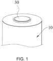
FIG. 1 is a schematic view illustrating a structure of a battery according to an exemplary embodiment. -
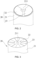
FIG. 2 is a schematic view illustrating a structure of a winding cell of the battery according to an exemplary embodiment. -
FIG. 3 is a schematic view illustrating the structure of the winding cell of the battery according to another exemplary embodiment. -
FIG. 4 is a cross-sectional schematic view illustrating the structure of the winding cell of the battery according to an exemplary embodiment. -
FIG. 5 is a schematic view illustrating part of a structure of stacked units of the battery according to an exemplary embodiment. -
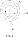
FIG. 6 is a cross-sectional schematic view illustrating a winding structure of the stacked units of the battery according to an exemplary embodiment, -
FIG. 7 is a cross-sectional schematic view illustrating the winding structure of the stacked units of the battery according to another exemplary embodiment. - The technical solutions in the exemplary embodiments of the disclosure will be described clearly and explicitly in conjunction with the drawings in the exemplary embodiments of the disclosure. The description proposed herein is just the exemplary embodiments for the purpose of illustrations only, not intended to limit the scope of the disclosure, so it should be understood that and various modifications and variations could be made thereto without departing from the scope of the disclosure.
- In the description of the present disclosure, unless otherwise specifically defined and limited, the terms "first", "second" and the like are only used for illustrative purposes and are not to be construed as expressing or implying a relative importance. The term "plurality" is two or more. The term "and/or" includes any and all combinations of one or more of the associated listed items.
- In particular, a reference to "the" object or "a" and "an" object is intended to denote also one of a possible plurality of such objects. Unless otherwise defined or described, the terms "connect", "fix" should be broadly interpreted, for example, the term "connect" can be "fixedly connect", "detachably connect", "integrally connect", "electrically connect" or "signal connect". The term "connect" also can be "directly connect" or "indirectly connect via a medium". For the persons skilled in the art, the specific meanings of the abovementioned terms in the present disclosure can be understood according to the specific situation.
- Further, in the description of the present disclosure, it should be understood that spatially relative terms, such as "above", "below" "inside", "outside" and the like, are described based on orientations illustrated in the figures, but are not intended to limit the exemplary embodiments of the present disclosure.
- In the context, it should also be understood that when an element or features is provided "outside" or "inside" of another element(s), it can be directly provided "outside" or "inside" of the other element, or be indirectly provided "outside" or "inside" of the another element(s) by an intermediate element.
- An embodiment of the disclosure provides a cylindrical battery. With reference to
FIG. 1 to FIG. 5 , the cylindrical battery includes abattery casing 10 and awinding cell 20. Thewinding cell 20 is disposed in thebattery casing 10 and includes acell body 21 and afirst tab portion 22. Thefirst tab portion 22 extends from one side of thecell body 21, and thecell body 21 is formed with awinding cell hole 211. Herein, in a radial direction of thewinding cell hole 211, thefirst tab portion 22 is formed by a plurality of first tabs gathered and connected together. The first tab among the plurality of first tabs closest to thewinding cell hole 211 is a 1stfirst tab 221. A distance between the 1stfirst tab 221 and thewinding cell hole 211 is not less than a length of the 1stfirst tab 221 in a lead-out direction thereof. - The cylindrical battery provided by an embodiment of the disclosure includes the
battery casing 10 and thewinding cell 20. Thewinding cell 20 is disposed in thebattery casing 10 and includes thecell body 21 and thefirst tab portion 22. Thefirst tab portion 22 extends from one side of thecell body 21, and thecell body 21 is formed with thewinding cell hole 211. Thefirst tab portion 22 may be formed by a plurality of first tabs. By making the distance between the 1stfirst tab 221 and thewinding cell hole 211 not less than the length of the 1stfirst tab 221 in the lead-out direction thereof, the 1stfirst tab 221 is prevented from extending and blocking thewinding cell hole 211 after being bundled, and the electrolyte infiltration rate of thewinding cell 20 is also prevented from being affected. Further, the safety risk caused by wrong lapping with tabs or electrode pieces of different polarities is also prevented, and the safety performance of the cylindrical battery is thus improved. - It should be noted that the cylindrical battery is a wound battery, and the winding
cell 20 may be wound on a windingcell rod body 216. In this way, after thewinding cell 20 is formed by winding, the windingcell rod body 216 is separated from thewinding cell 20, and thewinding cell hole 211 is formed. Thefirst tab portion 22 on thebattery cell body 21 is not present at the initial stage of winding, but only be presented after a certain number of turns of winding. In this way, it is ensured that the distance between the 1stfirst tab 221 and thewinding cell hole 211 is greater than or equal to the length of the 1stfirst tab 221 in the lead-out direction thereof, and short-circuit connection with other structures after the 1stfirst tab 221 is bundled is thus prevented from occurring. - The
cell body 21 may include a first electrode piece, and thefirst tab portion 22 may extend from one end of the first electrode piece. Therefore, after the first electrode piece is wound, thefirst tab portion 22 is formed on the first electrode piece. In the radial direction of thewinding cell hole 211, thefirst tab portion 22 may be formed by multiple layers of first tabs, and each layer of first tabs may include one or more first tabs. In this embodiment, in the radial direction of thewinding cell hole 211, thefirst tab portion 22 includes a plurality of first tabs. That is, the key point is to determine the 1stfirst tab 221, without considering how many first tabs there are in each layer of first tabs. The radial direction of thewinding cell hole 211 is a direction extending from the center point of thewinding cell hole 211 to the peripheral outer edge of thewinding cell hole 211. Therefore, there are multiple radial directions of thewinding cell hole 211. It is herein to illustrate that in one radial direction of thewinding cell hole 211, thefirst tab portion 22 includes a plurality of first tabs. - The first tabs on the first electrode piece may be a whole. That is, after the first electrode piece is wound, the
first tab portion 22 formed by the first tabs as a whole is in the shape of a ring. Herein, the first tabs of the first tabs of each layer are connected. Alternatively, the first tabs on the first electrode piece may be independently arranged. Therefore, after the first electrode piece is wound, thefirst tab portion 22 formed by the plurality of independently arranged first tabs forms a circumferential non-closed structure. - The first tabs on the first electrode piece are in a fluffy state after being wound. Therefore, each first tab may be bundled so as to ensure that the first tabs may form reliable contact, and the current-passing capability of the
first tab portion 22 is thus ensured. - Regarding the length of the 1st
first tab 221 in the lead-out direction thereof, the 1stfirst tab 221 extends from one side of thecell body 21. The lead-out direction of the 1stfirst tab 221 may be treated as an extending direction of the 1stfirst tab 221 after the 1stfirst tab 221 is straightened. That is, the extending direction of the 1stfirst tab 221 is parallel to an axial direction of the windingcell hole 211. After the 1stfirst tab 221 is straightened, the length dimension of the 1stfirst tab 221 in the axial direction of the windingcell hole 211 is the length of the 1stfirst tab 221 in the lead-out direction thereof. - The distance between the 1st
first tab 221 and the windingcell hole 211 is a distance between a bottom end of the 1stfirst tab 221 connected to thecell body 21 and a hole wall of the windingcell hole 211. Therefore, only when the distance between the 1stfirst tab 221 and the windingcell hole 211 is ensured to be greater than or equal to the length of the 1stfirst tab 221 in the lead-out direction thereof can it be ensured that the 1stfirst tab 221 may not block the windingcell hole 211 after being bundled. - In an embodiment, the distance between the 1st
first tab 221 and the windingcell hole 211 is 3 mm to 10 mm. On the basis of ensuring a reliable distance between the 1stfirst tab 221 and the hole wall of the windingcell hole 211, the problem of the small length dimension of thefirst tab portion 22 in the radial direction of the windingcell hole 211 may also be prevented from occurring. Therefore, it is ensured that thefirst tab portion 22 may have a reliable current-passing capability, and the safe use performance of the cylindrical battery is thus improved. - The distance between the 1st
first tab 221 and the windingcell hole 211 may be 3 mm, 3.1 mm, 3.2 mm, 3.5 mm, 3.8 mm, 4 mm, 4.5 mm, 5 mm, 5.5 mm, 6 mm, 7 mm, 7.5 mm, 8 mm, 8.5 mm, 9 mm, 9.3 mm, 9.5 mm, 9.6 mm, 9.8 mm, 9.9 mm, or 10 mm, etc. - When the distance between the 1st
first tab 221 and the windingcell hole 211 is less than 3 mm, the distance between thefirst tab portion 22 and the windingcell hole 211 may be too small. Further, the current-passing area of thefirst tab portion 22 may be insufficient, thefirst tab portion 22 may be difficult to be welded, and the risk of insulation failure may occur. When the distance between the 1stfirst tab 221 and the windingcell hole 211 is greater than 10mm, the distance between thefirst tab portion 22 and the windingcell hole 211 may be too large. Since the front end of thecell body 21 does not lead out thefirst tab portion 22, the electron transmission rate of the whole windingcell 20 is thus affected. - In an embodiment, the length of the 1st
first tab 221 in the lead-out direction thereof may be 3 mm to 10 mm. On the basis of ensuring that the 1stfirst tab 221 may not block the windingcell hole 211 after being bundled, the 1stfirst tab 221 may have a reasonable length, so as to ensure the current-passing capability of thefirst tab portion 22. - The length of the 1st
first tab 221 in the lead-out direction thereof may be 3 mm, 3.1 mm, 3.2 mm, 3.5 mm, 3.8 mm, 4 mm, 4.5 mm, 5 mm, 5.5 mm, 6 mm, 7 mm, 7.5 mm, 8 mm, 8.5 mm, 9 mm, 9.3 mm, 9.5 mm, 9.6 mm, 9.8 mm, 9.9 mm, or 10 mm, etc. - In an embodiment, as shown in
FIG. 2 to FIG. 4 , the windingcell 20 further includes asecond tab portion 23, and thefirst tab portion 22 and thesecond tab portion 23 have opposite polarities. Thefirst tab portion 22 and thesecond tab portion 23 extend from a same side of thecell body 21, and thefirst tab portion 22 is spaced apart from thesecond tab portion 23. In this way, the insulation between thefirst tab portion 22 and thesecond tab portion 23 is ensured, and short circuit problems are prevented from occurring. - The
first tab portion 22 and thesecond tab portion 23 have opposite polarities. One of thefirst tab portion 22 and thesecond tab portion 23 is a positive tab, and the other is a negative tab. By arranging thefirst tab portion 22 and thesecond tab portion 23 to extend from the same side of thecell body 21, the problem of excessive accumulation of height space caused by the extension of thefirst tab portion 22 and thesecond tab portion 23 from opposite sides of thecell body 21 may be prevented from occurring. - In an embodiment, the
first tab portion 22 is spaced apart from thesecond tab portion 23 in a circumferential direction of the windingcell hole 211. That is, thefirst tab portion 22 is spaced apart from and is arranged around thesecond tab portion 23 in the circumferential direction of the windingcell hole 211. In this way, the connection area between thefirst tab portion 22 and thesecond tab portion 23 is increased to the greatest extent, and it is also ensured that thefirst tab portion 22 and thesecond tab portion 23 may have a reliable current-passing area. - In an embodiment, the
second tab portion 23 is formed by a plurality of second tabs gathered and connected together. The second tab among the plurality of second tabs closest to the windingcell hole 211 is a 1stsecond tab 231. A distance between the 1stsecond tab 231 and the windingcell hole 211 is not less than a length of the 1stsecond tab 231 in a lead-out direction thereof. In this way, the secondfirst tab 231 is prevented from extending and blocking the windingcell hole 211 after being bundled, the safety risk caused by wrong lapping with thefirst tab portion 22 of different polarities is also prevented, and the safety performance of the cylindrical battery is thus improved. - The
first tab portion 22 is spaced apart from thesecond tab portion 23 in the circumferential direction of the windingcell hole 211. Further, the distance between the 1stfirst tab 221 and the windingcell hole 211 is not less than the length of the 1stfirst tab 221 in the lead-out direction thereof. The distance between the 1stsecond tab 231 and the windingcell hole 211 is not less than the length of the 1stsecond tab 231 in the lead-out direction thereof. Therefore, the 1stfirst tab 221 and the 1stsecond tab 231 are prevented from extending and blocking the windingcell hole 211 after being bundled. Further, the possibility of false contact between the 1stfirst tab 221 and the 1stsecond tab 231 may also be prevented from occurring to the greatest extent. - With reference to
FIG. 2 to FIG. 4 together, thefirst tab portion 22 is spaced apart from thesecond tab portion 23 in the circumferential direction of the windingcell hole 211. The 1stfirst tab 221 and the 1stsecond tab 231 may be arranged to be opposite to each other. The 1stfirst tab 221 and the 1stsecond tab 231 may also be arranged to be adjacent to each other. The specific positional relationship between the 1stfirst tab 221 and the 1stsecond tab 231 is not limited. - In an embodiment, the distance between the 1st
first tab 221 and the windingcell hole 211 is basically equal to the distance between the 1stsecond tab 231 and the windingcell hole 211. In this way, in the process of forming thefirst tab portion 22 and thesecond tab portion 23 by winding, the 1stfirst tab 221 and the 1stsecond tab 231 may be present in the same circle, so as to facilitate the winding of the windingcell 20. Further, the difficulty of designing the timing of the presence of the 1stfirst tab 221 and the 1stsecond tab 231 before winding to form the windingcell 20 is also lowered. - In an embodiment, the distance between the 1st
first tab 221 and the windingcell hole 211 is not equal to the distance between the 1stsecond tab 231 and the windingcell hole 211. That is, in the process of forming thefirst tab portion 22 and thesecond tab portion 23 by winding, the 1stfirst tab 221 and the 1stsecond tab 231 may not be present in the same circle. In this way, by controlling the distances between the 1stfirst tab 221 and the 1stsecond tab 231 and the windingcell hole 211, an insulation distance between the 1stfirst tab 221 and the 1stsecond tab 231 may be controlled to improve the safety performance of the battery. - In an embodiment, a radian of the 1st
first tab 221 is less than 2π, and a radian of the 1stsecond tab 231 is less than 2π. In this way, a reliable insulation distance is ensured between the 1stfirst tab 221 and the 1stsecond tab 231 to avoid battery safety issues. - The 1st
first tab 221 and the 1stsecond tab 231 may be on the same turn of the windingcell 20. Herein, a sum of the radians of the 1stfirst tab 221 and the 1stsecond tab 231 is less than 2π. - The 1st
first tab 221 and the 1stsecond tab 231 may be on different turns of the windingcell 20. Herein, the sum of the radians of the 1stfirst tab 221 and the 1stsecond tab 231 may be less than 2π. - In some embodiments, it is not excluded that the sum of the radians of the 1st
first tab 221 and the 1stsecond tab 231 may be greater than 2π. For instance, thefirst tab portion 22 may be a first ring-shaped structure located on thecell body 21 close to the windingcell hole 211, and thesecond tab portion 23 may be a second ring-shaped structure located on thecell body 21 away from the windingcell hole 211. Herein, the sum of the radians of the 1stfirst tab 221 and the 1stsecond tab 231 may be equal to 4π. - The
first tab portion 22 may be a first ring-shaped structure located on thecell body 21 close to the windingcell hole 211, and thesecond tab portion 23 may be a second ring-shaped structure located on thecell body 21 away from the windingcell hole 211. The distance between the 1stfirst tab 221 of thefirst tab portion 22 and the windingcell hole 211 is not less than the length of the 1stfirst tab 221 in the lead-out direction thereof. The distance between the 1stsecond tab 231 of thesecond tab portion 23 and thefirst tab portion 22 is not less than the length of the 1stsecond tab 231 in the lead-out direction thereof. In this way, the 1stsecond tab 231 is prevented from contacting thefirst tab portion 22 after being gathered in a direction close to the windingcell hole 211. - In an embodiment, as shown in
FIG. 2 , onefirst tab portion 22 is provided, and onesecond tab portion 23 is provided. In this way, a simple structure is provided, and on the basis of ensuring the insulation gap between thefirst tab portion 22 and thesecond tab portion 23, it can also be ensured that thefirst tab portion 22 and thesecond tab portion 23 have a reliable current-passing capability. - In an embodiment, a plurality of
first tab portions 22 are provided, and a plurality ofsecond tab portions 23 are provided. The plurality offirst tab portions 22 and the plurality ofsecond tab portions 23 may be arranged at intervals in the circumferential direction of the windingcell hole 211. On the basis of ensuring the insulation gaps between thefirst tab portions 22 and thesecond tab portions 23, it can also be ensured that thefirst tab portions 22 and thesecond tab portions 23 have sufficient current-passing areas. - With reference to
FIG. 3 , a plurality offirst tab portions 22 are provided, a plurality ofsecond tab portions 23 are provided, and thefirst tab portions 22 and thesecond tab portions 23 may be arranged in an alternating manner. - Alternatively, a plurality of
first tab portions 22 are provided, a plurality ofsecond tab portions 23 are provided, thefirst tab portions 22 may be arranged adjacently and sequentially, and thesecond tab portions 23 may be arranged adjacently and sequentially. - It should be noted that in some embodiments, it is not excluded that the
first tab portion 22 and thesecond tab portion 23 may extend from opposite sides of thecell body 21. In this case, both thefirst tab portion 22 and thesecond tab portion 23 may be ring-shaped. Certainly, it is not excluded that thefirst tab portion 22 and thesecond tab portion 23 may be non-closed structures in the circumferential direction. - In an embodiment, the battery includes a winding cell and an electrolyte, and the battery is the smallest unit capable of performing electrochemical reactions such as charging/discharging.
- The
cell body 21 includes a plurality of stacked units, and the plurality of stacked units are wound to form thecell body 21. The stacked units are connected in the circumferential direction of the windingcell hole 211 to form an integral structure. Thecell body 21 defined herein includes a plurality of stacked units, and each stacked unit forms a ring structure of thecell body 21. - With reference to
FIG. 5 , in the radial direction of the windingcell hole 211, the stacked units include afirst electrode piece 212, afirst separator 213, asecond electrode piece 214, and asecond separator 215 arranged in sequence. The stacked units may be wound on the windingcell rod body 216 to form the windingcell 20. For instance, thefirst electrode piece 212 may be located at the innermost layer of thecell body 21. Thefirst separator 213 and thesecond separator 215 effectively isolate thefirst electrode piece 212 and thesecond electrode piece 214. Lengths of thefirst separator 213 and thesecond separator 215 may be greater than the lengths of thefirst electrode piece 212 and thesecond electrode piece 214. Thefirst electrode piece 212 and thesecond electrode piece 214 have opposite polarities. One of thefirst electrode piece 212 and thesecond electrode piece 214 is a positive electrode piece, and the other is a negative electrode piece. - In an embodiment, wherein a distance between the nth first tab and a centerline of the winding cell hole 322 is rn = r1+a (ϕn-ϕ1), where n is a distance between the 1st
first tab 221 and the centerline of the windingcell hole 211, a=k/2n, k is a thickness of the stacked units, ϕn is an angle at which the nth first tab is wound from a winding starting point of the stacked units, and ϕ1 is an angle at which the 1stfirst tab 221 is wound from the winding starting point of the stacked units. By calculating ϕn-ϕ1, the bypassed angle of each stacked unit between the nth first tab and the 1stfirst tab 221 can be obtained, and the number of layers bypassed by the stacked units between the nth first tab and the 1stfirst tab 221 can be further determined. By obtaining the distance between the 1stfirst tab 221 and the centerline of the windingcell hole 211 and by calculating the distance between the 1stfirst tab 221 and the centerline of the windingcell hole 211 and the sum of the thicknesses of the stacked units between the nth first tab and the 1stfirst tab 221, the precise distance between the nth first tab and the centerline of the windingcell hole 211 can be obtained. - The angle of ϕn-ϕ1 is a natural multiple of 360°, and r1 is the distance between the 1st
first tab 221 and the centerline of the windingcell hole 211. The distance between the 1stfirst tab 221 and the centerline of the windingcell hole 211 is the smallest, and the side of the 1stfirst tab 221 facing the windingcell hole 211 is exposed. Therefore, the distance r1 between the 1stfirst tab 221 and the centerline of the windingcell hole 211 can be a distance value obtained by measurement, for example, when n=1, the angle ϕn-ϕ1 is 0, and rn= r1 herein. - In an embodiment, as shown in
FIG. 5 , the stacked units include thefirst electrode piece 212, thefirst separator 213, thesecond electrode piece 214, and thesecond separator 215 arranged in sequence. Thefirst separator 213 and thesecond separator 215 effectively isolate thefirst electrode piece 212 and thesecond electrode piece 214, so that the safety performance of the windingcell 20 is ensured, k is a sum of thicknesses of thefirst electrode piece 212, thefirst separator 213, thesecond electrode piece 214, and thesecond separator 215. - In some embodiments, it is not excluded that the stacked units may include the
first electrode piece 212 and thesecond electrode piece 214, and thefirst electrode piece 212 and thesecond electrode piece 214 may be in direct contact, k is the sum of the thicknesses of thefirst electrode piece 212 and thesecond electrode piece 214. - In an embodiment, the
first tab portion 22 extends from thefirst electrode piece 212. The distance between the 1stfirst tab 221 and the windingcell hole 211 is b, b=aϕ, ϕ=ϕ1-ϕ0, and ϕ0 is a winding angle from the winding starting point to a predetermined position point. In a winding direction of the stacked units, a connection line is formed between an end of the 1stfirst tab 221 close to the winding starting point and the centerline of the windingcell hole 211. The predetermined position point is an intersection point formed by the connection line and the stacked unit close to the windingcell hole 211, where 0≤ϕ0 < 360°. - With reference to
FIG. 6 andFIG. 7 together, the centerline of the windingcell hole 211 is denoted as A, the winding starting point is denoted as B, one end of the 1stfirst tab 221 close to the winding starting point is denoted as C, and the connection line between one end of the 1stfirst tab 221 close to the winding starting point and the centerline of the windingcell hole 211 is denoted as D. The intersection point formed by the connection line and the stacked unit close to the windingcell hole 211 is the predetermined position point E. The winding direction of the stacked unit may be indicated by the arrows shown inFIG. 6 andFIG. 7 . - As shown in
FIG. 6 , the winding starting point B may overlap the predetermined position point E. In this case, the winding angle from the winding starting point B to the predetermined position point E is 0, and the angle ϕ1 at which the 1stfirst tab 221 is wound from the winding starting point B of the stacked units may be a natural multiple of 360°. For instance, as shown inFIG. 6 , ϕ1 may be 3×360°. In this case, ϕ can be 3×360°, and a=k/2π, where k is the thickness of the stacked units, that is, the sum of the thicknesses of thefirst electrode piece 212, thefirst separator 213, thesecond electrode piece 214, and thesecond separator 215. Therefore, it can be obtained that the distance between the 1stfirst tab 221 and the windingcell hole 211 is b, where b=3k. - With reference to
FIG. 7 , the winding starting point B may not overlap the predetermined position point E. In this case, the winding angle from the winding starting point B to the predetermined position point E is ϕ0, and the angle ϕ1 at which the 1stfirst tab 221 is wound from the winding starting point B of the stacked units may be ϕ1, and ϕ1-ϕ0 is a natural multiple of 360°. For instance, as shown inFIG. 7 , ϕ can be 3×360°, and a=k/2π, where k is the thickness of the stacked units, that is, the sum of the thicknesses of thefirst electrode piece 212, thefirst separator 213, thesecond electrode piece 214, and thesecond separator 215. Therefore, it can be obtained that the distance between the 1stfirst tab 221 and the windingcell hole 211 is b, where b=3k. - In an embodiment, as shown in
FIG. 1 , the cylindrical battery further includes aterminal component 30, and theterminal component 30 may disposed on thebattery casing 10. The windingcell 20 may be electrically connected toterminal component 30. For instance, thefirst tab portion 22 of the windingcell 22 may be electrically connected toterminal component 30. Theterminal component 30 and thebattery casing 10 are insulated from each other. Further, thesecond tab portion 23 of the windingcell 20 may be electrically connected to thebattery casing 10. - The cylindrical battery may include two
terminal components 30, and thefirst tab portion 22 and thesecond tab portion 23 of the windingcell 20 may be electrically connected to the twoterminal components 30. - In an embodiment, the
battery casing 10 may include a cover plate and a casing member. Theterminal component 30 may be disposed on the cover plate, and the casing member may be formed with an accommodating space. In this way, after the cover plate is connected to the casing member, the windingcell 20 may be effectively protected. The cover plate and the casing member may be welded, or the cover plate and the casing member may be riveted. - An embodiment of the disclosure further provides a battery apparatus including the abovementioned cylindrical battery.
- The cylindrical battery of the battery apparatus provided by an embodiment of the disclosure includes the
battery casing 10 and the windingcell 20, and the windingcell 20 is disposed in thebattery casing 10. The windingcell 20 includes thecell body 21 and thefirst tab portion 22. Thefirst tab portion 22 extends from one side of thecell body 21, and thecell body 21 is formed with the windingcell hole 211. Thefirst tab portion 22 may be formed by a plurality of first tabs. By making the distance between the 1stfirst tab 221 and the windingcell hole 211 not less than the length of the 1stfirst tab 221 in the lead-out direction thereof, the 1stfirst tab 221 is prevented from extending and blocking the windingcell hole 211 after being bundled, and the electrolyte infiltration rate of the windingcell 20 is also prevented from being affected. Further, the safety risk caused by wrong lapping with tabs or electrode pieces of different polarities is also prevented, and the safety performance of the battery apparatus is thus improved. - In an embodiment, the battery apparatus is a battery module or a battery pack.
- The battery module includes a plurality of cylindrical batteries. The battery module may also include a bracket, and the batteries may be fixed on the bracket.
- The battery pack includes a plurality of cylindrical batteries and a box, and the box is configured to fix the cylindrical batteries.
- Note that the battery pack includes cylindrical batteries, there may be a plurality of cylindrical batteries, and the plurality of cylindrical batteries are arranged in the box. Herein, the cylindrical batteries may be mounted in the box after forming a battery module. Alternatively, the cylindrical batteries may be directly arranged in the box, that is, the cylindrical batteries are not required to be arranged into groups, and the box is used to fix the cylindrical batteries.
- Other embodiments of the disclosure will be apparent to those skilled in the art from consideration of the specification and practice of the disclosure disclosed herein. The disclosure is intended to cover any variations, uses or adaptations of the disclosure. These variations, uses, or adaptations follow the general principles of the disclosure and include common general knowledge or conventional technical means in the art that are not disclosed in the present disclosure.
Claims (11)
- A cylindrical battery, comprising:a battery casing (10); anda winding cell (20) disposed in the battery casing (10) and comprising a cell body (21) and a first tab portion (22), wherein the first tab portion (22) extends from one side of the cell body (21), and the cell body (21) is formed with a winding cell hole (211),wherein in a radial direction of the winding cell hole (211), the first tab portion (22) is formed by a plurality of first tabs gathered and connected together, the first tab among the plurality of first tabs closest to the winding cell hole (211) is a 1st first tab (221), and a distance between the 1st first tab (221) and the winding cell hole (211) is not less than a length of the 1st first tab (221) in a lead-out direction thereof.
- The cylindrical battery according to claim 1, wherein the distance between the 1st first tab (221) and the winding cell hole (211) is 3 mm to 10 mm.
- The cylindrical battery according to claim 1, wherein the winding cell (20) further comprises a second tab portion (23), the first tab portion (22) and the second tab portion (23) have opposite polarities, the first tab portion (22) and the second tab portion (23) extend from a same side of the cell body (21), and the first tab portion (22) is spaced apart from the second tab portion (23).
- The cylindrical battery according to claim 3, wherein the first tab portion (22) is spaced apart from the second tab portion (23) in a circumferential direction of the winding cell hole (211), the second tab portion (23) is formed by a plurality of second tabs gathered and connected together, the second tab among the plurality of second tabs closest to the winding cell hole (211) is a 1st second tab (231), and a distance between the 1st second tab (231) and the winding cell hole (211) is not less than a length of the 1st second tab (231) in a lead-out direction thereof.
- The cylindrical battery according to claim 4, wherein the distance between the 1st first tab (221) and the winding cell hole (211) is basically equal to the distance between the 1st second tab (231) and the winding cell hole (211).
- The cylindrical battery according to claim 4, wherein the distance between the 1st first tab (221) and the winding cell hole (211) is not equal to the distance between the 1st second tab (231) and the winding cell hole (211).
- The cylindrical battery according to claim 4, wherein a radian of the 1st first tab (221) is less than 2π, and a radian of the 1st second tab (231) is less than 2π.
- The cylindrical battery according to claim 3, wherein a plurality of first tab portions (22) are provided, a plurality of second tab portions (23) are provided, and the plurality of first tab portions (22) and the plurality of second tab portions (23) are arranged at intervals in the circumferential direction of the winding cell hole (211).
- The cylindrical battery according to claim 1, wherein the cell body (21) comprises a plurality of stacked units, and the plurality of stacked units are wound to form the cell body (21),
wherein a distance between the nth first tab and a centerline of the winding cell hole (211) is rn = rn=r1+ a ((pn-φ1), where r1 is a distance between the 1st first tab (221) and the centerline of the winding cell hole (211), a=k/2π, k is a thickness of the stacked units, ϕn is an angle at which the nth first tab is wound from a winding starting point of the stacked units, and ϕ1 is an angle at which the 1st first tab (221) is wound from the winding starting point of the stacked units. - The cylindrical battery according to claim 9, wherein the stacked units comprise a first electrode piece (212), a first separator (213), a second electrode piece (214), and a second separator (215) arranged in sequence, and k is a sum of thicknesses of the first electrode piece (212), the first separator (213), the second electrode piece (214), and the second separator (215).
- The cylindrical battery according to claim 10, wherein the first tab portion (22) extends from the first electrode piece (212), the distance between the 1st first tab (221) and the winding cell hole (211) is b, where b=acp and ϕ=ϕ1-ϕ0, ϕ0 is a winding angle from the winding starting point to a predetermined position point, in a winding direction of the stacked units, a connection line is formed between an end of the 1st first tab (221) close to the winding starting point and the centerline of the winding cell hole (211), and the predetermined position point is an intersection point formed by the connection line and the stacked unit close to the winding cell hole (211), where 0≤ϕ0 < 360°.
Applications Claiming Priority (1)
| Application Number | Priority Date | Filing Date | Title |
|---|---|---|---|
| CN202211258242.1A CN115483488A (en) | 2022-10-13 | 2022-10-13 | Cylindrical battery |
Publications (1)
| Publication Number | Publication Date |
|---|---|
| EP4354568A1 true EP4354568A1 (en) | 2024-04-17 |
Family
ID=84395764
Family Applications (1)
| Application Number | Title | Priority Date | Filing Date |
|---|---|---|---|
| EP23163928.7A Pending EP4354568A1 (en) | 2022-10-13 | 2023-03-24 | Cylindrical battery |
Country Status (2)
| Country | Link |
|---|---|
| EP (1) | EP4354568A1 (en) |
| CN (1) | CN115483488A (en) |
Families Citing this family (3)
| Publication number | Priority date | Publication date | Assignee | Title |
|---|---|---|---|---|
| CN116845498B (en) * | 2023-07-03 | 2025-02-25 | 蜂巢能源科技股份有限公司 | Battery pack and power battery |
| CN119812173B (en) * | 2024-08-29 | 2025-11-04 | 比亚迪股份有限公司 | Electrode sheets and their design methods, electrode cores, battery cells, battery modules and electrical equipment |
| CN118899505B (en) * | 2024-10-09 | 2024-12-17 | 中创新航科技集团股份有限公司 | Battery cell |
Citations (5)
| Publication number | Priority date | Publication date | Assignee | Title |
|---|---|---|---|---|
| US20200235370A1 (en) * | 2019-01-22 | 2020-07-23 | Contemporary Amperex Technology Co., Limited | Secondary battery and battery module |
| CN211376807U (en) * | 2019-11-28 | 2020-08-28 | 苏州安靠电源有限公司 | Battery pole piece, battery roll core and cylindrical battery |
| WO2022158861A2 (en) * | 2021-01-19 | 2022-07-28 | 주식회사 엘지에너지솔루션 | Battery and current collector applied thereto, and battery pack and vehicle including such battery |
| WO2022170496A1 (en) * | 2021-02-09 | 2022-08-18 | 宁德时代新能源科技股份有限公司 | Electrode assembly, battery cell, battery, apparatus, manufacturing method, and manufacturing apparatus |
| CN217444585U (en) * | 2022-03-07 | 2022-09-16 | 蔚来汽车科技(安徽)有限公司 | Cylindrical battery core and cylindrical battery |
Family Cites Families (5)
| Publication number | Priority date | Publication date | Assignee | Title |
|---|---|---|---|---|
| JP3910740B2 (en) * | 1997-11-10 | 2007-04-25 | 日本碍子株式会社 | Lithium secondary battery |
| CN114759317B (en) * | 2022-04-13 | 2024-09-03 | 广州小鹏汽车科技有限公司 | A pole ear structure, cylindrical battery cell and vehicle |
| CN114975859B (en) * | 2022-06-20 | 2024-08-09 | 肇庆小鹏汽车有限公司 | Electrode plate, winding core and battery of battery |
| CN115117286B (en) * | 2022-06-20 | 2025-10-24 | 肇庆小鹏汽车有限公司 | Battery electrode sheet, winding core and battery |
| CN218334020U (en) * | 2022-10-13 | 2023-01-17 | 中创新航科技股份有限公司 | Cylindrical battery |
-
2022
- 2022-10-13 CN CN202211258242.1A patent/CN115483488A/en active Pending
-
2023
- 2023-03-24 EP EP23163928.7A patent/EP4354568A1/en active Pending
Patent Citations (5)
| Publication number | Priority date | Publication date | Assignee | Title |
|---|---|---|---|---|
| US20200235370A1 (en) * | 2019-01-22 | 2020-07-23 | Contemporary Amperex Technology Co., Limited | Secondary battery and battery module |
| CN211376807U (en) * | 2019-11-28 | 2020-08-28 | 苏州安靠电源有限公司 | Battery pole piece, battery roll core and cylindrical battery |
| WO2022158861A2 (en) * | 2021-01-19 | 2022-07-28 | 주식회사 엘지에너지솔루션 | Battery and current collector applied thereto, and battery pack and vehicle including such battery |
| WO2022170496A1 (en) * | 2021-02-09 | 2022-08-18 | 宁德时代新能源科技股份有限公司 | Electrode assembly, battery cell, battery, apparatus, manufacturing method, and manufacturing apparatus |
| CN217444585U (en) * | 2022-03-07 | 2022-09-16 | 蔚来汽车科技(安徽)有限公司 | Cylindrical battery core and cylindrical battery |
Also Published As
| Publication number | Publication date |
|---|---|
| CN115483488A (en) | 2022-12-16 |
Similar Documents
| Publication | Publication Date | Title |
|---|---|---|
| EP4354568A1 (en) | Cylindrical battery | |
| EP3051610B1 (en) | Electrode assembly and rechargeable battery having electrode tab | |
| EP4354569A1 (en) | Cylindrical battery | |
| US20110129707A1 (en) | Secondary battery | |
| KR20200039214A (en) | Rechargeable battery | |
| EP3731297B1 (en) | Battery module | |
| CN116670924A (en) | Electrode assembly and secondary battery including the same | |
| EP4354639A1 (en) | Cylindrical battery | |
| CN111033811A (en) | Battery laminate | |
| KR20160092872A (en) | Electrode assembly and rechargeable battery having electrode ta1p | |
| US20140038032A1 (en) | Rechargeable battery | |
| US20250246694A1 (en) | Secondary battery and battery pack including the same | |
| RU2669378C1 (en) | Multi-stage battery | |
| CN218334020U (en) | Cylindrical battery | |
| CN220272707U (en) | Battery and battery pack | |
| CN218448162U (en) | Cylindrical battery | |
| CN110380108B (en) | Cell and electrochemical device having the same | |
| KR20240170391A (en) | Power storage cell | |
| EP4354640A1 (en) | Cylindrical battery | |
| CN115911774A (en) | Battery monomer and consumer | |
| WO2023155125A1 (en) | Tab test method and apparatus | |
| CN118511370A (en) | Insulating part of electrodeless ear coiled core battery unit | |
| CN115472970B (en) | Cylindrical battery | |
| EP4468510A1 (en) | Electrode assembly structure, and cylindrical battery, battery pack and vehicle comprising same | |
| US20240128606A1 (en) | Cylindrical battery |
Legal Events
| Date | Code | Title | Description |
|---|---|---|---|
| PUAI | Public reference made under article 153(3) epc to a published international application that has entered the european phase |
Free format text: ORIGINAL CODE: 0009012 |
|
| STAA | Information on the status of an ep patent application or granted ep patent |
Free format text: STATUS: REQUEST FOR EXAMINATION WAS MADE |
|
| 17P | Request for examination filed |
Effective date: 20230324 |
|
| AK | Designated contracting states |
Kind code of ref document: A1 Designated state(s): AL AT BE BG CH CY CZ DE DK EE ES FI FR GB GR HR HU IE IS IT LI LT LU LV MC ME MK MT NL NO PL PT RO RS SE SI SK SM TR |