EP4354560A1 - Fuel cell membrane humidifier - Google Patents
Fuel cell membrane humidifier Download PDFInfo
- Publication number
- EP4354560A1 EP4354560A1 EP22864853.1A EP22864853A EP4354560A1 EP 4354560 A1 EP4354560 A1 EP 4354560A1 EP 22864853 A EP22864853 A EP 22864853A EP 4354560 A1 EP4354560 A1 EP 4354560A1
- Authority
- EP
- European Patent Office
- Prior art keywords
- fluid
- fuel cell
- cell membrane
- membrane humidifier
- bypass hole
- Prior art date
- Legal status (The legal status is an assumption and is not a legal conclusion. Google has not performed a legal analysis and makes no representation as to the accuracy of the status listed.)
- Pending
Links
- 239000000446 fuel Substances 0.000 title claims abstract description 65
- 210000000170 cell membrane Anatomy 0.000 title claims abstract description 44
- 239000012530 fluid Substances 0.000 claims abstract description 116
- 239000012528 membrane Substances 0.000 claims abstract description 45
- 239000012510 hollow fiber Substances 0.000 claims abstract description 28
- 238000005192 partition Methods 0.000 claims description 18
- 230000007423 decrease Effects 0.000 claims description 6
- 230000009977 dual effect Effects 0.000 claims description 5
- 239000000463 material Substances 0.000 claims description 4
- 238000000638 solvent extraction Methods 0.000 claims description 2
- 210000004027 cell Anatomy 0.000 description 21
- 229920005989 resin Polymers 0.000 description 8
- 239000011347 resin Substances 0.000 description 8
- 238000000034 method Methods 0.000 description 7
- 238000004382 potting Methods 0.000 description 7
- 239000005518 polymer electrolyte Substances 0.000 description 6
- 239000007789 gas Substances 0.000 description 5
- UFHFLCQGNIYNRP-UHFFFAOYSA-N Hydrogen Chemical compound [H][H] UFHFLCQGNIYNRP-UHFFFAOYSA-N 0.000 description 3
- QVGXLLKOCUKJST-UHFFFAOYSA-N atomic oxygen Chemical compound [O] QVGXLLKOCUKJST-UHFFFAOYSA-N 0.000 description 3
- 239000001257 hydrogen Substances 0.000 description 3
- 229910052739 hydrogen Inorganic materials 0.000 description 3
- 239000001301 oxygen Substances 0.000 description 3
- 229910052760 oxygen Inorganic materials 0.000 description 3
- XLYOFNOQVPJJNP-UHFFFAOYSA-N water Substances O XLYOFNOQVPJJNP-UHFFFAOYSA-N 0.000 description 3
- 239000002033 PVDF binder Substances 0.000 description 2
- NBIIXXVUZAFLBC-UHFFFAOYSA-N Phosphoric acid Chemical compound OP(O)(O)=O NBIIXXVUZAFLBC-UHFFFAOYSA-N 0.000 description 2
- 239000004952 Polyamide Substances 0.000 description 2
- 239000004954 Polyphthalamide Substances 0.000 description 2
- 239000004743 Polypropylene Substances 0.000 description 2
- 230000008859 change Effects 0.000 description 2
- 238000004891 communication Methods 0.000 description 2
- 238000010586 diagram Methods 0.000 description 2
- 230000000694 effects Effects 0.000 description 2
- 230000005611 electricity Effects 0.000 description 2
- 239000003792 electrolyte Substances 0.000 description 2
- 239000007788 liquid Substances 0.000 description 2
- 238000004519 manufacturing process Methods 0.000 description 2
- 230000000149 penetrating effect Effects 0.000 description 2
- 239000004033 plastic Substances 0.000 description 2
- 229920003023 plastic Polymers 0.000 description 2
- 229920002492 poly(sulfone) Polymers 0.000 description 2
- 229920002239 polyacrylonitrile Polymers 0.000 description 2
- 229920002647 polyamide Polymers 0.000 description 2
- 229920006375 polyphtalamide Polymers 0.000 description 2
- 229920001155 polypropylene Polymers 0.000 description 2
- 229920002981 polyvinylidene fluoride Polymers 0.000 description 2
- 238000010248 power generation Methods 0.000 description 2
- 239000000126 substance Substances 0.000 description 2
- BVKZGUZCCUSVTD-UHFFFAOYSA-L Carbonate Chemical compound [O-]C([O-])=O BVKZGUZCCUSVTD-UHFFFAOYSA-L 0.000 description 1
- 239000004962 Polyamide-imide Substances 0.000 description 1
- 239000004695 Polyether sulfone Substances 0.000 description 1
- 230000002159 abnormal effect Effects 0.000 description 1
- 230000005856 abnormality Effects 0.000 description 1
- 230000002411 adverse Effects 0.000 description 1
- 230000004075 alteration Effects 0.000 description 1
- 229910000147 aluminium phosphate Inorganic materials 0.000 description 1
- 230000008901 benefit Effects 0.000 description 1
- 238000005266 casting Methods 0.000 description 1
- 239000003054 catalyst Substances 0.000 description 1
- 238000006243 chemical reaction Methods 0.000 description 1
- 238000002485 combustion reaction Methods 0.000 description 1
- 230000003247 decreasing effect Effects 0.000 description 1
- 239000013013 elastic material Substances 0.000 description 1
- 229920001971 elastomer Polymers 0.000 description 1
- 238000005265 energy consumption Methods 0.000 description 1
- 239000003344 environmental pollutant Substances 0.000 description 1
- 238000002347 injection Methods 0.000 description 1
- 239000007924 injection Substances 0.000 description 1
- 238000003780 insertion Methods 0.000 description 1
- 230000037431 insertion Effects 0.000 description 1
- 230000010354 integration Effects 0.000 description 1
- 239000002184 metal Substances 0.000 description 1
- 239000000203 mixture Substances 0.000 description 1
- 238000012986 modification Methods 0.000 description 1
- 230000004048 modification Effects 0.000 description 1
- 231100000719 pollutant Toxicity 0.000 description 1
- 229920003055 poly(ester-imide) Polymers 0.000 description 1
- 229920002312 polyamide-imide Polymers 0.000 description 1
- 229920000515 polycarbonate Polymers 0.000 description 1
- 239000004417 polycarbonate Substances 0.000 description 1
- 229920006393 polyether sulfone Polymers 0.000 description 1
- 229920001721 polyimide Polymers 0.000 description 1
- 239000009719 polyimide resin Substances 0.000 description 1
- 229920000642 polymer Polymers 0.000 description 1
- 229920006254 polymer film Polymers 0.000 description 1
- -1 polypropylene Polymers 0.000 description 1
- 229920005749 polyurethane resin Polymers 0.000 description 1
- 230000036647 reaction Effects 0.000 description 1
- 238000000926 separation method Methods 0.000 description 1
- 239000007787 solid Substances 0.000 description 1
- 239000000243 solution Substances 0.000 description 1
- 238000003860 storage Methods 0.000 description 1
Images


Classifications
-
- H—ELECTRICITY
- H01—ELECTRIC ELEMENTS
- H01M—PROCESSES OR MEANS, e.g. BATTERIES, FOR THE DIRECT CONVERSION OF CHEMICAL ENERGY INTO ELECTRICAL ENERGY
- H01M8/00—Fuel cells; Manufacture thereof
- H01M8/04—Auxiliary arrangements, e.g. for control of pressure or for circulation of fluids
- H01M8/04082—Arrangements for control of reactant parameters, e.g. pressure or concentration
- H01M8/04089—Arrangements for control of reactant parameters, e.g. pressure or concentration of gaseous reactants
- H01M8/04119—Arrangements for control of reactant parameters, e.g. pressure or concentration of gaseous reactants with simultaneous supply or evacuation of electrolyte; Humidifying or dehumidifying
- H01M8/04126—Humidifying
- H01M8/04149—Humidifying by diffusion, e.g. making use of membranes
-
- B—PERFORMING OPERATIONS; TRANSPORTING
- B01—PHYSICAL OR CHEMICAL PROCESSES OR APPARATUS IN GENERAL
- B01D—SEPARATION
- B01D63/00—Apparatus in general for separation processes using semi-permeable membranes
- B01D63/02—Hollow fibre modules
- B01D63/04—Hollow fibre modules comprising multiple hollow fibre assemblies
-
- H—ELECTRICITY
- H01—ELECTRIC ELEMENTS
- H01M—PROCESSES OR MEANS, e.g. BATTERIES, FOR THE DIRECT CONVERSION OF CHEMICAL ENERGY INTO ELECTRICAL ENERGY
- H01M8/00—Fuel cells; Manufacture thereof
- H01M8/04—Auxiliary arrangements, e.g. for control of pressure or for circulation of fluids
- H01M8/04082—Arrangements for control of reactant parameters, e.g. pressure or concentration
- H01M8/04089—Arrangements for control of reactant parameters, e.g. pressure or concentration of gaseous reactants
- H01M8/04119—Arrangements for control of reactant parameters, e.g. pressure or concentration of gaseous reactants with simultaneous supply or evacuation of electrolyte; Humidifying or dehumidifying
- H01M8/04126—Humidifying
- H01M8/04141—Humidifying by water containing exhaust gases
-
- B—PERFORMING OPERATIONS; TRANSPORTING
- B01—PHYSICAL OR CHEMICAL PROCESSES OR APPARATUS IN GENERAL
- B01D—SEPARATION
- B01D2313/00—Details relating to membrane modules or apparatus
- B01D2313/08—Flow guidance means within the module or the apparatus
- B01D2313/083—Bypass routes
-
- B—PERFORMING OPERATIONS; TRANSPORTING
- B01—PHYSICAL OR CHEMICAL PROCESSES OR APPARATUS IN GENERAL
- B01D—SEPARATION
- B01D2313/00—Details relating to membrane modules or apparatus
- B01D2313/18—Specific valves
-
- B—PERFORMING OPERATIONS; TRANSPORTING
- B01—PHYSICAL OR CHEMICAL PROCESSES OR APPARATUS IN GENERAL
- B01D—SEPARATION
- B01D2313/00—Details relating to membrane modules or apparatus
- B01D2313/44—Cartridge types
-
- H—ELECTRICITY
- H01—ELECTRIC ELEMENTS
- H01M—PROCESSES OR MEANS, e.g. BATTERIES, FOR THE DIRECT CONVERSION OF CHEMICAL ENERGY INTO ELECTRICAL ENERGY
- H01M8/00—Fuel cells; Manufacture thereof
- H01M8/10—Fuel cells with solid electrolytes
- H01M2008/1095—Fuel cells with polymeric electrolytes
-
- Y—GENERAL TAGGING OF NEW TECHNOLOGICAL DEVELOPMENTS; GENERAL TAGGING OF CROSS-SECTIONAL TECHNOLOGIES SPANNING OVER SEVERAL SECTIONS OF THE IPC; TECHNICAL SUBJECTS COVERED BY FORMER USPC CROSS-REFERENCE ART COLLECTIONS [XRACs] AND DIGESTS
- Y02—TECHNOLOGIES OR APPLICATIONS FOR MITIGATION OR ADAPTATION AGAINST CLIMATE CHANGE
- Y02E—REDUCTION OF GREENHOUSE GAS [GHG] EMISSIONS, RELATED TO ENERGY GENERATION, TRANSMISSION OR DISTRIBUTION
- Y02E60/00—Enabling technologies; Technologies with a potential or indirect contribution to GHG emissions mitigation
- Y02E60/30—Hydrogen technology
- Y02E60/50—Fuel cells
Definitions
- the present disclosure relates to a fuel cell membrane humidifier, and more particularly, to a fuel cell membrane humidifier which may improve the humidification efficiency by preventing a differential pressure loss in a humidification module.
- a fuel cell is a power-generating battery that produces electricity according to a combination of hydrogen with oxygen. Unlike general chemical cells such as batteries or storage batteries, fuel cells can continuously produce electricity as long as hydrogen and oxygen are supplied thereto, and are about twice as efficient as internal combustion engines because of no heat loss.
- pollutant emissions are low because the chemical energy generated by the combination of hydrogen with oxygen is directly converted into electrical energy. Accordingly, fuel cells are not only environmentally friendly, but also have the advantage of reducing concerns about resource depletion due to increased energy consumption.
- Fuel cells may be broadly classified into polymer electrolyte membrane fuel cells (PEMFC), phosphoric acid fuel cells (PAFC), molten carbonate fuel cells (MCFC), solid oxide fuel cells (SOFC), and alkaline fuel cells (AFC), depending on the type of electrolyte used.
- PEMFC polymer electrolyte membrane fuel cells
- PAFC phosphoric acid fuel cells
- MCFC molten carbonate fuel cells
- SOFC solid oxide fuel cells
- AFC alkaline fuel cells
- PEMFC proton exchange membranes
- Methods for humidifying the polymer electrolyte membranes include 1) a bubbler humidification method of supplying moisture by filling a pressure vessel with water and passing target gas through a diffuser, 2) a direct injection method of supplying moisture directly to a gas flow pipe through a solenoid valve after calculating the amount of moisture needed for the fuel cell reaction, and 3) a membrane humidification method of supplying moisture to the fluidized layer of gas using a polymer separation membrane.
- the membrane humidification method whereby a polymer electrolyte membrane is humidified by providing water vapor to air supplied to the polymer electrolyte membrane by using a membrane that selectively transmits only the water vapor contained in off-gas is advantageous in that the membrane humidifier can be lightened and miniaturized.
- hollow fiber membranes with a large permeable area per unit volume are preferable. That is, when manufacturing a membrane humidifier using hollow fiber membranes, high integration of the hollow fiber membranes with a wide contact surface area is possible, which enables sufficient humidification of a fuel cell even with a small capacity, low-cost materials may be used, and moisture and heat contained in off-gas discharged at high temperature from the fuel cell may be recovered and reused through the membrane humidifier.
- the object of the present disclosure is to provide a fuel cell membrane humidifier which may improve the humidification efficiency by preventing a differential pressure loss in a humidification module.
- a fuel cell membrane humidifier performs moisture exchange between a first fluid and a second fluid and includes a mid-case, a second fluid inlet configured to introduce the second fluid into the mid-case, a second fluid outlet configured to discharge the second fluid to outside, and at least one cartridge arranged in the mid-case and accommodating a plurality of hollow fiber membranes.
- a cross-sectional area of the second fluid inlet is formed to be greater than or equal to an inner cross-sectional area of the at least one cartridge excluding a cross-sectional area occupied by the plurality of hollow fiber membranes accommodated in the at least one cartridge.
- an inner diameter of the second fluid inlet may be such that CS1 ⁇ CS2 - CS3.
- the fuel cell membrane humidifier may further include a partition wall partitioning an inner space of the mid-case into a first space and a second space, and an active bypass portion configured to adjust a flow rate of the second fluid flowing in the first space and the second space according to a flow rate of the second fluid introduced through the second fluid inlet.
- the active bypass portion may include a bypass hole formed by penetrating the partition wall, and a bypass hole opening/closing device configured to open/close the bypass hole according to a flow rate of the second fluid introduced through the second fluid inlet.
- the bypass hole opening/closing device may include a single valve member formed on the partition wall to cover the bypass hole.
- the bypass hole opening/closing device may include a dual valve member formed on the partition wall to cover the bypass hole from both sides.
- the bypass hole opening/closing device may include a double valve member formed on the partition wall to cover the bypass hole from both sides while at least partially overlapping each other.
- the bypass hole opening/closing device may include a flexible material having a shape that deforms when a pressure applied thereto increases and returns to an original shape when the pressure decreases.
- the humidification efficiency may be improved by preventing a differential pressure loss in a humidification module.
- FIG. 1 is a front view of a fuel cell membrane humidifier according to embodiments of the present disclosure.
- FIG. 2 is a plan view of a fuel cell membrane humidifier according to embodiments of the present disclosure.
- FIG. 3 is a cross-sectional view taken along line A-A' of FIG. 2 according to an embodiment.
- FIG. 4 is a side view of a humidification module with a cap removed from a fuel cell membrane humidifier according to an embodiment of FIG. 3 .
- FIG. 5 is a conceptual diagram showing a relationship among a cross-sectional area of a second fluid inlet, a cross-sectional area of a cartridge, and a total cross-sectional area of hollow fiber membranes.
- a fuel cell membrane humidifier according to an embodiment of the present disclosure includes a humidification module 110 and caps 120.
- the humidification module 110 performs moisture exchange between a first fluid supplied from the outside and a second fluid discharged from a fuel cell stack (not shown).
- the caps 120 are fastened to both ends of the humidification module 110. While a first fluid inlet 121 for supplying a first fluid supplied from the outside to the humidification module 110 is formed in one of the caps 120, a first fluid outlet 122 for supplying the first fluid humidified by the humidification module 110 to the fuel cell stack is formed in another of the caps 120.
- the humidification module 110 includes a mid-case 111 having a second fluid inlet 112 and a second fluid outlet 113, and at least one of a cartridge 20 arranged in the mid-case 111.
- the second fluid discharged from the fuel cell stack (not shown) is introduced through the second fluid inlet 112, performs moisture exchange in the humidification module 110, and then is discharged through the second fluid outlet 113.
- the fluid introduced/discharged through the second fluid inlet 112 or the second fluid outlet 113 is not limited to the second fluid. Furthermore, the fluid introduced/discharged through the first fluid inlet 121 or the first fluid outlet 122 is not limited to the first fluid.
- one of the caps 120 may be configured to supply the second fluid to the humidification module 110 to flow inside a hollow fiber membrane, and the one may be configured to discharge the second fluid having undergone the moisture-exchange to the outside.
- the first fluid may be introduced through one of the second fluid inlet 112 and the second fluid outlet 113, and the first fluid that has been humidified by the humidification module 110 may be supplied to the fuel cell stack through the other thereof.
- the flow direction of the first fluid and the flow direction of the second fluid may be the same or opposite to each other.
- the mid-case 111 and the caps 120 may be each independently formed of a hard plastic or metal, and may each have a circular or polygonal cross-section in a widthwise direction.
- the "circular” includes oval, and the "polygonal” includes a polygon with rounded corners.
- the hard plastic may be polycarbonate, polyamide (PA), polyphthalamide (PPA), polypropylene (PP), or the like.
- An internal space of the mid-case 111 may be partitioned into a first space S1 and a second space S2 by a partition wall 114.
- a flow of the second fluid introduced through the second fluid inlet 112 is blocked by the partition wall 114 so as not to be directly discharged through the second fluid outlet 113, but to flow through the cartridge 20 arranged in the mid-case 111 while performing moisture exchange, and then is discharged through the second fluid outlet 113.
- the partition wall 114 may be provided with an insertion hole H into which at least one cartridge 20 is inserted. The cartridge 20 is described below with reference with FIGS. 11 and 12 .
- the second fluid discharged from the fuel cell stack has a flow path of the second fluid inlet 112 --> the first space S1 --> the inner space of the cartridge 20 --> the second space S2 --> the second fluid outlet 113.
- the second fluid humidifies the first fluid.
- the cross-sectional area of the second fluid inlet 112 is designed considering the cross-sectional area of the cartridge 20 and the cross-sectional areas of the hollow fiber membranes 21 accommodated in the cartridge 20.
- the cross-sectional area of the second fluid inlet 112 may be formed to be greater than or equal to the inner cross-sectional area of the cartridge 20 excluding the cross-sectional area occupied by the hollow fiber membranes 21.
- the inner diameter of the second fluid inlet 112 may be such that CS1 ⁇ CS2 - CS3.
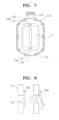
- FIG. 6 is a cross-sectional view taken along line A-A' of FIG. 2 according to another embodiment.
- FIG. 7 is a side view of a humidification module with a cap removed from a fuel cell membrane humidifier according to another embodiment of FIG. 6 .
- a fuel cell membrane humidifier according to another embodiment of the present disclosure includes the humidification module 110, the caps 120, and an active bypass portion 130.
- the humidification module 110 and the caps 120 are substantially the same as those of the embodiment described above, redundant descriptions thereof are omitted.
- the active bypass portion 130 adjusts a flow rate of the second fluid flowing in the first space S1 and the second space S2 according to a flow rate of the second fluid introduced through the second fluid inlet 112.
- the active bypass portion 130 includes a bypass hole 131 and a bypass hole opening/closing device 132.
- the bypass hole 131 is formed by penetrating the partition wall 114.
- the bypass hole 131 may be formed in various polygonal or circular shapes, such as a triangle, a rectangle, a circle, an oval, and the like.
- the bypass hole opening/closing device 132 is formed of a flexible material having a shape that deforms when a pressure applied thereto increases and returns to the original shape when the pressure decreases.
- the bypass hole opening/closing device 132 may be formed as an elastic valve formed of an elastic material (e.g., rubber).
- the bypass hole opening/closing device 132 formed as an elastic valve opens/closes the bypass hole 131 according to according to the flow rate of the second fluid introduced through the second fluid inlet 112.
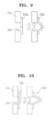
- FIGS. 8 to 10 illustrate active bypass portions according to various embodiments.
- the active bypass portion 130 may include the bypass hole 131 and a single valve member 132a formed on the partition wall 114 to cover the bypass hole 131.
- the single valve member 132a is formed only at one side of the vicinity of the bypass hole 131, it is advantageous that a manufacturing process is simple. It may be the most basic shape of the active bypass portion 130.
- the active bypass portion 130 may include the bypass hole 131 and a dual valve member 132b formed on the partition wall 114 to cover the bypass hole 131 from both sides.
- a change in the flow rate of the second fluid may be responded more sensitively.
- the dual valve member 132b may be more advantageous when the volume of the fuel cell membrane humidifier is less than a basic type.
- the active bypass portion 130 may include the bypass hole 131 and a double valve member 132c formed on the partition wall 114 to cover the bypass hole 131 from both sides while at least a portion of the members overlaps each other.
- the double valve member 132c is configured to at least partially overlap each other, a change in the flow rate of the second fluid may be responded more insensitively.
- the double valve member 132c may be more advantageous when the volume of the fuel cell membrane humidifier is greater than the basic type.
- a portion of the second fluid introduced through the second fluid inlet 112 flows from the first space S1 to the second space S2 through the active bypass portion 130 according to the flow rate of the second fluid and is discharged through the second fluid outlet 113.
- the second fluid introduced through the active bypass portion 130 is not in contact with the first fluid, moisture exchange is not performed.
- a differential pressure in the fuel cell membrane humidifier is abnormally increased by the second fluid introduced from the fuel cell stack.
- the differential pressure needs to be removed.
- the active bypass portion 130 allows a portion of the introduced second fluid to bypass the hollow fiber membranes according to the flow rate of the second fluid and to be discharged to the outside, an abnormal increase in differential pressure may be prevented.
- the fuel cell membrane humidifier including the active bypass portion 130 according to embodiments of the present disclosure is advantageous in the volume minimization.
- FIG. 11 is a side view of a cartridge installed on a fuel cell membrane humidifier according to embodiments of the present disclosure.
- FIG. 12 is a cross-sectional view of the cartridge installed on a fuel cell membrane humidifier according to embodiments of the present disclosure.
- the cartridge 20 includes the hollow fiber membranes 21, a potting portion 22, and an inner case 23.
- the hollow fiber membranes 21 may each include polysulfone resin, polyethersulfone resin, sulfonated polysulfone resin, polyvinylidene fluoride (PVDF) resin, polyacrylonitrile (PAN) resin, polyimide resin, polyamideimide resin, polyesterimide resin, or a polymer film formed of a mixture of at least two selected therefrom.
- PVDF polyvinylidene fluoride
- PAN polyacrylonitrile
- polyimide resin polyamideimide resin
- polyesterimide resin polyesterimide resin
- a polymer film formed of a mixture of at least two selected therefrom or a polymer film formed of a mixture of at least two selected therefrom.
- the potting portion 22 fixes ends of the hollow fiber membrane 21.
- the potting portion 22 may be formed by curing a liquid resin such as liquid polyurethane resin by a casting method such as deep potting or centrifugal potting.
- the inner case 23 has an opening at each end, and the hollow fiber membranes 21 are accommodated in the opening.
- the potting portion 22 in which the ends of the hollow fiber membranes 21 are potted closes the openings of the inner case 131.
- the inner case 23 includes a first mesh hole portion MH1 arranged in a mesh form for fluid communication with the first space S1, and a second mesh hole portion MH2 arranged in a mesh form for fluid communication with the second space S2.
- the second fluid introduced into the first space S1 of the mid-case 111 through the second fluid inlet 112 flows in the inner case 23 through the first mesh hole portion MH1 and then comes into contact with the outer surfaces of the hollow fiber membranes 21. Subsequently, the second fluid having undergone the moisture exchange exits to the second space S2 through the second mesh hole portion MH2 and is then discharged from the mid-case 111 through the second fluid outlet 113.
- the second fluid introduced into the second space S2 of the mid-case 111 through the second fluid outlet 113 flows in the inner case 23 through the second mesh hole portion MH2 and then comes into contact with the outer surfaces of the hollow fiber membranes 21. Subsequently, the second fluid having undergone the moisture exchange with the first fluid exits to the first space S1 through the first mesh hole portion MH1 and is then discharged from the mid-case 111 through the second fluid into 112.
- a gasket (not shown) may be provided between the mid-case 111 and the cartridge 20.
- the gasket mounts the cartridge 20 on the humidification module 110 through mechanical assembling. Accordingly, when an abnormality occurs in a specific portion (e.g., the cartridge 20) of the humidification module 110, the mid-case 111 and gasket 130 may be simply mechanically separated from the humidification module 110, and then, only the corresponding portion may be repaired or replaced.
Applications Claiming Priority (2)
| Application Number | Priority Date | Filing Date | Title |
|---|---|---|---|
| KR1020210115978A KR20230032781A (ko) | 2021-08-31 | 2021-08-31 | 연료전지 막가습기 |
| PCT/KR2022/009972 WO2023033344A1 (ko) | 2021-08-31 | 2022-07-08 | 연료전지 막가습기 |
Publications (1)
| Publication Number | Publication Date |
|---|---|
| EP4354560A1 true EP4354560A1 (en) | 2024-04-17 |
Family
ID=85411507
Family Applications (1)
| Application Number | Title | Priority Date | Filing Date |
|---|---|---|---|
| EP22864853.1A Pending EP4354560A1 (en) | 2021-08-31 | 2022-07-08 | Fuel cell membrane humidifier |
Country Status (4)
| Country | Link |
|---|---|
| EP (1) | EP4354560A1 (ko) |
| KR (1) | KR20230032781A (ko) |
| CN (1) | CN117795711A (ko) |
| WO (1) | WO2023033344A1 (ko) |
Family Cites Families (8)
| Publication number | Priority date | Publication date | Assignee | Title |
|---|---|---|---|---|
| KR20100125553A (ko) * | 2009-05-21 | 2010-12-01 | 현대자동차주식회사 | 연료전지용 막 가습기 |
| KR20110021217A (ko) | 2009-08-25 | 2011-03-04 | 코오롱인더스트리 주식회사 | 연료전지용 고분자 전해질막 및 그 제조방법 |
| KR20110026696A (ko) | 2009-09-08 | 2011-03-16 | 코오롱인더스트리 주식회사 | 연료전지용 가습기 및 그 제조방법 |
| WO2011068383A2 (en) | 2009-12-04 | 2011-06-09 | Kolon Industries, Inc. | Humidifier for fuel cell |
| KR101251256B1 (ko) * | 2011-03-09 | 2013-04-10 | 기아자동차주식회사 | 연료전지용 막 가습기 |
| KR101337904B1 (ko) * | 2011-09-14 | 2013-12-09 | 기아자동차주식회사 | 연료전지용 막 가습기 |
| KR101766011B1 (ko) * | 2015-04-30 | 2017-08-07 | 현대자동차주식회사 | 연료전지용 막가습기 |
| KR102204066B1 (ko) * | 2017-09-25 | 2021-01-15 | 코오롱인더스트리 주식회사 | 이종 재질의 중공사막을 구비한 중공사막 모듈 및 이를 포함하는 연료전지 막가습기 |
-
2021
- 2021-08-31 KR KR1020210115978A patent/KR20230032781A/ko unknown
-
2022
- 2022-07-08 WO PCT/KR2022/009972 patent/WO2023033344A1/ko active Application Filing
- 2022-07-08 EP EP22864853.1A patent/EP4354560A1/en active Pending
- 2022-07-08 CN CN202280053264.6A patent/CN117795711A/zh active Pending
Also Published As
| Publication number | Publication date |
|---|---|
| CN117795711A (zh) | 2024-03-29 |
| WO2023033344A1 (ko) | 2023-03-09 |
| KR20230032781A (ko) | 2023-03-07 |
Similar Documents
| Publication | Publication Date | Title |
|---|---|---|
| KR20190138288A (ko) | 연료전지 막가습기 | |
| US20240063408A1 (en) | Fuel cell membrane humidifier preventing damage of humidification membrane | |
| KR102471030B1 (ko) | 연료전지용 가습기 | |
| EP4354560A1 (en) | Fuel cell membrane humidifier | |
| EP4358201A1 (en) | Fuel cell membrane humidifier | |
| KR20220043352A (ko) | 연료전지용 가습기의 카트리지 및 연료전지용 가습기 | |
| EP4350820A1 (en) | Fuel cell membrane humidifier | |
| EP4358200A1 (en) | Cartridge for membrane humidifier, and fuel cell membrane humidifier comprising same | |
| US20240006633A1 (en) | Fuel cell membrane humidifier | |
| US20240097161A1 (en) | Fuel cell membrane humidifier and fuel cell system comprising same | |
| US20240021848A1 (en) | Cartridge of fuel cell humidifier, and fuel cell humidifier | |
| EP4318688A1 (en) | Fuel cell membrane humidifier | |
| US20240055626A1 (en) | Fuel cell membrane humidifier and fuel cell system comprising same | |
| EP4318689A1 (en) | Fuel cell membrane humidifier | |
| EP4318690A1 (en) | Fuel cell membrane humidifier | |
| US20230420706A1 (en) | Humidifier system for fuel cell | |
| KR102664877B1 (ko) | 연료전지 막가습기 | |
| US20240055625A1 (en) | Automatic flow rate control cartridge and fuel cell membrane humidifier comprising same | |
| CN216872049U (zh) | 燃料电池膜加湿器 | |
| EP4358199A1 (en) | Membrane humidifier cartridge and fuel cell membrane humidifier comprising same | |
| US20230378492A1 (en) | Fuel cell membrane humidifier and fuel cell system comprising same | |
| EP4258393A1 (en) | Cartridge of humidifier for fuel cell and humidifier for fuel cell | |
| KR20230032780A (ko) | 연료전지 막가습기 | |
| KR20230170221A (ko) | 연료전지용 가습기 및 연료전지용 가습기의 미드-케이스 | |
| KR20220089419A (ko) | 카트리지 및 이를 포함하는 연료전지 막가습기 |
Legal Events
| Date | Code | Title | Description |
|---|---|---|---|
| STAA | Information on the status of an ep patent application or granted ep patent |
Free format text: STATUS: THE INTERNATIONAL PUBLICATION HAS BEEN MADE |
|
| PUAI | Public reference made under article 153(3) epc to a published international application that has entered the european phase |
Free format text: ORIGINAL CODE: 0009012 |
|
| STAA | Information on the status of an ep patent application or granted ep patent |
Free format text: STATUS: REQUEST FOR EXAMINATION WAS MADE |
|
| 17P | Request for examination filed |
Effective date: 20240108 |
|
| AK | Designated contracting states |
Kind code of ref document: A1 Designated state(s): AL AT BE BG CH CY CZ DE DK EE ES FI FR GB GR HR HU IE IS IT LI LT LU LV MC MK MT NL NO PL PT RO RS SE SI SK SM TR |