EP4354368A1 - Electric-quantity-based path planning method for electric vehicle compatible with energy storage charging pile - Google Patents

Electric-quantity-based path planning method for electric vehicle compatible with energy storage charging pile Download PDF

Info

Publication number
EP4354368A1
EP4354368A1 EP22803901.2A EP22803901A EP4354368A1 EP 4354368 A1 EP4354368 A1 EP 4354368A1 EP 22803901 A EP22803901 A EP 22803901A EP 4354368 A1 EP4354368 A1 EP 4354368A1
Authority
EP
European Patent Office
Prior art keywords
charging
reserved
charging pile
electric vehicle
electric
Prior art date
Legal status (The legal status is an assumption and is not a legal conclusion. Google has not performed a legal analysis and makes no representation as to the accuracy of the status listed.)
Pending
Application number
EP22803901.2A
Other languages
German (de)
French (fr)
Other versions
EP4354368A4 (en
Inventor
Tao Wei
Current Assignee (The listed assignees may be inaccurate. Google has not performed a legal analysis and makes no representation or warranty as to the accuracy of the list.)
Individual
Original Assignee
Individual
Priority date (The priority date is an assumption and is not a legal conclusion. Google has not performed a legal analysis and makes no representation as to the accuracy of the date listed.)
Filing date
Publication date
Application filed by Individual filed Critical Individual
Publication of EP4354368A1 publication Critical patent/EP4354368A1/en
Publication of EP4354368A4 publication Critical patent/EP4354368A4/en
Pending legal-status Critical Current

Links

Images

Classifications

    • GPHYSICS
    • G06COMPUTING OR CALCULATING; COUNTING
    • G06QINFORMATION AND COMMUNICATION TECHNOLOGY [ICT] SPECIALLY ADAPTED FOR ADMINISTRATIVE, COMMERCIAL, FINANCIAL, MANAGERIAL OR SUPERVISORY PURPOSES; SYSTEMS OR METHODS SPECIALLY ADAPTED FOR ADMINISTRATIVE, COMMERCIAL, FINANCIAL, MANAGERIAL OR SUPERVISORY PURPOSES, NOT OTHERWISE PROVIDED FOR
    • G06Q10/00Administration; Management
    • G06Q10/04Forecasting or optimisation specially adapted for administrative or management purposes, e.g. linear programming or "cutting stock problem"
    • G06Q10/047Optimisation of routes or paths, e.g. travelling salesman problem
    • GPHYSICS
    • G01MEASURING; TESTING
    • G01CMEASURING DISTANCES, LEVELS OR BEARINGS; SURVEYING; NAVIGATION; GYROSCOPIC INSTRUMENTS; PHOTOGRAMMETRY OR VIDEOGRAMMETRY
    • G01C21/00Navigation; Navigational instruments not provided for in groups G01C1/00 - G01C19/00
    • G01C21/26Navigation; Navigational instruments not provided for in groups G01C1/00 - G01C19/00 specially adapted for navigation in a road network
    • G01C21/34Route searching; Route guidance
    • G01C21/3453Special cost functions, i.e. other than distance or default speed limit of road segments
    • G01C21/3469Fuel consumption; Energy use; Emission aspects
    • GPHYSICS
    • G06COMPUTING OR CALCULATING; COUNTING
    • G06QINFORMATION AND COMMUNICATION TECHNOLOGY [ICT] SPECIALLY ADAPTED FOR ADMINISTRATIVE, COMMERCIAL, FINANCIAL, MANAGERIAL OR SUPERVISORY PURPOSES; SYSTEMS OR METHODS SPECIALLY ADAPTED FOR ADMINISTRATIVE, COMMERCIAL, FINANCIAL, MANAGERIAL OR SUPERVISORY PURPOSES, NOT OTHERWISE PROVIDED FOR
    • G06Q10/00Administration; Management
    • G06Q10/02Reservations, e.g. for tickets, services or events
    • GPHYSICS
    • G06COMPUTING OR CALCULATING; COUNTING
    • G06QINFORMATION AND COMMUNICATION TECHNOLOGY [ICT] SPECIALLY ADAPTED FOR ADMINISTRATIVE, COMMERCIAL, FINANCIAL, MANAGERIAL OR SUPERVISORY PURPOSES; SYSTEMS OR METHODS SPECIALLY ADAPTED FOR ADMINISTRATIVE, COMMERCIAL, FINANCIAL, MANAGERIAL OR SUPERVISORY PURPOSES, NOT OTHERWISE PROVIDED FOR
    • G06Q10/00Administration; Management
    • G06Q10/06Resources, workflows, human or project management; Enterprise or organisation planning; Enterprise or organisation modelling
    • G06Q10/063Operations research, analysis or management
    • G06Q10/0631Resource planning, allocation, distributing or scheduling for enterprises or organisations
    • G06Q10/06312Adjustment or analysis of established resource schedule, e.g. resource or task levelling, or dynamic rescheduling
    • GPHYSICS
    • G06COMPUTING OR CALCULATING; COUNTING
    • G06QINFORMATION AND COMMUNICATION TECHNOLOGY [ICT] SPECIALLY ADAPTED FOR ADMINISTRATIVE, COMMERCIAL, FINANCIAL, MANAGERIAL OR SUPERVISORY PURPOSES; SYSTEMS OR METHODS SPECIALLY ADAPTED FOR ADMINISTRATIVE, COMMERCIAL, FINANCIAL, MANAGERIAL OR SUPERVISORY PURPOSES, NOT OTHERWISE PROVIDED FOR
    • G06Q50/00Information and communication technology [ICT] specially adapted for implementation of business processes of specific business sectors, e.g. utilities or tourism
    • G06Q50/06Energy or water supply
    • GPHYSICS
    • G06COMPUTING OR CALCULATING; COUNTING
    • G06QINFORMATION AND COMMUNICATION TECHNOLOGY [ICT] SPECIALLY ADAPTED FOR ADMINISTRATIVE, COMMERCIAL, FINANCIAL, MANAGERIAL OR SUPERVISORY PURPOSES; SYSTEMS OR METHODS SPECIALLY ADAPTED FOR ADMINISTRATIVE, COMMERCIAL, FINANCIAL, MANAGERIAL OR SUPERVISORY PURPOSES, NOT OTHERWISE PROVIDED FOR
    • G06Q50/00Information and communication technology [ICT] specially adapted for implementation of business processes of specific business sectors, e.g. utilities or tourism
    • G06Q50/40Business processes related to the transportation industry
    • YGENERAL TAGGING OF NEW TECHNOLOGICAL DEVELOPMENTS; GENERAL TAGGING OF CROSS-SECTIONAL TECHNOLOGIES SPANNING OVER SEVERAL SECTIONS OF THE IPC; TECHNICAL SUBJECTS COVERED BY FORMER USPC CROSS-REFERENCE ART COLLECTIONS [XRACs] AND DIGESTS
    • Y02TECHNOLOGIES OR APPLICATIONS FOR MITIGATION OR ADAPTATION AGAINST CLIMATE CHANGE
    • Y02TCLIMATE CHANGE MITIGATION TECHNOLOGIES RELATED TO TRANSPORTATION
    • Y02T10/00Road transport of goods or passengers
    • Y02T10/60Other road transportation technologies with climate change mitigation effect
    • Y02T10/70Energy storage systems for electromobility, e.g. batteries
    • YGENERAL TAGGING OF NEW TECHNOLOGICAL DEVELOPMENTS; GENERAL TAGGING OF CROSS-SECTIONAL TECHNOLOGIES SPANNING OVER SEVERAL SECTIONS OF THE IPC; TECHNICAL SUBJECTS COVERED BY FORMER USPC CROSS-REFERENCE ART COLLECTIONS [XRACs] AND DIGESTS
    • Y02TECHNOLOGIES OR APPLICATIONS FOR MITIGATION OR ADAPTATION AGAINST CLIMATE CHANGE
    • Y02TCLIMATE CHANGE MITIGATION TECHNOLOGIES RELATED TO TRANSPORTATION
    • Y02T10/00Road transport of goods or passengers
    • Y02T10/60Other road transportation technologies with climate change mitigation effect
    • Y02T10/7072Electromobility specific charging systems or methods for batteries, ultracapacitors, supercapacitors or double-layer capacitors
    • YGENERAL TAGGING OF NEW TECHNOLOGICAL DEVELOPMENTS; GENERAL TAGGING OF CROSS-SECTIONAL TECHNOLOGIES SPANNING OVER SEVERAL SECTIONS OF THE IPC; TECHNICAL SUBJECTS COVERED BY FORMER USPC CROSS-REFERENCE ART COLLECTIONS [XRACs] AND DIGESTS
    • Y02TECHNOLOGIES OR APPLICATIONS FOR MITIGATION OR ADAPTATION AGAINST CLIMATE CHANGE
    • Y02TCLIMATE CHANGE MITIGATION TECHNOLOGIES RELATED TO TRANSPORTATION
    • Y02T90/00Enabling technologies or technologies with a potential or indirect contribution to GHG emissions mitigation
    • Y02T90/10Technologies relating to charging of electric vehicles
    • Y02T90/12Electric charging stations

Definitions

  • the present disclosure belongs to the field of an electric-quantity-based path planning method for an electric vehicle, in particular to an electric-quantity-based path planning method for an electric vehicle compatible with an energy storage charging pile.
  • the idle period is not equal to the effective charging period with enough energy storage, and there is no effective reserving method at present.
  • the road network including energy storage charging piles or charging stations it is also an unsolved problem at present about how to realize the fused use of the energy storage charging piles and power grid charging piles in the whole network, and even realize the full utilization of the energy storage electricity quantity of the charging piles in the whole network, especially for serving more electric vehicles.
  • the present disclosure provides an electric-quantity-based path planning method for an electric vehicle compatible with an energy storage charging pile, which realizes the fused use of an energy storage charging pile and a power-grid direct-supply charging pile using arrival time matching and energy time differentiation, and performs charging scheduling on the vehicle through the dispatching system platform at the same time, such that the electric quantity of the charging pile resources, especially an energy storage electricity quantity of an energy storage charging pile, in a whole network is fully utilized.
  • Another object of the present disclosure is to provide an electric quantity reserving method of an energy storage charging pile, which realize the multi-user reservation of the electric quantity of the energy storage charging pile.
  • the present disclosure uses the following technical scheme to solve the technical problems.
  • the present disclosure relates to an electric-quantity-based path planning method for an electric vehicle compatible with an energy storage charging pile, wherein a power supply source of the energy storage charging pile is complementary energy storage for generating electricity from new energy or purchasing electricity from a power grid, wherein the method includes the following steps:
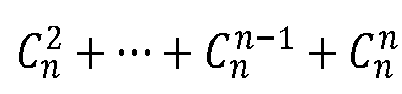
  • Step 3 the electric vehicle selects one or more charging piles along the shortest path l z to reserve charging respectively, and the selection method is as follows: assuming that there are n charging piles distributed along the shortest path l z , there are ( C n 1 + C n 2 + ⁇ + C n n ⁇ 1 + C n n ) charging pile combinations selected for charging by the electric vehicle, and any charging pile combination is selected or the charging pile combination with the least number of the charging piles is reserved for charging.
  • t 0 denotes the departure time of the electric vehicle
  • t 0, w denotes the estimated driving duration of the electric vehicle along the shortest path l z from the departure place O to the charging pile j w
  • the sum of the pre-reserved charging duration refers to the cumulative value of the estimated reserved charging duration that has reserved for charging at other charging piles along the path when the electric vehicle arrives at the charging pile j w along the shortest path l z from the departure place O
  • the sum of the pre-queuing charging duration refers to the cumulative value of the estimated queuing charging duration that has reserved for charging at other charging piles along the path when the electric vehicle arrives at the charging pile j w along the shortest path l z from the departure place O.
  • the remaining electric quantity RE i ( t w ) of the electric vehicle at the time t w when the electric vehicle arrives at the charging pile j w is estimated according to the following Equation 7-1:
  • RE i t w bat _ cap str + the sum of the pre-reserved allocated electric quantity ⁇ EC 0 , w
  • bat_cap str is an initial remaining electric quantity when the electric vehicle departs; the sum of the pre-reserved allocated electric quantity refers to the cumulative value of the reserved allocated electric quantity at other charging piles along the path up to the time t w when the electric vehicle arrives at the charging pile j w from the departure place O along the shortest path l z ; EC 0, w indicates the estimated energy consumption of the electric vehicle driving along the shortest path l z from the departure place O to the charging pile j w .
  • the reserved allocated electric quantity of the electric vehicle at the charging pile j w is TP w
  • the specific step of the method for estimating the reserved allocated electric quantity TP w is as follows:
  • the electric-quantity-based path planning method further includes Step (10-1-5), wherein every time a ⁇ t time passes, the dispatching system platform executes from Step (10-1-2) to Step (10-1-4) according to the re-updated reserved service list of the charging pile j w , and re-estimates the reserved allocated electric quantity TP w .
  • the reserved allocated electric quantity of the electric vehicle at the charging pile j w is TP w
  • the specific step of the method for estimating the reserved allocated electric quantity TP w is as follows:
  • the time t w when the electric vehicle arrives at the charging pile j w is replaced with t w - ⁇ or t w + ⁇ , where ⁇ is a user-defined duration value.
  • An electric quantity reserving method of an energy storage charging pile includes the following steps:
  • the energy storage charging pile announces the type of each idle period of the pile and the corresponding allocable electric quantity in Step (2), and the specific method is as follows:
  • the method for announcing the type of the idle period t 1 ⁇ t 2 further includes: every time a ⁇ t time passes, the dispatching system platform re-estimates the comprehensive energy storage electricity quantity ⁇ t 1 ° t 2 p storage t ⁇ d t of the charging pile j w in Equation 9-1, re-estimates and announces the electricity quantity according to Equation 9-1, and updates the reserved service list of the charging pile j w .
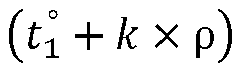
  • the method for announcing the allocable electricity quantity idle period of the energy storage charging pile j w further includes: every time a ⁇ t time passes, the dispatching system platform re-estimates the comprehensive energy storage electricity quantity ⁇ t 1 ° t 1 ° + k ⁇ ⁇ p storage t ⁇ d t and ⁇ t 3 ° t 2 p storage t ⁇ d(t) of the charging pile j w in Equation 9-2 and its constraint conditions, re-estimates and announces the electricity quantity according to Equation 9-3, and updates the reserved service list of the charging pile j w .
  • the present disclosure has the following beneficial effects.
  • Method 1 Method for obtaining the path distance of segments:
  • the dispatching system platform obtains all the charging piles distributed along the path l z .
  • the directed sequence matrix of the n charging piles along the path l z from the departure place O is denoted as ( j 1 , j 2 , ⁇ j n ) T .
  • T is used to denote the segmented point directed sequence matrix of the path l z in which the departure place O, n charging piles distributed along the path and the destination D serve as the segmented points, where j 0 corresponds to the departure place O, and j n +1 corresponds to the destination D.
  • the dispatching system platform obtains the path distance j 0 ,i 1 , ...,j n , j n +1 ) T between two adjacent segmented points from the existing map respectively.
  • the obtained segmented path distance is denoted by the directed sequence matrix ( dist 0 , 1 , dist 1,2 , ⁇ dist n -1 ,n, dist n,n +1 ) T , where dist o , l denotes the path distance from the departure place O to the first charging pile j 1 , dist 1,2 denotes the path distance from the first charging pile j 1 to the second charging pile j 2 , and so on, dist n,n +1 denotes the path distance from the n-th charging pile j n to the destination D.
  • Method 2 Method for estimating the driving time of the segmented path of the electric vehicle i:
  • dist w -1 ,w denotes the path distance from the segmented point j w -1 to the segmented point j w obtained by the method 1.
  • v w denotes the average speed of the electric vehicle i from the segmented point j w -1 to the segmented point j w
  • v w can be the average speed of the electric vehicle i passing through dist w -1, w in the historical statistical period extracted from traffic historical big data, or the average speed of all vehicles passing through dist w -1 ,w in the historical statistical period extracted from traffic historical big data, and the value of the historical statistical period is user-defined.
  • the driving time t w -1, w of the electric vehicle i can also be obtained directly from the existing GIS map.
  • Method 3 One of the following two methods can be selected to estimate the energy consumption of the segmented path of the electric vehicle i :
  • Equation 3-1 EC w -1 ,w denotes the estimated energy consumption of the electric vehicle i from the segmented point j w -1 to the segmented point j w , and the segmented points j w -1 and the segmented point j w are obtained by the method 1.
  • dist w -1 ,w is defined as in Equation 2-1.
  • Aver is the power consumption per unit mileage of the electric vehicle i .
  • Aver m vehicle + m negative ⁇
  • Equation 3-3 S max is the maximum endurance mileage of the model of the electric vehicle i provided by the manufacturer, bat_cap i is the rated capacity of the power battery of the electric vehicle i , and m vehicle is defined as in Equation 3-2.
  • Equation 3-4 EC w -1 ,w is defined as in Equation 3-1, dist w -1 ,w is defined as in Equation 2-1, and kWh is the power consumption per 100 kilometers of the electric vehicle i , which can be obtained from factory parameters or from traffic history big data.
  • Equation 4-1 P w out denotes the constant output power of the charging pile j w , and TP w is the reserved allocated electric quantity of the electric vehicle i at the charging pile j w estimated by the method 10.
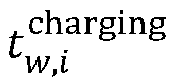
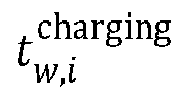
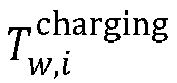
  • Equation 5-1 t w , i charging is the reserved charging start time estimated by the method 10
  • t w is the time when the electric vehicle i arrives at the charging pile j w which is estimated by the method 6.
  • t w t 0 + the sum of the pre-reserved charging duration + the sum of the pre-queuing charging duration + t 0 , w ⁇ w ⁇ 1 n
  • t 0 denotes the departure time of the electric vehicle i
  • t 0 ,w denotes the driving duration of the electric vehicle i along the path l z from the departure place O to the charging pile i w
  • t 0 ,w is obtained by estimating the driving time of each segmented path along the path l z from the departure place O to the charging pile j w by the method 2 and then accumulating the driving time
  • the sum of the pre-reserved charging duration refers to the sum of the reserved charging duration that has reserved for charging at other charging piles along the path when the electric vehicle i arrives at the charging pile j w along the path l z from the departure place O, and the charging durations of other charging piles along the path are obtained by the method 4, respectively
  • the sum of the pre-queuing charging duration refers to the sum of the queuing charging duration that has reserved for charging at other charging piles along the path when the electric vehicle i arrives at the charging pile j w along the
  • RE i t w bat _ cap str + the sum of the pre-reserved allocated electric quantity ⁇ EC 0 , w ⁇ w ⁇ 1 n
  • bat_cap str is an initial remaining electric quantity when the electric vehicle i departs;
  • the sum of the pre-reserved allocated electric quantity refers to the sum of the electric quantity that has reserved for allocation at other charging piles along the path when the electric vehicle i arrives at the charging pile j w from the departure place O along the path l z , and the reserved allocated electric quantity at other charging piles along the path is estimated by the method 10, respectively;
  • EC 0, w indicates the energy consumption of the electric vehicle i driving along the path l z from the departure place O to the charging pile j w
  • EC 0,w is obtained by estimating the segmented path energy consumption of the electric vehicle i by the method 3 and then accumulating the energy consumption.
  • the power supply source of the energy storage charging pile is new energy power generation, including one or more of solar power generation and wind power generation, and may also include complementary energy storage for purchasing electricity from the power grid.
  • Equation 8-1 The constraint condition of Equation 8-1 is: ( t 2 - t 1 ) ⁇ E rated ; where E rated is the rated electricity quantity of the energy storage battery of the charging pile j w ; t 1 is the energy storage start time; t 2 is the energy storage end time; p storage ( t ) is the predicted energy storage power of the energy storage charging pile j w at the time t; if the power supply source of the energy storage charging pile is solar power generation, p storage ( t ) is the predicted output power of solar power generation at the time t, which is predicted by the prior art method; if the power supply source of the energy storage charging pile is wind power generation, p storage ( t ) is the predicted output power of wind power generation at the time t, which is predicted by the prior art method; if the power supply source of the energy storage charging pile is complementary energy storage for purchasing electricity from the power grid, p storage ( t ) is the constant output power of the power grid; if the power supply source
  • the dispatching system platform re-estimates the comprehensive energy storage electricity quantity E ( t 2 - t 1 ) of the charging pile j w .
  • Method 9 The method for announcing the type of the idle period of the charging pile j w and the corresponding allocable electric quantity has the following steps:
  • the energy storage period of the energy storage charging pile j w means that in order not to affect the charging amount of other vehicles that have reserved for charging after the energy storage period and the reserved charging start and end time, the electric vehicle charging cannot be arranged only as the energy storage period of this pile in the idle period, and the energy storage period of the energy storage charging pile j w includes the energy storage start time and the energy storage end time;
  • the allocable electricity quantity idle period is the remaining idle period of the energy storage charging pile j w after excluding the energy storage period from all idle periods in the reserved service list, including the charging start time and the charging end time of the electric vehicle in the allocable electricity quantity idle period;
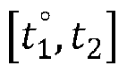
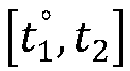
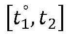
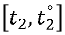
  • the reserved service list of the charging pile j w is searched for the idle period, as shown in FIG. 1 . If vehicles have reserved for charging before and after the idle period t 1 ° t 2 , if a preceding vehicle i 1 has reserved for charging in the period t 1 t 1 ° , the reserved allocated electric quantity is TP 1 ; a preceding vehicle i 2 has reserved for charging in the period t 2 t 2 ° , the reserved allocated electric quantity is TP 2 ; where t 1 and t 1 ° correspond to the reserved charging start time and the reserved charging end time of the preceding vehicle i 1 respectively, and where t 2 and t 2 ° correspond to the reserved charging start time and the reserved charging end time of the preceding vehicle i 2 respectively; t 1 ⁇ t 1 ° ⁇ t 2 ⁇ t 2 ° .
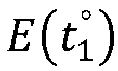
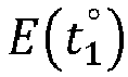
  • E ( t 1 ) , E t 1 ° , E( t 2 ) and E t 2 ° correspond to the estimated remaining electric quantity of the charging pile j w at the time t 1 , t 1 ° , t 2 and t 2 ° .
  • t 1 ° t 2 is announced to be the energy storage period of the energy storage charging pile j w . No vehicle can be reserved for charging or be charged in this energy storage period.
  • t 1 ° is the energy storage start time of the energy storage charging pile j w
  • t 2 is the energy storage end time of the energy storage charging pile j w .
  • E rated is the rated electricity quantity of the energy storage battery of the energy storage charging pile j w
  • p storage ( t ) is the predicted energy storage power of the energy storage charging pile j w at the time t, which is predicted by the prior art method as in the method 8.
  • the dispatching system platform re-estimates the comprehensive energy storage electricity quantity ⁇ t 1 ° t 2 p storage t ⁇ d t of the charging pile j w in Equation 9-1, re-estimates and announces the electricity quantity according to Equation 9-1, and updates the reserved service list of the charging pile j w .
  • the method for announcing the allocable electric quantity idle period of the energy storage charging pile j w includes the following steps.
  • the allocable electric quantity idle period is divided into time points according to a fixed duration ⁇ , where ⁇ is a user-defined constant. If there is an allocable electric quantity idle period is 9: 00-10: 15 and ⁇ is user-defined for 30 minutes, the period can be divided into four time points, namely 9: 00, 9: 30, 10: 00 and 10: 15. The latest charging end time of the electric vehicle at each time point and the allocable electric quantity can be announced respectively.
  • the announcing method is as follows.
  • the allocable electricity quantity idle period of the energy storage charging pile j w must meet the following Equation 9-2: TP 2 ⁇ E t 1 ° + ⁇ t 1 ° t 1 ° + k ⁇ ⁇ p storage t ⁇ d t ⁇ P w out ⁇ t 3 ° ⁇ t 1 ° + k ⁇ ⁇ + ⁇ t 3 ° t 2 p storage t ⁇ d t
  • Equation 9-2 The constraint condition of Equation 9-2 is: ⁇ 0 ⁇ E t 2 ° ⁇ E rated 0 ⁇ E t 2 ⁇ E rated 0 ⁇ E t 1 ° + ⁇ t 1 ° t 1 ° + k ⁇ ⁇ p storage t ⁇ d t ⁇ E rated P w out ⁇ t 3 ° ⁇ t 1 ° + k ⁇ ⁇ ⁇ E t 1 ° + ⁇ t 1 ° t 1 ° + k ⁇ ⁇ p storage t ⁇ d t t 1 ⁇ t 1 ° ⁇ t 1 ° + k ⁇ ⁇ ⁇ t 3 ° ⁇ t 2 ⁇ t 2 °
  • Equation 9-2 p storage ( t ) is the predicted energy storage power of the energy storage charging pile j w at the time t, which is predicted by the prior art method as in the method 8; P w out is a constant output power of the charging pile j w ; E rated is the rated electricity quantity of the energy storage battery of the energy storage charging pile j w .
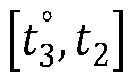
  • t 3 ° t 2 is the energy storage period of the energy storage charging pile j w .
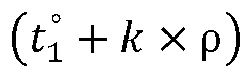
  • the corresponding allocable electric quantity Q w ( t ) at the time point t 1 ° + k ⁇ ⁇ in the allocable electricity quantity idle period t 1 ° t 2 is announced in the reserved service list of the energy storage charging pile j w .
  • the rest of the time points are announced according to the method announced at the time point t 1 ° + k ⁇ ⁇ .
  • the dispatching system platform re-estimates the comprehensive energy storage electricity quantity ⁇ t 1 ° t 1 ° + k ⁇ ⁇ p storage t ⁇ d t and ⁇ t 3 ° t 2 p storage t ⁇ d t of the charging pile j w in Equation 9-2, re-estimates and announces the electricity quantity according to Equation 9-2 and its constraint conditions, and Equation 9-3, and updates the reserved service list of the charging pile j w .
  • Method 10 The allocable electric quantity Q w ( i ) that the charging pile j w can supply to the electric vehicle i , the reserved charging start time t w , i charging of the electric vehicle i at the charging pile j w , the reserved charging duration T w , i charging of the electric vehicle i at the charging pile j w , and the reserved allocable electricity quantity TP w of the electric vehicle i at the charging pile j w are estimated, respectively:
  • Estimation method 1 when the charging pile j w is an energy storage charging pile, the specific steps of the estimation method are as follows.
  • the constraint condition of the equation set 10-2 is as follows: 0 ⁇ E t 1 ° + ⁇ t 1 ° t w , i charging p stroage t ⁇ d t ⁇ E rated
  • TP w min Q w t w , i charging , bat _ cap i ⁇ RE i t w
  • T w , i charging TP w ⁇ P w out
  • t w i charging is the reserved charging start time of the electric vehicle i at the charging pile j w ;
  • t w is the estimated time when the electric vehicle i arrives at the charging pile j w ;
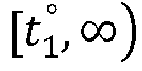
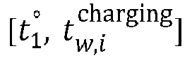
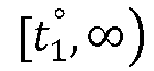
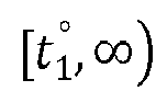
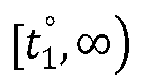
  • Q w t w i charging is the estimated allocable electricity quantity of the charging pile j w in [ t 1 ° , ⁇ ) ;
  • E t 1 ° is the estimated remaining electric quantity of the charging pile j w at the reserved charging end time t 1 ° corresponding to the preceding vehicle i 1 ;
  • p storage ( t ) is the predicted energy storage power of the charging pile j w at the corresponding time t , which is predicted by the prior art method as in the method 8;
  • ⁇ t 1 ° t 1 ° + k ⁇ ⁇ p storage t ⁇ d t is the predicted comprehensive energy storage electricity quantity of the charging pile j w at the period
  • the precondition for the charging pile j w to allow the electric vehicle i to jump a queue to reserve for charging in the allocable electricity quantity idle period t 1 ° t 2 is to not affect the reserved allocated electricity quantity and the reserved charging start and end time of other preceding vehicles that have already reserved for charging after this period t 1 ° t 2 , as shown in the method 9, that is, the charging and discharging of the charging pile j w in the reserved charging period t 2 t 2 ° must first meet the following Equation 10-5: TP 2 ⁇ E t 1 ° + ⁇ t 1 ° t w , i charging p storage t ⁇ d t ⁇ P w out ⁇ t 3 ° ⁇ t w , i charging + ⁇ t 3 ° t 2 p storage t ⁇ d t
  • Equation 10-5 The constraint condition of Equation 10-5 is: ⁇ E t 1 ° + ⁇ t 1 ° t w , i charging p storage t ⁇ d t ⁇ P w out ⁇ t 3 ° ⁇ t w , i charging + ⁇ t 3 ° t 2 p storage t ⁇ d t ⁇ E rated 0 ⁇ E t 1 ° + ⁇ t 1 ° t w , i charging p stoarage t ⁇ d t ⁇ E rated p w out ⁇ t 3 ° ⁇ t w , i charging ⁇ E t 1 ° + ⁇ t 1 ° t w , i charging p storage t ⁇ d t t 1 ⁇ t 1 ° ⁇ t w , i charging ⁇ t 3 ⁇ t 2 °
  • the latest charging end time t 3 ° of the electric vehicle i can be calculate when the charging pile j w allows the electric vehicle i to jump a queue for charging in the reserved charging period t 1 ° t 2 .
  • the condition for the charging pile j w to allow the electric vehicle i to jump a queue to reserve for charging in the allocable electricity quantity idle period t 1 ° t 2 is that in addition to ensuring that the reserved allocated electricity quantity TP 2 of the preceding vehicle i 2 in the reserved charging period t 2 t 2 ° remains unchanged, it is also necessary to ensure that the reserved start and end time and the reserved allocated electricity quantity of all other preceding vehicles remain unchanged, and the specific methods are as follows.
  • t 4 and t 4 ° correspond to the reserved charging start time and the reserved charging end time of the preceding vehicle i 4 , respectively.
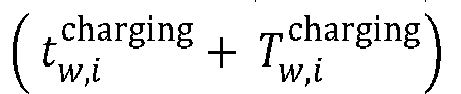
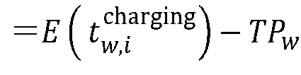
  • the reserved allocated electric quantity is TP 4 , in which t 2 ⁇ t 2 ° ⁇ t 4 ⁇ t 4 ° , TP w also meets the following Equation 10-10: TP 4 ⁇ E t 1 ° + ⁇ t 1 ° t w , i charging p storage t ⁇ d t ⁇ TP w + ⁇ t w , i charging + T w , i charging t 2 p storage t ⁇ d t ⁇ TP 2 + ⁇ t 2 ° t 4 p storage t ⁇ d t
  • Equation 10-10 If TP w does not meet Equation 10-10, TP w is reduced, and the corresponding T w , i charging is also reduced according to Equation 10-9 but t w , i charging remains unchanged until Equation 10-10 is met.
  • the preceding vehicles are processed according to the method of the preceding vehicle i 4 respectively until TP w can ensure that the reserved allocated electric quantity of all other preceding vehicles i 2 , i 4 , i 5 , i 6 whil remain unchanged.
  • TP 2 is the reserved allocated electricity quantity of the preceding vehicle i 2 in the reserved charging period t 2 t 2 °
  • E t 1 ° is the remaining electric quantity of the charging pile j w at the reserved charging end time t 1 ° corresponding to the preceding vehicle i 1
  • p storage ( t ) is the predicted energy storage power of the charging pile j w at the corresponding time t , which is predicted by the prior art method
  • P w out is a constant output power of the charging pile j w
  • t w i charging is the reserved charging start time of the electric vehicle i at the charging pile j w
  • t w is the estimated time when the electric vehicle i arrives at the charging pile j w
  • E rated is the rated electricity quantity of the energy storage battery of the charging pile j w
  • t 3 ° is the latest charging end time of the electric vehicle i when the charging pile j
  • Step (10-1-5) every time a ⁇ t time passes, the dispatching system platform executes from Step (10-1-2) to Step (10-1-4) according to the re-updated reserved service list of the charging pile j w , and re-estimates the reserved allocated electric quantity TP w .
  • Estimation method 2 when the charging pile j w is a power-grid direct-supply charging pile, the specific estimation method is as follows.
  • TP w bat _ cap i ⁇ RE i t w
  • bat_cap i is the rated electricity quantity of the power battery of the electric vehicle i
  • RE i ( t w ) is the estimated remaining electric quantity of the electric vehicle i at the time t w when the electric vehicle arrives at the charging pile j w ;
  • the idle periods of the power-grid direct-supply charging piles are all rechargeable periods of the electric vehicles, so that the allocable electric quantity Q w ( i ) that the charging piles j w can supply to the electric vehicles i is replaced by the rechargeable periods t 1 ° t 2 of the charging pile j w .
  • TP w min bat _ cap i ⁇ RE i t w , P w out ⁇ t 2 ⁇ t w , i charging
  • bat_cap i is the rated electricity quantity of the power battery of the electric vehicle i
  • RE i ( t w ) is the estimated remaining electric quantity of the electric vehicle i at the time t w when the electric vehicle arrives at the charging pile j w
  • P w out is a constant output power of the charging pile j w
  • t w i charging is the reserved charging start time of the electric vehicle i at the charging pile j w .
  • the fused use of an energy storage charging pile and a power-grid direct-supply charging pile is realized using arrival time matching and energy time differentiation, which improves the integrity of the charging pile network and lays the foundation for fast charging network.
  • the types of the charging piles in the whole road network of this embodiment include the existing energy storage charging piles, and can also include the existing power-grid direct-supply charging piles directly supplied by the power grid to the electric vehicles for charging.
  • the power supply source of the energy storage charging pile can be one or more of new energy generation or complementary energy storage for purchasing electricity from the power grid.
  • the new energy generation includes solar power generation and wind power generation.
  • the electric vehicle carries out direct current charging through the energy storage charging pile, which is referred to as fast charging for short.
  • a control module for automatically switching working modes is arranged in the energy storage charging pile. When an electric vehicle is connected with the charging pile for charging, the control module controls to switch to the charging pile discharging working mode. When no electric vehicle is connected for charging, the control module controls to automatically switch to the charging pile energy storage working mode.
  • the present disclosure provides an electric-quantity-based path planning method for the electric vehicle compatible with the energy storage charging pile.
  • the electric vehicle is an electric car, and the method includes the following steps.
  • Step 3 if the reserved allocated electric quantity of each reserved charging pile along the path cannot meet the endurance requirement of the electric vehicle for driving from the departure place O to the destination D, a mobile charging vehicle is sent to the path to supplement the reserved allocated electric quantity of the electric vehicle until the endurance requirement of the electric vehicle for driving from the departure place O to the destination D is met.
  • the method of finding the shortest path is not only to obtain the path from the electronic map, but also can be calculated by many traditional algorithms such as dijkstra algorithm.
  • the current electronic navigation map also provides the fastest arrival path after considering the road conditions, and can also use the present disclosure to replace the shortest path for calculation.
  • the shortest path planned according to the method of this embodiment meets the requirements of energy consumption saving, as well as the needs of users and low-carbon society.
  • the charging piles of the whole road network in this embodiment are the same as those in Embodiment 1.
  • the present disclosure provides an electric-quantity-based path planning method for the electric vehicle compatible with the energy storage charging pile.
  • the electric vehicle is an electric car, and the method includes the following steps.
  • All the charging piles in the road network submit the state information of this pile to the dispatching system platform, respectively, including: the position of this charging pile, the type of this pile, the rated electricity quantity E rated of the energy storage battery of this charging pile, the real-time occupation status of this charging pile, and the real-time energy storage electricity quantity of this charging pile if it is an energy storage charging pile.
  • the electric vehicle client of the electric vehicle i puts forward a reservation application to the dispatching system platform.
  • the reservation application includes the following information: an electric vehicle user name, an electric vehicle brand, an vehicle model, a departure time t 0 , a departure place O, a destination D, an initial remaining electric quantity bat_cap str of the power battery at the departure time of the electric vehicle, and an rated electric quantity bat_cap i of the power battery of the electric vehicle i .
  • the dispatching system platform establishes and stores a reserved service list for each charging pile, respectively, and the field contents of the reserved service list include an electric vehicle user name, an electric vehicle brand, an vehicle model, reserved charging start time and charging pile remaining electric quantity corresponding to the time, reserved charging end time and charging pile remaining electric quantity corresponding to the time, reserved allocated electric quantity, charging duration, a type of the idle periods and corresponding allocable electricity quantity.
  • the directed sequence matrix ( j 1 , j 2 , ⁇ j n ) T of the charging piles distributed along the path l z is obtained by the above method 1, any of ( C n 1 + C n 2 + ⁇ + C n n ⁇ 1 + C n n ) charging pile combinations that can be charged for charging by the electric vehicle i is selected. Assuming that ( j x 1 , j x 2 , ⁇ j xk ) T , the electric vehicle i is reserved for charging at each charging pile in ( j x 1 , j x 2, ⁇ j xk ) T .
  • the energy consumption of the segmented path of the electric vehicle i is estimated according to the above method 3.
  • bat_cap str is the initial remaining electric quantity of the power battery at the departure time t 0 of the electric vehicle i ;
  • EC 0, n +1 denotes the estimated whole-journey energy consumption of the electric vehicle i along the shortest path l z from the departure place O to the destination D, which is accumulated after estimating the energy consumption of the segmented path of the electric vehicle i by the above method 3.
  • the whole-journey reservation scheme includes assigning the charging pile combination ( j x 1 , j x 2 , ⁇ j xk ) T distributed along the shortest path l z to reserve the electric vehicle i for charging in sequence, which corresponds to the reserved allocated electric quantity ( TP x 1 , TP x 2 , ⁇ TP xk ) T , as well as the reserved charging start and end time of each reserved charging pile.
  • the reserved service list of each charging pile j w in ( j x 1 , j x 2 , ⁇ j xk ) T is updated according to the whole-journey reservation scheme and Step 4).
  • the dispatching system platform guides the electric vehicle to travel and charge according to the whole-journey reservation scheme.
  • the charging pile combination ( j x 1 , j x 2 , ⁇ j xk ) T is excluded from the charging pile combination of C n 1 + C n 2 + ⁇ + C n n ⁇ 1 + C n n electric vehicles i that can be selected for charging in Step 3).
  • Step 7 If all the charging pile combination of ( C n 1 + C n 2 + ⁇ + C n n ⁇ 1 + C n n ) electric vehicles i that can be selected for charging in Step 3) have been excluded, it means that the path l z does not meet the whole-journey endurance requirements, and then proceed to Step 7). Otherwise, another combination is selected from the remaining combination after excluding the charging pile combination ( j x 1 , j x 2 , ⁇ j xk ) T from the charging pile combination of C n 1 + C n 2 + ⁇ + C n n ⁇ 1 + C n n electric vehicles i that can be selected for charging, and proceed to Step 4) to carry out cyclic execution to Step 6).
  • the electric vehicle i may arrive at the reserved charging pile j w in advance or later.
  • the estimated time t w when the electric vehicle i arrives at the charging pile j w can be replaced by t w - ⁇ or t w + ⁇ , where ⁇ is a user-defined duration value. The other methods and steps remain unchanged.
  • N charging pile combinations among the charging pile combination of C n 1 + C n 2 + ⁇ + C n n ⁇ 1 + C n n electric vehicles i that can be selected for charging enables the path l z to meet the whole-journey endurance requirements of the electric vehicle i
  • the combination with the least reserved charging times, that is, the least reserved charging piles is selected to generate the whole-journey reservation scheme. The other methods and steps remain unchanged.
  • charging on the way is a rest stop point
  • the charging pile can be selected by dividing the rest stop point into several time points equally.
  • the combination containing the charging piles that must reserve for charging is selected from ( C n 1 + C n 2 + ⁇ + C n n ⁇ 1 + C n n ) combinations in Step (3) as an alternative.
  • the other methods and steps remain unchanged.
  • the designated operating point has a charging pile, which is used as the charging pile that must reserve for charging, of the logistics electric vehicles.
  • Step (2) only the path containing the charging pile that must reserve for charging can be selected.
  • the combination containing the charging piles that must reserve for charging can only be selected from ( C n 1 + C n 2 + ⁇ + C n n ⁇ 1 + C n n ) combinations in Step (3) as an alternative. The other methods and steps remain unchanged.
  • the dispatching system platform re-announces the idle period type and the corresponding allocable electricity quantity of each energy storage charging pile j w in the charging pile combination ( j x 1 , j x 2 , ⁇ j xk ) T according to the method 9, and updates the reserved service list of each energy storage charging pile j w ; re-estimates the reserved allocated electricity quantity TP w of each energy storage charging pile j w according to the method 10, and re-estimates the time t w when the electric vehicle i arrives at the charging pile j w according to the method 6, and then starts cyclic execution from Step 4) to Step 6) to re-plan the electric-quantity-based path of the electric vehicle.
  • this embodiment if it is a charging station with multiple charging piles, it is only necessary to set the distance between the charging piles in the charging station as a minimum value, for example, 1 meter, which also applies to the method of Embodiment 2 to plan the charging path, so that the electric vehicle i can reserve different charging piles in one charging station for charging.
  • connection structure between some direct current charging piles and power supply is as follows.
  • the alternating current generated by wind generators is converted into direct current and flows into a common direct current bus after rectification, and the direct current generated by photovoltaic power generation flows into the common direct current bus through a transformer, or the mains supply is converted into direct current and flows into the common direct current bus after rectification.
  • the direct current generated by the energy storage batteries of the charging piles flows into the common direct current bus through a transformer.
  • the common direct current bus is connected with an electric vehicle. When the energy storage battery of the charging pile is insufficient, photovoltaic power generation, wind power generation or mains supply can charge the energy storage battery and the electric vehicle at the same time.
  • the electric vehicle is slowly charged, which is equivalent to directly supplying the charging pile to the power grid.
  • the electric vehicle is charged by the energy storage battery of the charging pile.
  • the electric vehicle is fast charged, which is equivalent to the energy storage charging pile.
  • the method of this embodiment is also applicable.
  • the charging piles of the whole road network in this embodiment are the same as those in Embodiment 1.
  • the present disclosure provides an electric-quantity-based path planning method for the electric vehicle compatible with the energy storage charging pile.
  • the electric vehicle is an electric car
  • the method for adjusting the preceding vehicle also includes the following steps.
  • Adjustment method 1) the reserved allocated electric quantity of the preceding vehicle at one or more common piles is cancelled, and the cancelled reserved allocated electric quantity is re-incorporated into the remaining electric quantity of their corresponding charging piles. Thereafter, according to the methods in Steps 3) to 6) of Embodiment 2, it is judged whether the shortest path l z of the electric vehicle i and the path of the original whole-journey reservation scheme of the preceding vehicle meet the whole-journey endurance requirements of the electric vehicle i and the preceding vehicle, respectively, wherein if so, the dispatching system platform generates a whole-journey reservation scheme for the electric vehicle i , and generates a new whole-journey reservation scheme for the preceding vehicle, and the adjustment is successful; if the path does not meet the endurance requirement of the electric vehicle i and the preceding vehicle, it is impossible to adjust the preceding vehicle and restore the original whole-journey reservation scheme of the preceding vehicle.
  • Adjustment method 2 the reserved allocated electric quantity of the preceding vehicle at one or more common piles is reduced.
  • the sum of the reserved allocated electric quantity reduced by the preceding vehicle is greater than or equal to the electric quantity ⁇ TP i that the electric vehicle i is expected to lack when driving to the next segmented point j w +1 after reserving electric quantity at the charging pile j w
  • ⁇ TP i is estimated according to the following Equation 3-1-1:
  • ⁇ TP i EC w , w + 1 ⁇ RE i t w ⁇ TP w
  • EC w,w +1 denotes the energy consumption of the electric vehicle i from the current charging pile j w to the next charging pile
  • t w is the estimated time when electric vehicle i arrives at the charging pile j w
  • RE i ( t w ) is the estimated remaining electric quantity of the electric vehicle i at the time t w when the electric vehicle arrives at the charging pile j w
  • Steps 3) to 6) of Embodiment 2 it is judged whether the shortest path l z of the electric vehicle i and the path of the original whole-journey reservation scheme of the preceding vehicle meet the whole-journey endurance requirements of the electric vehicle i and the preceding vehicle, respectively, wherein if so, the dispatching system platform generates a whole-journey reservation scheme for the electric vehicle i , and generates a new whole-journey reservation scheme for the preceding vehicle, and the adjustment is successful; if the path does not meet the endurance requirement of the electric vehicle i and the preceding vehicle, it is impossible to adjust the preceding vehicle and restore the original whole-journey reservation scheme of the preceding vehicle.
  • Charging scheduling is performed on the vehicle through the dispatching system platform.
  • the original disorderly reservation specified by a user based on the pile position is upgraded to the unified planning and allocation by the scheduling platform based on the energy demand of the users in the whole network and the charging pile resources, and the users are subjected to mandatory scheduling, thus maximizing the resource utilization and meeting the driving needs of more vehicles.
  • the charging piles of the whole road network in this embodiment are the same as those in Embodiment 1.
  • the present disclosure provides an electric-quantity-based path planning method for the electric vehicle compatible with the energy storage charging pile.
  • the electric vehicle is an electric car
  • the correcting method also includes the following steps.
  • the electric vehicle generates the whole-journey reservation scheme according to the electric-quantity-based path planning method for the electric vehicle compatible with the energy storage charging pile in Embodiment 2 or 3.
  • the whole-journey reservation scheme of the electric vehicles is to reserve in advance, in order to prevent the great changes of the actual vehicle parameters or charging pile parameters at the time of departure or after departure and during reservation from affecting the smooth travel and charging of the electric vehicles according to the whole-journey reservation scheme, the following correction methods are used to correct the whole-journey reservation scheme of the electric vehicles, respectively.
  • Correction method 1 if the parameters determined before the electric vehicle departs, including departure time, on-board mass m negative and the initial remaining electric quantity of the power battery of the electric vehicle, are different from the information submitted when applying for reservation, the determined parameters are resubmitted to the dispatching system platform, and the dispatching system platform uses the electric-quantity-based path planning method of Embodiment 2 or Embodiment 3 to regenerate the whole-journey reservation scheme according to the determined parameters.
  • the dispatching system platform guides the electric vehicle to travel and charge according to the new whole-journey reservation scheme. If the electric-quantity-based path planning method in Embodiment 2 or Embodiment 3 cannot generate a new whole-journey reservation scheme, the reservation fails.
  • Correction method 2 after the electric vehicle departs and travels for a period of time or distance, the electric vehicle calculates the average driving speed, average energy consumption and vehicle load according to the actual driving parameters including the change of the remaining electric quantity of the power battery of the electric vehicle and the mileage, and submits them to the dispatching system platform again.
  • the dispatching system platform uses the electric-quantity-based path planning method of Embodiment 2 or Embodiment 3 to regenerate the whole-journey reservation scheme to guide the electric vehicle to travel and charge according to the actual parameters.
  • the actual parameters can be obtained through the self-detection of the electric vehicle and reported to the dispatching system platform through the wireless network, the driver's telephone or the vehicle terminal voice, or reported to the dispatching system platform after being estimated by the driver according to the experience value.
  • Correction method 3 whenever the dispatching system platform generates a whole-journey reservation scheme for an electric vehicle, or after the electric vehicle is charged according to the whole-journey reservation scheme, the dispatching system platform updates the service list content of the corresponding reserved charging pile.
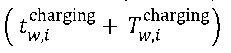
  • Correction method 4 it is known that the whole-journey reservation scheme of the electric vehicles includes the estimated time t w arriving at the charging pile j w , the estimated reserved allocated electric quantity TP w of the electric vehicle at the charging pile j w , the charging duration T w , i charing of the electric vehicles at the charging pile j w , the reserved charging start time t w , i charing and the remaining electric quantity E t w , i charging corresponding to the charging pile, the reserved charging end time t w , i charging + T w , i charging and the remaining electric quantity E t w , i charging + T w , i charging corresponding to the charging pile.
  • the map software on the vehicle After the electric vehicle is on the road, during the travel, the map software on the vehicle provides the current position P a , the current time t a , the distance D aw from the nearest reserved charging pile j w , and the driving time t aw from P a to j w in real time.
  • the estimated time to arrive at the charging pile j w and the reserved charging start time are modified as both (t a +t aw ).
  • the reserved charging duration and the reserved allocated electric quantity at the charging pile j w are unchanged, so that the whole-journey reservation scheme of the electric vehicle is updated.
  • the original reservation of the electric vehicle at the charging pile j w is cancelled, and then the reserved service list of the charging pile j w is updated.
  • the dispatching system platform informs the user that the reservation at the charging pile j w cannot be modified, and the electric vehicle should apply to the dispatching system platform for re-planning a new electric-quantity-based path according to the electric-quantity-based path planning method for the electric vehicle compatible with the energy storage charging pile in Embodiment 2 or 3.
  • An electric quantity reserving method of an energy storage charging pile includes the following steps.
  • this energy storage charging pile is connected to the dispatching system platform through wireless or wired connection without affecting the reserved service list of this pile, and participates in the overall management of the dispatching system platform according to the electric-quantity-based path planning method of Embodiment 2, 3 or 4, just like other energy storage charging piles in the whole network.
  • the energy storage charging piles in the whole network in Embodiment 2, 3 or 4 can provide electric quantity reservation for the electric vehicle according to the electric quantity reserving method of the energy storage charging pile in Embodiment 5 without affecting their respective reserved service lists.
  • the multi-user charging behavior of the energy storage charging pile and the discharging behavior of the energy storage charging pile are unified in the time dimension, and the multi-user reservation of the energy storage charging pile is realized.
  • Embodiments 1 to 5 of the present disclosure is not only suitable for an electric vehicle, but also suitable for an unmanned aerial vehicle or unmanned ships. Reservation and electric-quantity-based path planning are made after considering modification of the airworthiness area and meteorological conditions.

Landscapes

  • Business, Economics & Management (AREA)
  • Engineering & Computer Science (AREA)
  • Human Resources & Organizations (AREA)
  • Economics (AREA)
  • Strategic Management (AREA)
  • General Physics & Mathematics (AREA)
  • Tourism & Hospitality (AREA)
  • Physics & Mathematics (AREA)
  • General Business, Economics & Management (AREA)
  • Marketing (AREA)
  • Theoretical Computer Science (AREA)
  • Entrepreneurship & Innovation (AREA)
  • Remote Sensing (AREA)
  • Radar, Positioning & Navigation (AREA)
  • Quality & Reliability (AREA)
  • Operations Research (AREA)
  • Development Economics (AREA)
  • Health & Medical Sciences (AREA)
  • Game Theory and Decision Science (AREA)
  • General Health & Medical Sciences (AREA)
  • Primary Health Care (AREA)
  • Public Health (AREA)
  • Water Supply & Treatment (AREA)
  • Automation & Control Theory (AREA)
  • Educational Administration (AREA)
  • Charge And Discharge Circuits For Batteries Or The Like (AREA)
  • Navigation (AREA)

Abstract

The present disclosure discloses an electric-quantity-based path planning method for an electric vehicle compatible with an energy storage charging pile. The method includes the following steps: 1) charging piles in a whole network submitting state information of the piles to a dispatching system platform, and before departure, an electric vehicle applying for a reservation from the dispatching system platform; 2) finding a shortest path from a departure place to a destination; 3) the dispatching system platform judging whether the reserved allocated electric quantity of the electric vehicle at one or more charging piles along the path meets an endurance requirement for driving to the destination; 4) if so, generating a whole-journey reservation scheme; and 5) if not, excluding the shortest path, and finding the shortest path from the remaining paths, and performing cyclic execution from Step 3) until all paths are traversed. By means of the method of the present disclosure, whole-journey electric-quantity-based path planning for an electric vehicle can be realized, the fused use of an energy storage charging pile and a power-grid direct-supply charging pile is realized using arrival time matching, and charging scheduling is also performed on the vehicle through the dispatching system platform, such that the electric quantity of the charging pile resources, especially an energy storage pile, in a whole network is fully utilized.

Description

    TECHNICAL FIELD
  • The present disclosure belongs to the field of an electric-quantity-based path planning method for an electric vehicle, in particular to an electric-quantity-based path planning method for an electric vehicle compatible with an energy storage charging pile.
  • BACKGROUND
  • At present, electric vehicles based on new energy sources, such as electric cars, electric boats and unmanned aerial vehicles, have been widely used. There are many charging path planning methods for an electric quantity of an electric vehicle in the prior art, but they are basically only suitable for power-grid direct-supply charging piles or charging stations. Most of the existing charging path planning for an electric vehicle is to find a next rechargeable charging station for users to choose by themselves according to detecting the remaining electric quantity of the current power battery of the electric vehicles. When it is necessary to charge for many times to reach the destination in a long distance, there is no reasonable and effective whole-journey electric-quantity-based path planning method. An energy storage charging pile has the advantages of slow storage and quick discharge. However, due to the limited energy storage of the energy storage charging pile or charging station, the idle period is not equal to the effective charging period with enough energy storage, and there is no effective reserving method at present. Furthermore, for the road network including energy storage charging piles or charging stations, it is also an unsolved problem at present about how to realize the fused use of the energy storage charging piles and power grid charging piles in the whole network, and even realize the full utilization of the energy storage electricity quantity of the charging piles in the whole network, especially for serving more electric vehicles.
  • SUMMARY
  • Aiming at the problems existing in the prior art, the present disclosure provides an electric-quantity-based path planning method for an electric vehicle compatible with an energy storage charging pile, which realizes the fused use of an energy storage charging pile and a power-grid direct-supply charging pile using arrival time matching and energy time differentiation, and performs charging scheduling on the vehicle through the dispatching system platform at the same time, such that the electric quantity of the charging pile resources, especially an energy storage electricity quantity of an energy storage charging pile, in a whole network is fully utilized. Another object of the present disclosure is to provide an electric quantity reserving method of an energy storage charging pile, which realize the multi-user reservation of the electric quantity of the energy storage charging pile.
  • The present disclosure uses the following technical scheme to solve the technical problems.
  • The present disclosure relates to an electric-quantity-based path planning method for an electric vehicle compatible with an energy storage charging pile, wherein a power supply source of the energy storage charging pile is complementary energy storage for generating electricity from new energy or purchasing electricity from a power grid, wherein the method includes the following steps:
    1. 1) all charging piles in a whole network submitting state information of the piles to a dispatching system platform, respectively, and before departure, an electric vehicle user applying to the dispatching system platform for a reservation of the electric quantity from departure place O to destination D through network connection, and the electric quantity application reservation includes the following information: an electric vehicle model, a vehicle load quality, a departure time, departure place O, a destination D and a remaining electric quantity of a power battery of an electric vehicle user at the departure time;
    2. 2) the dispatching system platform finding a shortest path lz from a departure place O to a destination D on an existing map, where z=1;
    3. 3) the dispatching system platform judging whether the reserved allocated electric quantity at each reserved charging pile meets an endurance requirement of the electric vehicle for driving from the departure place O to the destination D when the electric vehicle selects one or more charging piles along the shortest path lz to reserve charging respectively according to the state information of the pile submitted by each charging pile and the electric quantity reservation application submitted by the electric vehicle user; if so, executing Step 4), if no, executing Step 5);
    4. 4) the dispatching system platform generating a whole-journey reservation scheme for the electric vehicle, wherein the whole-journey reservation scheme includes assigning each reserved charging pile on the shortest path lz and the corresponding reserved allocated electric quantity for the electric vehicle, and returning information of successful reservation to the electric vehicle user to end the reservation; after the electric vehicle departs from the departure place O, the dispatching system platform guiding the electric vehicle to travel and charge according to the whole-journey reservation scheme;
    5. 5) the dispatching system platform excluding the shortest path lz , where z = z + 1, and then finding a new shortest path lz from the remaining paths from the departure place O to the destination D, executing the Steps 3) to 5) circularly if the new shortest path lz is found, and returning information of failed reservation to the electric vehicle user if the new shortest path lz is not found.
  • In Step 3), the electric vehicle selects one or more charging piles along the shortest path lz to reserve charging respectively, and the selection method is as follows: assuming that there are n charging piles distributed along the shortest path lz , there are ( C n 1 + C n 2 + + C n n 1 + C n n
    Figure imgb0001
    ) charging pile combinations selected for charging by the electric vehicle, and any charging pile combination is selected or the charging pile combination with the least number of the charging piles is reserved for charging.
  • The specific method of judging whether the reserved allocated electric quantity at each reserved charging pile meets an endurance requirement of the electric vehicle for driving from the departure place O to the destination D when the electric vehicle selects one or more charging piles along the shortest path lz to reserve charging respectively in Step 3) is as follows:
    • assuming that the charging pile combination of the electric vehicle reserved to charge in sequence along the shortest path lz be (j x1, jx2 ,··· jxk ) T, judging in sequence whether the reserved allocated electric quantity corresponding to each of the charging piles jw meets an inequality set 2-1-1, wherein if so, the shortest path lz meets the endurance requirement of the electric vehicle for driving from the departure place O to the destination D; otherwise, the shortest path lz does not meet the endurance requirement of the electric vehicle for driving from the departure place O to the destination D;
      { RE i t w + TP w EC w , w + 1 bat _ cap str + w = x 1 xk TP w EC 0 , n + 1 w x 1 , xk
      Figure imgb0002
    • wherein in the inequality set 2-1-1, REi (tw ) is an estimated remaining electric quantity of the electric vehicle at the time tw when the electric vehicle arrives at the charging pile jw, TPw denotes the reserved allocated electric quantity of the electric vehicle at the charging pile jw, EC ww+1 denotes the estimated energy consumption of the electric vehicle from the current charging pile jw to the next charging pile j w+1, if the charging pile jw is the last charging pile in the shortest path lz , EC w,w+1 denotes the estimated energy consumption of the electric vehicle from the current charging pile jw to the destination D; bat_capstr is the initial remaining electric quantity of the power battery at the departure time t 0 of the electric vehicle; w = x 1 xk TP w
      Figure imgb0003
      denotes the sum of the reserved allocated electric quantity of all the reserved charging piles of the electric vehicle at the charging pile combination (j x1 , jx2,··· jxk)T; EC 0,n+1 denotes the estimated whole-journey energy consumption of the electric vehicle along the shortest path lz from the departure place O to the destination D.
  • The time tw when the electric vehicle arrives at the charging pile jw is estimated according to the following Equation 6-1: t w = t 0 + the sum of the pre-reserved charging duration + the sum of the pre-queuing charging duration + t 0 , w
    Figure imgb0004
  • in Equation 6-1, t 0 denotes the departure time of the electric vehicle; t 0,w , denotes the estimated driving duration of the electric vehicle along the shortest path lz from the departure place O to the charging pile jw ; the sum of the pre-reserved charging duration refers to the cumulative value of the estimated reserved charging duration that has reserved for charging at other charging piles along the path when the electric vehicle arrives at the charging pile jw along the shortest path lz from the departure place O; the sum of the pre-queuing charging duration refers to the cumulative value of the estimated queuing charging duration that has reserved for charging at other charging piles along the path when the electric vehicle arrives at the charging pile jw along the shortest path lz from the departure place O.
  • The remaining electric quantity REi (tw ) of the electric vehicle at the time tw when the electric vehicle arrives at the charging pile jw is estimated according to the following Equation 7-1:
    RE i t w = bat _ cap str + the sum of the pre-reserved allocated electric quantity EC 0 , w
    Figure imgb0005
  • in Equation 7-1, bat_capstr is an initial remaining electric quantity when the electric vehicle departs; the sum of the pre-reserved allocated electric quantity refers to the cumulative value of the reserved allocated electric quantity at other charging piles along the path up to the time tw when the electric vehicle arrives at the charging pile jw from the departure place O along the shortest path lz ; EC 0,w indicates the estimated energy consumption of the electric vehicle driving along the shortest path lz from the departure place O to the charging pile jw .
  • The reserved allocated electric quantity of the electric vehicle at the charging pile jw is TPw, and when the charging pile jw is an energy storage charging pile, the specific step of the method for estimating the reserved allocated electric quantity TPw is as follows:
    • (10-1-1), assuming that the electric vehicle is an electric vehicle i, presetting a queuing time limit σ after the time tw when the electric vehicle i arrives at the charging pile jw first, where σ is a user-defined time value;
    • (10-1-2), according to a reserved service list of the charging pile jw , searching types of the idle period of the charging pile jw between tw and tw +σ, wherein if all the found types of the idle period are energy storage periods, the charging pile jw is incapable of reserving for charging the electric vehicle i, that is, the reserved allocated electricity quantity TPw = 0; if the found idle period type is an allocable electricity quantity idle period, proceeding to Step (10-1-3);
    • (10-1-3), searching the reserved service list of the charging pile jw , if the idle period of the charging pile jw between tw and tw +σ is t 1 ° , t 1 °
      Figure imgb0006
      indicates that there is no vehicle reserving for charging after t 1 °
      Figure imgb0007
      , that is t 1 °
      Figure imgb0008
      is the allocable electricity quantity idle period and is infinite; if the idle period of the charging pile jw is not infinite between tw and tw +σ, proceeding to Step (10-1-4); assuming that the preceding vehicle i 1 has reserved for charging in a period t 1 t 1 °
      Figure imgb0009
      , where t 1 and t 1 °
      Figure imgb0010
      correspond to the reserved charging start time and the reserved charging end time of the preceding vehicle i 1 respectively, E(t 1) and E t 1 °
      Figure imgb0011
      correspond to the estimated remaining electric quantity of the charging pile jw at the time t 1 and t 1 °
      Figure imgb0012
      , and the reserved allocated electric quantity of the preceding vehicle i 1 is TP 1 = E t 1 ° E t 1
      Figure imgb0013
      ;
    • the reserved charging start time t w , i charging
      Figure imgb0014
      of the electric vehicle i at the charging pile jw is estimated according to the following Equation 10-1:
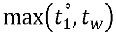
      t w , i charging = max t 1 ° t w
      Figure imgb0015
    • the allocable electricity quantity Q w t w , i charing
      Figure imgb0016
      of the charging pile jw in t 1 °
      Figure imgb0017
      is estimated according to the following equation set 10-2:
      { Q w t w , i charging = E t 1 ° + t 1 ° t w , i charging p stroage t × d t , when t 1 ° t w , i charging t rated Q w t w , i charging = E rated when t w , i charging > t rated
      Figure imgb0018
    • the constraint condition of the equation set 10-2 is as follows:
      0 E t 1 ° + t 1 ° t w , i charging p stroage t × d t E rated
      Figure imgb0019
    • the reserved allocable electricity quantity TPw of the charging pile jw in t 1 °
      Figure imgb0020
      is estimated according to the following equation set 10-3:
      TP w = min Q w t w , i charging , bat _ cap i RE i t w
      Figure imgb0021
    • the reserved charging duration T w , i charging
      Figure imgb0022
      of the electric vehicle i at the charging pile jw is estimated according to the following Equation 10-4:
      T w , i charging = TP w ÷ P w out
      Figure imgb0023
    • the remaining electric quantity of the reserved charging start time t w , i charging
      Figure imgb0024
      corresponding to the charging pile jw is E t w , i charging = Q w t w , i charging
      Figure imgb0025
      , the remaining electric quantity of the reserved charging end time ( t w , i charging + T w , i charging
      Figure imgb0026
      ) corresponding to the charging pile jw is E t w , i charging + T w , i charging
      Figure imgb0027
      = E t w , i charging TP w
      Figure imgb0028
      ;
    • the above variables in the equations in Step (10-1-3) are defined as follows: t w , i charging
      Figure imgb0029
      is the reserved charging start time of the electric vehicle i at the charging pile jw; tw is the estimated time when the electric vehicle i arrives at the charging pile j w; Q w t w , i charging
      Figure imgb0030
      is the allocable electricity quantity of the charging pile jw in t 1 °
      Figure imgb0031
      ; E t 1 °
      Figure imgb0032
      is the remaining electric quantity of the charging pile jw at the reserved charging end time t 1 °
      Figure imgb0033
      corresponding to the preceding vehicle i1; p storage(t) is the predicted energy storage power of the charging pile jw at the corresponding time t, which is predicted by the prior art method; P w out
      Figure imgb0034
      is a constant output power of the charging pile jw ; E rated is the rated electricity quantity of the energy storage battery of the charging pile jw ; t rated is the time when the energy storage of the charging pile jw reaches the rated electricity quantity E rated in t 1 °
      Figure imgb0035
      ; bat_capi is the rated electricity quantity of the power battery of the electric vehicle i, REi (tw ) is the estimated remaining electric quantity of the electric vehicle i at the time tw when the electric vehicle arrives at the charging pile jw ; TPw is the reserved allocated electricity quantity of the electric vehicle i in t 1 °
      Figure imgb0036
      of the charging pile jw ; T w , i charging
      Figure imgb0037
      is the reserved charging duration of the electric vehicle i at the charging pile jw ;
    • (10-1-4), if the idle period of the charging pile jw between tw and tw +σ is an allocable idle period and is finite, assuming that the preceding vehicle i 1 has reserved for charging at the charging pile jw in the period t 1 t 1 °
      Figure imgb0038
      , the reserved allocated electric quantity is TP 1 = E t 1 ° E t 1
      Figure imgb0039
      ; assuming that the preceding vehicle i 2 has reserved for charging at the charging pile jw in the period t 2 t 2 °
      Figure imgb0040
      , the reserved allocated electric quantity is TP 2 = E t 2 ° E t 2
      Figure imgb0041
      ; where t 1 and t 1 °
      Figure imgb0042
      correspond to the reserved charging start time and the reserved charging end time of the preceding vehicle i 1, respectively, t 2 and t 2 °
      Figure imgb0043
      correspond to the reserved charging start time and the reserved charging end time of the preceding vehicle i 2, respectively; t 1 < t 1 ° < t 2 < t 2 °
      Figure imgb0044
      ; E(t1), E t 1 °
      Figure imgb0045
      , E(t 2) and E t 2 °
      Figure imgb0046
      correspond to the estimated remaining electric quantity of the charging pile jw at the time t 1, t 1 ° ,
      Figure imgb0047
      , t 2 and t 2 °
      Figure imgb0048
      ; t 1 ° t 2
      Figure imgb0049
      is the allocable electricity quantity idle period, the precondition for the charging pile jw to allow the electric vehicle i to jump a queue to reserve for charging in the allocable electricity quantity idle period t 1 ° t 2
      Figure imgb0050
      is to not affect the reserved allocated electricity quantity and the reserved charging start and end time of other preceding vehicles that have already reserved for charging after this period t 1 ° t 2
      Figure imgb0051
      , that is, ensuring that the reserved allocated electricity quantity TP 2 of the preceding vehicle i 2 in the reserved charging period t 2 t 2 °
      Figure imgb0052
      remains unchanged first, that is, meeting the following Equation 10-5: TP 2 E t 1 ° + t 1 ° t w , i charging p storage t × d t P w out × t 3 ° t w , i charging + t 3 ° t 2 p storage t × d t
      Figure imgb0053
    • the constraint condition of Equation 10-5 is: { E t 1 ° + t 1 ° t w , i charging p storage t × d t P w out × t 3 ° t w , i charging + t 3 ° t 2 p storage t × d t E rated 0 E t 1 ° + t 1 ° t w , i charging p storage t × d t E rated P w out × t 3 ° t w , i charging E t 1 ° + t 1 ° t w , i charging p storage t × d t t 1 < t 1 ° t w , i charging < t 3 ° < t 2 < t 2 °
      Figure imgb0054
    • according to Equation 10-5 and its constraint condition, calculating the latest charging end time t 3 °
      Figure imgb0055
      of the electric vehicle i when the charging pile jw allows the electric vehicle i to jump a queue for charging, and estimating the allocable electric quantity Q w t w , i charging
      Figure imgb0056
      of the charging in pile jw in the allocable electric quantity idle period t 1 ° t 2
      Figure imgb0057
      according to the following equation set 10-6:
      { Q w t w , i charging = E t 1 ° + t 1 ° t w , i charging p storage t × d t , when t w , i charging < t rated Q w t w , i charging = E rated , when t rated t w , i charging < t 3 ° and t 3 ° t w , i charging > E rated P w out Q w t w , i charging = P w out × t 3 ° t w , i charging , when t rated t w , i charging < t 3 ° and t 3 ° t w , i charging E rated P w out
      Figure imgb0058
    • in the Equation 10-5 and Equation 10-6, estimating the reserved charging start time t w , i charging
      Figure imgb0059
      of the electric vehicle i at the charging pile jw according to the following Equation 10-7:
      t w , i charging = max t 1 ° t w
      Figure imgb0060
    • obtaining Q w t w , i charging
      Figure imgb0061
      according to Equation 10-6, and estimating the reserved allocated electric quantity TPw of the electric vehicle i at the charging pile jw according to the following Equation 10-8:
      TP w = min Q w t w , i charging , bat _ cap i RE i t w
      Figure imgb0062
    • obtaining TPw according to Equation 10-8, and estimating the reserved allocated charging duration T w , i charging
      Figure imgb0063
      of the electric vehicle i at the charging pile jw according to the following Equation 10-8:
      T w , i charging = TP w ÷ P w out
      Figure imgb0064
    • if there are other preceding vehicles that reserve for charging at the charging pile jw before the electric vehicle i, but the time for reserving for charging is after the period t 2 t 2 °
      Figure imgb0065
      of the preceding vehicle i 2 reserved for charging, the precondition for the charging pile jw to allow the electric vehicle i to jump a queue to reserve for charging in the allocable electricity quantity idle period t 1 ° t 2
      Figure imgb0066
      is that in addition to ensuring that the reserved allocated electricity quantity TP 2 of the preceding vehicle i 2 in the reserved charging period t 2 t 2 °
      Figure imgb0067
      remains unchanged, it is also necessary to ensure that the reserved start and end time and the reserved allocated electricity quantity of all other preceding vehicles remain unchanged, and the specific methods are as follows:
      assuming that there are other preceding vehicles i 4 that reserve for charging in the period t 4 t 4 °
      Figure imgb0068
      before the electric vehicle i, the reserved allocated electric quantity is TP 4, in which t 2 < t 2 ° < t 4 < t 4 °
      Figure imgb0069
      , TPw also meets the following Equation 10-10: TP 4 E t 1 ° + t 1 ° t w , i charging p storage t × d t TP w + t w , i charging + T w , i charging t 2 p storage t × d t TP 2 + t 2 ° t 4 p storage t × d t
      Figure imgb0070
    • if TPw does not meet Equation 10-10, TPw is reduced, and the corresponding T w , i charging
      Figure imgb0071
      is also reduced according to Equation 10-9 until Equation 10-10 is met;
    • if after the reserved charging period t 4 t 4 °
      Figure imgb0072
      of the preceding vehicle i 4, there are other preceding vehicles i 5, i 6... reserving for charging at the charging pile jw before the electric vehicle i, the preceding vehicles are processed according to the method of the preceding vehicle i4 respectively until TPw can ensure that the reserved start and end time and reserved allocated electric quantity of all other preceding vehicles remain unchanged; if TPw is reduced to the preset threshold value, but it is not ensured that the reserved start and end time and the reserved allocated electric quantity of all other preceding vehicles remain unchanged, and the charging pile jw does not allow the electric vehicle i to jump a queue for reserved charging in the idle period t 1 ° t 2
      Figure imgb0073
      , that is, assuming that the reserved allocated electric quantity is TPw =0;
    • if the final TPw ≠ 0, the remaining electric quantity of the charging pile jw corresponding to the reserved charging start time t w , i charging
      Figure imgb0074
      is E t w , i charging = E t 1 ° + t 1 ° t w , i charging p storage t × d t
      Figure imgb0075
      , and the remaining electric quantity of the charging pile jw corresponding to the reserved charging end time t w , i charging + T w , i charging
      Figure imgb0076
      is E t w , i charging + T w , i charging = E t w , i charging TP w
      Figure imgb0077
      ;
    • the above variables in the equations in Step (10-1-4) are defined as follows: TP 2 is the reserved allocated electricity quantity of the preceding vehicle i 2 in the reserved charging period t 2 t 2
      Figure imgb0078
      ; E t 1
      Figure imgb0079
      is the remaining electric quantity of the charging pile jw at the reserved charging end time t 1
      Figure imgb0080
      corresponding to the preceding vehicle i 1; p storage(t) is the predicted energy storage power of the charging pile jw at the corresponding time t, which is predicted by the prior art method; P w out
      Figure imgb0081
      is a constant output power of the charging pile jw ; t w , i charging
      Figure imgb0082
      is the reserved charging start time of the electric vehicle i at the charging pile jw ; tw is the estimated time when the electric vehicle i arrives at the charging pile jw ; E rated is the rated electricity quantity of the energy storage battery of the charging pile jw ; t 3
      Figure imgb0083
      is the latest charging end time of the electric vehicle i when the charging pile jw allows the electric vehicle i to jump a queue for charging, and Q w t w , i charging
      Figure imgb0084
      is the estimated allocable electric quantity of the charging in pile jw in t 1 t 2
      Figure imgb0085
      ; t rated is the time when the energy storage of the charging pile jw reaches the rated electricity quantity E rated in t 1
      Figure imgb0086
      ; bat_capi is the rated electricity quantity of the power battery of the electric vehicle i, REi (tw ) is the estimated remaining electric quantity of the electric vehicle i at the time tw when the electric vehicle arrives at the charging pile jw ; TPw is the reserved allocated electricity quantity of the electric vehicle i in t 1
      Figure imgb0087
      of the charging pile jw ; T w , i charging
      Figure imgb0088
      is the reserved charging duration of the electric vehicle i at the charging pile jw ; TP 4 is the reserved allocated electric quantity of the preceding vehicle i 4 in the period t 4 t 4
      Figure imgb0089
      .
  • The electric-quantity-based path planning method further includes Step (10-1-5), wherein every time a Δt time passes, the dispatching system platform executes from Step (10-1-2) to Step (10-1-4) according to the re-updated reserved service list of the charging pile jw , and re-estimates the reserved allocated electric quantity TPw.
  • The reserved allocated electric quantity of the electric vehicle at the charging pile jw is TPw, and when the charging pile jw is a power-grid direct-supply charging pile, the specific step of the method for estimating the reserved allocated electric quantity TPw is as follows:
    • (10-2-1), assuming that the electric vehicle is an electric vehicle i, setting a queuing time limit σ after the time tw when the electric vehicle i arrives at the charging pile jw first, where σ is a user-defined time value;
    • (10-2-2), according to a reserved service list of the charging pile jw , finding whether there is an idle period between the time tw and the time tw +σ when the electric vehicle i arrives at the charging pile jw ; wherein if there is no idle period, estimating the allocable electric quantity Qw (i) = 0 that the charging pile jw is capable of supplying to the electric vehicle i; that is, the reserved allocated electricity quantity TPw = 0 of the electric vehicle i at the charging pile jw ; if there is an idle period, proceeding to Step (10-2-3);
    • (10-2-3), if the idle period is infinite, the idle period is denoted as t 1
      Figure imgb0090
      , where t 1
      Figure imgb0091
      corresponds to the reserved charging end time of the preceding vehicle i 1 and there is no other preceding vehicle reserved for charging after t 1
      Figure imgb0092
      ; the reserved allocated electric quantity TPw of the electric vehicle i at the charging pile jw is estimated according to Equation 10-11:
      TP w = bat _ cap i RE i t w
      Figure imgb0093
    • in Equation 10-11, bat_capi is the rated electricity quantity of the power battery of the electric vehicle i, REi (tw ) is the estimated remaining electric quantity of the electric vehicle i at the time tw when the electric vehicle arrives at the charging pile jw ;
    • the reserved charging start time of the electric vehicle i at the charging pile jw is t w , i charging =
      Figure imgb0094
      max t 1 t w
      Figure imgb0095
      ; where tw is the estimated time when the electric vehicle i arrives at the charging pile jw ;
    • obtaining TPw according to Equation 10-11, and the reserved charging duration is T w , i charging =
      Figure imgb0096
      TP w ÷ P w out
      Figure imgb0097
      TPw where P w out
      Figure imgb0098
      is a constant output power of the charging pile jw ;
    • (10-2-4), if the idle period is finite, assuming that the preceding vehicle i 1 has reserved for charging at the charging pile jw in the period t 1 t 1
      Figure imgb0099
      ; there is a preceding vehicle i 2 that has reserved for charging at the charging pile jw in the period t 2 t 2
      Figure imgb0100
      ; where t 1 and t 1 °
      Figure imgb0101
      correspond to the reserved charging start time and the reserved charging end time of the preceding vehicle i 1 , respectively, t 2 and t 2 °
      Figure imgb0102
      correspond to the reserved charging start time and the reserved charging end time of the preceding vehicle i 2, respectively; t 1 < t 1 ° < t 2 < t 2 °
      Figure imgb0103
      ; and the reserved allocated electric quantity TPw of the electric vehicle i at the charging pile jw is estimated according to the following Equation 10-12:
      TP w = min bat _ cap i RE i t w , P w out × t 2 t w , i charging
      Figure imgb0104
    • in Equation 10-12, bat_capi is the rated electricity quantity of the power battery of the electric vehicle i, REi (tw ) is the estimated remaining electric quantity of the electric vehicle i at the time tw when the electric vehicle arrives at the charging pile jw ; P w out
      Figure imgb0105
      is a constant output power of the charging pile jw ; t w , i charging
      Figure imgb0106
      is the reserved charging in start time of the electric vehicle i at the charging pile jw, t w , i charging =
      Figure imgb0107
      max t 1 ° t w
      Figure imgb0108
      ;
    • the reserved charging duration of the electric vehicle i at the charging pile jw is T w , i charging = TP w ÷
      Figure imgb0109
      P w out
      Figure imgb0110
      .
  • The time tw when the electric vehicle arrives at the charging pile jw is replaced with tw - θ or tw + θ, where θ is a user-defined duration value.
  • The electric-quantity-based path planning method further includes a method for adjusting the preceding vehicle as follows:
    assuming that prior to the reservation of the electric vehicle i, the existing preceding vehicles reserve for charging and generate their own whole-journey reservation schemes, respectively; when the electric vehicle i reserves for charging according to the electric-quantity-based path planning method for the electric vehicle compatible with the energy storage charging pile, and when the shortest path lz in the selected path set L = {l 1···, la } from the departure place O to the destination D does not meet the whole-journey endurance requirement, adjusting the whole-journey reservation scheme of the preceding vehicle, including canceling or reducing the reserved allocated electric quantity of the preceding vehicle at one or more common piles, judging whether the shortest path lz of the electric vehicle i and the path of the original whole-journey reservation scheme of the preceding vehicle meet the whole-journey endurance requirements of the electric vehicle i and the preceding vehicle, respectively, wherein if so, the dispatching system platform generates a whole-journey reservation scheme for the electric vehicle i, and generates a new whole-journey reservation scheme for the preceding vehicle, and the adjustment is successful; if any of the vehicles does not meet the whole-journey endurance requirement, it is impossible to adjust the preceding vehicle and restore the original whole-journey reservation scheme of the preceding vehicle.
  • An electric quantity reserving method of an energy storage charging pile includes the following steps:
    1. (1) an energy storage charging pile establishes and stores a reserved service list of the pile, and the field contents of the reserved service list include an electric vehicle user name, an electric vehicle brand, an vehicle model, reserved charging start time and charging pile remaining electric quantity corresponding to the time, reserved charging end time and charging pile remaining electric quantity corresponding to the time, reserved allocated electric quantity, reserved charging duration, a type of the idle periods and corresponding allocable electricity quantity;
    2. (2) the energy storage charging pile announces the type of each idle period of the pile and the corresponding allocable electric quantity without affecting the period when the preceding vehicle has reserved for charging and the reserved allocable electric quantity;
    3. (3) a vehicle-mounted terminal of the electric vehicle is connected with the energy storage charging pile through a wireless network, the type of the idle period and the corresponding allocable electric quantity announced in Step (2) are obtained, and an electric vehicle user selects a suitable idle period as required to reserve for charging the energy storage charging pile through the vehicle-mounted terminal of the electric vehicle;
    4. (4) after the electric vehicle is reserved, the energy storage charging pile updates the reserved service list of the pile according to the reserved result of Step (3).
  • The energy storage charging pile announces the type of each idle period of the pile and the corresponding allocable electric quantity in Step (2), and the specific method is as follows:
    • the idle period is divided into two types: the energy storage period and the allocable electric quantity idle period of the energy storage charging pile jw ;
    • searching the reserved service list of the charging pile jw , assuming that vehicles have reserved for charging before and after the idle period t 1 ° t 2
      Figure imgb0111
      , if a preceding vehicle i 1 has reserved for charging in the period t 1 t 1 °
      Figure imgb0112
      , the reserved allocated electric quantity is TP 1 = E t 1 ° E t 1
      Figure imgb0113
      ; a preceding vehicle i 2 has reserved for charging in the period t 2 t 2 °
      Figure imgb0114
      , the reserved allocated electric quantity is TP 2 = E t 2 ° E t 2
      Figure imgb0115
      ; where t 1 and t 1 °
      Figure imgb0116
      correspond to the reserved charging start time and the reserved charging end time of the preceding vehicle i 1 respectively, and where t 2 and t 2 °
      Figure imgb0117
      correspond to the reserved charging start time and the reserved charging end time of the preceding vehicle i 2 respectively; t 1 < t 1 ° < t 2 < t 2 °
      Figure imgb0118
      ; E(t1 ), E t 1 °
      Figure imgb0119
      , E(t 2) and E t 2 °
      Figure imgb0120
      correspond to the estimated remaining electric quantity of the charging pile jw at the time t 1, t 1 °
      Figure imgb0121
      , t 2 and t 2 °
      Figure imgb0122
      ;
      1. (A) the types of the idle periods t 1 ° t 2
        Figure imgb0123
        are announced as follows:
        when the following Equation 9-1 is met, t 1 ° t 2
        Figure imgb0124
        is announced to be the energy storage period of the energy storage charging pile jw ;
        { 0 E t 2 E rated and E t 2 = TP 2 E t 2 = E t 1 ° + t 1 ° t 2 p storage t × d t t 1 < t 1 ° < t 2 < t 2 °
        Figure imgb0125
        • in Equation 9-1, E rated is the rated electricity quantity of the energy storage battery of the energy storage charging pile jw ; p storage(t) is the predicted energy storage power of the energy storage charging pile jw at the time t, which is predicted by the prior art method;
        • the energy storage period of the energy storage charging pile jw is only used for energy storage of this pile, that is, the corresponding allocable electricity quantity is 0;
      2. (B) the method for announcing the allocable electric quantity idle period of the energy storage charging pile jw is as follows:
        • after excluding the energy storage period of the energy storage charging pile jw announced in Step (A) from all the idle periods of the energy storage charging pile jw, the remaining periods are the allocable electricity quantity idle periods of the energy storage charging pile jw ;
        • dividing the allocable electric quantity idle period into time points according to a fixed duration ρ, where ρ is a user-defined constant, setting the idle period t 1 ° t 2
          Figure imgb0126
          as the allocable electric quantity idle period which can be divided into several time points t 1 ° , t 1 ° + ρ , t 1 ° + 2 × ρ , . t 1 ° + k × ρ , ( t 1 ° + k + 1 ×
          Figure imgb0127
          ρ), .....t 2, k = 0,1,2,3 ... ., 3k ∈ N, and setting the reserved charging start time of the electric vehicle in the allocable electric quantity idle period as the time point t 1 ° + k × ρ
          Figure imgb0128
          ; where the allocable electricity quantity idle period of the energy storage charging pile jw must meet the following Equation 9-2: TP 2 E t 1 ° + t 1 ° t 1 ° + k × ρ p storage t × d t P w out × t 3 ° t 1 ° + k × ρ _ t 3 ° t 2 p storage t × d t
          Figure imgb0129
    • the constraint condition of Equation 9-2 is: { 0 E t 2 ° E rated 0 E t 2 E rated 0 E t 1 ° + t 1 ° t 1 ° + k × ρ p storage t × d t E rated P w out × t 3 ° t 1 ° + k × ρ E t 1 ° + t 1 ° t 1 ° + k × ρ p storage t × d t t 1 < t 1 ° t 1 ° + k × ρ < t 3 ° < t 2 < t 2 °
      Figure imgb0130
    • in Equation 9-2 and its constraint conditions, p storage(t) is the predicted energy storage power of the energy storage charging pile jw at the time t, which is predicted by the prior art method; P w out
      Figure imgb0131
      is a constant output power of the charging pile jw ; E rated is the rated electricity quantity of the energy storage battery of the energy storage charging pile jw ; t 3
      Figure imgb0132
      is the latest charging end time for an electric vehicle;
    • the latest charging end time t 3
      Figure imgb0133
      of the electric vehicle can be obtained from Equation 9-2 and its constraint conditions, t 3 t 2
      Figure imgb0134
      is the energy storage period of the energy storage charging pile jw ;
    • the corresponding allocable electric quantity Qw (t) of the energy storage charging pile jw at the time point t 1 + k × ρ
      Figure imgb0135
      in the allocable electricity quantity idle period t 1 t 2
      Figure imgb0136
      is estimated according to the following equation set 9-3:
      { Q w t = E t 1 ° + t 1 ° t 1 ° + k × ρ p storage t × d t , when t 1 ° + k × ρ < t rated Q w t = E rated , when t rated t 1 ° + k × ρ < t 3 ° and t 3 ° t 1 ° + k × ρ > E rated P w out Q w t = P w out × t 3 ° t 1 ° + k × ρ , when t rated t 1 ° + k × ρ and t 3 ° t 1 ° + k × ρ E rated P w out
      Figure imgb0137
    • in equation set 9-3, k = 0,1,2,3 ...., ∃k ∈ N; t rated denotes the time when the energy storage of the energy storage charging pile jw reaches the rated electricity quantity, and the definitions of other variables are the same as Equation 9-2 and its constraints;
    • announcing the corresponding allocable electric quantity Qw (t) at the time point t 1 + k × ρ
      Figure imgb0138
      in the allocable electricity quantity idle period t 1 t 2
      Figure imgb0139
      in the reserved service list of the energy storage charging pile jw ; announcing the rest of the time points according to the time point t 1 + k × ρ
      Figure imgb0140
      .
  • The method for announcing the type of the idle period t 1 t 2
    Figure imgb0141
    further includes: every time a Δt time passes, the dispatching system platform re-estimates the comprehensive energy storage electricity quantity t 1 ° t 2 p storage t × d t
    Figure imgb0142
    of the charging pile jw in Equation 9-1, re-estimates and announces the electricity quantity according to Equation 9-1, and updates the reserved service list of the charging pile jw .
  • The method for announcing the allocable electricity quantity idle period of the energy storage charging pile jw further includes: every time a Δt time passes, the dispatching system platform re-estimates the comprehensive energy storage electricity quantity t 1 ° t 1 ° + k × ρ p storage t × d t
    Figure imgb0143
    and t 3 ° t 2 p storage t ×
    Figure imgb0144
    d(t) of the charging pile jw in Equation 9-2 and its constraint conditions, re-estimates and announces the electricity quantity according to Equation 9-3, and updates the reserved service list of the charging pile jw .
  • The present disclosure has the following beneficial effects.
    1. 1. The planning of the whole-journey electric-quantity-based path of the vehicle is realized, and the planned shortest feasible path meets the requirements of energy consumption saving, as well as the needs of users and low-carbon society.
    2. 2. Based on the energy storage prediction of the energy storage charging pile, the multi-user charging behavior of the energy storage charging pile and the discharging behavior of the energy storage charging pile are unified in the time dimension, and the multi-user reservation of the energy storage charging pile is realized.
    3. 3. The fused use of an energy storage charging pile and a power-grid direct-supply charging pile is realized using arrival time matching and energy time differentiation, which improves the integrity of the charging pile network and lays the foundation for fast charging network.
    4. 4. Charging scheduling is performed on the vehicle through the dispatching system platform. The original disorderly reservation specified by a user based on the pile position is upgraded to the unified planning and allocation by the scheduling platform based on the energy demand of the users in the whole network and the charging pile resources, and the users are subjected to mandatory scheduling, thus maximizing the resource utilization and meeting the driving needs of more vehicles.
    BRIEF DESCRIPTION OF THE DRAWINGS
    • FIG. 1 is a schematic diagram showing that the idle period of an energy storage charging pile is the energy storage period of the energy storage charging pile according to the method 9 in Embodiment 5 of the present disclosure. In the figure, a vertical axis E denotes the remaining electric quantity of the energy storage charging pile, and the horizontal axis t denotes the time; t 1 and t 1 °
      Figure imgb0145
      correspond to the reserved charging start time and the reserved charging end time of the preceding vehicle i 1 , respectively, t 2 and t 2 °
      Figure imgb0146
      correspond to the reserved charging start time and the reserved charging end time of the preceding vehicle i 2, respectively; TP 2 is the reserved allocated electric quantity of the preceding vehicle i 2 that has reserved for charging in the period t 2 t 2 °
      Figure imgb0147
      ; E rated is the rated electricity quantity of the energy storage battery of the energy storage pile; E(t 1), E t 1 °
      Figure imgb0148
      and E(t2 ) correspond to the remaing electric quantity of the energy storage charging pile jw at the time t 1 , t 1 °
      Figure imgb0149
      and t 2.
    • FIG. 2 is a schematic diagram of method 10 in Embodiment 2 of the present disclosure when the charging pile jw allows the electric vehicle i to jump a queue to reserve for charging in a finite allocable electricity quantity idle period t 1 ° t 2
      Figure imgb0150
      ; in the figure, a vertical axis E denotes the remaining electric quantity of the energy storage charging pile, and the horizontal axis t denotes the time; t 1 and t 1 °
      Figure imgb0151
      correspond to the reserved charging start time and the reserved charging end time of the preceding vehicle i 1 , respectively, t 2 and t 2 °
      Figure imgb0152
      correspond to the reserved charging start time and the reserved charging end time of the preceding vehicle i 2, respectively; tw is the estimated time when the electric vehicle i arrives at the charging pile jw, tw is the estimated time when the electric vehicle i arrives at the charging pile jw ; t 3 °
      Figure imgb0153
      is the latest charging end time of the electric vehicle i when the charging pile jw allows the electric vehicle i to jump a queue for charging, t 4 and t 4 °
      Figure imgb0154
      correspond to the reserved charging start time and the reserved charging end time of the preceding vehicle i 4 , respectively; E rated is the rated electricity quantity of the energy storage battery of the energy storage charging pile.
    DETAILED DESCRIPTION OF THE EMBODIMENTS
  • In the following, the technical scheme of the present disclosure will be described in detail with specific embodiments and attached drawings, which does not limit the protection scope of the claims of the present disclosure.
  • Before explaining specific embodiments, methods 1 to 10 involved in specific embodiments of the present disclosure will be explained as follows.
  • Method 1: Method for obtaining the path distance of segments:
  • According to the received position coordinates of the charging piles, the dispatching system platform obtains all the charging piles distributed along the path lz . Assuming that there are n charging piles, the directed sequence matrix of the n charging piles along the path lz from the departure place O is denoted as (j 1, j 2,··· jn ) T. (j 0 ,j 1, ..., j n+1) T is used to denote the segmented point directed sequence matrix of the path lz in which the departure place O, n charging piles distributed along the path and the destination D serve as the segmented points, where j 0 corresponds to the departure place O, and j n+1 corresponds to the destination D.
  • The dispatching system platform obtains the path distance j 0 ,i 1, ...,jn, j n+1) T between two adjacent segmented points from the existing map respectively. The obtained segmented path distance is denoted by the directed sequence matrix (dist 0,1 , dist 1,2 ,··· dist n-1 ,n,dist n,n+1) T , where disto,l denotes the path distance from the departure place O to the first charging pile j 1, dist 1,2 denotes the path distance from the first charging pile j 1 to the second charging pile j 2 , and so on, dist n,n+1 denotes the path distance from the n-th charging pile jn to the destination D.
  • Method 2: Method for estimating the driving time of the segmented path of the electric vehicle i:
  • According to Equation 2-1, the driving time t w-1,w of the segmented path of the electric vehicle i is estimated:
    t w 1 , w = dist w 1 , w v w , w 1 , n + 1
    Figure imgb0155
  • In Equation 2-1, dist w-1,w denotes the path distance from the segmented point j w-1 to the segmented point jw obtained by the method 1. vw denotes the average speed of the electric vehicle i from the segmented point j w-1 to the segmented point jw, vw can be the average speed of the electric vehicle i passing through dist w-1,w in the historical statistical period extracted from traffic historical big data, or the average speed of all vehicles passing through dist w-1,w in the historical statistical period extracted from traffic historical big data, and the value of the historical statistical period is user-defined.
  • The driving time t w-1,w of the electric vehicle i can also be obtained directly from the existing GIS map.
  • Method 3: One of the following two methods can be selected to estimate the energy consumption of the segmented path of the electric vehicle i:
  • Method A: the segmented path energy consumption of the electric vehicle i according to the following Equation 3-1:
    EC w 1 , w = Aver × dist w 1 , w , w 1 , n + 1
    Figure imgb0156
  • In Equation 3-1, EC w-1,w denotes the estimated energy consumption of the electric vehicle i from the segmented point j w-1 to the segmented point jw, and the segmented points j w-1 and the segmented point jw are obtained by the method 1. dist w-1,w is defined as in Equation 2-1. Aver is the power consumption per unit mileage of the electric vehicle i.
  • The power consumption per unit mileage Aver is calculated according to Equation 3-2:
    Aver = m vehicle + m negative φ
    Figure imgb0157
  • In Equation 3-2, m vehicle is the body mass of the electric vehicle i, and m negative is the on-board mass of the electric vehicle i. If the vehicle type of the electric vehicle i is not a vehicle type reserved for the first time on the dispatching system platform, ϕ is the historical specific energy consumption coefficient of the electric vehicle i extracted from traffic historical big data by the dispatching system platform; if it is a vehicle type reserved for the first time, the specific energy consumption coefficient ϕ is calculated according to Equation 3-3.
    φ = bat _ cap i m vehicle × S max
    Figure imgb0158
  • In Equation 3-3, Smax is the maximum endurance mileage of the model of the electric vehicle i provided by the manufacturer, bat_capi is the rated capacity of the power battery of the electric vehicle i, and m vehicle is defined as in Equation 3-2.
  • Method B: the segmented path energy consumption EC w-1,w of the electric vehicle i according to the following Equation 3-4:
    EC w 1 , w = dist w 1 , w × kWh w 1 , n + 1
    Figure imgb0159
  • In Equation 3-4, EC w-1,w is defined as in Equation 3-1, dist w-1,w is defined as in Equation 2-1, and kWh is the power consumption per 100 kilometers of the electric vehicle i, which can be obtained from factory parameters or from traffic history big data.
  • Method 4: The charging duration T w , i charging
    Figure imgb0160
    of the electric vehicle i at the charging pile jw is estimate according to the following Equation 4-1:
  • In Equation 4-1, P w out
    Figure imgb0161
    denotes the constant output power of the charging pile jw , and TPw is the reserved allocated electric quantity of the electric vehicle i at the charging pile jw estimated by the method 10.
  • Method 5: The queuing charging duration T w , i queuing
    Figure imgb0162
    of the electric vehicle i at the charging pile jw is estimated according to the following Equation 5-1:
    T w , i queuing = t w , i charging t w
    Figure imgb0163
  • In Equation 5-1, t w , i charging
    Figure imgb0164
    is the reserved charging start time estimated by the method 10, tw is the time when the electric vehicle i arrives at the charging pile jw which is estimated by the method 6.
  • Method 6: The time tw when the electric vehicle i arrives at the charging pile jw is estimated according to the following Equation 6-1:
  • t w = t 0 + the sum of the pre-reserved charging duration + the sum of the pre-queuing charging duration + t 0 , w w 1 n
    Figure imgb0165
  • in Equation 6-1, t 0 denotes the departure time of the electric vehicle i; t 0,w denotes the driving duration of the electric vehicle i along the path lz from the departure place O to the charging pile iw ; t 0,w is obtained by estimating the driving time of each segmented path along the path lz from the departure place O to the charging pile jw by the method 2 and then accumulating the driving time; the sum of the pre-reserved charging duration refers to the sum of the reserved charging duration that has reserved for charging at other charging piles along the path when the electric vehicle i arrives at the charging pile jw along the path lz from the departure place O, and the charging durations of other charging piles along the path are obtained by the method 4, respectively; the sum of the pre-queuing charging duration refers to the sum of the queuing charging duration that has reserved for charging at other charging piles along the path when the electric vehicle i arrives at the charging pile jw along the path lz from the departure place O, and the queuing charging durations of other charging piles along the path are obtained by the method 5, respectively
  • Method 7: The remaining electric quantity REi (tw ) of the electric vehicle i at the time tw when the electric vehicle arrives at the charging pile jw is estimated according to the following Equation 7-1:
  • RE i t w = bat _ cap str + the sum of the pre-reserved allocated electric quantity EC 0 , w w 1 n
    Figure imgb0166
  • in Equation 7-1, bat_capstr is an initial remaining electric quantity when the electric vehicle i departs; the sum of the pre-reserved allocated electric quantity refers to the sum of the electric quantity that has reserved for allocation at other charging piles along the path when the electric vehicle i arrives at the charging pile jw from the departure place O along the path lz , and the reserved allocated electric quantity at other charging piles along the path is estimated by the method 10, respectively; EC 0,w indicates the energy consumption of the electric vehicle i driving along the path lz from the departure place O to the charging pile jw, and EC0,w is obtained by estimating the segmented path energy consumption of the electric vehicle i by the method 3 and then accumulating the energy consumption.
  • Method 8: The comprehensive energy storage electricity quantity E(t 2 - t 1) of the charging pile jw is estimated:
  • If the charging pile of the present disclosure is an energy storage charging pile, the power supply source of the energy storage charging pile is new energy power generation, including one or more of solar power generation and wind power generation, and may also include complementary energy storage for purchasing electricity from the power grid.
  • The comprehensive energy storage electricity quantity E(t 2 - t 1) of the charging pile jw is denoted by the following Equation 8-1:
    E t 2 t 1 = t 1 t 2 p storage t × d t
    Figure imgb0167
  • The constraint condition of Equation 8-1 is: (t 2 - t 1) ≤ E rated; where E rated is the rated electricity quantity of the energy storage battery of the charging pile jw ; t 1 is the energy storage start time; t 2 is the energy storage end time; p storage(t) is the predicted energy storage power of the energy storage charging pile jw at the time t; if the power supply source of the energy storage charging pile is solar power generation, p storage(t) is the predicted output power of solar power generation at the time t, which is predicted by the prior art method; if the power supply source of the energy storage charging pile is wind power generation, p storage(t) is the predicted output power of wind power generation at the time t, which is predicted by the prior art method; if the power supply source of the energy storage charging pile is complementary energy storage for purchasing electricity from the power grid, p storage(t) is the constant output power of the power grid; if the power supply source of the energy storage charging pile is the combined power generation of multiple power supply sources from solar power generation, wind power generation or complementary energy storage for purchasing electricity from the power grid, p storage(t) is the output power of the combined power generation.
  • Because solar energy or wind power generation is closely related to weather, illumination and other factors, in order to improve the accuracy of estimation, every time a Δt time passes, the dispatching system platform re-estimates the comprehensive energy storage electricity quantity E(t2 - t 1) of the charging pile j w.
  • Method 9: The method for announcing the type of the idle period of the charging pile jw and the corresponding allocable electric quantity has the following steps:
    • (9.1) The energy storage charging pile jw establishes and stores a reserved service list, and the field contents of the reserved service list include an electric vehicle user name, an electric vehicle brand, an vehicle model, reserved charging start time and charging pile remaining electric quantity corresponding to the time, reserved charging end time and charging pile remaining electric quantity corresponding to the time, reserved allocated electric quantity, charging duration, a type of the idle periods and corresponding allocable electricity quantity.
    • (9.2) the idle period is divided into two types: the energy storage period and the allocable electric quantity idle period of the energy storage charging pile jw. The type of the idle period and the corresponding allocable electric quantity are announced according to Step (9.3) or Step (9.4), respectively.
  • The energy storage period of the energy storage charging pile jw means that in order not to affect the charging amount of other vehicles that have reserved for charging after the energy storage period and the reserved charging start and end time, the electric vehicle charging cannot be arranged only as the energy storage period of this pile in the idle period, and the energy storage period of the energy storage charging pile jw includes the energy storage start time and the energy storage end time;
  • The allocable electricity quantity idle period is the remaining idle period of the energy storage charging pile jw after excluding the energy storage period from all idle periods in the reserved service list, including the charging start time and the charging end time of the electric vehicle in the allocable electricity quantity idle period;
  • (9.3) The method for announcing the energy storage period of the energy storage charging pile jw is as follows:
  • The reserved service list of the charging pile jw is searched for the idle period, as shown in FIG. 1. If vehicles have reserved for charging before and after the idle period t 1 ° t 2
    Figure imgb0168
    , if a preceding vehicle i 1 has reserved for charging in the period t 1 t 1 °
    Figure imgb0169
    , the reserved allocated electric quantity is TP 1; a preceding vehicle i 2 has reserved for charging in the period t 2 t 2 °
    Figure imgb0170
    , the reserved allocated electric quantity is TP 2; where t 1 and t 1 °
    Figure imgb0171
    correspond to the reserved charging start time and the reserved charging end time of the preceding vehicle i 1 respectively, and where t 2 and t 2 °
    Figure imgb0172
    correspond to the reserved charging start time and the reserved charging end time of the preceding vehicle i 2 respectively; t 1 < t 1 ° < t 2 < t 2 °
    Figure imgb0173
    . E(t 1), E t 1 °
    Figure imgb0174
    , E(t 2) and E t 2 °
    Figure imgb0175
    correspond to the estimated remaining electric quantity of the charging pile jw at the time t 1 , t 1 °
    Figure imgb0176
    , t 2 and t 2 °
    Figure imgb0177
    . When the following Equation 9-1 is met, t 1 ° t 2
    Figure imgb0178
    is announced to be the energy storage period of the energy storage charging pile jw . No vehicle can be reserved for charging or be charged in this energy storage period. At this time, t 1 °
    Figure imgb0179
    is the energy storage start time of the energy storage charging pile jw , and t2 is the energy storage end time of the energy storage charging pile jw.
    { 0 E t 2 E rated and E t 2 = TP 2 E t 2 = E t 1 ° + t 1 ° t 2 p storage t × d t t 1 < t 1 ° < t 2 < t 2 °
    Figure imgb0180

    in Equation 9-1, E rated is the rated electricity quantity of the energy storage battery of the energy storage charging pile jw ; p storage(t) is the predicted energy storage power of the energy storage charging pile jw at the time t, which is predicted by the prior art method as in the method 8.
  • Every time a Δt time passes, the dispatching system platform re-estimates the comprehensive energy storage electricity quantity t 1 ° t 2 p storage t × d t
    Figure imgb0181
    of the charging pile jw in Equation 9-1, re-estimates and announces the electricity quantity according to Equation 9-1, and updates the reserved service list of the charging pile jw .
  • (9.4) The method for announcing the allocable electric quantity idle period of the energy storage charging pile jw includes the following steps.
  • First, all the idle periods in the reserved service list of the energy storage charging pile jw are searched for, and after excluding the energy storage period announced in Step (9.3), the remaining periods are the allocable electricity quantity idle periods.
  • Second, the allocable electric quantity idle period is divided into time points according to a fixed duration ρ, where ρ is a user-defined constant. If there is an allocable electric quantity idle period is 9: 00-10: 15 and ρ is user-defined for 30 minutes, the period can be divided into four time points, namely 9: 00, 9: 30, 10: 00 and 10: 15. The latest charging end time of the electric vehicle at each time point and the allocable electric quantity can be announced respectively. The announcing method is as follows.
  • The allocable electric quantity idle period is set as t 1 ° t 2
    Figure imgb0182
    , which can be divided into several time points t 1 ° , t 1 ° + ρ , t 1 ° + 2 × ρ , . t 1 ° + k × ρ , t 1 ° + k + 1 × ρ , .. t 2
    Figure imgb0183
    , k = 0,1,2,3 .... , ∃k ∈ N, and the reserved charging start time of the electric vehicle in the allocable electric quantity idle period is set as the time point t 1 ° + k × ρ
    Figure imgb0184
    . Assuming that vehicles have reserved for charging before and after the allocable electric quantity idle period t 1 ° t 2
    Figure imgb0185
    , if a preceding vehicle i 1 has reserved for charging in the period t 1 t 1 °
    Figure imgb0186
    , the reserved allocated electric quantity is TP 1 = E t 1 ° E t 1
    Figure imgb0187
    ; if other preceding vehicles i 2 have reserved for charging in the period t 2 t 2 °
    Figure imgb0188
    , the reserved allocated electric quantity is TP 2 = E t 2 ° E t 2
    Figure imgb0189
    ; where t 1 and t 1 °
    Figure imgb0190
    correspond to the reserved charging start time and the reserved charging end time of the preceding vehicle i 1 respectively, and where t 2 and t 2 °
    Figure imgb0191
    correspond to the reserved charging start time and the reserved charging end time of other preceding vehicles i 2 respectively; t 1 < t 1 ° < t 2 < t 2 °
    Figure imgb0192
    ; E t 1 ° , E t 2
    Figure imgb0193
    and E t 2 °
    Figure imgb0194
    correspond to the estimated remaining electric quantity of the charging pile jw at the time t1, t 1 °
    Figure imgb0195
    , t 2 and t 2 °
    Figure imgb0196
    . The allocable electricity quantity idle period of the energy storage charging pile jw must meet the following Equation 9-2: TP 2 E t 1 ° + t 1 ° t 1 ° + k × ρ p storage t × d t P w out × t 3 ° t 1 ° + k × ρ + t 3 ° t 2 p storage t × d t
    Figure imgb0197
  • The constraint condition of Equation 9-2 is: { 0 E t 2 ° E rated 0 E t 2 E rated 0 E t 1 ° + t 1 ° t 1 ° + k × ρ p storage t × d t E rated P w out × t 3 ° t 1 ° + k × ρ E t 1 ° + t 1 ° t 1 ° + k × ρ p storage t × d t t 1 < t 1 ° t 1 ° + k × ρ < t 3 ° < t 2 < t 2 °
    Figure imgb0198
  • In Equation 9-2 and its constraint conditions, p storage(t) is the predicted energy storage power of the energy storage charging pile jw at the time t, which is predicted by the prior art method as in the method 8; P w out
    Figure imgb0199
    is a constant output power of the charging pile jw ; E rated is the rated electricity quantity of the energy storage battery of the energy storage charging pile jw .
  • The latest charging end time t 3 °
    Figure imgb0200
    of the electric vehicle can be obtained from Equation 9-2 and its constraint conditions, t 3 ° t 2
    Figure imgb0201
    is the energy storage period of the energy storage charging pile jw .
  • The corresponding allocable electric quantity Qw (t) of the energy storage charging pile jw at the time point t 1 ° + k × ρ
    Figure imgb0202
    in the allocable electricity quantity idle period t 1 ° t 2
    Figure imgb0203
    is estimated according to the following equation set 9-3:
    { Q w t = E t 1 ° + t 1 ° t 1 ° + k × ρ p storage t × d t , when t 1 ° + k × ρ < t rated Q w t = E rated , when t rated t 1 ° + k × ρ < t 3 ° and t 3 ° t 1 ° + k × ρ > E rated P w out Q w t = P w out × t 3 ° t 1 ° + k × ρ , when t rated t 1 ° + k × ρ and t 3 ° t 1 ° + k × ρ E rated P w out
    Figure imgb0204
  • In equation set 9-3, k = 0,1,2,3 ...., ∃k ∈ N; t rated denotes the time when the energy storage of the energy storage charging pile jw reaches the rated electricity quantity, and the definitions of other variables are the same as Equation 9-2 and its constraints.
  • The corresponding allocable electric quantity Qw (t) at the time point t 1 ° + k × ρ
    Figure imgb0205
    in the allocable electricity quantity idle period t 1 ° t 2
    Figure imgb0206
    is announced in the reserved service list of the energy storage charging pile jw . The rest of the time points are announced according to the method announced at the time point t 1 ° + k × ρ
    Figure imgb0207
    .
  • Every time a Δt time passes, the dispatching system platform re-estimates the comprehensive energy storage electricity quantity t 1 ° t 1 ° + k × ρ p storage t × d t
    Figure imgb0208
    and t 3 ° t 2 p storage t × d t
    Figure imgb0209
    of the charging pile jw in Equation 9-2, re-estimates and announces the electricity quantity according to Equation 9-2 and its constraint conditions, and Equation 9-3, and updates the reserved service list of the charging pile jw .
  • Method 10: The allocable electric quantity Qw (i) that the charging pile jw can supply to the electric vehicle i, the reserved charging start time t w , i charging
    Figure imgb0210
    of the electric vehicle i at the charging pile jw , the reserved charging duration T w , i charging
    Figure imgb0211
    of the electric vehicle i at the charging pile jw, and the reserved allocable electricity quantity TPw of the electric vehicle i at the charging pile jw are estimated, respectively:
  • Estimation method 1: when the charging pile jw is an energy storage charging pile, the specific steps of the estimation method are as follows.
    • (10-1-1), a queuing time limit σ after the time tw when the electric vehicle i arrives at the charging pile jw is set first, where σ is a user-defined time value.
    • (10-1-2), the reserved service list of the charging pile jw is searched for the idle period of the charging pile jw between tw and tw +σ. According to the types of the idle periods announced in the Method 9, if all the found types of the idle periods are energy storage periods, the allocable electricity quantity that the charging pile jw can supply to the electric vehicle i is Qw (i)=0. The charging pile jw is incapable of reserving for charging the electric vehicle i, that is, the reserved allocated electricity quantity TPw = 0; if the found idle period type is an allocable electricity quantity idle period, proceed to Step (10-1-3).
    • (10-1-3), the reserved service list of the charging pile jw is searched for the allocable electricity quantity idle period. Assuming that the preceding vehicle i 1 has reserved for charging in a period t 1 t 1 °
      Figure imgb0212
      before the allocable electricity quantity idle period, where t 1 and t 1 °
      Figure imgb0213
      correspond to the reserved charging start time and the reserved charging end time of the preceding vehicle i 1 respectively, E(t 1) and E t 1 °
      Figure imgb0214
      correspond to the remaining electric quantity of the charging pile j w at the time t 1 and t 1 °
      Figure imgb0215
      , and the reserved allocated electric quantity of the preceding vehicle i 1 is TP 1 = E t 1 E t 1
      Figure imgb0216
      . There is no vehicle reserving for charging after t 1 °
      Figure imgb0217
      , that is, the allocable electricity quantity idle period is infinite, which is denoted as t 1 °
      Figure imgb0218
      . If the allocable electricity quantity idle period is not infinite, proceed to Step (10-1-4).
  • The reserved charging start time t w , i charging
    Figure imgb0219
    of the electric vehicle i at the charging pile j w is estimated according to the following Equation 10-1:
    t w , i charging = max t 1 ° t w
    Figure imgb0220
  • The allocable electricity quantity Q w t w , i charing
    Figure imgb0221
    of the charging pile j w in the allocable electricity quantity idle period t 1
    Figure imgb0222
    is estimated according to the following equation set 10-2:
    { Q w t w , i charging = E t 1 ° + t 1 ° t w , i charging p stroage t × d t , when t 1 ° t w , i charging t rated Q w t w , i charging = E rated when t w , i charging > t rated
    Figure imgb0223
  • The constraint condition of the equation set 10-2 is as follows:
    0 E t 1 ° + t 1 ° t w , i charging p stroage t × d t E rated
    Figure imgb0224
  • The reserved allocable electricity quantity TPw of the charging pile jw in the period t 1
    Figure imgb0225
    is estimated according to the following equation set 10-3:
    TP w = min Q w t w , i charging , bat _ cap i RE i t w
    Figure imgb0226
  • The reserved charging duration T w , i charging
    Figure imgb0227
    of the electric vehicle i at the charging pile jw is estimated according to the following Equation 10-4: T w , i charging = TP w ÷ P w out
    Figure imgb0228
  • The remaining electric quantity of the reserved charging start time t w , i charging
    Figure imgb0229
    corresponding to the charging pile jw is E t w , i charging = Q w t w , i charging
    Figure imgb0230
    , the remaining electric quantity of the reserved charging end time t w , i charging + T w , i charging
    Figure imgb0231
    corresponding to the charging pile jw is E t w , i charging + T w , i charging
    Figure imgb0232
    = E t w , i charging TP w
    Figure imgb0233
    .
  • The above variables in the equations in Step (10-1-3) are defined as follows: t w , i charging
    Figure imgb0234
    is the reserved charging start time of the electric vehicle i at the charging pile jw ; tw is the estimated time when the electric vehicle i arrives at the charging pile j w; Q w t w , i charging
    Figure imgb0235
    is the estimated allocable electricity quantity of the charging pile j w in [ t 1 ° , ) ; E t 1 °
    Figure imgb0236
    is the estimated remaining electric quantity of the charging pile jw at the reserved charging end time t 1 °
    Figure imgb0237
    corresponding to the preceding vehicle i 1; p storage(t) is the predicted energy storage power of the charging pile jw at the corresponding time t, which is predicted by the prior art method as in the method 8; t 1 ° t 1 ° + k × ρ p storage t × d t
    Figure imgb0238
    is the predicted comprehensive energy storage electricity quantity of the charging pile jw at the period t 1 ° , t w , i charging
    Figure imgb0239
    as in the method 8; P w out
    Figure imgb0240
    is a constant output power of the charging pile jw; E rated is the rated electricity quantity of the energy storage battery of the charging pile jw ; t rated is the time when the energy storage of the charging pile jw reaches the rated electricity quantity E rated in t 1 °
    Figure imgb0241
    ; bat_capi is the rated electricity quantity of the power battery of the electric vehicle i, REi (tw ) is the estimated remaining electric quantity of the electric vehicle i at the time tw when the electric vehicle arrives at the charging pile jw; TPw is the reserved allocated electricity quantity of the electric vehicle i in t 1 °
    Figure imgb0242
    of the charging pile jw ; T w , i charging
    Figure imgb0243
    is the reserved charging duration of the electric vehicle i at the charging pile jw .
  • (10-1-4), as shown in FIG. 2, assuming that the preceding vehicle i 1 has reserved for charging at the charging pile jw in the period t 1 t 1 °
    Figure imgb0244
    , the reserved allocated electric quantity is TP1; assuming that the preceding vehicle i2 has reserved for charging at the charging pile jw in the period t 2 t 2 °
    Figure imgb0245
    , the reserved allocated electric quantity is TP2; where t 1 and t 1 °
    Figure imgb0246
    correspond to the reserved charging start time and the reserved charging end time of the preceding vehicle i 1, respectively, t 2 and t 2 °
    Figure imgb0247
    correspond to the reserved charging start time and the reserved charging end time of the preceding vehicle i 2 , respectively; t 1 < t 1 ° <
    Figure imgb0248
    t 2 < t 2 °
    Figure imgb0249
    ; E(t 1), E t 1 °
    Figure imgb0250
    , E(t 2) and E t 2 °
    Figure imgb0251
    correspond to the estimated remaining electric quantity of the charging pile jw at the time t1, t 1 °
    Figure imgb0252
    , t 2 and t 2 °
    Figure imgb0253
    , which are obtained by searching the reserved service list of the charging pile jw . The precondition for the charging pile jw to allow the electric vehicle i to jump a queue to reserve for charging in the allocable electricity quantity idle period t 1 ° t 2
    Figure imgb0254
    is to not affect the reserved allocated electricity quantity and the reserved charging start and end time of other preceding vehicles that have already reserved for charging after this period t 1 ° t 2
    Figure imgb0255
    , as shown in the method 9, that is, the charging and discharging of the charging pile jw in the reserved charging period t 2 t 2 °
    Figure imgb0256
    must first meet the following Equation 10-5: TP 2 E t 1 ° + t 1 ° t w , i charging p storage t × d t P w out × t 3 ° t w , i charging + t 3 ° t 2 p storage t × d t
    Figure imgb0257
  • The constraint condition of Equation 10-5 is: { E t 1 ° + t 1 ° t w , i charging p storage t × d t P w out × t 3 ° t w , i charging + t 3 ° t 2 p storage t × d t E rated 0 E t 1 ° + t 1 ° t w , i charging p stoarage t × d t E rated p w out × t 3 ° t w , i charging E t 1 ° + t 1 ° t w , i charging p storage t × d t t 1 < t 1 ° t w , i charging < t 3 ° < t 2 < t 2 °
    Figure imgb0258
  • According to Equation 10-5 and its constraint condition, the latest charging end time t 3 °
    Figure imgb0259
    of the electric vehicle i can be calculate when the charging pile jw allows the electric vehicle i to jump a queue for charging in the reserved charging period t 1 ° t 2
    Figure imgb0260
    .
  • The allocable electric quantity Q w t w , i charging
    Figure imgb0261
    of the charging pile jw in the allocable electric quantity idle period t 1 ° t 2
    Figure imgb0262
    is estimated according to the following equation set 10-6:
    { Q w t w , i charging = E t 1 ° + t 1 ° t w , i charging p storage t × d t , when t w , i charging < t rated Q w t w , i charging = E rated , when t rated t w , i charging < t 3 ° and t 3 ° t w , i charging > E rated P w out Q w t w , i charging = P w out × t 3 ° t w , i charging , when t rated t w , i charging < t 3 ° and t 3 ° t w , i charging E rated P w out
    Figure imgb0263
  • In the Equation 10-5 and Equation 10-6, estimating the reserved charging start time t w , i charging
    Figure imgb0264
    of the electric vehicle i at the charging pile jw according to the following Equation 10-7: t w , i charging = max t 1 ° t w
    Figure imgb0265
    Q w t w , i charging
    Figure imgb0266
    is obtained according to Equation 10-6, and the reserved allocated electric quantity TPw of the electric vehicle i at the charging pile jw is estimated according to the following Equation 10-8: TP w = min Q w t w , i charging , bat _ cap i RE i t w
    Figure imgb0267
  • TPw is obtained according to Equation 10-8, and the reserved allocated charging duration T w , i charging
    Figure imgb0268
    of the electric vehicle i at the charging pile jw is estimated according to the following Equation 10-8: t w , i charging = TP w ÷ P w out
    Figure imgb0269
  • If there are other preceding vehicles that reserve for charging at the charging pile jw before the electric vehicle i, but the time for reserving for charging is after the period t 2 t 2 °
    Figure imgb0270
    of the preceding vehicle i 2 reserved for charging, the condition for the charging pile j w to allow the electric vehicle i to jump a queue to reserve for charging in the allocable electricity quantity idle period t 1 ° t 2
    Figure imgb0271
    is that in addition to ensuring that the reserved allocated electricity quantity TP 2 of the preceding vehicle i 2 in the reserved charging period t 2 t 2 °
    Figure imgb0272
    remains unchanged, it is also necessary to ensure that the reserved start and end time and the reserved allocated electricity quantity of all other preceding vehicles remain unchanged, and the specific methods are as follows.
  • Assuming that there are other preceding vehicles i 4 that reserve for charging in the period t 4 t 4 °
    Figure imgb0273
    before the electric vehicle i, t 4 and t 4 °
    Figure imgb0274
    correspond to the reserved charging start time and the reserved charging end time of the preceding vehicle i 4, respectively. The reserved allocated electric quantity is TP4, in which t 2 < t 2 ° < t 4 < t 4 °
    Figure imgb0275
    , TPw also meets the following Equation 10-10: TP 4 E t 1 ° + t 1 ° t w , i charging p storage t × d t TP w + t w , i charging + T w , i charging t 2 p storage t × d t TP 2 + t 2 ° t 4 p storage t × d t
    Figure imgb0276
  • If TPw does not meet Equation 10-10, TPw is reduced, and the corresponding T w , i charging
    Figure imgb0277
    is also reduced according to Equation 10-9 but t w , i charging
    Figure imgb0278
    remains unchanged until Equation 10-10 is met.
  • If after the reserved charging period t 4 t 4 °
    Figure imgb0279
    of the preceding vehicle i 4, there are other preceding vehicles i 5, i 6... reserving for charging at the charging pile jw before the electric vehicle i, the preceding vehicles are processed according to the method of the preceding vehicle i 4 respectively until TPw can ensure that the reserved allocated electric quantity of all other preceding vehicles i 2 , i 4, i 5, i 6 ...... remain unchanged. If TPw is reduced to the preset threshold value, but it is not ensured that the reserved allocated electric quantity of all other preceding vehicles remain unchanged, and the charging pile jw does not allow the electric vehicle i to jump a queue for reserved charging in the idle period t 1 ° t 2
    Figure imgb0280
    , that is, assuming that the reserved allocated electric quantity is TPw =0.
  • If the final TPw ≠ 0, the remaining electric quantity of the charging pile jw corresponding to the reserved charging start time t w , i charging
    Figure imgb0281
    is E t w , i charging = E t 1 ° + t 1 ° t w , i charging p storage t × d t
    Figure imgb0282
    , and the remaining electric quantity of the charging pile jw corresponding to the reserved charging end time t w , i charging + T w , i charging
    Figure imgb0283
    is E t w , i charging + T w , i charging = E t w , i charging TP w
    Figure imgb0284
    .
  • The above variables in the equations in Step (10-1-4) are defined as follows: TP 2 is the reserved allocated electricity quantity of the preceding vehicle i 2 in the reserved charging period t 2 t 2 °
    Figure imgb0285
    ; E t 1 °
    Figure imgb0286
    is the remaining electric quantity of the charging pile jw at the reserved charging end time t 1 °
    Figure imgb0287
    corresponding to the preceding vehicle i 1; p storage(t) is the predicted energy storage power of the charging pile jw at the corresponding time t, which is predicted by the prior art method; P w out
    Figure imgb0288
    is a constant output power of the charging pile jw ; t w , i charging
    Figure imgb0289
    is the reserved charging start time of the electric vehicle i at the charging pile jw ; tw is the estimated time when the electric vehicle i arrives at the charging pile j w; E rated is the rated electricity quantity of the energy storage battery of the charging pile jw; t 3 °
    Figure imgb0290
    is the latest charging end time of the electric vehicle i when the charging pile jw allows the electric vehicle i to jump a queue for charging, and Q w t w , i charging
    Figure imgb0291
    is the estimated allocable electric quantity of the charging pile jw in t 1 ° t 2
    Figure imgb0292
    ; t rated is the time when the energy storage of the charging pile jw reaches the rated electricity quantity E rated in [ t 1 ° , )
    Figure imgb0293
    ; bat_capi is the rated electricity quantity of the power battery of the electric vehicle i, REi (tw ) is the estimated remaining electric quantity of the electric vehicle i at the time tw when the electric vehicle arrives at the charging pile jw ; TPw is the reserved allocated electricity quantity of the electric vehicle i in [ t 1 ° , )
    Figure imgb0294
    of the charging pile jw ; T w , i charging
    Figure imgb0295
    is the reserved charging duration of the electric vehicle i at the charging pile jw; TP 4 is the reserved allocated electric quantity of the preceding vehicle i 4 in the period t 4 t 4 °
    Figure imgb0296
    .
  • (10-1-5), every time a Δt time passes, the dispatching system platform executes from Step (10-1-2) to Step (10-1-4) according to the re-updated reserved service list of the charging pile jw , and re-estimates the reserved allocated electric quantity TPw.
  • Estimation method 2: when the charging pile jw is a power-grid direct-supply charging pile, the specific estimation method is as follows.
    • (10-2-1), a queuing time limit σ after the time tw when the electric vehicle i arrives at the charging pile jw is set first, where σ is a user-defined time value. The definitions of the following variables are the same as those of estimation method 1.
    • (10-2-2), according to a reserved service list of the charging pile jw , finding whether there is an idle period between the time tw and the time tw +σ when the electric vehicle i arrives at the charging pile j w; wherein if there is no idle period, estimating the allocable electric quantity Qw(i)=0 that the charging pile jw is capable of supplying to the electric vehicle i; that is, the reserved allocated electricity quantity TPw =0 of the electric vehicle i at the charging pile j w . If there is an idle period, proceed to Step (10-2-3).
    • (10-2-3), if the idle period is infinite as in Step (10-1-3), the idle period is denoted as t 1 °
      Figure imgb0297
      , where t 1 °
      Figure imgb0298
      corresponds to the reserved charging end time of the preceding vehicle i 1 and there is no other preceding vehicle reserved for charging after t 1 °
      Figure imgb0299
      . It is estimated that the allocable electricity quantity Qw (i) that the charging pile jw can supply to the electric vehicle i is infinite.
  • The reserved allocated electric quantity TPw of the electric vehicle i at the charging pile j w is estimated according to Equation 10-11:
    TP w = bat _ cap i RE i t w
    Figure imgb0300
  • In Equation 10-11, bat_capi is the rated electricity quantity of the power battery of the electric vehicle i, REi (tw ) is the estimated remaining electric quantity of the electric vehicle i at the time tw when the electric vehicle arrives at the charging pile jw ;
  • The reserved charging start time of the electric vehicle i at the charging pile jw is t w , i charging =
    Figure imgb0301
    max t 1 ° t w
    Figure imgb0302
    .
  • The reserved charging duration is T w , i charging = TP w ÷ P w out
    Figure imgb0303
    .
  • (10-2-4), if the idle period is finite and is t 1 ° t 2
    Figure imgb0304
    , assuming that the preceding vehicle i 1 has reserved for charging at the charging pile jw in the period t 1 t 1 °
    Figure imgb0305
    , and the reserved allocated electric quantity is TP 1; there is a preceding vehicle i 2 that has reserved for charging at the charging pile jw in the period t 2 t 2 °
    Figure imgb0306
    , and the reserved allocated electric quantity is TP 2; where t 1 and t 1 °
    Figure imgb0307
    correspond to the reserved charging start time and the reserved charging end time of the preceding vehicle i 1, respectively, t 2 and t 2 °
    Figure imgb0308
    correspond to the reserved charging start time and the reserved charging end time of the preceding vehicle i 2 , respectively; t 1 < t 1 ° < t 2 < t 2 °
    Figure imgb0309
    . The idle periods of the power-grid direct-supply charging piles are all rechargeable periods of the electric vehicles, so that the allocable electric quantity Qw (i) that the charging piles jw can supply to the electric vehicles i is replaced by the rechargeable periods t 1 ° t 2
    Figure imgb0310
    of the charging pile j w.
  • The reserved allocated electric quantity TPw of the electric vehicle i at the charging pile j w is estimated according to the following Equation 10-12:
    TP w = min bat _ cap i RE i t w , P w out × t 2 t w , i charging
    Figure imgb0311
  • In Equation 10-12, bat_capi is the rated electricity quantity of the power battery of the electric vehicle i, REi (tw ) is the estimated remaining electric quantity of the electric vehicle i at the time tw when the electric vehicle arrives at the charging pile j w ; P w out
    Figure imgb0312
    is a constant output power of the charging pile jw ; t w , i charging
    Figure imgb0313
    is the reserved charging start time of the electric vehicle i at the charging pile jw .
  • The reserved charging duration of the electric vehicle i at the charging pile j w is T w , i charging = t 2
    Figure imgb0314
    t w , i charging
    Figure imgb0315
    .
  • Through this method, the fused use of an energy storage charging pile and a power-grid direct-supply charging pile is realized using arrival time matching and energy time differentiation, which improves the integrity of the charging pile network and lays the foundation for fast charging network.
  • Embodiment 1
  • The types of the charging piles in the whole road network of this embodiment include the existing energy storage charging piles, and can also include the existing power-grid direct-supply charging piles directly supplied by the power grid to the electric vehicles for charging. The power supply source of the energy storage charging pile can be one or more of new energy generation or complementary energy storage for purchasing electricity from the power grid. The new energy generation includes solar power generation and wind power generation. The electric vehicle carries out direct current charging through the energy storage charging pile, which is referred to as fast charging for short. A control module for automatically switching working modes is arranged in the energy storage charging pile. When an electric vehicle is connected with the charging pile for charging, the control module controls to switch to the charging pile discharging working mode. When no electric vehicle is connected for charging, the control module controls to automatically switch to the charging pile energy storage working mode.
  • The present disclosure provides an electric-quantity-based path planning method for the electric vehicle compatible with the energy storage charging pile. In this embodiment, the electric vehicle is an electric car, and the method includes the following steps.
    1. 1) All the charging piles in the whole network are connected with the dispatching system platform through a wireless communication network or a wired communication network, respectively, and the state information of this pile is submitted to the dispatching system platform, including: the position of this charging pile, the type of this pile, the rated electricity quantity E rated of the energy storage battery of this charging pile, the real-time energy storage electricity quantity of this charging pile and the real-time occupation status of this charging pile if it is an energy storage charging pile. Before an electric vehicle user departs, the user is connected to the dispatching system platform through a wireless communication network or a wired communication network, and puts forward an electric quantity application reservation from the departure place O to the destination D. The electric quantity application reservation includes the following information: an electric vehicle model, a departure time t 0, a departure place O, a destination D, an initial remaining electric quantity bat_capstr of the power battery at the departure time of the electric vehicle, and an rated electric quantity bat_capi of the power battery of the electric vehicle i.
    2. 2) The dispatching system platform finds a shortest path l z from a departure place O to a destination D on an existing map such as GIS, where z = 1.
    3. 3) The dispatching system platform judging whether the reserved allocated electric quantity at each reserved charging pile meets an endurance requirement of the electric vehicle for driving from the departure place O to the destination D when the electric vehicle selects one or more charging piles along the shortest path l z to reserve charging respectively according to the state information of the pile submitted by each charging pile and the electric quantity reservation application submitted by the electric vehicle user; if so, executing Step 4), if no, executing Step 5).
    4. 4) The dispatching system platform generates a whole-journey reservation scheme for the electric vehicle, wherein the whole-journey reservation scheme comprises assigning each reserved charging pile on the shortest path l z and the corresponding reserved allocated electric quantity for the electric vehicle, and returning information of successful reservation to the electric vehicle user to end the reservation; after the electric vehicle departs from the departure place O, the dispatching system platform guiding the electric vehicle to travel and charge according to the whole-journey reservation scheme.
    5. 5) The dispatching system platform excludes the shortest path l z, where z = z + 1, and then finds a new shortest path l z from the remaining paths from the departure place O to the destination D, executing the Steps 3) to 5) circularly if the new shortest path l z is found, and returning information of failed reservation to the electric vehicle user if the new shortest path l z is not found.
  • As a variation of Embodiment 1, Step 3), if the reserved allocated electric quantity of each reserved charging pile along the path cannot meet the endurance requirement of the electric vehicle for driving from the departure place O to the destination D, a mobile charging vehicle is sent to the path to supplement the reserved allocated electric quantity of the electric vehicle until the endurance requirement of the electric vehicle for driving from the departure place O to the destination D is met.
  • The method of finding the shortest path is not only to obtain the path from the electronic map, but also can be calculated by many traditional algorithms such as dijkstra algorithm. The current electronic navigation map also provides the fastest arrival path after considering the road conditions, and can also use the present disclosure to replace the shortest path for calculation.
  • The shortest path planned according to the method of this embodiment meets the requirements of energy consumption saving, as well as the needs of users and low-carbon society.
  • Embodiment 2
  • The charging piles of the whole road network in this embodiment are the same as those in Embodiment 1.
  • The present disclosure provides an electric-quantity-based path planning method for the electric vehicle compatible with the energy storage charging pile. In this embodiment, the electric vehicle is an electric car, and the method includes the following steps.
    1. 1) All the charging piles in the whole network are connected with the dispatching system platform through a wireless communication network or a wired communication network, respectively, and the electric vehicle client is connected with the dispatching system platform through a wireless communication network or a wired communication network.
  • All the charging piles in the road network submit the state information of this pile to the dispatching system platform, respectively, including: the position of this charging pile, the type of this pile, the rated electricity quantity E rated of the energy storage battery of this charging pile, the real-time occupation status of this charging pile, and the real-time energy storage electricity quantity of this charging pile if it is an energy storage charging pile. Before an electric vehicle user departs, the electric vehicle client of the electric vehicle i puts forward a reservation application to the dispatching system platform. The reservation application includes the following information: an electric vehicle user name, an electric vehicle brand, an vehicle model, a departure time t 0, a departure place O, a destination D, an initial remaining electric quantity bat_capstr of the power battery at the departure time of the electric vehicle, and an rated electric quantity bat_capi of the power battery of the electric vehicle i. The dispatching system platform establishes and stores a reserved service list for each charging pile, respectively, and the field contents of the reserved service list include an electric vehicle user name, an electric vehicle brand, an vehicle model, reserved charging start time and charging pile remaining electric quantity corresponding to the time, reserved charging end time and charging pile remaining electric quantity corresponding to the time, reserved allocated electric quantity, charging duration, a type of the idle periods and corresponding allocable electricity quantity.
  • 2) Finding the shortest path l z: the dispatching system platform obtains the shortest path l z from the path set L = {l 1, ···, l a} from the departure place O to the destination D through the existing map such as GIS, where z=1, 3z ∈ [1, a].
  • 3) The directed sequence matrix (j 1, j 2, ··· j n) T of the charging piles distributed along the path l z is obtained by the above method 1, any of ( C n 1 + C n 2 + + C n n 1 + C n n
    Figure imgb0316
    ) charging pile combinations that can be charged for charging by the electric vehicle i is selected. Assuming that (j x1, j x2, ··· jxk)T , the electric vehicle i is reserved for charging at each charging pile in (j x1 , j x2, ··· jxk ) T.
  • 4) For the selected charging pile combination (j x1, j x2, ··· jxk)T , (jx0,jx1, j x2, ··· jxk, j xk+1) T denotes the directed sequence matrix of the segmented point of the path lz , where jx0 corresponds to the departure place O, j xk+1 corresponds to the destination D, and the rest correspond to the charging piles in (j x1 , jx2, ··· jxk)T.
  • Assuming that the electric vehicle i arrives at each segmented point in (j x0 ,j x1, j x2,··· jxk ,j xk+1) T in sequence from the departure place O along the path l z, the energy consumption of the segmented path of the electric vehicle i is estimated according to the above method 3. For each charging pile jw in (j x0 , jx1 , j x2,··· jxk,j xk+1) T in sequence, ∀w ∈ [x1,xk], the time tw when the electric vehicle i arrives at the charging pile jw is estimated according to the above method 6, respectively, and the remaining electric quantity REi (tw ) at the time tw when the electric vehicle i arrives at the charging pile jw according to the above method 7, respectively; according to the above method 10, the reserved allocated electric quantity TPw of the electric vehicle i at the charging pile jw, the charging duration T w , i charging
    Figure imgb0317
    of the electric vehicle i at the charging pile jw , the reserved charging start time t w , i charging
    Figure imgb0318
    of the electric vehicle i at the charging pile jw and the corresponding remaining electric quantity E t w , i charging
    Figure imgb0319
    of the charging pile, the reserved charging end time t w , i charging + T w , i charging
    Figure imgb0320
    and the corresponding remaining electric quantity E t w , i charging + T w , i charging
    Figure imgb0321
    of the charging pile are estimated, respectively.
  • 5) In the case of each charging pile jw at the charging pile combination (j x1, j x2 ,··· jxk ) T , the energy consumptionEC w,w+1 of the electric vehicle i from the current segmented point to the next segmented point obtained in Step 4), the time tw when the electric vehicle i arrives at the charging pile jw, the remaining electric power REi (tw ) when the electric vehicle i arrives at the charging pile jw, and the reserved allocated electric power TPw of the electric vehicle i at the charging pile jw all meet the following inequality set 2-1-1, the charging pile combination (j x1, j x2,··· jxk ) T can make the shortest path l z meet the whole-journey endurance requirements of the electric vehicle i, otherwise, proceeding to Step 6). { RE i t w + TP w EC w , w + 1 bat _ cap str + w = x 1 xk TP w EC 0 , n + 1 w x 1 , xk
    Figure imgb0322
  • In the inequality set 2-1-1, bat_capstr is the initial remaining electric quantity of the power battery at the departure time t 0 of the electric vehicle i; w = x 1 xk TP w
    Figure imgb0323
    denotes the sum of the reserved allocated electric quantity of all the reserved charging piles of the electric vehicle i at the charging pile combination (j x1, j x2, ··· jxk ) T ; EC 0,n+1 denotes the estimated whole-journey energy consumption of the electric vehicle i along the shortest path l z from the departure place O to the destination D, which is accumulated after estimating the energy consumption of the segmented path of the electric vehicle i by the above method 3.
  • When the shortest path l z meets the whole-journey endurance requirement, a whole-journey reservation scheme is generated, and the reservation is ended. The whole-journey reservation scheme includes assigning the charging pile combination (j x1, j x2,··· jxk ) T distributed along the shortest path l z to reserve the electric vehicle i for charging in sequence, which corresponds to the reserved allocated electric quantity (TP x1, TP x2, ··· TPxk ) T , as well as the reserved charging start and end time of each reserved charging pile. The reserved service list of each charging pile jw in (j x1, j x2 , ··· jxk ) T is updated according to the whole-journey reservation scheme and Step 4). After the electric vehicle starts from the departure place O, the dispatching system platform guides the electric vehicle to travel and charge according to the whole-journey reservation scheme.
  • 6) If the charging pile combination (j x1, j x2 , ··· jxk ) T cannot make the path l z meet the whole-journey endurance requirements of the electric vehicle i , the charging pile combination (j x1, j x2, ··· jxk ) T is excluded from the charging pile combination of C n 1 + C n 2 + + C n n 1 + C n n
    Figure imgb0324
    electric vehicles i that can be selected for charging in Step 3). If all the charging pile combination of ( C n 1 + C n 2 + +
    Figure imgb0325
    C n n 1 + C n n )
    Figure imgb0326
    electric vehicles i that can be selected for charging in Step 3) have been excluded, it means that the path l z does not meet the whole-journey endurance requirements, and then proceed to Step 7). Otherwise, another combination is selected from the remaining combination after excluding the charging pile combination (j x1 , j x2, ··· jxk ) T from the charging pile combination of C n 1 + C n 2 + + C n n 1 + C n n
    Figure imgb0327
    electric vehicles i that can be selected for charging, and proceed to Step 4) to carry out cyclic execution to Step 6).
  • 7) The path l z is excluded from the path set L = {l1 , ··· ,la} in Step 2). If the paths in the path set L = {l 1, ···,l a} have been excluded to an empty set, the customer failed reservation information is returned, and the reservation ends; if the path of the path set L has not been excluded to an empty set, then z = z+1, a new shortest path l z is found from the remaining path set L, and proceed to Step 3) to start cyclic execution to Step 6).
  • As another variation of this embodiment, considering the influence of practical factors such as road conditions and driving conditions of automobile users, the electric vehicle i may arrive at the reserved charging pile jw in advance or later. In order not to affect the reservation, the estimated time tw when the electric vehicle i arrives at the charging pile jw can be replaced by tw - θ or tw + θ, where θ is a user-defined duration value. The other methods and steps remain unchanged.
  • As another variation of this embodiment, if N charging pile combinations among the charging pile combination of C n 1 + C n 2 + + C n n 1 + C n n
    Figure imgb0328
    electric vehicles i that can be selected for charging enables the path l z to meet the whole-journey endurance requirements of the electric vehicle i, the combination with the least reserved charging times, that is, the least reserved charging piles, is selected to generate the whole-journey reservation scheme. The other methods and steps remain unchanged.
  • As another variation of this embodiment, considering the driver's driving fatigue, charging on the way is a rest stop point, and the charging pile can be selected by dividing the rest stop point into several time points equally. The combination containing the charging piles that must reserve for charging is selected from ( C n 1 +
    Figure imgb0329
    C n 2 + + C n n 1 + C n n
    Figure imgb0330
    ) combinations in Step (3) as an alternative. The other methods and steps remain unchanged.
  • As another variation of this embodiment, considering that logistics electric vehicles have a designated operating point, the designated operating point has a charging pile, which is used as the charging pile that must reserve for charging, of the logistics electric vehicles. In Step (2), only the path containing the charging pile that must reserve for charging can be selected. The combination containing the charging piles that must reserve for charging can only be selected from ( C n 1 + C n 2 + + C n n 1 + C n n
    Figure imgb0331
    ) combinations in Step (3) as an alternative. The other methods and steps remain unchanged.
  • As another variation of this embodiment, every time a Δt time passes, the dispatching system platform re-announces the idle period type and the corresponding allocable electricity quantity of each energy storage charging pile jw in the charging pile combination (j x1, j x2, ··· jxk ) T according to the method 9, and updates the reserved service list of each energy storage charging pile jw ; re-estimates the reserved allocated electricity quantity TPw of each energy storage charging pile jw according to the method 10, and re-estimates the time tw when the electric vehicle i arrives at the charging pile jw according to the method 6, and then starts cyclic execution from Step 4) to Step 6) to re-plan the electric-quantity-based path of the electric vehicle.
  • As another variation of this embodiment, if it is a charging station with multiple charging piles, it is only necessary to set the distance between the charging piles in the charging station as a minimum value, for example, 1 meter, which also applies to the method of Embodiment 2 to plan the charging path, so that the electric vehicle i can reserve different charging piles in one charging station for charging.
  • In the prior art, the connection structure between some direct current charging piles and power supply is as follows. The alternating current generated by wind generators is converted into direct current and flows into a common direct current bus after rectification, and the direct current generated by photovoltaic power generation flows into the common direct current bus through a transformer, or the mains supply is converted into direct current and flows into the common direct current bus after rectification. The direct current generated by the energy storage batteries of the charging piles flows into the common direct current bus through a transformer. The common direct current bus is connected with an electric vehicle. When the energy storage battery of the charging pile is insufficient, photovoltaic power generation, wind power generation or mains supply can charge the energy storage battery and the electric vehicle at the same time. At this time, the electric vehicle is slowly charged, which is equivalent to directly supplying the charging pile to the power grid. When the energy storage battery of the charging pile is sufficient, the electric vehicle is charged by the energy storage battery of the charging pile. At this time, the electric vehicle is fast charged, which is equivalent to the energy storage charging pile. The method of this embodiment is also applicable.
  • Embodiment 3
  • The charging piles of the whole road network in this embodiment are the same as those in Embodiment 1.
  • The present disclosure provides an electric-quantity-based path planning method for the electric vehicle compatible with the energy storage charging pile. In this embodiment, the electric vehicle is an electric car, and the method for adjusting the preceding vehicle also includes the following steps.
    1. 1. Assuming that before the reservation of the electric vehicle i, the existing preceding vehicles reserve charging paths according to the method of Embodiment 2, respectively, and generate their own whole-journey reservation schemes, respectively. The preceding vehicle in this embodiment indicates that: at least one charging pile with which the electric vehicle i is reserved to charge is referred to as the common pile, including the vehicle that has been reserved but has not yet departed when the electric vehicle i is expected to arrive at the common pile; further including the vehicle that has departed after the reservation, but has not yet traveled to the common pile when the electric vehicle i is expected to arrive at the common pile.
    2. 2. The electric vehicle i is reserved according to the method in Embodiment 2, starting from Step 1) in Embodiment 2. In Step 2), the shortest path l z in the path set L = {l 1, ···,l a} from the departure place O to the destination D is selected. When it is concluded in Step 6) that the shortest path l z does not meet the whole-journey endurance requirements, the preceding vehicle is adjusted according to Step 3 below.
    3. 3. According to Step 3) of Embodiment 2, any of ( C n 1 + C n 2 + + C n n 1 + C n n
      Figure imgb0332
      ) charging pile combinations that can be selected for charging by the electric vehicle i in the shortest path l z is selected to reserve for charging. Assuming that for (j x1 , j x2, ··· jxk ) T , when electric vehicle i reserves electric quantity at the charging pile jw but cannot meet Equation 2-1-1 in Step 5), that is, electric vehicle i reserves electric quantity at the charging pile jw but cannot drive to the next segmented point j w+1. both jw and j w+1 are the segmented points in (j x0 ,j x1 , j x2, ··· jxk,j xk+1) T . The whole-journey reservation scheme of the preceding vehicle is adjusted, which can be a whole-journey reservation scheme for adjusting the preceding vehicle for any of the common piles or multiple common piles. The adjustment methods include but are not limited to the methods.
  • Adjustment method 1): the reserved allocated electric quantity of the preceding vehicle at one or more common piles is cancelled, and the cancelled reserved allocated electric quantity is re-incorporated into the remaining electric quantity of their corresponding charging piles. Thereafter, according to the methods in Steps 3) to 6) of Embodiment 2, it is judged whether the shortest path l z of the electric vehicle i and the path of the original whole-journey reservation scheme of the preceding vehicle meet the whole-journey endurance requirements of the electric vehicle i and the preceding vehicle, respectively, wherein if so, the dispatching system platform generates a whole-journey reservation scheme for the electric vehicle i, and generates a new whole-journey reservation scheme for the preceding vehicle, and the adjustment is successful; if the path does not meet the endurance requirement of the electric vehicle i and the preceding vehicle, it is impossible to adjust the preceding vehicle and restore the original whole-journey reservation scheme of the preceding vehicle.
  • Adjustment method 2): the reserved allocated electric quantity of the preceding vehicle at one or more common piles is reduced. The sum of the reserved allocated electric quantity reduced by the preceding vehicle is greater than or equal to the electric quantity ΔTPi that the electric vehicle i is expected to lack when driving to the next segmented point j w+1 after reserving electric quantity at the charging pile jw , and ΔTPi is estimated according to the following Equation 3-1-1:
    Δ TP i = EC w , w + 1 RE i t w TP w
    Figure imgb0333

    where: EC w,w+1 denotes the energy consumption of the electric vehicle i from the current charging pile jw to the next charging pile, tw is the estimated time when electric vehicle i arrives at the charging pile jw , REi (tw ) is the estimated remaining electric quantity of the electric vehicle i at the time tw when the electric vehicle arrives at the charging pile jw , and TPw is the reserved allocated electric quantity of the electric vehicle i at the charging pile jw .
  • The reserved allocated electric quantity reduced at each common pile is re-incorporated into the remaining electric quantity of their corresponding charging piles. Thereafter, according to the methods in Steps 3) to 6) of Embodiment 2, it is judged whether the shortest path l z of the electric vehicle i and the path of the original whole-journey reservation scheme of the preceding vehicle meet the whole-journey endurance requirements of the electric vehicle i and the preceding vehicle, respectively, wherein if so, the dispatching system platform generates a whole-journey reservation scheme for the electric vehicle i, and generates a new whole-journey reservation scheme for the preceding vehicle, and the adjustment is successful; if the path does not meet the endurance requirement of the electric vehicle i and the preceding vehicle, it is impossible to adjust the preceding vehicle and restore the original whole-journey reservation scheme of the preceding vehicle.
  • Charging scheduling is performed on the vehicle through the dispatching system platform. The original disorderly reservation specified by a user based on the pile position is upgraded to the unified planning and allocation by the scheduling platform based on the energy demand of the users in the whole network and the charging pile resources, and the users are subjected to mandatory scheduling, thus maximizing the resource utilization and meeting the driving needs of more vehicles.
  • Embodiment 4
  • The charging piles of the whole road network in this embodiment are the same as those in Embodiment 1.
  • The present disclosure provides an electric-quantity-based path planning method for the electric vehicle compatible with the energy storage charging pile. In this embodiment, the electric vehicle is an electric car, and the correcting method also includes the following steps.
  • The electric vehicle generates the whole-journey reservation scheme according to the electric-quantity-based path planning method for the electric vehicle compatible with the energy storage charging pile in Embodiment 2 or 3.
  • Because the whole-journey reservation scheme of the electric vehicles is to reserve in advance, in order to prevent the great changes of the actual vehicle parameters or charging pile parameters at the time of departure or after departure and during reservation from affecting the smooth travel and charging of the electric vehicles according to the whole-journey reservation scheme, the following correction methods are used to correct the whole-journey reservation scheme of the electric vehicles, respectively.
  • Correction method 1: if the parameters determined before the electric vehicle departs, including departure time, on-board mass m negative and the initial remaining electric quantity of the power battery of the electric vehicle, are different from the information submitted when applying for reservation, the determined parameters are resubmitted to the dispatching system platform, and the dispatching system platform uses the electric-quantity-based path planning method of Embodiment 2 or Embodiment 3 to regenerate the whole-journey reservation scheme according to the determined parameters. When the electric vehicle departs from the departure place O, the dispatching system platform guides the electric vehicle to travel and charge according to the new whole-journey reservation scheme. If the electric-quantity-based path planning method in Embodiment 2 or Embodiment 3 cannot generate a new whole-journey reservation scheme, the reservation fails.
  • Correction method 2: after the electric vehicle departs and travels for a period of time or distance, the electric vehicle calculates the average driving speed, average energy consumption and vehicle load according to the actual driving parameters including the change of the remaining electric quantity of the power battery of the electric vehicle and the mileage, and submits them to the dispatching system platform again. The dispatching system platform uses the electric-quantity-based path planning method of Embodiment 2 or Embodiment 3 to regenerate the whole-journey reservation scheme to guide the electric vehicle to travel and charge according to the actual parameters. The actual parameters can be obtained through the self-detection of the electric vehicle and reported to the dispatching system platform through the wireless network, the driver's telephone or the vehicle terminal voice, or reported to the dispatching system platform after being estimated by the driver according to the experience value.
  • Correction method 3: whenever the dispatching system platform generates a whole-journey reservation scheme for an electric vehicle, or after the electric vehicle is charged according to the whole-journey reservation scheme, the dispatching system platform updates the service list content of the corresponding reserved charging pile.
  • Correction method 4: it is known that the whole-journey reservation scheme of the electric vehicles includes the estimated time tw arriving at the charging pile jw , the estimated reserved allocated electric quantity TPw of the electric vehicle at the charging pile jw , the charging duration T w , i charing
    Figure imgb0334
    of the electric vehicles at the charging pile jw , the reserved charging start time t w , i charing
    Figure imgb0335
    and the remaining electric quantity E t w , i charging
    Figure imgb0336
    corresponding to the charging pile, the reserved charging end time t w , i charging + T w , i charging
    Figure imgb0337
    and the remaining electric quantity E t w , i charging + T w , i charging
    Figure imgb0338
    corresponding to the charging pile.
  • After the electric vehicle is on the road, during the travel, the map software on the vehicle provides the current position Pa, the current time ta, the distance Daw from the nearest reserved charging pile jw, and the driving time taw from Pa to jw in real time.
  • If | (ta +taw)-tw| > θ occurs in the timing judgment of the electric vehicle, where θ is a user-defined duration value, the electric vehicle user applies to the dispatching system platform to modify the reservation at the charging pile jw , and the dispatching system platform inquires about the reserved service list of the charging pile jw . If the idle period ≥ the charging duration T w , i charing
    Figure imgb0339
    occurs after the time (ta +taw), and the allocable electric quantity corresponding to the idle period ≥ the reserved allocated electric quantity TPw, the idle period is allocated to the electric vehicle. The estimated time to arrive at the charging pile jw and the reserved charging start time are modified as both (ta +taw). The reserved charging duration and the reserved allocated electric quantity at the charging pile jw are unchanged, so that the whole-journey reservation scheme of the electric vehicle is updated. At the same time, the original reservation of the electric vehicle at the charging pile jw is cancelled, and then the reserved service list of the charging pile jw is updated.
  • If the idle period ≥ the charging duration T w , i charing
    Figure imgb0340
    does not occur after the time (ta +taw), and the allocable electric quantity corresponding to the idle period ≥ the reserved allocated electric quantity TPw, the dispatching system platform informs the user that the reservation at the charging pile jw cannot be modified, and the electric vehicle should apply to the dispatching system platform for re-planning a new electric-quantity-based path according to the electric-quantity-based path planning method for the electric vehicle compatible with the energy storage charging pile in Embodiment 2 or 3.
  • Embodiment 5
  • An electric quantity reserving method of an energy storage charging pile includes the following steps.
    1. (1) an energy storage charging pile establishes and stores a reserved service list of the pile, and the field contents of the reserved service list include an electric vehicle user name, an electric vehicle brand, an vehicle model, reserved charging start time and charging pile remaining electric quantity corresponding to the time, reserved charging end time and charging pile remaining electric quantity corresponding to the time, reserved allocated electric quantity, charging duration, a type of the idle periods and corresponding allocable electricity quantity.
    2. (2) the energy storage charging pile announces the type of each idle period of the pile and the corresponding allocable electric quantity according to the method 9 without affecting the period when the preceding vehicle has reserved for charging and the reserved allocable electric quantity.
    3. (3) a vehicle-mounted terminal of the electric vehicle is connected with the energy storage charging pile through a wireless network, the type of the idle period and the corresponding allocable electric quantity announced in Step (2) are obtained, and an electric vehicle user selects a suitable idle period as required to reserve for charging the energy storage charging pile through the vehicle-mounted terminal of the electric vehicle.
    4. (4) after the electric vehicle is reserved, the energy storage charging pile updates the reserved service list of the pile according to the reserved result of Step (3).
  • As another variation of this embodiment, this energy storage charging pile is connected to the dispatching system platform through wireless or wired connection without affecting the reserved service list of this pile, and participates in the overall management of the dispatching system platform according to the electric-quantity-based path planning method of Embodiment 2, 3 or 4, just like other energy storage charging piles in the whole network. On the other hand, the energy storage charging piles in the whole network in Embodiment 2, 3 or 4 can provide electric quantity reservation for the electric vehicle according to the electric quantity reserving method of the energy storage charging pile in Embodiment 5 without affecting their respective reserved service lists.
  • Through this method, based on the electricity storage prediction of the energy storage charging pile, the multi-user charging behavior of the energy storage charging pile and the discharging behavior of the energy storage charging pile are unified in the time dimension, and the multi-user reservation of the energy storage charging pile is realized.
  • The method in Embodiments 1 to 5 of the present disclosure is not only suitable for an electric vehicle, but also suitable for an unmanned aerial vehicle or unmanned ships. Reservation and electric-quantity-based path planning are made after considering modification of the airworthiness area and meteorological conditions.

Claims (14)

  1. An electric-quantity-based path planning method for an electric vehicle compatible with an energy storage charging pile, wherein a power supply source of the energy storage charging pile is complementary energy storage for generating electricity from new energy or purchasing electricity from a power grid, wherein the method comprises the following steps:
    1) all charging piles in a whole network submitting state information of the piles to a dispatching system platform, respectively, and before departure, an electric vehicle user applying to the dispatching system platform for a reservation of the electric quantity from departure place O to destination D through network connection, and the electric quantity application reservation comprises the following information: an electric vehicle model, a vehicle load quality, a departure time, departure place O, a destination D and a remaining electric quantity of a power battery of an electric vehicle user at the departure time;
    2) the dispatching system platform finding a shortest path l z from a departure place O to a destination D on an existing map, where z=1;
    3) the dispatching system platform judging whether the reserved allocated electric quantity at each reserved charging pile meets an endurance requirement of the electric vehicle for driving from the departure place O to the destination D when the electric vehicle selects one or more charging piles along the shortest path l z to reserve charging respectively according to the state information of the pile submitted by each charging pile and the electric quantity reservation application submitted by the electric vehicle user; if so, executing Step 4), if no, executing Step 5);
    4) the dispatching system platform generating a whole journey reservation scheme for the electric vehicle, wherein the whole-journey reservation scheme comprises assigning each reserved charging pile on the shortest path l z and the corresponding reserved allocated electric quantity for the electric vehicle, and returning information of successful reservation to the electric vehicle user to end the reservation; after the electric vehicle departs from the departure place O, the dispatching system platform guiding the electric vehicle to travel and charge according to the whole-journey reservation scheme;
    5) the dispatching system platform excluding the shortest path l z, where z = z + 1, and then finding a new shortest path l z from the remaining paths from the departure place O to the destination D, executing the Steps 3) to 5) circularly if the new shortest path l z is found, and returning information of failed reservation to the electric vehicle user if the new shortest path l z is not found.
  2. The electric-quantity-based path planning method for the electric vehicle compatible with the energy storage charging pile according to claim 1, wherein in Step 3), the electric vehicle selects one or more charging piles along the shortest path l z to reserve charging respectively, and the selection method is as follows: assuming that there are n charging piles distributed along the shortest path l z, there are ( C n 1 + C n 2 + +
    Figure imgb0341
    C n n 1 + C n n
    Figure imgb0342
    ) charging pile combinations selected for charging by the electric vehicle, and any charging pile combination is selected or the charging pile combination with the least number of the charging piles is reserved for charging.
  3. The electric-quantity-based path planning method for the electric vehicle compatible with the energy storage charging pile according to claim 1, wherein the specific method of judging whether the reserved allocated electric quantity at each reserved charging pile meets an endurance requirement of the electric vehicle for driving from the departure place O to the destination D when the electric vehicle selects one or more charging piles along the shortest path l z to reserve charging respectively in Step 3) is as follows:
    assuming that the charging pile combination of the electric vehicle reserved to charge in sequence along the shortest path l z be (j x1, j x2, ··· jxk ) T , judging in sequence whether the reserved allocated electric quantity corresponding to each of the charging piles jw meets an inequality set 2-1-1, wherein if so, the shortest path l z meets the endurance requirement of the electric vehicle for driving from the departure place O to the destination D; otherwise, the shortest path l z does not meet the endurance requirement of the electric vehicle for driving from the departure place O to the destination D; { RE i t w + TP w EC w , w + 1 bat _ cap str + w = x 1 xk TP w EC 0 , n + 1 w x 1 , xk
    Figure imgb0343
    wherein in the inequality set 2-1-1, REi (tw ) is an estimated remaining electric quantity of the electric vehicle at the time tw when the electric vehicle arrives at the charging pile jw, TPw denotes the reserved allocated electric quantity of the electric vehicle at the charging pile jw, EC w,w+1 denotes the estimated energy consumption of the electric vehicle from the current charging pile jw to the next charging pile j w+1. if the charging pile jw is the last charging pile in the shortest path l z, EC w,w+1 denotes the estimated energy consumption of the electric vehicle from the current charging pile jw to the destination D; bat_capstr is the initial remaining electric quantity of the power battery at the departure time t 0 of the electric vehicle; w = x 1 xk TP w
    Figure imgb0344
    denotes the sum of the reserved allocated electric quantity of all the reserved charging piles of the electric vehicle at the charging pile combination (j x1, j x2 ,··· jxk ) T; EC 0,n+1 denotes the estimated whole-journey energy consumption of the electric vehicle along the shortest path l z from the departure place O to the destination D.
  4. The electric-quantity-based path planning method for the electric vehicle compatible with the energy storage charging pile according to claim 3, wherein the time tw when the electric vehicle arrives at the charging pile jw is estimated according to the following Equation 6-1: t w = t 0 + the sum of the pre-reserved charging duration + the sum of the pre-queuing charging duration + t 0 , w
    Figure imgb0345
    in Equation 6-1, t 0 denotes the departure time of the electric vehicle; t 0,w , denotes the estimated driving duration of the electric vehicle along the shortest path l z from the departure place O to the charging pile jw ; the sum of the pre-reserved charging duration refers to the cumulative value of the estimated reserved charging duration that has reserved for charging at other charging piles along the path when the electric vehicle arrives at the charging pile jw along the shortest path l z from the departure place O; the sum of the pre-queuing charging duration refers to the cumulative value of the estimated queuing charging duration that has reserved for charging at other charging piles along the path when the electric vehicle arrives at the charging pile jw along the shortest path lz from the departure place O.
  5. The electric-quantity-based path planning method for the electric vehicle compatible with the energy storage charging pile according to claim 3, wherein the remaining electric quantity REi (tw ) of the electric vehicle at the time tw when the electric vehicle arrives at the charging pile jw is estimated according to the following Equation 7-1: RE i t w = bat _ cap str + the sum of the pre-reserved allocated electric quantity EC 0 , w
    Figure imgb0346
    in Equation 7-1, bat_capstr is an initial remaining electric quantity when the electric vehicle departs; the sum of the pre-reserved allocated electric quantity refers to the cumulative value of the reserved allocated electric quantity at other charging piles along the path up to the time tw when the electric vehicle arrives at the charging pile jw from the departure place O along the shortest path lz ; EC 0, w indicates the estimated energy consumption of the electric vehicle driving along the shortest path lz from the departure place O to the charging pile jw .
  6. The electric-quantity-based path planning method for the electric vehicle compatible with the energy storage charging pile according to claim 3, wherein the reserved allocated electric quantity of the electric vehicle at the charging pile jw is TPw, and when the charging pile jw is an energy storage charging pile, the specific step of the method for estimating the reserved allocated electric quantity TPw is as follows:
    (10-1-1), assuming that the electric vehicle is an electric vehicle i, presetting a queuing time limit σ after the time tw when the electric vehicle i arrives at the charging pile jw first, where σ is a user-defined time value;
    (10-1-2), according to a reserved service list of the charging pile jw , searching types of the idle period of the charging pile jw between tw and tw +σ, wherein if all the found types of the idle period are energy storage periods, the charging pile jw is incapable of reserving for charging the electric vehicle i, that is, the reserved allocated electricity quantity TPw = 0; if the found idle period type is an allocable electricity quantity idle period, proceeding to Step (10-1-3);
    (10-1-3), searching the reserved service list of the charging pile jw , if the idle period of the charging pile jw between tw and tw +σ is t 1 ° , t 1 °
    Figure imgb0347
    indicates that there is no vehicle reserving for charging after t 1 °
    Figure imgb0348
    , that is, t 1 °
    Figure imgb0349
    is the allocable electricity quantity idle period and is infinite; if the idle period of the charging pile jw is not infinite between tw and tw +σ, proceeding to Step (10-1-4); assuming that the preceding vehicle i 1 has reserved for charging in a period t 1 t 1 °
    Figure imgb0350
    , where t 1 and t 1 °
    Figure imgb0351
    correspond to the reserved charging start time and the reserved charging end time of the preceding vehicle i 1 respectively, E(t1 ) and E t 1 °
    Figure imgb0352
    correspond to the estimated remaining electric quantity of the charging pile jw at the time t 1 and t 1 °
    Figure imgb0353
    , and the reserved allocated electric quantity of the preceding vehicle i 1 is TP 1 = E t 1 E t 1
    Figure imgb0354
    ;
    the reserved charging start time t w , i charging
    Figure imgb0355
    of the electric vehicle i at the charging pile jw is estimated according to the following Equation 10-1: t w , i charging = max t 1 ° t w
    Figure imgb0356
    the allocable electricity quantity Q w t w , i charing
    Figure imgb0357
    of the charging pile jw in t 1 °
    Figure imgb0358
    is estimated according to the following equation set 10-2: { Q w t w , i charging = E t 1 ° + t 1 ° t w , i charging p stroage t × d t , when t 1 ° t w , i charging t rated Q w t w , i charging = E rated when t w , i charging > t rated
    Figure imgb0359
    the constraint condition of the equation set 10-2 is as follows: 0 E t 1 ° + t 1 ° t w , i charging p stroage t × d t E rated
    Figure imgb0360
    the reserved allocable electricity quantity TPw of the charging pile jw in t 1 °
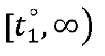
    Figure imgb0361
    is estimated according to the following equation set 10-3: TP w = min Q w t w , i charging , bat _ cap i RE i t w
    Figure imgb0362
    the reserved charging duration T w , i charging
    Figure imgb0363
    of the electric vehicle i at the charging pile jw is estimated according to the following Equation 10-4: T w , i charging = TP w ÷ P w out
    Figure imgb0364
    the remaining electric quantity of the reserved charging start time t w , i charging
    Figure imgb0365
    corresponding to the charging pile j w is E t w , i charging = Q w t w , i charging
    Figure imgb0366
    , the remaining electric quantity of the reserved charging end time t w , i charging + T w , i charging
    Figure imgb0367
    corresponding to the charging pile jw is E t w , i charging + T w , i charging
    Figure imgb0368
    = E t w , i charging TP w
    Figure imgb0369
    ;
    the above variables in the equations in Step (10-1-3) are defined as follows: t w , i charging
    Figure imgb0370
    is the reserved charging start time of the electric vehicle i at the charging pile jw; tw is the estimated time when the electric vehicle i arrives at the charging pile jw ; Q w t w , i charging
    Figure imgb0371
    is the allocable electricity quantity of the charging pile jw in t 1 °
    Figure imgb0372
    ; E t 1 °
    Figure imgb0373
    is the remaining electric quantity of the charging pile jw at the reserved charging end time t 1 °
    Figure imgb0374
    corresponding to the preceding vehicle i 1; p storage(t) is the predicted energy storage power of the charging pile jw at the corresponding time t, which is predicted by the prior art method; P w out
    Figure imgb0375
    is a constant output power of the charging pile jw ; E rated is the rated electricity quantity of the energy storage battery of the charging pile jw; t rated is the time when the energy storage of the charging pile jw reaches the rated electricity quantity E rated in t 1 °
    Figure imgb0376
    ; bat_capi is the rated electricity quantity of the power battery of the electric vehicle i, REi (tw ) is the estimated remaining electric quantity of the electric vehicle i at the time tw when the electric vehicle arrives at the charging pile jw; TPw is the reserved allocated electricity quantity of the electric vehicle i in t 1 °
    Figure imgb0377
    of the charging pile jw ; T w , i charging
    Figure imgb0378
    is the reserved charging duration of the electric vehicle i at the charging pile jw ;
    (10-1-4), if the idle period of the charging pile jw between tw and tw +σ is an allocable idle period and is finite, assuming that the preceding vehicle i 1 has reserved for charging at the charging pile jw in the period t 1 t 1 °
    Figure imgb0379
    , the reserved allocated electric quantity is TP 1 = E t 1 ° E t 1
    Figure imgb0380
    ; assuming that the preceding vehicle i 2 has reserved for charging at the charging pile jw in the period t 2 t 2 °
    Figure imgb0381
    , the reserved allocated electric quantity is TP 2 = E t 2 ° E t 2
    Figure imgb0382
    ; where t 1 and t 1 °
    Figure imgb0383
    correspond to the reserved charging start time and the reserved charging end time of the preceding vehicle i 1, respectively, t 2 and t 2 °
    Figure imgb0384
    correspond to the reserved charging start time and the reserved charging end time of the preceding vehicle i 2, respectively; t 1 < t 1 ° < t 2 < t 2 °
    Figure imgb0385
    ; E(t 1), E t 1 °
    Figure imgb0386
    , E(t 2) and E t 2 °
    Figure imgb0387
    correspond to the estimated remaining electric quantity of the charging pile jw at the time t 1, t 1 °
    Figure imgb0388
    , t 2 and t 2 °
    Figure imgb0389
    ; t 1 ° t 2
    Figure imgb0390
    is the allocable electricity quantity idle period, the precondition for the charging pile jw to allow the electric vehicle i to jump a queue to reserve for charging in the allocable electricity quantity idle period t 1 ° t 2
    Figure imgb0391
    is to not affect the reserved allocated electricity quantity and the reserved charging start and end time of other preceding vehicles that have already reserved for charging after this period t 1 ° t 2
    Figure imgb0392
    , that is, ensuring that the reserved allocated electricity quantity TP 2 of the preceding vehicle i 2 in the reserved charging period t 2 t 2 °
    Figure imgb0393
    remains unchanged first, that is, meeting the following Equation 10-5: TP 2 E t 1 ° + t 1 ° t w , i charging p storage t × d t P w out × t 3 ° t w , i charging + t 3 ° t 2 p storage t × d t
    Figure imgb0394
    the constraint condition of Equation 10-5 is: { E t 1 ° + t 1 ° t w , i charging p storage t × d t P w out × t 3 ° t w , i charging + t 3 ° t 2 p storage t × d t E rated 0 E t 1 ° + t 1 ° t w , i charging p storage t × d t E rated P w out × t 3 ° t w , i charging E t 1 ° + t 1 ° t w , i charging p storage t × d t t 1 < t 1 ° t w , i charging < t 3 ° < t 2 < t 2 °
    Figure imgb0395
    according to Equation 10-5 and its constraint condition, calculating the latest charging end time t 3 °
    Figure imgb0396
    of the electric vehicle i when the charging pile jw allows the electric vehicle i to jump a queue for charging, and estimating the allocable electric quantity Q w t w , i charging
    Figure imgb0397
    of the charging pile jw in the allocable electric quantity idle period t 1 ° t 2
    Figure imgb0398
    according to the following equation set 10-6: { Q w t w , i charging = E t 1 ° + t 1 ° t w , i charging p storage t × d t , when t w , i charging < t rated Q w t w , i charging = E rated , when t rated t w , i charging < t 3 ° and t 3 ° t w , i charging > E rated P w out Q w t w , i charging = P w out × t 3 ° t w , i charging , when t rated t w , i charging < t 3 ° and t 3 ° t w , i charging E rated P w out
    Figure imgb0399
    in the Equation 10-5 and Equation 10-6, estimating the reserved charging start time t w , i charging
    Figure imgb0400
    of the electric vehicle i at the charging pile jw according to the following Equation 10-7: t w , i charging = max t 1 ° t w
    Figure imgb0401
    obtaining Q w t w , i charging
    Figure imgb0402
    according to Equation 10-6, and estimating the reserved allocated electric quantity TPw of the electric vehicle i at the charging pile jw according to the following Equation 10-8: TP w = min Q w t w , i charging , bat _ cap i RE i t w
    Figure imgb0403
    obtaining TPw according to Equation 10-8, and estimating the reserved allocated charging duration T w , i charging
    Figure imgb0404
    of the electric vehicle i at the charging pile jw according to the following Equation 10-8: T w , i charging = TP w ÷ P w out
    Figure imgb0405
    if there are other preceding vehicles that reserve for charging at the charging pile jw before the electric vehicle i, but the time for reserving for charging is after the period t 2 t 2 °
    Figure imgb0406
    of the preceding vehicle i 2 reserved for charging, the precondition for the charging pile jw to allow the electric vehicle i to jump a queue to reserve for charging in the allocable electricity quantity idle period t 1 ° t 2
    Figure imgb0407
    is that in addition to ensuring that the reserved allocated electricity quantity TP 2 of the preceding vehicle i 2 in the reserved charging period t 2 t 2 °
    Figure imgb0408
    remains unchanged, it is also necessary to ensure that the reserved start and end time and the reserved allocated electricity quantity of all other preceding vehicles remain unchanged, and the specific methods are as follows:
    assuming that there are other preceding vehicles i 4 that reserve for charging in the period t 4 t 4 °
    Figure imgb0409
    before the electric vehicle i, the reserved allocated electric quantity is TP 4, in which t 2 < t 2 ° < t 4 < t 4 °
    Figure imgb0410
    , TPw also meets the following Equation 10-10: TP 4 E t 1 ° + t 1 ° t w , i charging p storage t × d t TP w + t w , i charging + T w , i charging t 2 p storage t × d t TP 2 + t 2 ° t 4 p storage t × d t
    Figure imgb0411
    if TPw does not meet Equation 10-10, TPw is reduced, and the corresponding T w , i charging
    Figure imgb0412
    is also reduced according to Equation 10-9 until Equation 10-10 is met;
    if after the reserved charging period t 4 t 4 °
    Figure imgb0413
    of the preceding vehicle i 4, there are other preceding vehicles i 5, i 6... reserving for charging at the charging pile jw before the electric vehicle i, the preceding vehicles are processed according to the method of the preceding vehicle i 4 respectively until TPw can ensure that the reserved start and end time and reserved allocated electric quantity of all other preceding vehicles remain unchanged; if TPw is reduced to the preset threshold value, but it is not ensured that the reserved start and end time and the reserved allocated electric quantity of all other preceding vehicles remain unchanged, and the charging pile jw does not allow the electric vehicle i to jump a queue for reserved charging in the idle period t 1 ° t 2
    Figure imgb0414
    , that is, assuming that the reserved allocated electric quantity is TPw =0;
    if the final TPw ≠ 0, the remaining electric quantity of the charging pile jw corresponding to the reserved charging start time t w , i charging
    Figure imgb0415
    is E t w , i charging = E t 1 ° + t 1 ° t w , i charging p storage t × d t
    Figure imgb0416
    , and the remaining electric quantity of the charging pile jw corresponding to the reserved charging end time t w , i charging + T w , i charging
    Figure imgb0417
    is E t w , i charging + T w , i charging = E t w , i charging TP w
    Figure imgb0418
    ;
    the above variables in the equations in Step (10-1-4) are defined as follows: TP 2 is the reserved allocated electricity quantity of the preceding vehicle i 2 in the reserved charging period t 2 t 2
    Figure imgb0419
    ; E t 1
    Figure imgb0420
    is the remaining electric quantity of the charging pile jw at the reserved charging end time t 1
    Figure imgb0421
    corresponding to the preceding vehicle i 1; p storage(t) is the predicted energy storage power of the charging pile jw at the corresponding time t, which is predicted by the prior art method; P w out
    Figure imgb0422
    is a constant output power of the charging pile jw ; t w , i charging
    Figure imgb0423
    is the reserved charging start time of the electric vehicle i at the charging pile jw ; tw is the estimated time when the electric vehicle i arrives at the charging pile jw ; E rated is the rated electricity quantity of the energy storage battery of the charging pile jw ; t 3
    Figure imgb0424
    is the latest charging end time of the electric vehicle i when the charging pile jw allows the electric vehicle i to jump a queue for charging, and Q w t w , i charging
    Figure imgb0425
    is the estimated allocable electric quantity of the charging pile jw in t 1 ° t 2
    Figure imgb0426
    ; t rated is the time when the energy storage of the charging pile jw reaches the rated electricity quantity E rated in t 1 °
    Figure imgb0427
    ; bat_capi is the rated electricity quantity of the power battery of the electric vehicle i, REi (tw ) is the estimated remaining electric quantity of the electric vehicle i at the time tw when the electric vehicle arrives at the charging pile jw ; TPw is the reserved allocated electricity quantity of the electric vehicle i in t 1 °
    Figure imgb0428
    of the charging pile jw ; T w , i charging
    Figure imgb0429
    is the reserved charging duration of the electric vehicle i at the charging pile jw ; TP 4 is the reserved allocated electric quantity of the preceding vehicle i 4 in the period t 4 t 4 °
    Figure imgb0430
    .
  7. The electric-quantity-based path planning method for the electric vehicle compatible with the energy storage charging pile according to claim 6, further comprising Step (10-1-5), wherein every time a Δt time passes, the dispatching system platform executes from Step (10-1-2) to Step (10-1-4) according to the re-updated reserved service list of the charging pile jw , and re-estimates the reserved allocated electric quantity TPw .
  8. The electric-quantity-based path planning method for the electric vehicle compatible with the energy storage charging pile according to claim 3, wherein the reserved allocated electric quantity of the electric vehicle at the charging pile jw is TPw , and when the charging pile jw is a power-grid direct-supply charging pile, the specific step of the method for estimating the reserved allocated electric quantity TPw is as follows:
    (10-2-1), assuming that the electric vehicle is an electric vehicle i, setting a queuing time limit σ after the time tw when the electric vehicle i arrives at the charging pile jw first, where σ is a user-defined time value;
    (10-2-2), according to a reserved service list of the charging pile jw , finding whether there is an idle period between the time tw and the time tw +σ when the electric vehicle i arrives at the charging pile j w; wherein if there is no idle period, estimating the allocable electric quantity Qw (i)=0 that the charging pile jw is capable of supplying to the electric vehicle i; that is, the reserved allocated electricity quantity TPw =0 of the electric vehicle i at the charging pile j w; if there is an idle period, proceeding to Step (10-2-3);
    (10-2-3), if the idle period is infinite, the idle period is denoted as t 1 °
    Figure imgb0431
    , where t 1 °
    Figure imgb0432
    corresponds to the reserved charging end time of the preceding vehicle i 1 and there is no other preceding vehicle reserved for charging after t 1 °
    Figure imgb0433
    ; the reserved allocated electric quantity TPw of the electric vehicle i at the charging pile j w is estimated according to Equation 10-11: TP w = bat _ cap i RE i t w
    Figure imgb0434
    in Equation 10-11, bat_capi is the rated electricity quantity of the power battery of the electric vehicle i, REi (tw ) is the estimated remaining electric quantity of the electric vehicle i at the time tw when the electric vehicle arrives at the charging pile jw ;
    the reserved charging start time of the electric vehicle i at the charging pile jw is t w , i charging =
    Figure imgb0435
    max t 1 ° t w
    Figure imgb0436
    ; where tw is the estimated time when the electric vehicle i arrives at the charging pile jw ;
    obtaining TPw according to Equation 10-11, and the reserved charging duration is T w , i charging = TP w ÷
    Figure imgb0437
    P w out
    Figure imgb0438
    ; where P w out
    Figure imgb0439
    is a constant output power of the charging pile jw ;
    (10-2-4), if the idle period is finite, assuming that the preceding vehicle i 1 has reserved for charging at the charging pile jw in the period t 1 t 1 °
    Figure imgb0440
    ; there is a preceding vehicle i 2 that has reserved for charging at the charging pile jw in the period t 2 t 2 °
    Figure imgb0441
    ; where t 1 and t 1 °
    Figure imgb0442
    correspond to the reserved charging start time and the reserved charging end time of the preceding vehicle i 1, respectively, t 2 and t 2 °
    Figure imgb0443
    correspond to the reserved charging start time and the reserved charging end time of the preceding vehicle i 2, respectively; t 1 < t 1 ° < t 2 < t 2 °
    Figure imgb0444
    ; and the reserved allocated electric quantity TPw of the electric vehicle i at the charging pile jw is estimated according to the following Equation 10-12: TP w = min bat _ cap i RE i t w , P w out × t 2 t w , i charging
    Figure imgb0445
    in Equation 10-12, bat_capi is the rated electricity quantity of the power battery of the electric vehicle i, REi (tw ) is the estimated remaining electric quantity of the electric vehicle i at the time tw when the electric vehicle arrives at the charging pile jw ; P w out

    Figure imgb0446
    is a constant output power of the charging pile jw ; t w , i charging
    Figure imgb0447
    is the reserved charging start time of the electric vehicle i at the charging pile jw , t w , i charging = max t 1 ° t w
    Figure imgb0448
    ;
    the reserved charging duration of the electric vehicle i at the charging pile jw is T w , i charging = TP w ÷
    Figure imgb0449
    P w out
    Figure imgb0450
    .
  9. The electric-quantity-based path planning method for the electric vehicle compatible with the energy storage charging pile according to claim 6 or 8, wherein the time tw when the electric vehicle arrives at the charging pile j w is replaced with tw - θ or tw + θ, where θ is a user-defined duration value.
  10. The electric-quantity-based path planning method for the electric vehicle compatible with the energy storage charging pile according to one of claims 1 to 8, further comprising a method for adjusting the preceding vehicle as follows:
    assuming that prior to the reservation of the electric vehicle i, the existing preceding vehicles reserve for charging and generate their own whole-journey reservation schemes, respectively; when the electric vehicle i reserves for charging according to the electric-quantity-based path planning method for the electric vehicle compatible with the energy storage charging pile, and when the shortest path l z in the selected path set L = {l 1, ··· , la } from the departure place O to the destination D does not meet the whole-journey endurance requirement, adjusting the whole-journey reservation scheme of the preceding vehicle, comprising canceling or reducing the reserved allocated electric quantity of the preceding vehicle at one or more common piles, judging whether the shortest path l z of the electric vehicle i and the path of the original whole-journey reservation scheme of the preceding vehicle meet the whole-journey endurance requirements of the electric vehicle i and the preceding vehicle, respectively, wherein if so, the dispatching system platform generates a whole-journey reservation scheme for the electric vehicle i, and generates a new whole-journey reservation scheme for the preceding vehicle, and the adjustment is successful; if any of the vehicles does not meet the whole-journey endurance requirement, it is impossible to adjust the preceding vehicle and restore the original whole-journey reservation scheme of the preceding vehicle.
  11. An electric quantity reserving method of an energy storage charging pile, comprising the following steps:
    (1) an energy storage charging pile establishes and stores a reserved service list of the pile, and the field contents of the reserved service list comprise an electric vehicle user name, an electric vehicle brand, an vehicle model, reserved charging start time and charging pile remaining electric quantity corresponding to the time, reserved charging end time and charging pile remaining electric quantity corresponding to the time, reserved allocated electric quantity, reserved charging duration, a type of the idle periods and corresponding allocable electricity quantity;
    (2) the energy storage charging pile announces the type of each idle period of the pile and the corresponding allocable electric quantity without affecting the period when the preceding vehicle has reserved for charging and the reserved allocable electric quantity;
    (3) a vehicle-mounted terminal of the electric vehicle is connected with the energy storage charging pile through a wireless network, the type of the idle period and the corresponding allocable electric quantity announced in Step (2) are obtained, and an electric vehicle user selects a suitable idle period as required to reserve for charging the energy storage charging pile through the vehicle-mounted terminal of the electric vehicle;
    (4) after the electric vehicle is reserved, the energy storage charging pile updates the reserved service list of the pile according to the reserved result of Step (3).
  12. The electric quantity reserving method of the energy storage charging pile according to claim 11, wherein the energy storage charging pile announces the type of each idle period of the pile and the corresponding allocable electric quantity in Step (2), and the specific method is as follows:
    the idle period is divided into two types: the energy storage period and the allocable electric quantity idle period of the energy storage charging pile jw ; searching the reserved service list of the charging pile jw , assuming that vehicles have reserved for charging before and after the idle period t 1 ° t 2
    Figure imgb0451
    , if a preceding vehicle i 1 has reserved for charging in the period t 1 t 1 °
    Figure imgb0452
    , the reserved allocated electric quantity is TP 1 = E t 1 ° E t 1
    Figure imgb0453
    ; a preceding vehicle i 2 has reserved for charging in the period t 2 t 2 °
    Figure imgb0454
    , the reserved allocated electric quantity is TP 2 = E t 2 ° E t 2
    Figure imgb0455
    ; where t 1 and t 1 °
    Figure imgb0456
    correspond to the reserved charging start time and the reserved charging end time of the preceding vehicle i 1 respectively, and where t 2 and t 2 °
    Figure imgb0457
    correspond to the reserved charging start time and the reserved charging end time of the preceding vehicle i 2 respectively; t 1 < t 1 < t 2 < t 2
    Figure imgb0458
    ; E(t 1), E t 1
    Figure imgb0459
    , E(t 2) and E t 2
    Figure imgb0460
    correspond to the estimated remaining electric quantity of the charging pile jw at the time t 1, t 1
    Figure imgb0461
    , t 2 and t 2
    Figure imgb0462
    ;
    (A) the types of the idle periods t 1 t 2
    Figure imgb0463
    are announced as follows:
    when the following Equation 9-1 is met, t 1 t 2
    Figure imgb0464
    is announced to be the energy storage period of the energy storage charging pile jw ; { 0 E t 2 E rated and E t 2 = TP 2 E t 2 = E t 1 ° + t 1 ° t 2 p storage t × d t t 1 < t 1 ° < t 2 < t 2 °
    Figure imgb0465
    in Equation 9-1, E rated is the rated electricity quantity of the energy storage battery of the energy storage charging pile jw ; p storage(t) is the predicted energy storage power of the energy storage charging pile jw at the time t, which is predicted by the prior art method;
    the energy storage period of the energy storage charging pile jw is only used for energy storage of this pile, that is, the corresponding allocable electricity quantity is 0;
    (B) the method for announcing the allocable electric quantity idle period of the energy storage charging pile jw is as follows:
    after excluding the energy storage period of the energy storage charging pile jw announced in Step (A) from all the idle periods of the energy storage charging pile jw , the remaining periods are the allocable electricity quantity idle periods of the energy storage charging pile jw ;
    dividing the allocable electric quantity idle period into time points according to a fixed duration ρ, where ρ is a user-defined constant, setting the idle period t 1 t 2
    Figure imgb0466
    as the allocable electric quantity idle period which can be divided into several time points t 1 , t 1 + ρ , t 1 + 2 × ρ , . t 1 + k × ρ , t 1 + k + 1 × ρ , .. t 2
    Figure imgb0467
    , k = 0,1,2,3 ...., ∃k ∈ N, and setting the reserved charging start time of the electric vehicle in the allocable electric quantity idle period as the time point t 1 + k × ρ
    Figure imgb0468
    ; where the allocable electricity quantity idle period of the energy storage charging pile jw must meet the following Equation 9-2: TP 2 E t 1 ° + t 1 ° t 1 ° + k × ρ p storage t × d t P w out × t 3 ° t 1 ° + k × ρ + t 3 ° t 2 p storage t × d t
    Figure imgb0469
    the constraint condition of Equation 9-2 is: { 0 E t 2 ° E rated 0 E t 2 E rated 0 E t 1 ° + t 1 ° t 1 ° + k × ρ p storage t × d t E rated P w out × t 3 ° t 1 ° + k × ρ E t 1 ° + t 1 ° t 1 ° + k × ρ p storage t × d t t 1 < t 1 ° t 1 ° + k × ρ < t 3 ° < t 2 < t 2 °
    Figure imgb0470
    in Equation 9-2 and its constraint conditions, p storage(t) is the predicted energy storage power of the energy storage charging pile jw at the time t, which is predicted by the prior art method; P w out
    Figure imgb0471
    is a constant output power of the charging pile jw ; E rated is the rated electricity quantity of the energy storage battery of the energy storage charging pile jw ; t 3 °
    Figure imgb0472
    is the latest charging end time for an electric vehicle;
    the latest charging end time t 3 °
    Figure imgb0473
    of the electric vehicle can be obtained from Equation 9-2 and its constraint conditions, t 3 ° t 2
    Figure imgb0474
    is the energy storage period of the energy storage charging pile jw ;
    the corresponding allocable electric quantity Qw (t) of the energy storage charging pile jw at the time point t 1 ° + k × ρ
    Figure imgb0475
    in the allocable electricity quantity idle period t 1 ° t 2
    Figure imgb0476
    is estimated according to the following equation set 9-3: { Q w t = E t 1 ° + t 1 ° t 1 ° + k × ρ p storage t × d t , when t 1 ° + k × ρ < t rated Q w t = E rated , when t rated t 1 ° + k × ρ < t 3 ° and t 3 ° t 1 ° + k × ρ > E rated P w out Q w t = P w out × t 3 ° t 1 ° + k × ρ , when t rated t 1 ° + k × ρ and t 3 ° t 1 ° + k × ρ E rated P w out
    Figure imgb0477
    in equation set 9-3, k = 0,1,2,3 ...., ∃k ∈ N; t rated denotes the time when the energy storage of the energy storage charging pile jw reaches the rated electricity quantity, and the definitions of other variables are the same as Equation 9-2 and its constraints;
    announcing the corresponding allocable electric quantity Qw (t) at the time point t 1 ° + k × ρ
    Figure imgb0478
    in the allocable electricity quantity idle period t 1 ° t 2
    Figure imgb0479
    in the reserved service list of the energy storage charging pile jw ; announcing the rest of the time points according to the time point t 1 ° + k × ρ
    Figure imgb0480
    .
  13. The electric quantity reserving method of the energy storage charging pile according to claim 12, wherein the method for announcing the type of the idle period t 1 ° t 2
    Figure imgb0481
    further comprises: every time a Δt time passes, the dispatching system platform re-estimates the comprehensive energy storage electricity quantity t 1 ° t 2 p storage t × d t
    Figure imgb0482
    of the charging pile jw in Equation 9-1, re-estimates and announces the electricity quantity according to Equation 9-1, and updates the reserved service list of the charging pile jw .
  14. The electric quantity reserving method of the energy storage charging pile according to claim 12, wherein the method for announcing the allocable electricity quantity idle period of the energy storage charging pile jw further comprises: every time a Δt time passes, the dispatching system platform re-estimates the comprehensive energy storage electricity quantity t 1 ° t 1 ° + k × ρ p storage t × d t
    Figure imgb0483
    and t 3 ° t 2 p storage t × d t
    Figure imgb0484
    of the charging pile jw in Equation 9-2 and its constraint conditions, re-estimates and announces the electricity quantity according to Equation 9-3, and updates the reserved service list of the charging pile jw .
EP22803901.2A 2021-05-15 2022-05-14 ELECTRIC QUANTITY-BASED TRIP PLANNING METHOD FOR ELECTRIC VEHICLE COMPATIBLE WITH ENERGY STORAGE CHARGING PILE Pending EP4354368A4 (en)

Applications Claiming Priority (2)

Application Number Priority Date Filing Date Title
CN202110530786.8A CN113283623A (en) 2021-05-15 2021-05-15 Electric vehicle electric quantity path planning method compatible with energy storage charging pile
PCT/CN2022/092902 WO2022242579A1 (en) 2021-05-15 2022-05-14 Electric-quantity-based path planning method for electric vehicle compatible with energy storage charging pile

Publications (2)

Publication Number Publication Date
EP4354368A1 true EP4354368A1 (en) 2024-04-17
EP4354368A4 EP4354368A4 (en) 2025-06-11

Family

ID=77279309

Family Applications (1)

Application Number Title Priority Date Filing Date
EP22803901.2A Pending EP4354368A4 (en) 2021-05-15 2022-05-14 ELECTRIC QUANTITY-BASED TRIP PLANNING METHOD FOR ELECTRIC VEHICLE COMPATIBLE WITH ENERGY STORAGE CHARGING PILE

Country Status (6)

Country Link
US (1) US20240265316A1 (en)
EP (1) EP4354368A4 (en)
CN (2) CN113283623A (en)
AU (1) AU2022279109B2 (en)
SA (1) SA523451537B1 (en)
WO (1) WO2022242579A1 (en)

Families Citing this family (16)

* Cited by examiner, † Cited by third party
Publication number Priority date Publication date Assignee Title
CN112418592B (en) * 2020-09-22 2024-03-15 南京林洋电力科技有限公司 A charging pile fault identification and management method
CN113283623A (en) * 2021-05-15 2021-08-20 韦涛 Electric vehicle electric quantity path planning method compatible with energy storage charging pile
CN114611811B (en) * 2022-03-21 2022-10-25 特斯联科技集团有限公司 Low-carbon park optimal scheduling method and system based on EV load participation
CN114841435B (en) * 2022-05-05 2025-04-04 苏州真趣信息科技有限公司 A navigation path planning method and system
CN115800407B (en) * 2023-02-09 2023-05-12 国文电气股份有限公司 Optical storage and charge integrated low-carbon micro-grid system
CN116311657A (en) * 2023-03-22 2023-06-23 南京奥拓电子科技有限公司 Method and system for queuing and calling numbers at business handling outlets based on reminder callers
CN116039576B (en) * 2023-03-22 2023-08-08 宁波禾旭汽车科技有限公司 New energy vehicle battery intelligent replacement system
CN116843136A (en) * 2023-06-21 2023-10-03 众瑞充(江苏)新能源科技有限公司 Charging pile intelligent management system and management method
CN116526535B (en) * 2023-07-03 2023-09-01 国网辽宁省电力有限公司沈阳供电公司 Energy storage method and system for electric vehicle charging station
CN117128966B (en) * 2023-08-02 2024-04-02 山东科技大学 A vehicle charging path planning method and equipment based on multi-factor coupling
CN117002296B (en) * 2023-09-18 2024-04-12 广东天枢新能源科技有限公司 Liquid cooling variable flow control method and system for charging pile
CN117151255B (en) * 2023-10-30 2024-01-26 速源芯(东莞)能源科技有限公司 Modularized energy storage battery charging and discharging scheduling management system
CN117575284B (en) * 2023-12-18 2024-05-28 北京京西速电新能源科技有限公司 Fill electric pile intelligent control platform
CN117539519B (en) * 2024-01-09 2024-04-02 成都智邦科技有限公司 Program batch upgrading method for charging piles
CN117922354B (en) * 2024-03-21 2024-07-12 国广顺能(上海)能源科技有限公司 Mobile power supply vehicle recharging control method, electronic equipment and storage medium
CN120215512B (en) * 2025-05-27 2025-08-15 中国海洋大学 Unmanned ship self-adaptive path tracking control method and device

Family Cites Families (15)

* Cited by examiner, † Cited by third party
Publication number Priority date Publication date Assignee Title
JP2012128633A (en) * 2010-12-15 2012-07-05 Aisin Seiki Co Ltd Electric vehicle charging reservation method and charging reservation device
US10598503B2 (en) * 2012-11-07 2020-03-24 Intertrust Technologies Corporation Vehicle charging path optimization systems and methods
WO2015063967A1 (en) * 2013-10-31 2015-05-07 パナソニック インテレクチュアル プロパティ コーポレーション オブ アメリカ Control method, program, information processing device, and reservation system
CN106163862B (en) * 2014-04-04 2019-07-05 特斯拉公司 Method and computer-readable storage medium for trip planning
CN104864883B (en) * 2015-05-22 2017-09-22 清华大学 Electric automobile paths planning method based on cloud platform
CN105160428B (en) * 2015-08-19 2018-04-06 天津大学 The planing method of electric automobile on highway quick charge station
CN106989752B (en) * 2016-01-20 2020-07-17 马亨德拉雷瓦电动汽车有限公司 Method and system for planning a journey for a vehicle with limited on-board energy
KR20170133763A (en) * 2016-05-26 2017-12-06 현대자동차주식회사 Vehicle system and navigation route selecting method thereof
US20180143029A1 (en) * 2016-06-28 2018-05-24 Faraday&Future Inc. Intelligent system and method for route planning
CN107323300B (en) * 2017-07-26 2019-05-24 河海大学 A kind of-electric car reservation charging method of vehicle conjunctive model of being stood based on road-
CN108162771B (en) * 2017-11-09 2020-11-10 贵州电网有限责任公司电力科学研究院 Intelligent charging navigation method for electric automobile
CN107953798B (en) * 2017-12-28 2020-07-24 北京万开天盛科技有限公司 Electric vehicle navigation method and system based on energy storage charging pile electric quantity guidance
CA3088914C (en) * 2017-12-28 2023-10-03 Tao Wei Navigation method and system for electric vehicles based on electricity quantity guidance of energy-storage charging piles
CN110081900A (en) * 2019-03-27 2019-08-02 苏州市黑甲智能科技有限公司 A kind of charging pile intelligent recommendation method, apparatus, service terminal and storage medium
CN113283623A (en) * 2021-05-15 2021-08-20 韦涛 Electric vehicle electric quantity path planning method compatible with energy storage charging pile

Also Published As

Publication number Publication date
AU2022279109B2 (en) 2025-09-18
CN113283623A (en) 2021-08-20
SA523451537B1 (en) 2025-06-08
EP4354368A4 (en) 2025-06-11
CN114897199B (en) 2024-12-24
AU2022279109A1 (en) 2024-01-04
US20240265316A1 (en) 2024-08-08
WO2022242579A1 (en) 2022-11-24
CN114897199A (en) 2022-08-12

Similar Documents

Publication Publication Date Title
EP4354368A1 (en) Electric-quantity-based path planning method for electric vehicle compatible with energy storage charging pile
US11731524B2 (en) Mobile direct current fast charger customer-vehicle-station matching system
JP5776017B2 (en) Storage battery charging plan support system
US9758145B2 (en) Vehicle energy management device
US9358896B2 (en) Energy management system
US8725331B2 (en) Charge-discharge management apparatus and system for vehicle
EP2768693B1 (en) Method, system and charging station for charging electric vehicles
US20130285608A1 (en) Charging control device, charging control method, and program
CN108955711A (en) A kind of air navigation aid applied to electric car intelligent recharge and discharge
WO2015041366A1 (en) Operation plan creation device and operation plan creation method
CN115100896B (en) An Electric Demand Response Bus Scheduling Method Considering Opportunity Charging Strategy
CN114638460B (en) Operation planning system and operation planning method
US12252028B2 (en) Method for planning a power exchange between a charging infrastructure and an electricity supply grid
CN116007648A (en) A charging route planning and navigation method and system for pure electric vehicles
CN108470224A (en) Charging station selection method, medium and equipment based on electric vehicle charging
CN118266144A (en) Charging plan making system, charging plan making method, and charging plan making program
JP2021191044A (en) Power control system
JP2021019455A (en) Power management device and power management system
CN120725366A (en) Mobile charging pile path planning method and system for electric vehicles
JP2022156628A (en) Operation plan generation device, charging plan generation device, charging system, operation plan generation method, and operation plan generation program
JP7609039B2 (en) Information processing device, system, method, and program
WO2023085334A1 (en) Mobile body charging system and mobile body charging method
EA048883B1 (en) A METHOD OF PATH PLANNING BASED ON THE AMOUNT OF ELECTRICITY REQUIRED FOR AN ELECTRIC VEHICLE USING CHARGING COLUMNS ALONG ITS ROUTE
JP2022123904A (en) hydrogen station
US20250155246A1 (en) Method of generating delivery plan

Legal Events

Date Code Title Description
STAA Information on the status of an ep patent application or granted ep patent

Free format text: STATUS: THE INTERNATIONAL PUBLICATION HAS BEEN MADE

PUAI Public reference made under article 153(3) epc to a published international application that has entered the european phase

Free format text: ORIGINAL CODE: 0009012

STAA Information on the status of an ep patent application or granted ep patent

Free format text: STATUS: REQUEST FOR EXAMINATION WAS MADE

17P Request for examination filed

Effective date: 20231214

AK Designated contracting states

Kind code of ref document: A1

Designated state(s): AL AT BE BG CH CY CZ DE DK EE ES FI FR GB GR HR HU IE IS IT LI LT LU LV MC MK MT NL NO PL PT RO RS SE SI SK SM TR

DAV Request for validation of the european patent (deleted)
DAX Request for extension of the european patent (deleted)
A4 Supplementary search report drawn up and despatched

Effective date: 20250513

RIC1 Information provided on ipc code assigned before grant

Ipc: G06Q 10/06 20230101AFI20250507BHEP