EP4354288A2 - Information processing device, management program, management method, and information processing system - Google Patents
Information processing device, management program, management method, and information processing system Download PDFInfo
- Publication number
- EP4354288A2 EP4354288A2 EP24159943.0A EP24159943A EP4354288A2 EP 4354288 A2 EP4354288 A2 EP 4354288A2 EP 24159943 A EP24159943 A EP 24159943A EP 4354288 A2 EP4354288 A2 EP 4354288A2
- Authority
- EP
- European Patent Office
- Prior art keywords
- information processing
- virtual
- power supply
- processing device
- software
- Prior art date
- Legal status (The legal status is an assumption and is not a legal conclusion. Google has not performed a legal analysis and makes no representation as to the accuracy of the status listed.)
- Granted
Links
Images








Classifications
-
- G—PHYSICS
- G06—COMPUTING OR CALCULATING; COUNTING
- G06F—ELECTRIC DIGITAL DATA PROCESSING
- G06F9/00—Arrangements for program control, e.g. control units
- G06F9/06—Arrangements for program control, e.g. control units using stored programs, i.e. using an internal store of processing equipment to receive or retain programs
- G06F9/44—Arrangements for executing specific programs
- G06F9/455—Emulation; Interpretation; Software simulation, e.g. virtualisation or emulation of application or operating system execution engines
- G06F9/45533—Hypervisors; Virtual machine monitors
- G06F9/45558—Hypervisor-specific management and integration aspects
-
- G—PHYSICS
- G06—COMPUTING OR CALCULATING; COUNTING
- G06F—ELECTRIC DIGITAL DATA PROCESSING
- G06F9/00—Arrangements for program control, e.g. control units
- G06F9/06—Arrangements for program control, e.g. control units using stored programs, i.e. using an internal store of processing equipment to receive or retain programs
- G06F9/44—Arrangements for executing specific programs
- G06F9/4401—Bootstrapping
- G06F9/442—Shutdown
-
- G—PHYSICS
- G06—COMPUTING OR CALCULATING; COUNTING
- G06F—ELECTRIC DIGITAL DATA PROCESSING
- G06F1/00—Details not covered by groups G06F3/00 - G06F13/00 and G06F21/00
- G06F1/26—Power supply means, e.g. regulation thereof
- G06F1/266—Arrangements to supply power to external peripherals either directly from the computer or under computer control, e.g. supply of power through the communication port, computer controlled power-strips
-
- G—PHYSICS
- G06—COMPUTING OR CALCULATING; COUNTING
- G06F—ELECTRIC DIGITAL DATA PROCESSING
- G06F1/00—Details not covered by groups G06F3/00 - G06F13/00 and G06F21/00
- G06F1/26—Power supply means, e.g. regulation thereof
- G06F1/263—Arrangements for using multiple switchable power supplies, e.g. battery and AC
-
- G—PHYSICS
- G06—COMPUTING OR CALCULATING; COUNTING
- G06F—ELECTRIC DIGITAL DATA PROCESSING
- G06F9/00—Arrangements for program control, e.g. control units
- G06F9/06—Arrangements for program control, e.g. control units using stored programs, i.e. using an internal store of processing equipment to receive or retain programs
- G06F9/46—Multiprogramming arrangements
- G06F9/48—Program initiating; Program switching, e.g. by interrupt
- G06F9/4806—Task transfer initiation or dispatching
- G06F9/4843—Task transfer initiation or dispatching by program, e.g. task dispatcher, supervisor, operating system
- G06F9/485—Task life-cycle, e.g. stopping, restarting, resuming execution
-
- G—PHYSICS
- G06—COMPUTING OR CALCULATING; COUNTING
- G06F—ELECTRIC DIGITAL DATA PROCESSING
- G06F9/00—Arrangements for program control, e.g. control units
- G06F9/06—Arrangements for program control, e.g. control units using stored programs, i.e. using an internal store of processing equipment to receive or retain programs
- G06F9/44—Arrangements for executing specific programs
- G06F9/455—Emulation; Interpretation; Software simulation, e.g. virtualisation or emulation of application or operating system execution engines
- G06F9/45533—Hypervisors; Virtual machine monitors
- G06F9/45558—Hypervisor-specific management and integration aspects
- G06F2009/45562—Creating, deleting, cloning virtual machine instances
-
- G—PHYSICS
- G06—COMPUTING OR CALCULATING; COUNTING
- G06F—ELECTRIC DIGITAL DATA PROCESSING
- G06F9/00—Arrangements for program control, e.g. control units
- G06F9/06—Arrangements for program control, e.g. control units using stored programs, i.e. using an internal store of processing equipment to receive or retain programs
- G06F9/44—Arrangements for executing specific programs
- G06F9/455—Emulation; Interpretation; Software simulation, e.g. virtualisation or emulation of application or operating system execution engines
- G06F9/45533—Hypervisors; Virtual machine monitors
- G06F9/45558—Hypervisor-specific management and integration aspects
- G06F2009/45575—Starting, stopping, suspending or resuming virtual machine instances
Definitions
- the present invention relates to an information processing device, an information processing system, a control device, a management method and a computer program.
- JP 2017-187992A discloses that a virtual environment can be realized in which a plurality of OSs are executable independently to each other using a shared hardware resource, in a control device including at least one processor.
- JP 2017-187992A , JP 5664004B , JP 6029165B , and JP 5206750B are examples of background art.
- next processing (such as shutdown of another guest OS) is performed following a set time schedule, without confirming whether or not a guest OS has been shut down (see JP 5664004B and JP 6029165B , for example).
- the shutdown of a guest OS is regarded as completed when a set time has elapsed, and the coupling between a virtual OS (hypervisor), a virtual storage, and the like is released.
- JP 5206750B a configuration in which a power supply device supplies power to a virtual host computer via a tap is disclosed.
- One aspect of the present invention aims to provide a technique for appropriately performing the shutdown of a virtualization system.
- an information processing device has the features of claim 1.
- the virtualization system can be appropriately shut down.
- an information processing system is provided that has the features of claim 2.
- a control device is provided that has the features of claim 8.
- a management method is provided that has the features of claim 11.
- a computer program is provided that has the features of claim 12.
- the information processing device may be realized using a computer, and in this case, a control program for an information processing device that realizes the information processing device on a computer by causing the computer to operate as the units (software elements) included in the information processing device, and a computer-readable storage medium storing the control program also fall within the scope of the present invention.
- the shutdown of a virtualization system can be appropriately performed.
- FIGS. 1 to 7 embodiments according (hereinafter, also denoted as the "present embodiment") will be described based on FIGS. 1 to 7 . Note that the same or corresponding portions are assigned the same reference numerals in the drawings, and descriptions thereof will be omitted.
- the present embodiment will be described taking an information processing system 100 as a representative example of the virtualization system, for example. In order to facilitate the understanding of a server 1 according to one aspect of the present invention, first, an outline of the information processing system 100 will be described using FIG. 1 .
- FIG. 1 is a diagram illustrating a configuration of the information processing system 100 according to the present embodiment.
- the information processing system 100 is a virtualization system that includes the servers 1, UPSs (Uninterruptible Power Supply) 2, and network cards 3.
- UPSs Uninterruptible Power Supply
- the servers 1 are information processing devices, and three servers 1a, 1b, and 1c are shown in FIG. 1 , but the number of servers is not specifically limited.
- the UPSs 2 are uninterruptible power supply devices, and two UPSs 2a and 2b are shown in FIG. 1 , but the number of UPSs is not specifically limited.
- the network cards 3 are control devices for controlling the servers 1 and the UPSs 2, and two network cards 3a and 3b are shown in FIG. 1 , but the number of network cards is not specifically limited.
- the servers 1a, 1b, and 1c are connected to the UPSs 2a and 2b through power cables C1, and are supplied with power therefrom.
- the servers 1a, 1b, and 1c are connected through a network cable C2 so as to be able to communicate to each other.
- the servers 1a, 1b, and 1c are connected to the network cards 3a and 3b through the network cable C2 so as to be able to perform communication.
- the network card 3a is inserted into a slot in a back side of the UPS 2a.
- the network card 3b is inserted into a slot in a back side of the UPS 2b.
- the server 1a includes a control unit 10a, and includes a hypervisor 11, virtual software 12, management software 13, and virtual machines 14, as the software to be executed by the control unit 10a.
- the servers 1b and 1c respectively include control units 10b and 10c, and each include a hypervisor 11 and virtual machines 14 that are software programs to be executed by the control units 10b and 10c.
- the control unit 10a of the server 1a may also be configured to not include the virtual machines 14.
- the hypervisor 11 is a virtual OS that integrally manages other pieces of software in each server, and may be AHV of Nutanix (registered trademark), ESXi of VMware (registered trademark), or the like.
- the virtual software 12 is software for controlling shutdown of the servers 1.
- the management software 13 is software for monitoring the states of virtual machines 14 by communicating with the virtual machines 14 of each server, and may be Prism of Nutanix, vCSA of VMware, or the like.
- the virtual machine 14 is a guest OS, and may be Linux (registered trademark), Windows (registered trademark), or the like.
- the virtual software 12, the management software 13, and the virtual machines 14 operate under the management of the hypervisor 11.
- the virtual software 12 acquires the state of a virtual machine 14 using an API (Application Programming Interface) of the management software 13, and gives an instruction to shut down the virtual machine 14.
- API Application Programming Interface
- the control unit 10a includes, as the virtual software 12, a basic service unit (first management unit) 122 that manages shutdown of a plurality of virtual machines 14 that operates on the hypervisor 11, and a network card service unit (second management unit) 121 that shuts down the server 1a when all of the plurality of virtual machines 14 are shut down by the basic service unit 122.
- the basic service unit 122 upon acquiring information indicating that the shutdown of the plurality of virtual machines 14 is completed, executes shutdown of a virtual machine 14 other than that one virtual machine 14.
- FIG. 2 is a diagram illustrating an outline of the virtual software 12 according to the present embodiment.
- the virtual software 12 generates a user interface screen, and displays the user interface screen on a display. Items as shown in FIG. 2 are displayed on the user interface screen, and a user can refer to the states at this point in time.
- virtual software 12 operates using Free BSD, Web services (Apache, Apache Tomcat), or the like.
- FIG. 3 is a diagram illustrating a detailed configuration of the virtual software 12 and a configuration of a periphery according to the present embodiment.
- the virtual software 12, a network card service unit (daemon) 151, and Apache 152 operate on Free BSD 15.
- the virtual software 12 includes the network card service unit 121, the basic service unit 122, a mail transmission unit 123, a stoppage situation storage unit 124, a controller unit 125, a view unit 126, a Nutanix service unit 127, and a VMware service unit 128.
- the network card service unit 121 communicates with a network card 3.
- the network card service unit 121 includes a network card state acquisition unit 1211, a network card event acquisition unit 1212, a UPS redundancy control unit 1213, and a virtual machine stoppage notification unit 1214.
- the network card state acquisition unit 1211 acquires the state of a UPS 2 and the battery condition from the network card 3 via a CGI (Common Gateway Interface).
- the network card event acquisition unit 1212 acquires a shutdown start event from the network card 3 via the network card service unit (daemon) 151.
- the UPS redundancy control unit 1213 controls the redundancy of the UPS 2 to which the server 1 is connected.
- the virtual machine stoppage notification unit 1214 accepts a notification (virtual machine stop notification) indicating that a virtual machine 14 has stopped from the basic service unit 122. Also, the virtual machine stoppage notification unit 1214 transmits a virtual machine stoppage notification to the network card 3 via the network card service unit (daemon) 151.
- the basic service unit 122 includes a stoppage control unit 1221 and a self stoppage unit 1222.
- the stoppage control unit 1221 includes a priority control unit 12211, a group control unit 12212, and a timeout control unit 12213.
- the stoppage control unit 1221 instructs Prism 131, which is one program of the management software 13, to stop a virtual machine 14 and invalidate the virtualization configuration via the Nutanix service unit 127.
- the stoppage control unit 1221 instructs vCSA 132, which is one program of the management software 13, to stop a virtual machine 14 and invalidate the virtualization configuration via the VMware service unit 128.
- the self stoppage unit 1222 shuts down the Free BSD 15.
- the mail transmission unit 123 acquires the stoppage situations of the virtual machines 14 from the basic service unit 122 and transmits a mail including the stoppage situations of the virtual machines 14 to the user, as needed.
- the stoppage situation storage unit 124 acquires the stoppage situations of the virtual machines 14 from the basic service unit 122 and stores the stoppage situations.
- the controller unit 125 acquires the stoppage situations of the virtual machines 14 from the stoppage situation storage unit 124, and displays a progress chart in a stoppage priority setting screen 16 through the view unit 126 and the Apache 152, or through the Apache 152.
- the management software (third management unit) 13 of the control unit 10a monitors the statuses of the plurality of virtual machines 14, and controls the plurality of virtual machines 14.
- the basic service unit 122 of the virtual software 12 acquires the status information of each of the plurality of virtual machines 14 via the management software 13, and executes shutdown of the plurality of virtual machines 14 via the management software 13.
- the network card service unit 121 of the virtual software 12 shuts down the servers 1 via the network cards 3 that controls the servers 1 and the UPSs 2 that are connected to the servers 1, when all of the plurality of virtual machines 14 are shut down by the basic service unit 122.
- FIG. 4 is a block diagram illustrating a configuration of the UPS 2 according to the present embodiment.
- the UPS 2 includes a power supply unit 61, a control unit 62, a monitoring unit 63, and a communication unit 64.
- the power supply unit 61 When the power from the commercial power supply 4 is normal, the power supply unit 61 receives power supplied from the commercial power supply 4 and supplies the power to the servers 1. Also, when the power from the commercial power supply 4 is anomalous, or power is not supplied, the power supply unit 61 supplies power to the servers 1 from the internal battery 75. The power supply unit 61 switches the power supply (commercial power supply 4 or battery 75), which serves as a power feeding source to the servers 1, in response to the instruction from the control unit 62.
- the control unit 62 controls the opening/closing of an input relay 72 and an output relay 76, and switching of an output switch 79, of the power supply unit 61, in response to the instructions from the monitoring unit 63 and the communication unit 64.
- the monitoring unit 63 monitors the situation of a noise filter 71 of the power supply unit 61, and transmits a monitoring result indicating whether or not the power from the commercial power supply 4 is normal to the control unit 62 and the communication unit 64.
- the communication unit 64 transmits the monitoring result from the monitoring unit 63 to the servers 1. Also, the communication unit 64 makes an instruction regarding the switching of the power supply to the control unit 62 in response to an instruction from the servers 1.
- the power supply unit 61 includes the noise filter 71, the input relay 72, a power line 73, a converter 74, the battery 75, the output relay 76, an inverter 77, a power line 78, the output switch 79, and a noise filter 80.
- the input relay 72 is closed, the output relay 76 is open, and the output switch 79 is switched to the power line 73 side, by the control of the control unit 62.
- the power from the commercial power supply 4 is supplied to the servers 1 via the noise filter 71, the input relay 72, the power line 73, the output switch 79, and the noise filter 80.
- the battery 75 is charged by the power from the commercial power supply 4 via the noise filter 71, the input relay 72, and the converter 74.
- the input relay 72 is open, the output relay 76 is closed, and the output switch 79 is switched to the power line 78 side, by the control of the control unit 62.
- the power from the battery 75 is supplied to the servers 1 via the output relay 76, the inverter 77, the power line 78, the output switch 79, and the noise filter 80. Note that the power from the commercial power supply 4 is not supplied to the servers 1.
- the input relay 72 is closed, the output relay 76 is opened, and the output switch 79 is switched to the power line 73 side, by the control of the control unit 62.
- the power from the commercial power supply 4 is supplied to the servers 1 via the noise filter 71, the input relay 72, the power line 73, the output switch 79, and the noise filter 80. Note that the battery 75 is not charged by the power from the commercial power supply 4.
- FIG. 5 is a block diagram illustrating a configuration of the network card 3 according to the present embodiment.
- the network card 3 includes a control unit 31, a UPS communication unit 32, a network communication unit 33, a monitoring unit 34, and a storage unit 35.
- the control unit 31 controls the operations of the entire network card 3.
- the UPS communication unit 32 communicates with a UPS 2 via the slot of the UPS 2.
- the network communication unit 33 communicates with the servers 1 through the network cable C2, and is a network USB, for example.
- the monitoring unit 34 performs time monitoring when shutdown processing is performed.
- the storage unit 35 stores and reads out data in response to the instruction from the control unit 31, and is an HDD, an SSD, or the like.
- FIG. 6 is a flowchart illustrating processing of the server 1 according to the present embodiment.
- FIG. 6 shows the processing of the virtual software 12 of the control unit 10a of the server 1a. In the following, the processing of the virtual software 12 will be described following FIG. 6 .
- the virtual software 12 acquires information regarding the management software 13 (e.g., information regarding the API).
- the virtual software 12 acquires the operating states of the virtual machines 14 (operating or not) from the API of the management software 13.
- the management software 13 acquires the operating states of the virtual machines 14 in the server 1a, and acquires the operating states of the virtual machines 14 in the servers 1b and 1c via the network cable C2. Also, the management software 13 passes the acquired operating states of the virtual machines 14 to the virtual software 12.
- the virtual software 12 acquires the states of the UPSs 2a and 2b through the API of the management software 13.
- the management software 13 instructs the network cards 3a and 3b to respectively report the states of the UPSs 2a and 2b via the network cable C2. Also, the management software 13 passes the acquired states of the UPSs 2a and 2b to the virtual software 12.
- the virtual software 12 determines whether or not shutdown is needed by referring to the operating states of the virtual machines 14 acquired in step S602, and the states of the UPSs 2a and 2b acquired in step S603. For example, it is determined that the shutdown is needed if an operating virtual machine 14 is present and both of the UPSs 2a and 2b are performing the backup operation.
- step S604 the virtual software 12 executes the processing in step S605. If the shutdown is not needed (NO in step S604), the virtual software 12 again executes the processing in step S601.
- Step S605 First management step
- the virtual software 12 executes shutdown of one virtual machine 14 that is operating via the management software 13 (that is, using the API of the management software 13).
- the virtual software 12 confirms whether or not the operation of the virtual machine 14 regarding which shutdown was executed has stopped via the management software 13. If the operation of the virtual machine 14 has stopped (YES in step S606), the virtual software 12 executes the determination in step S609. If the operation of the virtual machine 14 has not stopped (NO in step S606), the virtual software 12 executes the determination in step S607.
- the virtual software 12 determines whether or not exception handling (e.g., time-out monitoring processing) is to be performed. If exception handling is to be performed (YES in step S607), the virtual software 12 executes the determination in step S608. If exception handling is not to be performed (NO in step S607), the virtual software 12 again executes the determination in step S606.
- exception handling e.g., time-out monitoring processing
- the virtual software 12 executes forced shutdown processing of the virtual machine 14 via the management software 13. Also, the virtual software 12 executes the determination in step S609.
- the virtual software 12 determines whether or not another virtual machine 14 is operating via the management software 13. If another virtual machine 14 is operating (YES in step S609), the virtual software 12 again executes the processing in step S605. If no other virtual machine 14 is operating (NO in step S609), the virtual software 12 executes the processing in step S610.
- Step S610 Second management step
- the virtual software 12 notifies the network cards 3a and 3b of the fact that all of the virtual machines have stopped operation via the management software 13. With this, the shutdown of the servers 1 is performed.
- FIG. 7 is a flowchart illustrating processing of the network card 3 according to the present embodiment. In the following, the processing of the network card 3 will be described following FIG. 7 .
- This processing is executed by the control unit 31 when the network communication unit 33 of the network card 3 has received a notification saying that all of the virtual machines have stopped operation from the virtual software 12.
- the control unit 31 of the network card 3 executes the shutdown of the virtual software 12 via the network communication unit 33 and the network cable C2.
- the control unit 31 executes the shutdown of the management software 13 via the network communication unit 33 and the network cable C2.
- the control unit 31 decouples a virtual storage via the network communication unit 33 and the network cable C2.
- the virtual storage is a virtual storage device that is constituted by (logically coupling) a plurality of physical storage devices (such as an HDD (Hard Disk Drive) and an SSD (Solid State Drive)) in at least one server 1. As a result of releasing the coupling of the virtual storage, each physical storage device can be powered off.
- the physical storage device that constitutes the virtual storage need not be incorporated in or connected to the servers 1, and may be a NAS (Network Attached Storage) that is directly connected to the network cable C2 and is shared by the plurality of servers 1 through the network cable C2, or may also be constituted by a storage device controlled by a server 1 and a NAS.
- NAS Network Attached Storage
- the control unit 31 executes shutdown of the hypervisor 11 via the network communication unit 33 and the network cable C2.
- the control unit 31 executes shutdown of the UPS 2 via the UPS communication unit 32.
- the next processing is performed after grasping the shutdown states of the virtual machines 14, the shutdown of the information processing system 100, which is a virtualization system, can be appropriately performed. Also, if the next processing cannot be executed due to some factor, the next processing is performed after forcibly performing shutdown by timeout processing, and as a result, the information processing system 100 can be shut down. Moreover, as a result of notifying the network card 3 of the fact that all of the virtual machines 14 are shut down, immediate scripts for shutting down the hypervisor 11, which is a virtual OS, decoupling the virtual storage, and the like can be executed.
- Embodiment 2 will be described in the following. Note that, for the convenience of description, structural elements having the same functions as structural elements described in Embodiment 1 are given the same reference signs, and the description thereof will be omitted.
- the screen that is managed by the virtual software 12 and is to be displayed in a display of the server 1 or a remote terminal (not illustrated) will be described.
- FIG. 8 is a diagram illustrating a display screen of a node list according to the present embodiment. As shown in FIG. 8 , the node list shows the states of the servers 1, the UPSs 2, the network cards 3, the virtual machines 14, and the like.
- the server 1 may have a test mode in which the plurality of virtual machines (guest OSs) 14 are shut down following a predetermined order. In this case, upon receiving an instruction to start the test mode that is given by a user operation, the control unit 10 of the server 1 executes the test mode.
- guest OSs virtual machines
- control unit 10 executes stoppage priority acquisition processing for acquiring the stoppage priority indicating the order of stopping the nodes, node stopping processing for sequentially stopping the nodes following the acquired stoppage priority, and shutdown time display processing for displaying, for each node, the period from when stopping was instructed until when stopping completion is reported, as the shutdown time.
- FIG. 9 is a diagram illustrating a screen for displaying the shutdown time and the like of each virtual machine 14 in a stoppage test according to the present embodiment.
- the server 1 may further include a controller unit (display control unit) 125 that generates screen data for displaying the shutdown time of each virtual machine 14 in the test mode.
- a controller unit display control unit 125 that generates screen data for displaying the shutdown time of each virtual machine 14 in the test mode.
- the screen data may further include an estimated time (accumulated time) of the shutdown time of each virtual machine 14, an item indicating whether or not the shutdown of each virtual machine 14 is successful, and a maximum time (time limit of the accumulated time).
- the estimated time is a sum of the shutdown times estimated from the period from when stopping was instructed to each virtual machine 14 until when stopping completion of the virtual machine 14 is reported, which is obtained as a result of the server 1 executing the test mode.
- the maximum time is the period for which the battery 75 can supply power in the backup operation. If the estimated time is the maximum time or less, it can be said that there is no problem because the shutdown of all of the virtual machines 14 can be ended in a period for which the battery 75 can supply power.
- the display control unit When the shutdown of a virtual machine 14 is normally ended, the display control unit generates screen data including a black band corresponding to the virtual machine 14, for example. If the shutdown of a virtual machine 14 is abnormally ended, the display control unit generates the screen data including a red band corresponding to the virtual machine 14, for example.
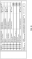
- FIG. 10 is a diagram illustrating a screen for setting a timeout time of each node according to the present embodiment. As shown in FIG. 10 , in the setting screen of the timeout time, necessary nodes can be added and the timeout time can be set.
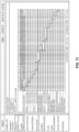
- FIG. 11 is a diagram illustrating a screen for executing a startup test according to the present embodiment.
- the execution screen of the startup test shows the startup order of the nodes, and the startup time of each node.
- the configuration may also be such that the server 1 performs the startup test of the plurality of virtual machines (guest OSs) 14 following a predetermined order.
- guest OSs virtual machines
- the control unit 10 of the server 1 upon receiving an instruction to start the startup test that is given by a user operation, the control unit 10 of the server 1 executes the startup test.
- the startup test is performed in order for the user to confirm that each node normally starts up, after the test mode.
- control unit 10 executes startup priority acquisition processing for acquiring the startup priority indicating the order of starting up the nodes, node startup processing for sequentially starting up the nodes following the acquired startup priority, and startup time display processing for displaying, for each node, the period from when startup was instructed until when startup completion is reported, as the startup time.
- FIG. 12 is a diagram illustrating a screen for setting the startup priority according to the present embodiment. As shown in FIG. 12 , in the setting screen of the startup priority, the user can change the priority of starting up the nodes by operating up and down buttons.
- the user makes an instruction to display a startup priority setting screen by operating the server 1.
- the control unit 10 of the server upon receiving an instruction to display the startup priority setting screen, displays the startup priority setting screen in the display of the server 1. Also, when the startup priority is changed on the setting screen by the user operation, the control unit 10 stores the changed startup priority in a storage unit (not illustrated). Also, the control unit 10, upon receiving an instruction to start up the information processing system 100, reads out the startup priority from the storage unit, and starts up the nodes following the startup priority.
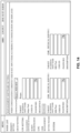
- FIG. 13 is a diagram illustrating a setting screen regarding the UPS 2 according to the present embodiment. As shown in FIG. 13 , in the setting screen of the UPS 2, an operation action regarding an anomaly in an input power supply, a wait time, a stop time, and a stop condition can be set.
- FIG. 14 is a diagram illustrating a setting screen regarding the management software 13 according to the present embodiment.
- Prism which is one program of the management software 13, the IP address/host name of a server 1 to which the Prism is to be connected, the user ID, the password, and the like can be set.
- FIG. 15 is a diagram illustrating a script management screen according to the present embodiment. As shown in FIG. 15 , in the script management screen, the IP addresses/host names of scripts to be executed in the network card 3 can be managed.
- FIG. 16 is a diagram illustrating a basic setting screen according to the present embodiment. As shown in FIG. 16 , in the basic setting screen, settings of the network cards 3, the UPSs 2, the management software 13, the stoppage priority and the startup priority of the nodes can be sequentially performed, and the settings can be confirmed.
- control blocks of the server 1 may be realized by logic circuits (hardware) formed in an integrated circuit (IC chip) or the like, or may be realized by software.
- the server 1 include a computer that executes commands in programs, which are software for implementing the functions.
- This computer includes at least one processor, and a computer-readable recording medium in which the programs are stored, for example.
- the object of the present invention is achieved by the processor reading out the programs from the recording medium and executing the programs, in the computer.
- a CPU central processing unit
- a "non-transitory physical medium” such as a ROM (read only memory), tape, a disk, a card, a semiconductor memory, a programmable logic circuit, or the like can be used as the recording medium.
- a RAM random access memory
- the programs may also be supplied to the computer through any transmission medium capable of transmitting the programs (a communication network, broadcast waves, or the like).
- An aspect of the present invention can be realized as data signals embedded in carrier waves so as to realize the electronic transmission of the programs.
Landscapes
- Engineering & Computer Science (AREA)
- Theoretical Computer Science (AREA)
- Software Systems (AREA)
- General Engineering & Computer Science (AREA)
- Physics & Mathematics (AREA)
- General Physics & Mathematics (AREA)
- Power Engineering (AREA)
- Computer Security & Cryptography (AREA)
- Computer Hardware Design (AREA)
- Power Sources (AREA)
- Hardware Redundancy (AREA)
Abstract
Description
- The present invention relates to an information processing device, an information processing system, a control device, a management method and a computer program.
- A virtualization system is known as a known technique. For example,
JP 2017-187992A -
JP 2017-187992A JP 5664004B JP 6029165B JP 5206750B - However, when the virtualization system is shut down, next processing (such as shutdown of another guest OS) is performed following a set time schedule, without confirming whether or not a guest OS has been shut down (see
JP 5664004B JP 6029165B - Therefore, in the verification at the time of system construction, there is a problem in that it is not possible to confirm whether or not a guest OS has been shut down, and the next processing cannot be performed until a set time has elapsed, and therefore time is wasted in the verification. Also, there is a problem in that if it took a longer time to shut down a guest OS than estimated, the guest OS is not properly shut down.
- Also, the shutdown of a guest OS is regarded as completed when a set time has elapsed, and the coupling between a virtual OS (hypervisor), a virtual storage, and the like is released.
- Note that, in
JP 5206750B - One aspect of the present invention aims to provide a technique for appropriately performing the shutdown of a virtualization system.
- In order to solve the above problem, an information processing device according to one aspect of the invention has the features of
claim 1. - According to this configuration, the virtualization system can be appropriately shut down.
- According to another aspect of the present invention, an information processing system is provided that has the features of
claim 2. - According to a further aspect of the present invention, a control device is provided that has the features of
claim 8. - According to a further aspect of the present invention, a management method is provided that has the features of
claim 11. - According to a further aspect of the present invention, a computer program is provided that has the features of
claim 12. - The information processing device according to aspects of the present invention may be realized using a computer, and in this case, a control program for an information processing device that realizes the information processing device on a computer by causing the computer to operate as the units (software elements) included in the information processing device, and a computer-readable storage medium storing the control program also fall within the scope of the present invention.
- According to aspects of the invention, the shutdown of a virtualization system can be appropriately performed.
-
-
FIG. 1 is a diagram illustrating a configuration of an information processing system according toEmbodiment 1. -
FIG. 2 is a diagram illustrating an outline of a virtual software according to Embodiment 1. -
FIG. 3 is a diagram illustrating a detailed configuration of the virtual software and a configuration of a periphery according toEmbodiment 1. -
FIG. 4 is a block diagram illustrating a configuration of a UPS according toEmbodiment 1. -
FIG. 5 is a block diagram illustrating a configuration of a network card according toEmbodiment 1. -
FIG. 6 is a flowchart illustrating processing of a server according toEmbodiment 1. -
FIG. 7 is a flowchart illustrating processing of a network card according toEmbodiment 1. -
FIG. 8 is a diagram illustrating a display screen of a node list according toEmbodiment 2. -
FIG. 9 is a diagram illustrating a screen for displaying a shutdown time and the like of each virtual machine in a stoppage test according to Embodiment 2. -
FIG. 10 is a diagram illustrating a screen for setting a timeout time of each node according toEmbodiment 2. -
FIG. 11 is a diagram illustrating a screen for executing a startup test according to Embodiment 2. -
FIG. 12 is a diagram illustrating a screen for setting a startup priority according to Embodiment 2. -
FIG. 13 is a diagram illustrating a setting screen regarding a UPS according toEmbodiment 2. -
FIG. 14 is a diagram illustrating a setting screen regarding a management software according to Embodiment 2. -
FIG. 15 is a diagram illustrating a script management screen according toEmbodiment 2. -
FIG. 16 is a diagram illustrating a basic setting screen according toEmbodiment 2. - Hereinafter, embodiments according (hereinafter, also denoted as the "present embodiment") will be described based on
FIGS. 1 to 7 . Note that the same or corresponding portions are assigned the same reference numerals in the drawings, and descriptions thereof will be omitted. The present embodiment will be described taking aninformation processing system 100 as a representative example of the virtualization system, for example. In order to facilitate the understanding of aserver 1 according to one aspect of the present invention, first, an outline of theinformation processing system 100 will be described usingFIG. 1 . -
FIG. 1 is a diagram illustrating a configuration of theinformation processing system 100 according to the present embodiment. As shown inFIG. 1 , theinformation processing system 100 is a virtualization system that includes theservers 1, UPSs (Uninterruptible Power Supply) 2, andnetwork cards 3. - The
servers 1 are information processing devices, and threeservers FIG. 1 , but the number of servers is not specifically limited. The UPSs 2 are uninterruptible power supply devices, and twoUPSs FIG. 1 , but the number of UPSs is not specifically limited. Thenetwork cards 3 are control devices for controlling theservers 1 and theUPSs 2, and twonetwork cards FIG. 1 , but the number of network cards is not specifically limited. - The
servers servers servers network cards network card 3a is inserted into a slot in a back side of the UPS 2a. Thenetwork card 3b is inserted into a slot in a back side of the UPS 2b. - As shown in
FIG. 1 , the server 1a includes acontrol unit 10a, and includes ahypervisor 11,virtual software 12,management software 13, andvirtual machines 14, as the software to be executed by thecontrol unit 10a. Theservers control units hypervisor 11 andvirtual machines 14 that are software programs to be executed by thecontrol units control unit 10a of the server 1a may also be configured to not include thevirtual machines 14. - The
hypervisor 11 is a virtual OS that integrally manages other pieces of software in each server, and may be AHV of Nutanix (registered trademark), ESXi of VMware (registered trademark), or the like. Thevirtual software 12 is software for controlling shutdown of theservers 1. Themanagement software 13 is software for monitoring the states ofvirtual machines 14 by communicating with thevirtual machines 14 of each server, and may be Prism of Nutanix, vCSA of VMware, or the like. Thevirtual machine 14 is a guest OS, and may be Linux (registered trademark), Windows (registered trademark), or the like. - The
virtual software 12, themanagement software 13, and thevirtual machines 14 operate under the management of thehypervisor 11. Thevirtual software 12 acquires the state of avirtual machine 14 using an API (Application Programming Interface) of themanagement software 13, and gives an instruction to shut down thevirtual machine 14. - As shown in
FIG. 1 , thecontrol unit 10a includes, as thevirtual software 12, a basic service unit (first management unit) 122 that manages shutdown of a plurality ofvirtual machines 14 that operates on thehypervisor 11, and a network card service unit (second management unit) 121 that shuts down the server 1a when all of the plurality ofvirtual machines 14 are shut down by thebasic service unit 122. Thebasic service unit 122, upon acquiring information indicating that the shutdown of the plurality ofvirtual machines 14 is completed, executes shutdown of avirtual machine 14 other than that onevirtual machine 14. -
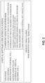
FIG. 2 is a diagram illustrating an outline of thevirtual software 12 according to the present embodiment. Thevirtual software 12 generates a user interface screen, and displays the user interface screen on a display. Items as shown inFIG. 2 are displayed on the user interface screen, and a user can refer to the states at this point in time. That is, on the user interface screen, items relating to the states of theUPSs 2, control of the UPSs 2 (such as redundancy control), notifications to the UPSs 2 (such as stoppage of a virtual machine), communication with thehypervisors 11, the states of thevirtual machines 14 via thehypervisors 11, stoppages of thevirtual machines 14 via thehypervisors 11, shutdown control (priority, group, exception handling) of thevirtual machine 14, shutdown processing of thevirtual software 12, mail notifications, and user interface screen control (setting, updating, saving), are displayed, for example. - Note that the
virtual software 12 operates using Free BSD, Web services (Apache, Apache Tomcat), or the like. -
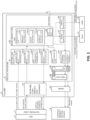
FIG. 3 is a diagram illustrating a detailed configuration of thevirtual software 12 and a configuration of a periphery according to the present embodiment. As shown inFIG. 3 , thevirtual software 12, a network card service unit (daemon) 151, andApache 152 operate onFree BSD 15. - The
virtual software 12 includes the networkcard service unit 121, thebasic service unit 122, amail transmission unit 123, a stoppagesituation storage unit 124, acontroller unit 125, aview unit 126, aNutanix service unit 127, and aVMware service unit 128. - The network
card service unit 121 communicates with anetwork card 3. The networkcard service unit 121 includes a network cardstate acquisition unit 1211, a network cardevent acquisition unit 1212, a UPSredundancy control unit 1213, and a virtual machinestoppage notification unit 1214. - The network card
state acquisition unit 1211 acquires the state of aUPS 2 and the battery condition from thenetwork card 3 via a CGI (Common Gateway Interface). The network cardevent acquisition unit 1212 acquires a shutdown start event from thenetwork card 3 via the network card service unit (daemon) 151. The UPSredundancy control unit 1213 controls the redundancy of theUPS 2 to which theserver 1 is connected. The virtual machinestoppage notification unit 1214 accepts a notification (virtual machine stop notification) indicating that avirtual machine 14 has stopped from thebasic service unit 122. Also, the virtual machinestoppage notification unit 1214 transmits a virtual machine stoppage notification to thenetwork card 3 via the network card service unit (daemon) 151. - The
basic service unit 122 includes astoppage control unit 1221 and aself stoppage unit 1222. Thestoppage control unit 1221 includes apriority control unit 12211, agroup control unit 12212, and atimeout control unit 12213. Thestoppage control unit 1221 instructsPrism 131, which is one program of themanagement software 13, to stop avirtual machine 14 and invalidate the virtualization configuration via theNutanix service unit 127. Also, thestoppage control unit 1221 instructs vCSA 132, which is one program of themanagement software 13, to stop avirtual machine 14 and invalidate the virtualization configuration via theVMware service unit 128. - The
self stoppage unit 1222 shuts down theFree BSD 15. - The
mail transmission unit 123 acquires the stoppage situations of thevirtual machines 14 from thebasic service unit 122 and transmits a mail including the stoppage situations of thevirtual machines 14 to the user, as needed. The stoppagesituation storage unit 124 acquires the stoppage situations of thevirtual machines 14 from thebasic service unit 122 and stores the stoppage situations. Thecontroller unit 125 acquires the stoppage situations of thevirtual machines 14 from the stoppagesituation storage unit 124, and displays a progress chart in a stoppagepriority setting screen 16 through theview unit 126 and theApache 152, or through theApache 152. - The management software (third management unit) 13 of the
control unit 10a monitors the statuses of the plurality ofvirtual machines 14, and controls the plurality ofvirtual machines 14. Thebasic service unit 122 of thevirtual software 12 acquires the status information of each of the plurality ofvirtual machines 14 via themanagement software 13, and executes shutdown of the plurality ofvirtual machines 14 via themanagement software 13. - Also, the network
card service unit 121 of thevirtual software 12 shuts down theservers 1 via thenetwork cards 3 that controls theservers 1 and theUPSs 2 that are connected to theservers 1, when all of the plurality ofvirtual machines 14 are shut down by thebasic service unit 122. -
FIG. 4 is a block diagram illustrating a configuration of theUPS 2 according to the present embodiment. As shown inFIG. 4 , theUPS 2 includes apower supply unit 61, acontrol unit 62, amonitoring unit 63, and acommunication unit 64. - When the power from the
commercial power supply 4 is normal, thepower supply unit 61 receives power supplied from thecommercial power supply 4 and supplies the power to theservers 1. Also, when the power from thecommercial power supply 4 is anomalous, or power is not supplied, thepower supply unit 61 supplies power to theservers 1 from theinternal battery 75. Thepower supply unit 61 switches the power supply (commercial power supply 4 or battery 75), which serves as a power feeding source to theservers 1, in response to the instruction from thecontrol unit 62. - The
control unit 62 controls the opening/closing of aninput relay 72 and anoutput relay 76, and switching of anoutput switch 79, of thepower supply unit 61, in response to the instructions from themonitoring unit 63 and thecommunication unit 64. Themonitoring unit 63 monitors the situation of anoise filter 71 of thepower supply unit 61, and transmits a monitoring result indicating whether or not the power from thecommercial power supply 4 is normal to thecontrol unit 62 and thecommunication unit 64. Thecommunication unit 64 transmits the monitoring result from themonitoring unit 63 to theservers 1. Also, thecommunication unit 64 makes an instruction regarding the switching of the power supply to thecontrol unit 62 in response to an instruction from theservers 1. - As shown in
FIG. 4 , thepower supply unit 61 includes thenoise filter 71, theinput relay 72, apower line 73, aconverter 74, thebattery 75, theoutput relay 76, aninverter 77, apower line 78, theoutput switch 79, and anoise filter 80. - In a normal operation, the
input relay 72 is closed, theoutput relay 76 is open, and theoutput switch 79 is switched to thepower line 73 side, by the control of thecontrol unit 62. In this case, the power from thecommercial power supply 4 is supplied to theservers 1 via thenoise filter 71, theinput relay 72, thepower line 73, theoutput switch 79, and thenoise filter 80. Also, thebattery 75 is charged by the power from thecommercial power supply 4 via thenoise filter 71, theinput relay 72, and theconverter 74. - In a backup operation, the
input relay 72 is open, theoutput relay 76 is closed, and theoutput switch 79 is switched to thepower line 78 side, by the control of thecontrol unit 62. In this case, the power from thebattery 75 is supplied to theservers 1 via theoutput relay 76, theinverter 77, thepower line 78, theoutput switch 79, and thenoise filter 80. Note that the power from thecommercial power supply 4 is not supplied to theservers 1. - When an anomaly occurs in the
converter 74, theinverter 77, or the like of thepower supply unit 61, theinput relay 72 is closed, theoutput relay 76 is opened, and theoutput switch 79 is switched to thepower line 73 side, by the control of thecontrol unit 62. In this case, the power from thecommercial power supply 4 is supplied to theservers 1 via thenoise filter 71, theinput relay 72, thepower line 73, theoutput switch 79, and thenoise filter 80. Note that thebattery 75 is not charged by the power from thecommercial power supply 4. -
FIG. 5 is a block diagram illustrating a configuration of thenetwork card 3 according to the present embodiment. As shown inFIG. 5 , thenetwork card 3 includes acontrol unit 31, aUPS communication unit 32, anetwork communication unit 33, amonitoring unit 34, and astorage unit 35. Thecontrol unit 31 controls the operations of theentire network card 3. TheUPS communication unit 32 communicates with aUPS 2 via the slot of theUPS 2. Thenetwork communication unit 33 communicates with theservers 1 through the network cable C2, and is a network USB, for example. Themonitoring unit 34 performs time monitoring when shutdown processing is performed. Thestorage unit 35 stores and reads out data in response to the instruction from thecontrol unit 31, and is an HDD, an SSD, or the like. -
FIG. 6 is a flowchart illustrating processing of theserver 1 according to the present embodiment.FIG. 6 shows the processing of thevirtual software 12 of thecontrol unit 10a of the server 1a. In the following, the processing of thevirtual software 12 will be described followingFIG. 6 . - In the server 1a, the
virtual software 12 acquires information regarding the management software 13 (e.g., information regarding the API). - The
virtual software 12 acquires the operating states of the virtual machines 14 (operating or not) from the API of themanagement software 13. In this case, themanagement software 13 acquires the operating states of thevirtual machines 14 in the server 1a, and acquires the operating states of thevirtual machines 14 in theservers management software 13 passes the acquired operating states of thevirtual machines 14 to thevirtual software 12. - The
virtual software 12 acquires the states of theUPSs management software 13. In this case, themanagement software 13 instructs thenetwork cards UPSs management software 13 passes the acquired states of theUPSs virtual software 12. - The
virtual software 12 determines whether or not shutdown is needed by referring to the operating states of thevirtual machines 14 acquired in step S602, and the states of theUPSs virtual machine 14 is present and both of theUPSs - If the shutdown is needed (YES in step S604), the
virtual software 12 executes the processing in step S605. If the shutdown is not needed (NO in step S604), thevirtual software 12 again executes the processing in step S601. - The
virtual software 12 executes shutdown of onevirtual machine 14 that is operating via the management software 13 (that is, using the API of the management software 13). - The
virtual software 12 confirms whether or not the operation of thevirtual machine 14 regarding which shutdown was executed has stopped via themanagement software 13. If the operation of thevirtual machine 14 has stopped (YES in step S606), thevirtual software 12 executes the determination in step S609. If the operation of thevirtual machine 14 has not stopped (NO in step S606), thevirtual software 12 executes the determination in step S607. - The
virtual software 12 determines whether or not exception handling (e.g., time-out monitoring processing) is to be performed. If exception handling is to be performed (YES in step S607), thevirtual software 12 executes the determination in step S608. If exception handling is not to be performed (NO in step S607), thevirtual software 12 again executes the determination in step S606. - The
virtual software 12 executes forced shutdown processing of thevirtual machine 14 via themanagement software 13. Also, thevirtual software 12 executes the determination in step S609. - The
virtual software 12 determines whether or not anothervirtual machine 14 is operating via themanagement software 13. If anothervirtual machine 14 is operating (YES in step S609), thevirtual software 12 again executes the processing in step S605. If no othervirtual machine 14 is operating (NO in step S609), thevirtual software 12 executes the processing in step S610. - The
virtual software 12 notifies thenetwork cards management software 13. With this, the shutdown of theservers 1 is performed. -
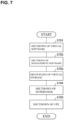
FIG. 7 is a flowchart illustrating processing of thenetwork card 3 according to the present embodiment. In the following, the processing of thenetwork card 3 will be described followingFIG. 7 . This processing is executed by thecontrol unit 31 when thenetwork communication unit 33 of thenetwork card 3 has received a notification saying that all of the virtual machines have stopped operation from thevirtual software 12. - The
control unit 31 of thenetwork card 3 executes the shutdown of thevirtual software 12 via thenetwork communication unit 33 and the network cable C2. - The
control unit 31 executes the shutdown of themanagement software 13 via thenetwork communication unit 33 and the network cable C2. - The
control unit 31 decouples a virtual storage via thenetwork communication unit 33 and the network cable C2. The virtual storage is a virtual storage device that is constituted by (logically coupling) a plurality of physical storage devices (such as an HDD (Hard Disk Drive) and an SSD (Solid State Drive)) in at least oneserver 1. As a result of releasing the coupling of the virtual storage, each physical storage device can be powered off. - Note that the physical storage device that constitutes the virtual storage need not be incorporated in or connected to the
servers 1, and may be a NAS (Network Attached Storage) that is directly connected to the network cable C2 and is shared by the plurality ofservers 1 through the network cable C2, or may also be constituted by a storage device controlled by aserver 1 and a NAS. - The
control unit 31 executes shutdown of thehypervisor 11 via thenetwork communication unit 33 and the network cable C2. - The
control unit 31 executes shutdown of theUPS 2 via theUPS communication unit 32. - According to the present embodiment, as a result of adopting a method in which, instead of performing next processing at the set time, the next processing is performed after grasping the shutdown states of the
virtual machines 14, the shutdown of theinformation processing system 100, which is a virtualization system, can be appropriately performed. Also, if the next processing cannot be executed due to some factor, the next processing is performed after forcibly performing shutdown by timeout processing, and as a result, theinformation processing system 100 can be shut down. Moreover, as a result of notifying thenetwork card 3 of the fact that all of thevirtual machines 14 are shut down, immediate scripts for shutting down thehypervisor 11, which is a virtual OS, decoupling the virtual storage, and the like can be executed. -
Embodiment 2 will be described in the following. Note that, for the convenience of description, structural elements having the same functions as structural elements described inEmbodiment 1 are given the same reference signs, and the description thereof will be omitted. - In the present embodiment, the screen that is managed by the
virtual software 12 and is to be displayed in a display of theserver 1 or a remote terminal (not illustrated) will be described. -
FIG. 8 is a diagram illustrating a display screen of a node list according to the present embodiment. As shown inFIG. 8 , the node list shows the states of theservers 1, theUPSs 2, thenetwork cards 3, thevirtual machines 14, and the like. - The
server 1 may have a test mode in which the plurality of virtual machines (guest OSs) 14 are shut down following a predetermined order. In this case, upon receiving an instruction to start the test mode that is given by a user operation, thecontrol unit 10 of theserver 1 executes the test mode. - In the test mode, the
control unit 10 executes stoppage priority acquisition processing for acquiring the stoppage priority indicating the order of stopping the nodes, node stopping processing for sequentially stopping the nodes following the acquired stoppage priority, and shutdown time display processing for displaying, for each node, the period from when stopping was instructed until when stopping completion is reported, as the shutdown time. -
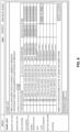
FIG. 9 is a diagram illustrating a screen for displaying the shutdown time and the like of eachvirtual machine 14 in a stoppage test according to the present embodiment. - The
server 1 may further include a controller unit (display control unit) 125 that generates screen data for displaying the shutdown time of eachvirtual machine 14 in the test mode. - As shown in
FIG. 9 , the screen data may further include an estimated time (accumulated time) of the shutdown time of eachvirtual machine 14, an item indicating whether or not the shutdown of eachvirtual machine 14 is successful, and a maximum time (time limit of the accumulated time). - The estimated time is a sum of the shutdown times estimated from the period from when stopping was instructed to each
virtual machine 14 until when stopping completion of thevirtual machine 14 is reported, which is obtained as a result of theserver 1 executing the test mode. The maximum time is the period for which thebattery 75 can supply power in the backup operation. If the estimated time is the maximum time or less, it can be said that there is no problem because the shutdown of all of thevirtual machines 14 can be ended in a period for which thebattery 75 can supply power. - When the shutdown of a
virtual machine 14 is normally ended, the display control unit generates screen data including a black band corresponding to thevirtual machine 14, for example. If the shutdown of avirtual machine 14 is abnormally ended, the display control unit generates the screen data including a red band corresponding to thevirtual machine 14, for example. -
FIG. 10 is a diagram illustrating a screen for setting a timeout time of each node according to the present embodiment. As shown inFIG. 10 , in the setting screen of the timeout time, necessary nodes can be added and the timeout time can be set. -
FIG. 11 is a diagram illustrating a screen for executing a startup test according to the present embodiment. As shown inFIG. 11 , the execution screen of the startup test shows the startup order of the nodes, and the startup time of each node. The configuration may also be such that theserver 1 performs the startup test of the plurality of virtual machines (guest OSs) 14 following a predetermined order. In this case, upon receiving an instruction to start the startup test that is given by a user operation, thecontrol unit 10 of theserver 1 executes the startup test. The startup test is performed in order for the user to confirm that each node normally starts up, after the test mode. - In the startup test, the
control unit 10 executes startup priority acquisition processing for acquiring the startup priority indicating the order of starting up the nodes, node startup processing for sequentially starting up the nodes following the acquired startup priority, and startup time display processing for displaying, for each node, the period from when startup was instructed until when startup completion is reported, as the startup time. -
FIG. 12 is a diagram illustrating a screen for setting the startup priority according to the present embodiment. As shown inFIG. 12 , in the setting screen of the startup priority, the user can change the priority of starting up the nodes by operating up and down buttons. - When the startup priority of the nodes is changed, the user makes an instruction to display a startup priority setting screen by operating the
server 1. Thecontrol unit 10 of theserver 1, upon receiving an instruction to display the startup priority setting screen, displays the startup priority setting screen in the display of theserver 1. Also, when the startup priority is changed on the setting screen by the user operation, thecontrol unit 10 stores the changed startup priority in a storage unit (not illustrated). Also, thecontrol unit 10, upon receiving an instruction to start up theinformation processing system 100, reads out the startup priority from the storage unit, and starts up the nodes following the startup priority. -
FIG. 13 is a diagram illustrating a setting screen regarding theUPS 2 according to the present embodiment. As shown inFIG. 13 , in the setting screen of theUPS 2, an operation action regarding an anomaly in an input power supply, a wait time, a stop time, and a stop condition can be set. -
FIG. 14 is a diagram illustrating a setting screen regarding themanagement software 13 according to the present embodiment. As shown inFIG. 14 , in the setting screen regarding themanagement software 13, Prism, which is one program of themanagement software 13, the IP address/host name of aserver 1 to which the Prism is to be connected, the user ID, the password, and the like can be set. -
FIG. 15 is a diagram illustrating a script management screen according to the present embodiment. As shown inFIG. 15 , in the script management screen, the IP addresses/host names of scripts to be executed in thenetwork card 3 can be managed. -
FIG. 16 is a diagram illustrating a basic setting screen according to the present embodiment. As shown inFIG. 16 , in the basic setting screen, settings of thenetwork cards 3, theUPSs 2, themanagement software 13, the stoppage priority and the startup priority of the nodes can be sequentially performed, and the settings can be confirmed. - The control blocks of the server 1 (specifically, the control unit 10) may be realized by logic circuits (hardware) formed in an integrated circuit (IC chip) or the like, or may be realized by software.
- In the latter case, the
server 1 include a computer that executes commands in programs, which are software for implementing the functions. This computer includes at least one processor, and a computer-readable recording medium in which the programs are stored, for example. Also, the object of the present invention is achieved by the processor reading out the programs from the recording medium and executing the programs, in the computer. A CPU (central processing unit) can be used as the processor, for example. A "non-transitory physical medium" such as a ROM (read only memory), tape, a disk, a card, a semiconductor memory, a programmable logic circuit, or the like can be used as the recording medium. Also, a RAM (random access memory) in which the programs are to be deployed may further be included. Also, the programs may also be supplied to the computer through any transmission medium capable of transmitting the programs (a communication network, broadcast waves, or the like). An aspect of the present invention can be realized as data signals embedded in carrier waves so as to realize the electronic transmission of the programs. - The present invention is not intended to be limited to the embodiments described above, and various changes can be made within the scope defined by the claims. Embodiments achieved by appropriately combining the technical means disclosed in different embodiments also fall within the technical scope of the present invention.
- Some further aspects of the present disclosure, that should not be confused with the appended claims, are as follows:
- Aspect 1: An information processing device (1) that includes a control unit (10),
wherein the control unit (10) includes:- a first management unit (122) configured to manage shutdown of a plurality of guest OSs (14) that operate on a virtual OS (11); and
- a second management unit (121) configured to shut down the information processing device (1) when all of the plurality of guest OSs (14) have been shut down by the first management unit (122), and
- wherein the first management unit (122), upon acquiring information indicating that shutdown of one of the plurality of guest OSs (14) is completed, executes shutdown of a guest OS (14) other than the one guest OS (14).
- Aspect 2: The information processing device (1) according to
Aspect 1,- wherein the control unit (10) includes a third management unit (13) that monitors the statuses of the plurality of guest OSs (14) and controls the plurality of guest OSs (14), and
- the first management unit (122):
- acquires status information of each of the plurality of guest OSs (14) via the third management unit (13), and
- executes shutdown of the plurality of guest OSs (14) via the third management unit (13).
- Aspect 3: The information processing device (1) according to
Aspect
wherein the second management unit (121), when all of the plurality of guest OSs (14) are shut down by the first management unit (122), shuts down the information processing device (1) via a control device (3) that controls the information processing device (1) and an uninterruptible power supply device (2) connected to the information processing device (1). - Aspect 4: The information processing device (1) according to
Aspect 3, having a test mode in which the plurality of guest OSs (14) are shut down following a predetermined order. - Aspect 5: The information processing device (1) according to
Aspect 4, further comprising a display control unit (10) configured to generate screen data for displaying a shutdown time of each guest OS (14) in the test mode. - Aspect 6: The information processing device (1) according to
Aspect 5,
wherein the screen data further includes:- an accumulated time of the shutdown time of each guest OS (14);
- an indication whether or not each guest OS (14) has been successfully shut down; and
- a time limit of the accumulated time.
- Aspect 7: A management program to be executed on a virtual OS (11) to be executed on at least one information processing device (1), the management program causing the at least one information processing device (1) to carry out the steps of:
- a first management step of managing shutdown of a plurality of guest OSs (14) that operate on the virtual OS (11); and
- a second management step of shutting down the at least one information processing device (1) when all of the plurality of guest OSs (14) have been shut down by the first management step,
- wherein, in the first management step, when information indicating that shutdown of one of the plurality of guest OSs (14) is completed is acquired, shutdown of a guest OS (14) other than the one guest OS (14) is executed.
- Aspect 8: A management method to be executed on at least one information processing device (1), the management method causes the at least one information processing device (1) to carry out the steps of:
- a first management step of managing shutdown of a plurality of guest OSs (14) that operate on the virtual OS (11); and
- a second management step of shutting down the at least one information processing device (1) when all of the plurality of guest OSs (14) have been shut down by the first management step,
- wherein, in the first management step, when information indicating that shutdown of one of the plurality of guest OSs (14) is completed is acquired, shutdown of a guest OS (14) other than the one guest OS (14) is executed.
- Aspect 9: An information processing system that includes:
- an information processing device (1) according to any of
Aspects 1 to 6, - an uninterruptible power supply device (2), and
- a control device (3).
- an information processing device (1) according to any of
- Aspect 10: An information processing system that includes a plurality of information processing devices (1) including a control unit (10),
wherein at least one the information processing device (1) is an information processing device (1) according to any ofAspects 1 to 6. -
- 1, 1a, 1b, 1c
- Server (information processing device)
- 2, 2a, 2b
- UPS (uninterruptible power supply device)
- 10, 10a
- Control unit
- 3, 3a, 3b
- Network card (control device)
- 11
- Hypervisor (virtual OS)
- 12
- Virtual software
- 13
- Management software (third management unit)
- 14
- Virtual machine (guest OS)
- 121
- Network card service unit (second management unit)
- 122
- Basic service unit (first management unit)
- 125
- Controller unit (display control unit)
Claims (12)
- An information processing device (1a, 1b, 1c) comprising:a hypervisor (11), a virtual software (12) and a plurality of virtual machines (14) as software to be executed by a control unit (10a, 10b, 10c) of the information processing device (1a, 1b, 1c),wherein the virtual software (12) is configured to execute shutdown of the plurality of virtual machines (14) and to transmit a notification to a control device (3a, 3b) upon executing shutdown of all the virtual machines (14).
- An information processing system (100) that includes:an information processing device (1a, 1b, 1c) according to claim 1,an uninterruptible power supply device (2a, 2b) connected to the information processing device (1a, 1b, 1c), anda control device (3a, 3b) configured to control the information processing device (1a, 1b, 1c) and the uninterruptible power supply device (2a, 2b),the control device (3a, 3b) being configured to shut down the information processing device (1a, 1b, 1c) and to stop power supply from the uninterruptible power supply device (2a, 2b) to the information processing device (1a, 1b, 1c) upon receiving the notification from the virtual software (12).
- The information processing system (100) according to claim 2,
wherein the control device (3a, 3b) is configured to decouple a virtual storage constituted by a plurality of physical storage devices incorporated in, connected to, or shared by the information processing device (1a, 1b, 1c) before stopping power supply from the uninterruptible power supply device (2a, 2b) to the information processing device (1a, 1b, 1c) upon receiving the notification. - The information processing system (100) according to claim 3,
wherein the control device (3) is configured to shut down the hypervisor (11) before stopping power supply from the uninterruptible power supply device (2a, 2b) to the information processing device (1a, 1b, 1c) after decoupling the virtual storage upon receiving the notification. - The information processing system (100) according to any of claims 2 to 4,
wherein the control device (3) is configured to execute shutdown of the virtual software (12) or the virtual software (12) is configured to execute shutdown of itself before stopping power supply from the uninterruptible power supply device (2a, 2b) to the information processing device (1a, 1b, 1c) upon receiving the notification. - The information processing system (100) according to any of claims 2 to 5,wherein the information processing device (1a, 1b, 1c) further comprises a management software (13) as software to be executed by the control unit (10a, 10b, 10c),the virtual software (12) is configured to execute shutdown of the plurality of virtual machines (14) via the management software (13) and to transmit the notification to the control device (3a, 3b) upon executing shutdown of all the virtual machines (14).
- The information processing system (100) according to claim 6,
wherein the control device (3) is configured to shut down the management software (13) before stopping power supply from the uninterruptible power supply device (2a, 2b) to the information processing device (1a, 1b, 1c) upon receiving the notification. - A control device (3) comprising:a control unit (31);a network communication unit (33) configured to communicate with an information processing device (1a, 1b, 1c); anda UPS communication unit (32) configured to communicate with an uninterruptible power supply device (2a, 2b),the control unit (31) being configured to shut down the information processing device (1a, 1b, 1c) via the network communication unit (33) and to stop power supply from the uninterruptible power supply device (2a, 2b) to the information processing device (1a, 1b, 1c) via the UPS communication unit (32) upon receiving a notification, from the information processing device (1a, 1b, 1c) via the network communication unit (33), saying that all virtual machines (14) executed by a control unit (10a, 10b, 10c) of the information processing device (1a, 1b, 1c) have stopped operation.
- The control device (3) according to claim 8,
wherein the control unit (31) is configured to decoupling a virtual storage constituted by a plurality of physical storage devices incorporated in, connected to, or shared by the information processing device (1a, 1b, 1c) before stopping power supply from the uninterruptible power supply device (2a, 2b) to the information processing device (1a, 1b, 1c) upon receiving the notification. - The control device (3) according to claim 8 or 9,
wherein the control unit (31) is configured to shut down the hypervisor (11) before stopping power supply from the uninterruptible power supply device (2a, 2b) to the information processing device (1a, 1b, 1c) after decoupling the virtual storage upon receiving the notification. - A management method to be executed on at least one information processing device (1a) with a hypervisor (11) and a plurality of virtual machines (14),
the management method causing the at least one information processing device (1a) to carry out:a step of executing shutdown of a plurality of virtual machines (14) that operate on the hypervisor (11);a step of transmitting a notification to a control device (3a, 3b) upon shutdown of all the virtual machines (14);a step of shutting down, with the control device (3a, 3b), the information processing device (1a, 1b, 1c) upon receiving the notification from the virtual software (12); anda step of stopping, with the control device (3a, 3b), power supply from the uninterruptible power supply device (2a, 2b) to the information processing device (1a, 1b, 1c) upon receiving the notification from the virtual software (12) - A computer program comprising instructions to cause the system of any of claims 2 to 7 execute the steps of the method of claim 11.
Applications Claiming Priority (2)
| Application Number | Priority Date | Filing Date | Title |
|---|---|---|---|
| JP2019216983A JP7063315B2 (en) | 2019-11-29 | 2019-11-29 | Information processing equipment, management programs, management methods, and information processing systems |
| EP20201466.8A EP3828699B1 (en) | 2019-11-29 | 2020-10-13 | Information processing device, management program, management method, and information processing system |
Related Parent Applications (1)
| Application Number | Title | Priority Date | Filing Date |
|---|---|---|---|
| EP20201466.8A Division EP3828699B1 (en) | 2019-11-29 | 2020-10-13 | Information processing device, management program, management method, and information processing system |
Related Child Applications (1)
| Application Number | Title | Priority Date | Filing Date |
|---|---|---|---|
| EP26190037.7 Division-Into | 2026-07-06 |
Publications (3)
| Publication Number | Publication Date |
|---|---|
| EP4354288A2 true EP4354288A2 (en) | 2024-04-17 |
| EP4354288A3 EP4354288A3 (en) | 2024-10-09 |
| EP4354288B1 EP4354288B1 (en) | 2026-08-12 |
Family
ID=72852430
Family Applications (2)
| Application Number | Title | Priority Date | Filing Date |
|---|---|---|---|
| EP24159943.0A Active EP4354288B1 (en) | 2019-11-29 | 2020-10-13 | Information processing device, management program, management method, and information processing system |
| EP20201466.8A Active EP3828699B1 (en) | 2019-11-29 | 2020-10-13 | Information processing device, management program, management method, and information processing system |
Family Applications After (1)
| Application Number | Title | Priority Date | Filing Date |
|---|---|---|---|
| EP20201466.8A Active EP3828699B1 (en) | 2019-11-29 | 2020-10-13 | Information processing device, management program, management method, and information processing system |
Country Status (5)
| Country | Link |
|---|---|
| US (2) | US20210165676A1 (en) |
| EP (2) | EP4354288B1 (en) |
| JP (1) | JP7063315B2 (en) |
| CN (1) | CN112882558A (en) |
| ES (1) | ES2977632T3 (en) |
Families Citing this family (2)
| Publication number | Priority date | Publication date | Assignee | Title |
|---|---|---|---|---|
| US11960905B2 (en) * | 2020-12-03 | 2024-04-16 | Schneider Electric It Corporation | Network-management-card-assisted shutdown of hyperconverged infrastructure |
| US11822403B1 (en) * | 2022-06-14 | 2023-11-21 | Schneider Electric It Corporation | Systems and methods for intelligent UPS shutdown sequencing in virtualization environments |
Citations (4)
| Publication number | Priority date | Publication date | Assignee | Title |
|---|---|---|---|---|
| JP5206750B2 (en) | 2010-08-09 | 2013-06-12 | サンケン電気株式会社 | Power supply and program |
| JP5664004B2 (en) | 2010-08-05 | 2015-02-04 | 日本電気株式会社 | Information processing system, information processing apparatus, shutdown timing determination method, and program |
| JP6029165B2 (en) | 2012-09-05 | 2016-11-24 | Necエンジニアリング株式会社 | Virtual machine management system, management server, and virtual machine management method |
| JP2017187992A (en) | 2016-04-07 | 2017-10-12 | オムロン株式会社 | Control device, control method and program |
Family Cites Families (20)
| Publication number | Priority date | Publication date | Assignee | Title |
|---|---|---|---|---|
| JPS526750B2 (en) | 1973-11-08 | 1977-02-24 | ||
| JPS6029165B2 (en) | 1977-02-08 | 1985-07-09 | 三菱電機株式会社 | Superconducting compound wire and its manufacturing method |
| US7254733B2 (en) * | 2003-02-18 | 2007-08-07 | International Business Machines Corporation | Method of shutting down virtual machines in an orderly manner |
| US7451443B2 (en) * | 2003-10-01 | 2008-11-11 | Hewlett-Packard Development Company, L.P. | Online computer maintenance utilizing a virtual machine monitor |
| US8683000B1 (en) * | 2006-10-27 | 2014-03-25 | Hewlett-Packard Development Company, L.P. | Virtual network interface system with memory management |
| JP4915224B2 (en) * | 2006-11-30 | 2012-04-11 | オムロン株式会社 | Information processing method, information processing apparatus, recording medium, program, and control apparatus |
| JP2009037271A (en) * | 2007-07-31 | 2009-02-19 | Hitachi Ltd | Method of stopping virtual computer system and computer apparatus |
| JP4924514B2 (en) * | 2008-03-31 | 2012-04-25 | 富士通株式会社 | Virtual machine management program, management server device, and virtual machine management method |
| JP4651127B2 (en) * | 2008-05-21 | 2011-03-16 | 株式会社日立情報システムズ | Virtual machine computer system and fail-safe method of virtual machine computer system |
| JP2010211526A (en) * | 2009-03-10 | 2010-09-24 | Fujitsu Ltd | Program, computer, and control method |
| JP5664362B2 (en) * | 2011-03-10 | 2015-02-04 | サンケン電気株式会社 | Power supply and program |
| JP2012243255A (en) * | 2011-05-24 | 2012-12-10 | Intelligent Willpower Corp | Virtual machine providing system |
| JP5884365B2 (en) * | 2011-09-27 | 2016-03-15 | サンケン電気株式会社 | Power supply and program |
| JP5835342B2 (en) * | 2011-10-31 | 2015-12-24 | 富士通株式会社 | Information processing apparatus, information processing apparatus control method, virtual machine control program, and information processing system |
| WO2013145288A1 (en) * | 2012-03-30 | 2013-10-03 | 富士通株式会社 | Information processing device, virtual machine stop method and program |
| CN103514038B (en) * | 2012-06-26 | 2018-11-27 | 中兴通讯股份有限公司 | A kind of smooth method for closing and system of virtual system |
| US9098457B2 (en) * | 2013-10-31 | 2015-08-04 | Vmware, Inc. | Visualizing disaster recovery plan execution for the cloud |
| US10503237B2 (en) * | 2017-02-13 | 2019-12-10 | Gbs Laboratories, Llc | Mobile device virtualization solution based on bare-metal hypervisor with optimal resource usage and power consumption |
| US10536563B2 (en) * | 2018-02-06 | 2020-01-14 | Nicira, Inc. | Packet handling based on virtual network configuration information in software-defined networking (SDN) environments |
| US11003478B2 (en) * | 2018-12-11 | 2021-05-11 | Schneider Electric It Corporation | Systems and methods for protecting virtual machines running on software-defined storage |
-
2019
- 2019-11-29 JP JP2019216983A patent/JP7063315B2/en active Active
-
2020
- 2020-10-09 CN CN202011075197.7A patent/CN112882558A/en active Pending
- 2020-10-13 ES ES20201466T patent/ES2977632T3/en active Active
- 2020-10-13 EP EP24159943.0A patent/EP4354288B1/en active Active
- 2020-10-13 EP EP20201466.8A patent/EP3828699B1/en active Active
- 2020-10-14 US US17/069,893 patent/US20210165676A1/en active Pending
-
2024
- 2024-03-01 US US18/593,156 patent/US20240427623A1/en active Pending
Patent Citations (4)
| Publication number | Priority date | Publication date | Assignee | Title |
|---|---|---|---|---|
| JP5664004B2 (en) | 2010-08-05 | 2015-02-04 | 日本電気株式会社 | Information processing system, information processing apparatus, shutdown timing determination method, and program |
| JP5206750B2 (en) | 2010-08-09 | 2013-06-12 | サンケン電気株式会社 | Power supply and program |
| JP6029165B2 (en) | 2012-09-05 | 2016-11-24 | Necエンジニアリング株式会社 | Virtual machine management system, management server, and virtual machine management method |
| JP2017187992A (en) | 2016-04-07 | 2017-10-12 | オムロン株式会社 | Control device, control method and program |
Also Published As
| Publication number | Publication date |
|---|---|
| JP2021086528A (en) | 2021-06-03 |
| JP7063315B2 (en) | 2022-05-09 |
| EP3828699A1 (en) | 2021-06-02 |
| US20240427623A1 (en) | 2024-12-26 |
| EP4354288A3 (en) | 2024-10-09 |
| US20210165676A1 (en) | 2021-06-03 |
| EP4354288B1 (en) | 2026-08-12 |
| ES2977632T3 (en) | 2024-08-28 |
| EP3828699B1 (en) | 2024-03-20 |
| CN112882558A (en) | 2021-06-01 |
Similar Documents
| Publication | Publication Date | Title |
|---|---|---|
| US20240427623A1 (en) | Information processing device, management program, management method, and information processing system for performing shutdown of virtualization system | |
| JP6530774B2 (en) | Hardware failure recovery system | |
| US8966489B2 (en) | Information processing device, information processing method, and computer product | |
| US20060041767A1 (en) | Methods, devices and computer program products for controlling power supplied to devices coupled to an uninterruptible power supply (UPS) | |
| US11223515B2 (en) | Cluster system, cluster system control method, server device, control method, and non-transitory computer-readable medium storing program | |
| CN105683921B (en) | Multiprocessor device and method for updating its bootloader | |
| JPWO2009110111A1 (en) | Server apparatus, server apparatus abnormality detection method, and server apparatus abnormality detection program | |
| KR101825561B1 (en) | Dynamic reassignment for multi-operating system devices | |
| WO2018095107A1 (en) | Bios program abnormal processing method and apparatus | |
| US8234486B2 (en) | Managing reboot operations | |
| EP2835716A1 (en) | Information processing device and virtual machine control method | |
| CN108319480A (en) | Bluetooth service starts method, apparatus and electronic equipment | |
| JP7207595B2 (en) | Information processing device, management program, management method, and information processing system | |
| JP7736108B2 (en) | Information processing device, management program, and management method | |
| JP7276526B2 (en) | Information processing device, management program, management method, and information processing system | |
| JP7276566B2 (en) | Information processing system, information processing device, management program, and management method | |
| CN120045423A (en) | Application program operation monitoring method and device, storage medium and electronic equipment | |
| US8843665B2 (en) | Operating system state communication | |
| US9292062B2 (en) | Power supply and program to acquire virtual machine data | |
| CN121209676B (en) | Power Management Systems and Methods | |
| US12493511B2 (en) | Co-tenant alert apparatus, system, and method | |
| CN111913551A (en) | Control method for resetting baseboard management controller | |
| CN117435255A (en) | System startup method and device, storage medium and electronic device | |
| CN112817647A (en) | Method for emptying CMOS and computer equipment | |
| CN120929112A (en) | Firmware configuration method, computer program product and electronic device |
Legal Events
| Date | Code | Title | Description |
|---|---|---|---|
| PUAI | Public reference made under article 153(3) epc to a published international application that has entered the european phase |
Free format text: ORIGINAL CODE: 0009012 |
|
| STAA | Information on the status of an ep patent application or granted ep patent |
Free format text: STATUS: REQUEST FOR EXAMINATION WAS MADE |
|
| 17P | Request for examination filed |
Effective date: 20240227 |
|
| AC | Divisional application: reference to earlier application |
Ref document number: 3828699 Country of ref document: EP Kind code of ref document: P |
|
| AK | Designated contracting states |
Kind code of ref document: A2 Designated state(s): AL AT BE BG CH CY CZ DE DK EE ES FI FR GB GR HR HU IE IS IT LI LT LU LV MC MK MT NL NO PL PT RO RS SE SI SK SM TR |
|
| REG | Reference to a national code |
Ref country code: DE Ref legal event code: R079 Ref country code: DE Ref legal event code: R079 Ref document number: 602020075580 Country of ref document: DE Free format text: PREVIOUS MAIN CLASS: G06F0009455000 Ipc: G06F0009440100 |
|
| PUAL | Search report despatched |
Free format text: ORIGINAL CODE: 0009013 |
|
| AK | Designated contracting states |
Kind code of ref document: A3 Designated state(s): AL AT BE BG CH CY CZ DE DK EE ES FI FR GB GR HR HU IE IS IT LI LT LU LV MC MK MT NL NO PL PT RO RS SE SI SK SM TR |
|
| RIC1 | Information provided on ipc code assigned before grant |
Ipc: G06F 9/455 20180101ALI20240904BHEP Ipc: G06F 9/4401 20180101AFI20240904BHEP |
|
| STAA | Information on the status of an ep patent application or granted ep patent |
Free format text: STATUS: EXAMINATION IS IN PROGRESS |
|
| 17Q | First examination report despatched |
Effective date: 20250512 |
|
| GRAP | Despatch of communication of intention to grant a patent |
Free format text: ORIGINAL CODE: EPIDOSNIGR1 |
|
| STAA | Information on the status of an ep patent application or granted ep patent |
Free format text: STATUS: GRANT OF PATENT IS INTENDED |
|
| INTG | Intention to grant announced |
Effective date: 20260309 |
|
| GRAS | Grant fee paid |
Free format text: ORIGINAL CODE: EPIDOSNIGR3 |
|
| GRAA | (expected) grant |
Free format text: ORIGINAL CODE: 0009210 |
|
| STAA | Information on the status of an ep patent application or granted ep patent |
Free format text: STATUS: THE PATENT HAS BEEN GRANTED |
|
| AC | Divisional application: reference to earlier application |
Ref document number: 3828699 Country of ref document: EP Kind code of ref document: P |
|
| AK | Designated contracting states |
Kind code of ref document: B1 Designated state(s): AL AT BE BG CH CY CZ DE DK EE ES FI FR GB GR HR HU IE IS IT LI LT LU LV MC MK MT NL NO PL PT RO RS SE SI SK SM TR |
|
| P01 | Opt-out of the competence of the unified patent court (upc) registered |
Free format text: CASE NUMBER: UPC_APP_0020736_4354288/2026 Effective date: 20260706 |
|
| REG | Reference to a national code |
Ref country code: CH Ref legal event code: F10 Free format text: ST27 STATUS EVENT CODE: U-0-0-F10-F00 (AS PROVIDED BY THE NATIONAL OFFICE) Effective date: 20260812 Ref country code: GB Ref legal event code: FG4D |