EP4354097A1 - Powder replenisher and powder replenishing method - Google Patents
Powder replenisher and powder replenishing method Download PDFInfo
- Publication number
- EP4354097A1 EP4354097A1 EP23202624.5A EP23202624A EP4354097A1 EP 4354097 A1 EP4354097 A1 EP 4354097A1 EP 23202624 A EP23202624 A EP 23202624A EP 4354097 A1 EP4354097 A1 EP 4354097A1
- Authority
- EP
- European Patent Office
- Prior art keywords
- powder
- controller
- replenishing
- toner
- operating pressure
- Prior art date
- Legal status (The legal status is an assumption and is not a legal conclusion. Google has not performed a legal analysis and makes no representation as to the accuracy of the status listed.)
- Granted
Links
Images




Classifications
-
- G—PHYSICS
- G01—MEASURING; TESTING
- G01G—WEIGHING
- G01G17/00—Apparatus for or methods of weighing material of special form or property
- G01G17/04—Apparatus for or methods of weighing material of special form or property for weighing fluids, e.g. gases, pastes
- G01G17/06—Apparatus for or methods of weighing material of special form or property for weighing fluids, e.g. gases, pastes having means for controlling the supply or discharge
-
- G—PHYSICS
- G03—PHOTOGRAPHY; CINEMATOGRAPHY; ANALOGOUS TECHNIQUES USING WAVES OTHER THAN OPTICAL WAVES; ELECTROGRAPHY; HOLOGRAPHY
- G03G—ELECTROGRAPHY; ELECTROPHOTOGRAPHY; MAGNETOGRAPHY
- G03G15/00—Apparatus for electrographic processes using a charge pattern
- G03G15/06—Apparatus for electrographic processes using a charge pattern for developing
- G03G15/08—Apparatus for electrographic processes using a charge pattern for developing using a solid developer, e.g. powder developer
- G03G15/0822—Arrangements for preparing, mixing, supplying or dispensing developer
- G03G15/0877—Arrangements for metering and dispensing developer from a developer cartridge into the development unit
- G03G15/0879—Arrangements for metering and dispensing developer from a developer cartridge into the development unit for dispensing developer from a developer cartridge not directly attached to the development unit
-
- B—PERFORMING OPERATIONS; TRANSPORTING
- B65—CONVEYING; PACKING; STORING; HANDLING THIN OR FILAMENTARY MATERIAL
- B65B—MACHINES, APPARATUS OR DEVICES FOR, OR METHODS OF, PACKAGING ARTICLES OR MATERIALS; UNPACKING
- B65B1/00—Packaging fluent solid material, e.g. powders, granular or loose fibrous material, loose masses of small articles, in individual containers or receptacles, e.g. bags, sacks, boxes, cartons, cans, or jars
- B65B1/04—Methods of, or means for, filling the material into the containers or receptacles
- B65B1/16—Methods of, or means for, filling the material into the containers or receptacles by pneumatic means, e.g. by suction
-
- B—PERFORMING OPERATIONS; TRANSPORTING
- B65—CONVEYING; PACKING; STORING; HANDLING THIN OR FILAMENTARY MATERIAL
- B65B—MACHINES, APPARATUS OR DEVICES FOR, OR METHODS OF, PACKAGING ARTICLES OR MATERIALS; UNPACKING
- B65B1/00—Packaging fluent solid material, e.g. powders, granular or loose fibrous material, loose masses of small articles, in individual containers or receptacles, e.g. bags, sacks, boxes, cartons, cans, or jars
- B65B1/30—Devices or methods for controlling or determining the quantity or quality or the material fed or filled
- B65B1/32—Devices or methods for controlling or determining the quantity or quality or the material fed or filled by weighing
-
- B—PERFORMING OPERATIONS; TRANSPORTING
- B65—CONVEYING; PACKING; STORING; HANDLING THIN OR FILAMENTARY MATERIAL
- B65B—MACHINES, APPARATUS OR DEVICES FOR, OR METHODS OF, PACKAGING ARTICLES OR MATERIALS; UNPACKING
- B65B1/00—Packaging fluent solid material, e.g. powders, granular or loose fibrous material, loose masses of small articles, in individual containers or receptacles, e.g. bags, sacks, boxes, cartons, cans, or jars
- B65B1/30—Devices or methods for controlling or determining the quantity or quality or the material fed or filled
- B65B1/46—Check-weighing of filled containers or receptacles
-
- G—PHYSICS
- G01—MEASURING; TESTING
- G01G—WEIGHING
- G01G19/00—Weighing apparatus or methods adapted for special purposes not provided for in the preceding groups
-
- G—PHYSICS
- G03—PHOTOGRAPHY; CINEMATOGRAPHY; ANALOGOUS TECHNIQUES USING WAVES OTHER THAN OPTICAL WAVES; ELECTROGRAPHY; HOLOGRAPHY
- G03G—ELECTROGRAPHY; ELECTROPHOTOGRAPHY; MAGNETOGRAPHY
- G03G15/00—Apparatus for electrographic processes using a charge pattern
- G03G15/06—Apparatus for electrographic processes using a charge pattern for developing
- G03G15/08—Apparatus for electrographic processes using a charge pattern for developing using a solid developer, e.g. powder developer
- G03G15/0894—Reconditioning of the developer unit, i.e. reusing or recycling parts of the unit, e.g. resealing of the unit before refilling with toner
Definitions
- Embodiments of this disclosure relate to a powder replenisher and a powder replenishing method.
- Powder replenishers include a powder storage and a powder replenishment container.
- the powder storage stores powder.
- the powder replenishment container is replenished with the powder sent from the powder storage.
- Japanese Patent No. 4860777 discloses a powder replenisher that includes a conveying auger that supplies powder stored in a supply container serving as a powder storage to a weighing container serving as a powder replenishment container.
- a controller of the powder replenisher decreases a replenishing speed.
- a weighing scale serving as a powder measuring instrument measures an amount of the powder inside the weighing container
- the weighing container is replenished with the powder in a target amount.
- the controller Based on an error of the amount of the powder that replenishes the weighing container with respect to the target amount, the controller corrects a stop time when the conveying auger stops. Since the controller corrects the stop time of the conveying auger, the controller adjusts the amount of the powder supplied to the weighing container to the target amount precisely whenever the weighing container is replenished with the powder.
- the controller may not adjust the amount of the powder inside the weighing container to the target amount precisely.
- the powder replenisher includes a powder storage that stores powder.
- a powder replenishment container is replenished with the powder.
- a variable capacity portion has a capacity that is variable.
- a pressure adjuster increases and decreases operating pressure applied to the variable capacity portion.
- the pressure adjuster changes the capacity of the variable capacity portion to transport the powder.
- a powder measuring instrument measures an amount of the powder that replenishes the powder replenishment container.
- An operating pressure detector detects the operating pressure.
- a controller is operatively connected to the pressure adjuster, the powder measuring instrument, and the operating pressure detector.
- the controller performs a precise replenishing mode in which, after the controller determines that the powder replenishment container is replenished with the powder in a predetermined amount, while the controller controls the powder measuring instrument to measure the amount of the powder inside the powder replenishment container, the controller controls the pressure adjuster to replenish the powder replenishment container with the powder in a target amount.
- the controller controls the pressure adjuster to replenish the powder replenishment container with the powder while the controller controls the pressure adjuster based on the operating pressure detected by the operating pressure detector in the precise replenishing mode.
- the powder replenishing method includes storing powder in a powder storage, controlling a pressure adjuster to increase and decrease operating pressure applied to a variable capacity portion, changing a capacity of the variable capacity portion to transport the powder to a powder replenishment container, determining that the powder replenishment container is replenished with the powder in a predetermined amount, starting a precise replenishing mode, measuring an amount of the powder inside the powder replenishment container, detecting the operating pressure applied to the variable capacity portion, controlling the pressure adjuster based on the detected operating pressure, and controlling the pressure adjuster to replenish the powder replenishment container with the powder in a target amount.
- the controller suppresses stress applied to the powder and replenishes the powder replenishment container with the powder in the target amount precisely.
- FIG. 1 is a schematic diagram of the toner replenisher 1 according to the embodiment.
- the toner replenisher 1 includes a toner storage tank 2 and a toner replenishment container 7.
- the toner storage tank 2 serves as a powder storage that stores toner T serving as powder.
- the toner replenishment container 7 serves as a powder replenishment container that is replenished with the toner T.
- the toner replenisher 1 further includes a pneumatically driven pump 5 serving as a positive-displacement pump that transports the toner T from the toner storage tank 2 to the toner replenishment container 7.
- the toner replenisher 1 further includes a weighing scale 9 serving as a powder measuring instrument that measures an amount of the toner T replenishing the toner replenishment container 7.
- the weighing scale 9 is a load cell indicator including a weighing indicator W.
- the toner storage tank 2 accommodates a toner injector tube 2a.
- the toner replenisher 1 further includes a toner suction tube 4. One end of the toner suction tube 4 is disposed inside the toner injector tube 2a. Another end of the toner suction tube 4 is coupled with the pneumatically driven pump 5.
- the toner replenisher 1 further includes a toner transport tube 6. One end of the toner transport tube 6 is coupled with the pneumatically driven pump 5. Another end of the toner transport tube 6 is coupled with a toner discharger 22 that discharges the toner T to the toner replenishment container 7.
- the toner discharger 22 includes a nozzle tube 23 having a tip that is coupled with a nozzle 8.
- the toner replenisher 1 further includes a nozzle elevator 21 that lifts and lowers the toner discharger 22 in a direction X.
- the toner discharger 22 further includes a degassing pump 20 serving as a deaerator that removes air from the toner replenishment container 7.
- the nozzle tube 23 has a double tube structure constructed of an inner tube and an outer tube.
- the inner tube receives the toner T transported from the toner transport tube 6.
- the outer tube receives air inside the toner replenishment container 7 sucked by the degassing pump 20.
- the toner storage tank 2 includes a bottom that mounts a fluidization portion 3 that fluidizes the toner T.
- the fluidization portion 3 includes a ventilation plate and an air intake path.
- the ventilation plate includes a plurality of micropores that ejects air.
- the micropore has a size smaller than a particle size (e.g., a particle diameter) of the toner T.
- the air intake path sends air to the micropores of the ventilation plate.
- the fluidization portion 3 is coupled with a fluidization air supply 30.
- the fluidization air supply 30 sends air to the air intake path of the fluidization portion 3.
- the micropores of the ventilation plate eject air that fluidizes the toner T inside the toner storage tank 2.
- the fluidization air supply 30 that sends air to the air intake path of the fluidization portion 3 is an air compressor, a fan, a blower, or the like.
- the pneumatically driven pump 5 is the positive-displacement pump that includes a transport tube 5a and an air chamber 5b.
- the transport tube 5a serves as a variable capacity portion that shrinks and expands by operating pressure.
- the air chamber 5b accommodates the transport tube 5a and applies operating pressure to the transport tube 5a.
- the transport tube 5a has both ends that mount check valves, respectively, that prevent the toner T from flowing backward.
- the toner replenisher 1 further includes a pump driver 10 serving as a pressure adjuster or a pressure increasing-decreasing portion that intakes and exhausts air inside the air chamber 5b of the pneumatically driven pump 5 and changes pressure inside the air chamber 5b, thus driving the pneumatically driven pump 5.
- the pump driver 10 includes a 3-port solenoid valve 11 serving as a directional control valve, an air compressor 12, and a vacuum pump 13.
- the air compressor 12 sends compressed air into the air chamber 5b.
- the vacuum pump 13 releases air from the air chamber 5b.
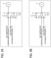
- FIGS. 2A and 2B illustrate driving of the pneumatically driven pump 5.
- the solenoid valve 11 blocks airflow from the vacuum pump 13 and releases airflow from the air compressor 12, sending compressed air into the air chamber 5b of the pneumatically driven pump 5. Accordingly, positive pressure inside the air chamber 5b increases, shrinking the transport tube 5a. Consequently, the toner T inside the transport tube 5a is discharged and transported into the toner transport tube 6.
- the solenoid valve 11 when the solenoid valve 11 is turned on, the solenoid valve 11 blocks airflow from the air compressor 12 and releases airflow from the vacuum pump 13.
- the vacuum pump 13 deflates the air chamber 5b. Accordingly, the air chamber 5b has negative pressure that expands the transport tube 5a. Consequently, the transport tube 5a sucks the toner T from the toner storage tank 2, transporting the toner T through the toner suction tube 4 to the transport tube 5a.
- the pneumatically driven pump 5 transports the toner T, compared to a conveying auger (e.g., a screw auger) that transports the toner T, the pneumatically driven pump 5 decreases stress such as pressure imposed on the toner T. Accordingly, the pneumatically driven pump 5 prevents an external additive to the toner T from being separated from or buried into a surface of the toner T, causing the external additive to achieve a target advantage. Additionally, the pneumatically driven pump 5 prevents toner particles of the toner T from adhering to each other, suppressing aggregation of the toner particles.
- a conveying auger e.g., a screw auger
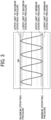
- the solenoid valve 11 As the solenoid valve 11 is turned on and off, as illustrated in FIG. 3 , the solenoid valve 11 changes operating pressure inside the air chamber 5b. Accordingly, the transport tube 5a shrinks and expands repeatedly, transporting the toner T from the toner storage tank 2 to the toner replenishment container 7 continuously. As a switching speed at which the solenoid valve 11 is turned on and off is changed, a replenishing speed at which the toner replenishment container 7 is replenished with the toner T is switched. For example, the replenishing speed defines a replenishing amount of the toner T per unit time in which the toner replenishment container 7 is replenished with the toner T.
- the toner replenisher 1 further includes a pressure gauge 14 (e.g., a pressure indicator (PI)) serving as an operating pressure detector that is disposed in an air channel interposed between the solenoid valve 11 and the pneumatically driven pump 5.
- the pressure gauge 14 detects pressure (e.g., operating pressure) inside the air chamber 5b.
- a controller 100 illustrated in FIG. 4 controls the air compressor 12 and the vacuum pump 13.
- the controller 100 controls the air compressor 12 such that maximum operating pressure inside the air chamber 5b is greater than a lower limit of the maximum operating pressure and smaller than an upper limit of the maximum operating pressure.
- the controller 100 controls the vacuum pump 13 such that minimum operating pressure inside the air chamber 5b is greater than a lower limit of the minimum operating pressure and smaller than an upper limit of the minimum operating pressure.
- FIG. 4 is a block diagram of the toner replenisher 1, illustrating a control system that controls operations for replenishment with the toner T.
- the controller 100 includes a central processing unit (CPU), a random access memory (RAM), a read only memory (ROM), and a flash memory.
- the controller 100 controls driving of various devices of the toner replenisher 1 and performs various arithmetic processing.
- the controller 100 is electrically connected to the nozzle elevator 21, the degassing pump 20, the fluidization air supply 30, the weighing scale 9, a timer 101, the pressure gauge 14, the solenoid valve 11, the air compressor 12, the vacuum pump 13, and the like.
- FIG. 5 is a graph illustrating a relation between a replenishing amount and a replenishing time period of the toner T that replenishes the toner replenishment container 7 while the toner replenisher 1 performs replenishing of the toner T.
- FIG. 5 illustrates a case in which the toner replenishment container 7 is replenished with the toner T in a replenishing amount of 190 g.
- FIG. 5 illustrates phases P1, P2, and P3.
- the toner T in a replenishing amount up to approximately 185 g is supplied to the toner replenishment container 7 quickly.
- the toner replenishment container 7 is replenished with the toner T in the replenishing amount of approximately 185 g
- the toner T in a replenishing amount up to a target replenishing amount of 190 g is supplied to the toner replenishment container 7 precisely.
- the toner T is supplied carefully to prevent the toner replenishment container 7 from overflowing with the toner T due to variation in the replenishing speed and the like.
- the toner replenisher 1 in order to supply the toner T to the toner replenishment container 7 quickly and precisely without overflowing, the toner replenisher 1 has a high-speed replenishing mode serving as an initial replenishing mode, a deceleration replenishing mode, and a precise replenishing mode.
- the high-speed replenishing mode defines degassing replenishing that replenishes the toner replenishment container 7 with the toner T while the degassing pump 20 removes air from the toner replenishment container 7.
- M1 indicates the high-speed replenishing mode, as time-based replenishing, in which the controller 100 controls the degassing pump 20 to degas the toner replenishment container 7.
- M2 indicates the deceleration replenishing mode as amount-based replenishing.
- M3 indicates the precise replenishing mode, as amount-based replenishing, in which the controller 100 controls the pump driver 10 to adjust operating pressure.
- the controller 100 drives the fluidization air supply 30 that fluidizes the toner T inside the toner storage tank 2 with air.
- the controller 100 turns on or off the solenoid valve 11 at a high speed and drives the air compressor 12 and the vacuum pump 13.
- the controller 100 switches turning on and off of the solenoid valve 11 at a high switching speed, replenishing the toner replenishment container 7 with the toner T at a high replenishing speed of the toner T.
- the controller 100 switches turning on and off of the solenoid valve 11 at a low switching speed that is lower than the high switching speed in the high-speed replenishing mode, replenishing the toner replenishment container 7 with the toner T at a low replenishing speed of the toner T, that is lower than the high replenishing speed in the high-speed replenishing mode.
- the controller 100 switches turning on and off of the solenoid valve 11 at a low switching speed that is lower than the low switching speed in the deceleration replenishing mode, replenishing the toner replenishment container 7 with the toner T at a low replenishing speed of the toner T, that is lower than the low replenishing speed in the deceleration replenishing mode.
- the weighing scale 9 does not weigh the replenishing amount of the toner T that replenishes the toner replenishment container 7.
- the toner T is supplied to the toner replenishment container 7 until a target time measured by the timer 101.
- the degassing pump 20 intakes air and sucks up the toner T inside the toner replenishment container 7.
- the weighing scale 9 does not weigh the replenishing amount of the toner T inside the toner replenishment container 7 precisely.
- the toner replenisher 1 replenishes the toner replenishment container 7 with the toner T in the high-speed replenishing mode until the replenishing amount of the toner T inside the toner replenishment container 7, that is weighed by the weighing scale 9, reaches a desired replenishing amount, at worst, the toner T may overflow the toner replenishment container 7.
- the controller 100 decreases the desired replenishing amount in the high-speed replenishing mode, a time period used in the deceleration replenishing mode may increase, resulting in an increased replenishing time period.
- the controller 100 does not control the weighing scale 9 to weigh the replenishing amount of the toner T, thus replenishing the toner replenishment container 7 with the toner T.
- the replenishing speed of the toner T (e.g., the replenishing amount of the toner T per unit time) changes.
- the replenishing speed of the toner T increases, variation in the replenishing speed of the toner T increases.
- variation in the replenishing amount of the toner T inside the toner replenishment container 7 may increase.
- the controller 100 determines the target time period based on an average of last three replenishing speeds of the toner T in the high-speed replenishing mode.
- the controller 100 includes a nonvolatile memory that stores the last three replenishing speeds of the toner T in the high-speed replenishing mode.
- the controller 100 stops the degassing pump 20 and controls the nozzle elevator 21 to lift the nozzle 8 so that the nozzle 8 is situated above the toner T inside the toner replenishment container 7. Subsequently, the controller 100 calculates a replenishing speed of the toner T based on a replenishing amount of the toner T inside the toner replenishment container 7, that is weighed by the weighing scale 9, and an instant target time period. The controller 100 deletes an oldest replenishing speed of the toner T of the last three replenishing speeds of the toner T in the high-speed replenishing mode, that are stored in the nonvolatile memory.
- the controller 100 controls the nonvolatile memory to store the calculated replenishing speed of the toner T.
- the controller 100 calculates the average of the last three replenishing speeds of the toner T in the high-speed replenishing mode, that are stored in the nonvolatile memory.
- the controller 100 calculates the target time period based on the calculated average and the desired replenishing amount of the toner T in the high-speed replenishing mode.
- the controller 100 uses the average of the last three replenishing speeds of the toner T in the high-speed replenishing mode. Alternatively, the controller 100 may use last four or more data to calculate the average.
- the controller 100 determines the target time period in the high-speed replenishing mode by using the average of the plurality of last replenishing speeds of the toner T in the high-speed replenishing mode. Hence, even if the replenishing speed of the toner T changes, the target time period changes automatically. Accordingly, the controller 100 suppresses variation in the replenishing amount of the toner T in the high-speed replenishing mode with respect to the desired replenishing amount. Consequently, the controller 100 prevents the replenishing amount of the toner T in the high-speed replenishing mode from decreasing from the desired replenishing amount excessively, prevents the subsequent, deceleration replenishing mode from extending, and prevents the replenishing time period of the toner T from extending. Additionally, the controller 100 prevents the replenishing amount of the toner T in the high-speed replenishing mode from increasing from the desired replenishing amount of the toner T excessively and prevents the toner T from overflowing the toner replenishment container 7.
- the controller 100 When the high-speed replenishing mode finishes, the controller 100 performs the deceleration replenishing mode in which the replenishing speed of the toner T (e.g., the switching speed of the solenoid valve 11) is lower than the replenishing speed of the toner T in the high-speed replenishing mode.
- the deceleration replenishing mode performs weighing replenishing that does not degas and supplies the toner T while the weighing scale 9 weighs the replenishing amount of the toner T inside the toner replenishment container 7. Since the deceleration replenishing mode does not degas, the weighing scale 9 weighs the replenishing amount of the toner T inside the toner replenishment container 7 precisely.
- the controller 100 replenishes the toner replenishment container 7 with the toner T in a predetermined amount precisely.
- the controller 100 decreases the replenishing speed of the toner T in the deceleration replenishing mode compared to the high-speed replenishing mode, the controller 100 suppresses variation in the replenishing amount of the toner T, that is caused by change in the replenishing speed of the toner T. Hence, the controller 100 prevents the toner T in a replenishing amount greater than the target replenishing amount from being supplied to the toner replenishment container 7 and prevents the toner T from overflowing the toner replenishment container 7.
- the controller 100 decreases the replenishing speed of the toner T stepwise three times, that is, a first deceleration time N1, a second deceleration time N2, and a third deceleration time N3 illustrated in FIG.
- the controller 100 replenishes the toner replenishment container 7 with the toner T in the predetermined amount early.
- the controller 100 supplies the toner T to the toner replenishment container 7 at a replenishing speed that is decreased sufficiently, thus replenishing the toner replenishment container 7 with the toner T precisely to some extent. Accordingly, as illustrated in FIG.
- the controller 100 performs the deceleration replenishing mode until the toner replenishment container 7 is replenished with the toner T in a replenishing amount that is not smaller than a replenishing amount of the toner T with which the controller 100 starts the precise replenishing mode. Hence, the controller 100 shortens a time period of the precise replenishing mode, shortening the replenishing time period of the toner T.
- FIG. 6 is a flowchart of control processes of the deceleration replenishing mode.
- the controller 100 stops the degassing pump 20, controls the nozzle elevator 21 to lift the nozzle 8 so that the nozzle 8 is situated above the toner T inside the toner replenishment container 7. Subsequently, the controller 100 controls the weighing scale 9 to weigh the replenishing amount of the toner T in the high-speed replenishing mode. Subsequently, the controller 100 reads initial parameters from the nonvolatile memory and calculates a replenishing amount of the toner T at a decreased replenishing speed and the like based on the calculated replenishing amount of the toner T in step S1.
- the controller 100 sets the initial parameters in step S1.
- the initial parameters include a first parameter, a second parameter, a third parameter, a fourth parameter, a fifth parameter, a sixth parameter, and a seventh parameter.
- a number of deceleration times is three.
- the controller 100 changes the replenishing speed of the toner T (e.g., the switching speed of the solenoid valve 11)
- the controller 100 decrements the number of deceleration times.
- the switching speed defines a speed for switching turning on and off of the solenoid valve 11.
- the controller 100 changes the switching speed of the solenoid valve 11
- the cycle for changing positive pressure and negative pressure of operating pressure periodically inside the air chamber 5b of the pneumatically driven pump 5 changes. Accordingly, the discharge amount per unit time of the toner T discharged from the pneumatically driven pump 5 changes, thus changing the replenishing speed of the toner T.
- the switching speed at the first deceleration time N1 at which the controller 100 decreases the replenishing speed of the toner T as the second parameter defines a switching speed at an initial deceleration, that is, the first deceleration time N1.
- the controller 100 changes the switching speed to a decreased switching speed that is lower than the switching speed applied at the first deceleration time N1.
- the controller 100 changes the switching speed to a decreased switching speed that is lower than the decreased switching speed applied at the second deceleration time N2.
- the controller 100 calculates the decreased switching speed at the second deceleration time N2 by subtracting a deceleration value from the switching speed at the first deceleration time N1.
- Dv represents the deceleration value.
- Is represents the switching speed at the initial deceleration, that is, the first deceleration time N1.
- Ps represents the switching speed in the precise replenishing mode.
- the controller 100 calculates the decreased switching speed at the third deceleration time N3 by subtracting the deceleration value from the decreased switching speed at the second deceleration time N2.
- the replenishing amount at the decreased switching speed as the fourth parameter defines the replenishing amount of the toner T in the deceleration replenishing mode.
- the controller 100 calculates the replenishing amount at the decreased switching speed by subtracting the replenishing amount of the toner T in the high-speed replenishing mode from a commencement replenishing amount before the precise replenishing mode, that is, a replenishing amount of the toner T when the deceleration replenishing mode finishes.
- the controller 100 calculates an additional weight, as the fifth parameter, by dividing the calculated replenishing amount at the decreased switching speed by 14.
- the controller 100 calculates an additional value, as the sixth parameter, according to a formula (2) below.
- Av N ⁇ N ⁇ Aw
- Av represents the additional value.
- N represents the number of deceleration times.
- Aw represents the additional weight.
- the number of deceleration times is three at the first deceleration time N1, two at the second deceleration time N2, and one at the third deceleration time N3.
- the formula (2) that calculates the additional value as the number of deceleration times increases, the additional value decreases.
- the controller 100 calculates a desired replenishing amount as the seventh parameter.
- the desired replenishing amount defines a target replenishing amount set for each time for decreasing the replenishing speed.
- step S2 the controller 100 determines if a current replenishing amount of the toner T is not smaller than the desired replenishing amount. If the controller 100 determines that the current replenishing amount of the toner T is not smaller than the desired replenishing amount (NO in step S2), the controller 100 switches the switching speed. At the first deceleration time N1 at which the controller 100 decreases the replenishing speed of the toner T, the controller 100 calculates the desired replenishing amount by adding the additional value described above to the replenishing amount in the high-speed replenishing mode.
- the controller 100 calculates the desired replenishing amount by adding the additional value to the desired replenishing amount at the first deceleration time N1.
- the controller 100 calculates the desired replenishing amount by adding the additional value to the desired replenishing amount at the second deceleration time N2.
- the desired replenishing amount at the third deceleration time N3 is equivalent to the commencement replenishing amount before the precise replenishing mode.
- the controller 100 After the controller 100 sets the initial parameters for the first deceleration time N1, the controller 100 switches the solenoid valve 11 at the switching speed at the initial deceleration, thus supplying the toner T at the first deceleration time N1 at the replenishing speed of the toner T that is lower than the replenishing speed of the toner T in the high-speed replenishing mode.
- the controller 100 determines if the current replenishing amount of the toner T inside the toner replenishment container 7, that is weighed by the weighing scale 9, is not smaller than the desired replenishing amount at the first deceleration time N1 (NO in step S2), the controller 100 determines if the current replenishing amount of the toner T inside the toner replenishment container 7 is not smaller than the commencement replenishing amount before the precise replenishing mode in step S3. If the controller 100 determines that the current replenishing amount of the toner T inside the toner replenishment container 7 is smaller than the commencement replenishing amount before the precise replenishing mode (YES in step S3), the controller 100 changes four parameters, that is, an eighth parameter, a ninth parameter, a tenth parameter, and an eleventh parameter, described below in step S4.
- the eighth parameter defines a number of deceleration times for decreasing the replenishing speed of the toner T.
- the ninth parameter defines a switching speed of the solenoid valve 11.
- the tenth parameter defines an additional value.
- the eleventh parameter defines a desired replenishing amount of the toner T.
- the controller 100 decrements the number of deceleration times from three to two.
- the controller 100 changes the switching speed of the solenoid valve 11 to a switching speed at the second deceleration time N2 obtained by subtracting the deceleration value from the switching speed at the initial deceleration (e.g., the first deceleration time N1) as the current switching speed.
- the controller 100 recalculates the additional value.
- the controller 100 adds the recalculated additional value to the desired replenishing amount at the first deceleration time N1, calculating a desired replenishing amount at the second deceleration time N2.
- the controller 100 switches turning on and off of the solenoid valve 11 at the switching speed at the second deceleration time N2, that is changed.
- the controller 100 performs replenishing at the second deceleration time N2 at a replenishing speed of the toner T, that is lower than the replenishing speed of the toner T at the first deceleration time N1.
- the controller 100 determines if the current replenishing amount of the toner T inside the toner replenishment container 7, that is weighed by the weighing scale 9, is not smaller than the desired replenishing amount at the second deceleration time N2 (NO in step S2), the controller 100 determines if the current replenishing amount of the toner T inside the toner replenishment container 7 is smaller than the commencement replenishing amount before the precise replenishing mode. If the controller 100 determines that the current replenishing amount of the toner T inside the toner replenishment container 7 is smaller than the commencement replenishing amount before the precise replenishing mode (YES in step S3), the controller 100 changes the parameters as described above in step S4.
- the controller 100 changes the switching speed of the solenoid valve 11 to a switching speed at the third deceleration time N3 obtained by subtracting the deceleration value from the switching speed at the second deceleration time N2 as the current switching speed.
- the controller 100 decrements the number of deceleration times from two to one.
- the controller 100 recalculates the additional value.
- the controller 100 adds the additional value to the desired replenishing amount at the second deceleration time N2, thus calculating a desired replenishing amount at the third deceleration time N3.
- the desired replenishing amount at the third deceleration time N3 is equivalent to the commencement replenishing amount before the precise replenishing mode.
- the controller 100 switches turning on and off of the solenoid valve 11 at the changed switching speed at the third deceleration time N3, thus performing replenishment at the third deceleration time N3 at the replenishing speed of the toner T, that is lower than the replenishing speed at the second deceleration time N2.
- the desired replenishing amount is equivalent to the commencement replenishing amount before the precise replenishing mode.
- the controller 100 determines that the current replenishing amount of the toner T inside the toner replenishment container 7, that is weighed by the weighing scale 9, is not smaller than the desired replenishing amount at the third deceleration time N3 (NO in step S2), the controller 100 determines that the current replenishing amount of the toner T is not smaller than the commencement replenishing amount before the precise replenishing mode (NO in step S3). Thus, the controller 100 finishes the deceleration replenishing mode and starts the precise replenishing mode.
- the controller 100 determines that the current replenishing amount of the toner T, that is weighed by the weighing scale 9, is not smaller than the commencement replenishing amount before the precise replenishing mode (NO in step S3), the controller 100 finishes the deceleration replenishing mode and starts the precise replenishing mode.
- the controller 100 decreases the switching speed of the solenoid valve 11 to a switching speed that is even lower than the switching speed at the third deceleration time N3, thus performing replenishing at a decreased replenishing speed.
- the controller 100 does not cause the degassing pump 20 to degas and causes the weighing scale 9 to weigh the replenishing amount of the toner T inside the toner replenishment container 7, thus performing weighing replenishing.
- the weighing scale 9 performs final weighing when several seconds elapse after the controller 100 finishes the precise replenishing mode. Even after the precise replenishing mode finishes and the pneumatically driven pump 5 stops, the toner T inside the toner transport tube 6 and the nozzle tube 23 moves to the toner replenishment container 7. Thus, the toner replenishment container 7 is replenished with the toner T. Hence, the weighing scale 9 may not weigh the toner T stably, immediately after the precise replenishing mode finishes. To address the circumstance, after the toner T inside the toner transport tube 6 and the nozzle tube 23 falls into the toner replenishment container 7 so that the weighing scale 9 weighs the toner T stably, the weighing scale 9 performs final weighing. The controller 100 performs final determination that the toner T inside the toner replenishment container 7 attains a replenishing amount within an error of the target replenishing amount.
- the desired replenishing amount in the precise replenishing mode is slightly smaller than the target replenishing amount.
- the desired replenishing amount in the precise replenishing mode is set as described below. Based on the replenishing speed set in the precise replenishing mode, the controller 100 determines an amount of the toner T inside the toner transport tube 6 and the nozzle tube 23 when the pneumatically driven pump 5 stops. The controller 100 subtracts the determined amount of the toner T inside the toner transport tube 6 and the nozzle tube 23 from the target replenishing amount, obtaining the desired replenishing amount in the precise replenishing mode.
- the pneumatically driven pump 5 may have operating pressure that deviates from target operating pressure due to various factors.
- the pneumatically driven pump 5 may have an uneven discharge amount and an unstable replenishing speed. If the toner T inside the transport tube 5a of the pneumatically driven pump 5 has a toner density that varies, the operating pressure also varies. If the toner T inside the transport tube 5a has the toner density that varies, the discharge amount of the pneumatically driven pump 5 also varies.
- the controller 100 performs feedback control on the air compressor 12 and the vacuum pump 13. For example, in order to adjust maximum operating pressure and minimum operating pressure inside the air chamber 5b of the pneumatically driven pump 5 within a range between the lower limit and the upper limit of the maximum operating pressure and a range between the lower limit and the upper limit of the minimum operation pressure illustrated in FIG. 3 , respectively, the controller 100 controls the air compressor 12 and the vacuum pump 13, retaining constant peak-to-peak operating pressure.
- pressure e.g., operating pressure
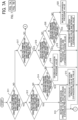
- FIGS. 7A and 7B illustrate a flowchart illustrating control processes for adjusting operating pressure.
- the controller 100 causes the pressure gauge 14 to monitor operating pressure inside the air chamber 5b of the pneumatically driven pump 5.
- the pressure gauge 14 obtains an operating pressure waveform WP illustrated in FIG. 3 .
- the controller 100 monitors a plurality of periods (e.g., three periods according to the embodiment) of the operating pressure waveform WP obtained by the pressure gauge 14.
- the controller 100 detects maximum operating pressure as greatest operating pressure and minimum operating pressure as smallest operating pressure within the plurality of periods.
- step S11 the controller 100 determines if the detected minimum operating pressure is smaller than the lower limit of the minimum operating pressure. If the controller 100 determines that the detected minimum operating pressure is smaller than the lower limit of the minimum operating pressure (YES in step S11), the controller 100 determines if the detected maximum operating pressure is smaller than the lower limit of the maximum operating pressure in step S12. If the controller 100 determines that the detected maximum operating pressure is smaller than the lower limit of the maximum operating pressure (YES in step S12), the controller 100 adjusts a compression pressure value and an expansion pressure value.
- step S13 the controller 100 adds a predetermined additional compression value to a compression pressure value as discharge pressure of compressed air generated by the air compressor 12, that is currently set, thus calculating a new compression pressure value by increasing the compression pressure value that is currently set. Additionally, in step S13, the controller 100 subtracts a predetermined subtraction expansion value from an expansion pressure value as suction pressure of air released by the vacuum pump 13, that is currently set, thus calculating a new expansion pressure value by decreasing the expansion pressure value that is currently set.
- step S12 determines if the detected maximum operating pressure is not smaller than the lower limit of the maximum operating pressure (NO in step S12). If the controller 100 determines if the detected maximum operating pressure is greater than the upper limit of the maximum operating pressure in step S14. If the controller 100 determines that the detected maximum operating pressure is greater than the upper limit of the maximum operating pressure (YES in step S14), the controller 100 decreases the compression pressure value and the expansion pressure value. For example, in step S15, the controller 100 subtracts a predetermined subtraction compression value from the compression pressure value of compressed air, that is currently set. Additionally, in step S15, the controller 100 subtracts the predetermined subtraction expansion value from the expansion pressure value that is currently set.
- the controller 100 determines that the detected maximum operating pressure is not greater than the upper limit of the maximum operating pressure (NO in step S14), the controller 100 determines that the maximum operating pressure is within a target range. Hence, the controller 100 does not adjust the compression pressure value and subtracts the predetermined subtraction expansion value from the expansion pressure value that is currently set in step S 16, thus decreasing the expansion pressure value.
- the controller 100 determines if the detected minimum operating pressure is greater than the upper limit of the minimum operating pressure in step S17. If the controller 100 determines that the detected minimum operating pressure is greater than the upper limit of the minimum operating pressure (YES in step S17), the controller 100 determines if the detected maximum operating pressure is smaller than the lower limit of the maximum operating pressure in step S18. If the controller 100 determines that the detected maximum operating pressure is smaller than the lower limit of the maximum operating pressure (YES in step S18), the controller 100 increases the compression pressure value and the expansion pressure value in step S19. For example, the controller 100 adds the predetermined additional compression value to the compression pressure value that is currently set. Additionally, the controller 100 adds a predetermined additional expansion value to the expansion pressure value that is currently set.
- the controller 100 determines if the detected maximum operating pressure is greater than the upper limit of the maximum operating pressure in step S20. If the controller 100 determines that the detected maximum operating pressure is greater than the upper limit of the maximum operating pressure (YES in step S20), the controller 100 decreases the compression pressure value and increases the expansion pressure value in step S21. For example, the controller 100 subtracts the predetermined subtraction compression value from the compression pressure value that is currently set. Additionally, the controller 100 adds the predetermined additional expansion value to the expansion pressure value that is currently set.
- the controller 100 determines that the detected maximum operating pressure is not greater than the upper limit of the maximum operating pressure (NO in step S20)
- the controller 100 determines that the maximum operating pressure is within the target range. Accordingly, the controller 100 does not adjust the compression pressure value and adds the predetermined additional expansion value to the expansion pressure value that is currently set in step S22, thus increasing the expansion pressure value that is currently set.
- step S17 the controller 100 determines that the minimum operating pressure is within a target range. Accordingly, the controller 100 does not adjust the expansion pressure value.
- step S23 the controller 100 determines if the detected maximum operating pressure is smaller than the lower limit of the maximum operating pressure. If the controller 100 determines that the detected maximum operating pressure is smaller than the lower limit of the maximum operating pressure (YES in step S23), the controller 100 increases the compression pressure value in step S24. For example, the controller 100 adds the additional compression pressure value to the compression pressure value that is currently set.
- the controller 100 determines if the detected maximum operating pressure is not smaller than the lower limit of the maximum operating pressure (NO in step S23). If the controller 100 determines if the maximum operating pressure is greater than the upper limit of the maximum operating pressure in step S25. If the controller 100 determines that the maximum operating pressure is greater than the upper limit of the maximum operating pressure (YES in step S25), the controller 100 decreases the compression pressure value. For example, the controller 100 subtracts the subtraction compression value from the compression pressure value that is currently set in step S26.
- controller 100 determines that the maximum operating pressure is not greater than the upper limit of the maximum operating pressure (NO in step S25)
- the controller 100 determines that each of the minimum operating pressure and the maximum operating pressure is within the target range. Accordingly, the controller 100 does not adjust the compression pressure value and the expansion pressure value.
- the controller 100 controls the vacuum pump 13 to attain the expansion pressure value (e.g., intake pressure) set by the control processes in the flowchart in FIGS. 7A and 7B .
- the controller 100 controls the air compressor 12 to attain the compression pressure value (e.g., the discharge pressure) set by the control processes in the flowchart in FIGS. 7A and 7B .
- the controller 100 determines that the detected minimum operating pressure is smaller than the lower limit of the minimum operating pressure (YES in step S11), as illustrated in steps S13, S15, and S16 in FIGS. 7A and 7B , the controller 100 subtracts the predetermined subtraction expansion value from the expansion pressure value that is currently set, thus decreasing the expansion pressure (e.g., the intake pressure) of the vacuum pump 13. As the expansion pressure (e.g., the intake pressure) decreases, the vacuum pump 13 decreases negative pressure inside the air chamber 5b. The minimum operating pressure increases to a value not smaller than the lower limit of the minimum operating pressure. Accordingly, the controller 100 adjusts the minimum operating pressure to a value between the lower limit and the upper limit of the minimum operating pressure.
- the expansion pressure e.g., the intake pressure
- the controller 100 determines that the detected minimum operating pressure is greater than the upper limit of the minimum operating pressure (YES in step S17), the controller 100 adds the predetermined additional expansion value to the expansion pressure value that is currently set, thus increasing the expansion pressure (e.g., the intake pressure) of the vacuum pump 13 in steps S19, S21, and S22. As the expansion pressure (e.g., the intake pressure) increases, the vacuum pump 13 increases negative pressure inside the air chamber 5b, decreasing the minimum operating pressure to a value not greater than the upper limit of the minimum operating pressure. Accordingly, the controller 100 adjusts the minimum operating pressure to the value between the lower limit and the upper limit of the minimum operating pressure.
- the expansion pressure e.g., the intake pressure
- the controller 100 adjusts the expansion pressure (e.g., the intake pressure) of the vacuum pump 13 so that the minimum operating pressure has the value between the lower limit and the upper limit of the minimum operating pressure.
- the controller 100 retains a constant amount of the toner T sucked by the transport tube 5a.
- the controller 100 determines that the detected maximum operating pressure is smaller than the lower limit of the maximum operating pressure (YES in steps S12, S18, and S23). If the controller 100 determines that the detected maximum operating pressure is smaller than the lower limit of the maximum operating pressure (YES in steps S12, S18, and S23), the controller 100 adds the predetermined additional compression value to the compression pressure value that is currently set.
- the controller 100 controls the air compressor 12 to increase the compression pressure (e.g., the discharge pressure) in steps S13, S19, and S24.
- the compression pressure e.g., the discharge pressure
- the air compressor 12 increases positive pressure inside the air chamber 5b.
- the maximum operating pressure increases to a value not smaller than the lower limit of the maximum operating pressure. Accordingly, the controller 100 adjusts the maximum operating pressure to a value between the lower limit and the upper limit of the maximum operating pressure.
- the controller 100 determines that the detected maximum operating pressure is greater than the upper limit of the maximum operating pressure (YES in steps S14, S20, and S25). If the controller 100 determines that the detected maximum operating pressure is greater than the upper limit of the maximum operating pressure (YES in steps S14, S20, and S25), the controller 100 subtracts the predetermined subtraction compression value from the compression pressure value that is currently set.
- the controller 100 controls the air compressor 12 to decrease the compression pressure (e.g., the discharge pressure) in steps S15, S21, and S26.
- the air compressor 12 decreases positive pressure inside the air chamber 5b, decreasing the maximum operating pressure to a value not greater than the upper limit of the maximum operating pressure. Accordingly, the controller 100 adjusts the maximum operating pressure to the value between the lower limit and the upper limit of the maximum operating pressure.
- the controller 100 adjusts the compression pressure (e.g., the discharge pressure) of the air compressor 12 so that the maximum operating pressure has the value between the lower limit and the upper limit of the maximum operating pressure.
- the controller 100 retains a constant amount of the toner T discharged from the transport tube 5a.
- the controller 100 controls the vacuum pump 13 and the air compressor 12 so that the minimum operating pressure and the maximum operating pressure have the value between the lower limit and the upper limit of the minimum operating pressure and the value between the lower limit and the upper limit of the maximum operating pressure, respectively.
- the controller 100 retains a constant replenishing speed in the precise replenishing mode.
- the replenishing amount of the toner T inside the toner replenishment container 7 is the desired replenishing amount in the precise replenishing mode.
- the controller 100 suppresses variation in the amount of the toner T inside the toner transport tube 6 and the nozzle tube 23 when the pneumatically driven pump 5 stops.
- the controller 100 attains a substantially constant replenishing amount of the toner T that is supplied to the toner replenishment container 7 after the pneumatically driven pump 5 stops.
- the controller 100 adjusts the replenishing amount of the toner T inside the toner replenishment container 7 to the target replenishing amount precisely.
- the controller 100 adds or subtracts the predetermined value to or from the compression pressure value and the expansion pressure value that are currently set.
- the controller 100 may perform other addition and subtraction.
- the controller 100 may calculate a differential value between a detected operating pressure value and a median between a lower limit and an upper limit of operating pressure.
- the controller 100 may calculate a subtraction value or an additional value based on the differential value.
- air e.g., gas
- liquid such as oil
- the pneumatically driven pump 5 may be a diaphragm pump.
- a part of a transport-conveyance path is an elastic thin film. The diaphragm pump applies operating pressure to the thin film, expanding and contracting the transport-conveyance path.
- the toner T is used as powder.
- the powder is not limited to the toner T.
- the powder may be medicine or food ingredients that are powdery or granular.
- a powder replenisher (e.g., the toner replenisher 1) includes a powder storage (e.g., the toner storage tank 2), a powder replenishing container (e.g., the toner replenishment container 7), a pressure adjuster (e.g., the pump driver 10), a positive-displacement pump (e.g., the pneumatically driven pump 5), a powder measuring instrument (e.g., the weighing scale 9), an operating pressure detector (e.g., the pressure gauge 14), a powder conveyance path (e.g., the toner transport tube 6), and a controller (e.g., the controller 100).
- the positive-displacement pump includes a variable capacity portion (e.g., the transport tube 5a).
- the powder storage stores powder (e.g., the toner T).
- the powder replenishment container is replenished with the powder.
- the variable capacity portion has a capacity that is variable.
- the pressure adjuster increases and decreases operating pressure applied to the variable capacity portion and changes the capacity of the variable capacity portion.
- the positive-displacement pump transports the powder as the capacity of the variable capacity portion changes.
- the powder measuring instrument measures an amount (e.g., a weight) of the powder that replenishes the powder replenishment container.
- the operating pressure detector detects the operating pressure applied to the powder conveyance path.
- the controller performs a precise replenishing mode in which, after the controller determines that the powder replenishment container is replenished with the powder in a predetermined amount, while the controller controls the powder measuring instrument to measure the amount of the powder inside the powder replenishment container, the controller controls the pressure adjuster to replenish the powder replenishment container with the powder in a target amount.
- the controller replenishes the powder replenishment container with the powder while the controller controls the pressure adjuster based on a detection result, that is, the detected operating pressure detected by the operating pressure detector.
- the conveying auger when the conveying auger conveys the powder, as the conveying auger rotates, the conveying auger may apply stress such as pressure to the powder, degrading the powder. Additionally, as the conveying auger, that rotates, applies stress such as pressure to the powder, the powder may adhere to each other, generating aggregation that may clog a powder conveyance path and hinder replenishment with the powder.
- the powder replenisher according to the embodiment employs the positive-displacement pump that conveys the powder.
- the positive-displacement pump suppresses stress applied to the powder compared to the conveying auger that conveys the powder.
- the powder replenisher according to the embodiment suppresses degradation and aggregation of the powder inside the powder conveyance path.
- the controller does not interrupt replenishment of the powder replenishment container with the powder immediately after the controller stops the positive-displacement pump. Even after the controller stops the positive-displacement pump, the powder inside the powder conveyance path interposed between the positive-displacement pump and the powder replenishment container is supplied to the powder replenishment container.
- the controller stops the positive-displacement pump.
- the controller calculates the amount of the powder that is smaller than the target amount by subtracting a determined amount of the powder from the target amount of the powder.
- the controller determines the determined amount of the powder by detecting an amount of the powder inside the powder conveyance path interposed between the positive-displacement pump and the powder replenishment container based on a set replenishing speed in the precise replenishing mode.
- the positive-displacement pump may have operating pressure that deviates from target operating pressure due to various factors, destabilizing a replenishing speed (e.g., an amount per unit time) of the powder supplied to the powder replenishment container. Accordingly, when the positive-displacement pump stops, the amount of the powder inside the powder conveyance path interposed between the positive-displacement pump and the powder replenishment container may vary. Consequently, the amount of the powder inside the powder replenishment container may not be the target amount of the powder.
- a replenishing speed e.g., an amount per unit time
- the controller performs the precise replenishing mode after the controller determines that the powder replenishment container is replenished with the powder in the predetermined amount.
- the operating pressure detector detects operating pressure applied to the variable capacity portion. Based on the detected operating pressure, the controller controls the pressure adjuster to replenish the powder replenishment container with the powder. Accordingly, for example, if the controller determines that the operating pressure that is applied to the variable capacity portion and detected by the operating pressure detector is lower than the target operating pressure, the controller controls the pressure adjuster to increase the operating pressure, adjusting the operating pressure applied to the variable capacity portion to the target operating pressure.
- the controller determines that the operating pressure that is applied to the variable capacity portion and detected by the operating pressure detector is higher than the target operating pressure, the controller controls the pressure adjuster to decrease the operating pressure, adjusting the operating pressure applied to the variable capacity portion to the target operating pressure. Accordingly, in the precise replenishing mode, the powder replenisher performs replenishing at the set replenishing speed stably. Consequently, the controller adjusts the amount of the powder supplied to the powder replenishment container to the target amount of the powder precisely.
- the powder replenisher further includes a deaerator (e.g., the degassing pump 20) that degases the powder replenishment container (e.g., the toner replenishment container 7).
- the controller performs an initial replenishing mode (e.g., the high-speed replenishing mode) that replenishes the powder replenishment container with the powder for a predetermined time period while the deaerator degases the powder replenishment container.
- the controller After the controller finishes the initial replenishing mode, in order to replenish the powder replenishment container with the powder in a predetermined amount, the controller performs a deceleration replenishing mode that replenishes the powder replenishment container with the powder at a replenishing speed lower than a replenishing speed in the initial replenishing mode while the controller controls the powder measuring instrument (e.g., the weighing scale 9) to weigh a weight of the powder.
- the controller performs the precise replenishing mode after finishing the deceleration replenishing mode. In the precise replenishing mode, the controller replenishes the powder replenishment container with the powder at a replenishing speed lower than the replenishing speed in the deceleration replenishing mode.
- the powder replenisher shortens a replenishing time period for which the powder is supplied to the powder replenishment container.
- the powder replenisher prevents the powder from overflowing the powder replenishment container (e.g., the toner replenishment container 7).
- the controller adjusts the amount of the powder inside the powder replenishment container to the target amount precisely.
- the controller decreases the replenishing speed for a plurality of times in the deceleration replenishing mode.
- the controller decreases the replenishing speed according to a difference between the amount of the powder inside the powder replenishment container (e.g., the toner replenishment container 7) and the target amount of the powder.
- the controller prevents the powder from overflowing the powder replenishment container due to variation in the replenishing speed and shortens the replenishing time period.
- the controller determines the amount of the powder to be supplied to the powder replenishment container at each of the replenishing speeds in the deceleration replenishing mode based on the amount of the powder supplied to the powder replenishment container in the initial replenishing mode.
- the controller decreases the replenishing speed according to the difference between the amount of the powder inside the powder replenishment container (e.g., the toner replenishment container 7) and the target amount of the powder.
- the controller prevents the powder from overflowing the powder replenishment container and shortens the replenishing time period.
- the controller determines a time period for which the controller performs the initial replenishing mode (e.g., the high-speed replenishing mode) based on an average of the replenishing speeds of a plurality of last times.
- the initial replenishing mode e.g., the high-speed replenishing mode
- the controller suppresses variation in the amount of the powder inside the powder replenishment container (e.g., the toner replenishment container 7).
- the controller controls the pressure adjuster (e.g., the pump driver 10) to retain peak-to-peak operating pressure in a pressure range.
- the pressure adjuster e.g., the pump driver
- the controller retains a constant replenishing speed in the precise replenishing mode.
- the controller adjusts the amount of the powder inside the powder replenishment container to the target amount precisely.
- a powder replenishing method replenishes the powder replenishment container (e.g., the toner replenishment container 7) with powder (e.g., the toner T) stored in the powder storage (e.g., the toner storage tank 2).
- the variable capacity portion e.g., the transport tube 5a
- the pressure adjuster e.g., the pump driver 10) increases and decreases operating pressure applied to the variable capacity portion, changing the capacity of the variable capacity portion.
- the positive-displacement pump e.g., the pneumatically driven pump 5 transports the powder as the capacity of the variable capacity portion changes.
- the controller performs a precise replenishing mode in which, after the controller determines that the powder replenishment container is replenished with the powder in a predetermined amount, while the controller controls the powder measuring instrument (e.g., the weighing scale 9) to measure an amount of the powder inside the powder replenishment container, the controller replenishes the powder replenishment container with the powder in a target amount.
- the operating pressure detector e.g., the pressure gauge 14
- the controller controls the pressure adjuster based on the operating pressure detected by the operating pressure detector, the controller replenishes the powder replenishment container with the powder.
- the controller suppresses stress applied to the powder and replenishes the powder replenishment container with the powder in the target amount precisely.
Landscapes
- Engineering & Computer Science (AREA)
- Physics & Mathematics (AREA)
- General Physics & Mathematics (AREA)
- Mechanical Engineering (AREA)
- Quality & Reliability (AREA)
- Life Sciences & Earth Sciences (AREA)
- Sustainable Development (AREA)
- Dry Development In Electrophotography (AREA)
- Basic Packing Technique (AREA)
- Weight Measurement For Supplying Or Discharging Of Specified Amounts Of Material (AREA)
Abstract
Description
- Embodiments of this disclosure relate to a powder replenisher and a powder replenishing method.
- Related-art powder replenishers include a powder storage and a powder replenishment container. The powder storage stores powder. The powder replenishment container is replenished with the powder sent from the powder storage.
-
Japanese Patent No. 4860777 - However, while the controller reduces stress applied to the powder, the controller may not adjust the amount of the powder inside the weighing container to the target amount precisely.
- It is a general object of the present disclosure to provide an improved and useful powder replenisher in which the above-mentioned problems are eliminated. In order to achieve the above-mentioned object, there is provided the powder replenisher according to
claim 1. Advantageous embodiments are defined by the dependent claims. - Advantageously, the powder replenisher includes a powder storage that stores powder. A powder replenishment container is replenished with the powder. A variable capacity portion has a capacity that is variable. A pressure adjuster increases and decreases operating pressure applied to the variable capacity portion. The pressure adjuster changes the capacity of the variable capacity portion to transport the powder. A powder measuring instrument measures an amount of the powder that replenishes the powder replenishment container. An operating pressure detector detects the operating pressure. A controller is operatively connected to the pressure adjuster, the powder measuring instrument, and the operating pressure detector. The controller performs a precise replenishing mode in which, after the controller determines that the powder replenishment container is replenished with the powder in a predetermined amount, while the controller controls the powder measuring instrument to measure the amount of the powder inside the powder replenishment container, the controller controls the pressure adjuster to replenish the powder replenishment container with the powder in a target amount. The controller controls the pressure adjuster to replenish the powder replenishment container with the powder while the controller controls the pressure adjuster based on the operating pressure detected by the operating pressure detector in the precise replenishing mode.
- It is another object of the present disclosure to provide an improved and useful powder replenishing method in which the above-mentioned problems are eliminated.
- Advantageously, the powder replenishing method includes storing powder in a powder storage, controlling a pressure adjuster to increase and decrease operating pressure applied to a variable capacity portion, changing a capacity of the variable capacity portion to transport the powder to a powder replenishment container, determining that the powder replenishment container is replenished with the powder in a predetermined amount, starting a precise replenishing mode, measuring an amount of the powder inside the powder replenishment container, detecting the operating pressure applied to the variable capacity portion, controlling the pressure adjuster based on the detected operating pressure, and controlling the pressure adjuster to replenish the powder replenishment container with the powder in a target amount.
- Accordingly, the controller suppresses stress applied to the powder and replenishes the powder replenishment container with the powder in the target amount precisely.
- A more complete appreciation of embodiments of the present disclosure and many of the attendant advantages and features thereof can be readily obtained and understood from the following detailed description with reference to the accompanying drawings, wherein:
-
FIG. 1 is a schematic diagram of a toner replenisher according to an embodiment of the present disclosure; -
FIG. 2A is a diagram of a pneumatically driven pump and a solenoid valve incorporated in the toner replenisher depicted inFIG. 1 when the solenoid valve is turned off; -
FIG. 2B is a diagram of the pneumatically driven pump and the solenoid valve depicted inFIG. 2A when the solenoid valve is turned on; -
FIG. 3 is a diagram of a waveform of operating pressure as one example; -
FIG. 4 is a block diagram of the toner replenisher depicted inFIG. 1 , illustrating a controller that controls replenishing a toner replenishment container incorporated in the toner replenisher depicted inFIG. 1 with toner; -
FIG. 5 is a graph illustrating a relation between a time period and a replenishing amount of the toner supplied to the toner replenishment container while the controller depicted inFIG. 4 controls replenishing the toner replenishment container with the toner; -
FIG. 6 is a flowchart illustrating control processes in a deceleration replenishing mode performed by the controller depicted inFIG. 4 ; -
FIG. 7A is a part of a flowchart illustrating control processes for adjusting operating pressure, that are performed by the controller depicted inFIG. 4 ; and -
FIG. 7B is another part of the flowchart illustrating the control processes for adjusting operating pressure, that are performed by the controller depicted inFIG. 4 . - The accompanying drawings are intended to depict embodiments of the present disclosure and should not be interpreted to limit the scope thereof. The accompanying drawings are not to be considered as drawn to scale unless explicitly noted. Also, identical or similar reference numerals designate identical or similar components throughout the several views.
- In describing embodiments illustrated in the drawings, specific terminology is employed for the sake of clarity. However, the disclosure of this specification is not intended to be limited to the specific terminology so selected and it is to be understood that each specific element includes all technical equivalents that have a similar function, operate in a similar manner, and achieve a similar result.
- Referring now to the drawings, embodiments of the present disclosure are described below. As used herein, the singular forms "a," "an," and "the" are intended to include the plural forms as well, unless the context clearly indicates otherwise.
- A description is provided of a construction of a
toner replenisher 1 serving as a powder replenisher according to an embodiment of the present disclosure. -
FIG. 1 is a schematic diagram of thetoner replenisher 1 according to the embodiment. - The
toner replenisher 1 according to the embodiment includes atoner storage tank 2 and a toner replenishment container 7. Thetoner storage tank 2 serves as a powder storage that stores toner T serving as powder. The toner replenishment container 7 serves as a powder replenishment container that is replenished with the toner T. Thetoner replenisher 1 further includes a pneumatically drivenpump 5 serving as a positive-displacement pump that transports the toner T from thetoner storage tank 2 to the toner replenishment container 7. Thetoner replenisher 1 further includes a weighingscale 9 serving as a powder measuring instrument that measures an amount of the toner T replenishing the toner replenishment container 7. Theweighing scale 9 is a load cell indicator including a weighing indicator W. - The
toner storage tank 2 accommodates atoner injector tube 2a. Thetoner replenisher 1 further includes atoner suction tube 4. One end of thetoner suction tube 4 is disposed inside thetoner injector tube 2a. Another end of thetoner suction tube 4 is coupled with the pneumatically drivenpump 5. Thetoner replenisher 1 further includes atoner transport tube 6. One end of thetoner transport tube 6 is coupled with the pneumatically drivenpump 5. Another end of thetoner transport tube 6 is coupled with atoner discharger 22 that discharges the toner T to the toner replenishment container 7. - The
toner discharger 22 includes anozzle tube 23 having a tip that is coupled with anozzle 8. Thetoner replenisher 1 further includes anozzle elevator 21 that lifts and lowers thetoner discharger 22 in a direction X. Thetoner discharger 22 further includes adegassing pump 20 serving as a deaerator that removes air from the toner replenishment container 7. - The
nozzle tube 23 has a double tube structure constructed of an inner tube and an outer tube. The inner tube receives the toner T transported from thetoner transport tube 6. The outer tube receives air inside the toner replenishment container 7 sucked by thedegassing pump 20. - The
toner storage tank 2 includes a bottom that mounts a fluidization portion 3 that fluidizes the toner T. The fluidization portion 3 includes a ventilation plate and an air intake path. The ventilation plate includes a plurality of micropores that ejects air. The micropore has a size smaller than a particle size (e.g., a particle diameter) of the toner T. The air intake path sends air to the micropores of the ventilation plate. The fluidization portion 3 is coupled with afluidization air supply 30. Thefluidization air supply 30 sends air to the air intake path of the fluidization portion 3. The micropores of the ventilation plate eject air that fluidizes the toner T inside thetoner storage tank 2. Thefluidization air supply 30 that sends air to the air intake path of the fluidization portion 3 is an air compressor, a fan, a blower, or the like. - The pneumatically driven
pump 5 is the positive-displacement pump that includes atransport tube 5a and anair chamber 5b. Thetransport tube 5a serves as a variable capacity portion that shrinks and expands by operating pressure. Theair chamber 5b accommodates thetransport tube 5a and applies operating pressure to thetransport tube 5a. Thetransport tube 5a has both ends that mount check valves, respectively, that prevent the toner T from flowing backward. - The
toner replenisher 1 further includes apump driver 10 serving as a pressure adjuster or a pressure increasing-decreasing portion that intakes and exhausts air inside theair chamber 5b of the pneumatically drivenpump 5 and changes pressure inside theair chamber 5b, thus driving the pneumatically drivenpump 5. Thepump driver 10 includes a 3-port solenoid valve 11 serving as a directional control valve, anair compressor 12, and avacuum pump 13. Theair compressor 12 sends compressed air into theair chamber 5b. Thevacuum pump 13 releases air from theair chamber 5b. -
FIGS. 2A and 2B illustrate driving of the pneumatically drivenpump 5. - As illustrated in
FIG. 2A , when thesolenoid valve 11 is turned off, thesolenoid valve 11 blocks airflow from thevacuum pump 13 and releases airflow from theair compressor 12, sending compressed air into theair chamber 5b of the pneumatically drivenpump 5. Accordingly, positive pressure inside theair chamber 5b increases, shrinking thetransport tube 5a. Consequently, the toner T inside thetransport tube 5a is discharged and transported into thetoner transport tube 6. - As illustrated in
FIG. 2B , when thesolenoid valve 11 is turned on, thesolenoid valve 11 blocks airflow from theair compressor 12 and releases airflow from thevacuum pump 13. Thevacuum pump 13 deflates theair chamber 5b. Accordingly, theair chamber 5b has negative pressure that expands thetransport tube 5a. Consequently, thetransport tube 5a sucks the toner T from thetoner storage tank 2, transporting the toner T through thetoner suction tube 4 to thetransport tube 5a. - Since the pneumatically driven
pump 5 transports the toner T, compared to a conveying auger (e.g., a screw auger) that transports the toner T, the pneumatically drivenpump 5 decreases stress such as pressure imposed on the toner T. Accordingly, the pneumatically drivenpump 5 prevents an external additive to the toner T from being separated from or buried into a surface of the toner T, causing the external additive to achieve a target advantage. Additionally, the pneumatically drivenpump 5 prevents toner particles of the toner T from adhering to each other, suppressing aggregation of the toner particles. - As the
solenoid valve 11 is turned on and off, as illustrated inFIG. 3 , thesolenoid valve 11 changes operating pressure inside theair chamber 5b. Accordingly, thetransport tube 5a shrinks and expands repeatedly, transporting the toner T from thetoner storage tank 2 to the toner replenishment container 7 continuously. As a switching speed at which thesolenoid valve 11 is turned on and off is changed, a replenishing speed at which the toner replenishment container 7 is replenished with the toner T is switched. For example, the replenishing speed defines a replenishing amount of the toner T per unit time in which the toner replenishment container 7 is replenished with the toner T. - According to the embodiment, as illustrated in
FIG. 1 , thetoner replenisher 1 further includes a pressure gauge 14 (e.g., a pressure indicator (PI)) serving as an operating pressure detector that is disposed in an air channel interposed between thesolenoid valve 11 and the pneumatically drivenpump 5. Thepressure gauge 14 detects pressure (e.g., operating pressure) inside theair chamber 5b. Based on the pressure detected by thepressure gauge 14, acontroller 100 illustrated inFIG. 4 controls theair compressor 12 and thevacuum pump 13. - For example, as illustrated in
FIG. 3 , thecontroller 100 controls theair compressor 12 such that maximum operating pressure inside theair chamber 5b is greater than a lower limit of the maximum operating pressure and smaller than an upper limit of the maximum operating pressure. Thecontroller 100 controls thevacuum pump 13 such that minimum operating pressure inside theair chamber 5b is greater than a lower limit of the minimum operating pressure and smaller than an upper limit of the minimum operating pressure. -
FIG. 4 is a block diagram of thetoner replenisher 1, illustrating a control system that controls operations for replenishment with the toner T. - As illustrated in
FIG. 4 , thecontroller 100 includes a central processing unit (CPU), a random access memory (RAM), a read only memory (ROM), and a flash memory. Thecontroller 100 controls driving of various devices of thetoner replenisher 1 and performs various arithmetic processing. Thecontroller 100 is electrically connected to thenozzle elevator 21, thedegassing pump 20, thefluidization air supply 30, the weighingscale 9, atimer 101, thepressure gauge 14, thesolenoid valve 11, theair compressor 12, thevacuum pump 13, and the like. -
FIG. 5 is a graph illustrating a relation between a replenishing amount and a replenishing time period of the toner T that replenishes the toner replenishment container 7 while thetoner replenisher 1 performs replenishing of the toner T. -
FIG. 5 illustrates a case in which the toner replenishment container 7 is replenished with the toner T in a replenishing amount of 190 g.FIG. 5 illustrates phases P1, P2, and P3. In the phase P1, the toner T in a replenishing amount up to approximately 185 g is supplied to the toner replenishment container 7 quickly. In the phase P3, after the toner replenishment container 7 is replenished with the toner T in the replenishing amount of approximately 185 g, the toner T in a replenishing amount up to a target replenishing amount of 190 g is supplied to the toner replenishment container 7 precisely. In the phase P2 after the toner replenishment container 7 is replenished with the toner T in a replenishing amount of approximately 170 g, the toner T is supplied carefully to prevent the toner replenishment container 7 from overflowing with the toner T due to variation in the replenishing speed and the like. - According to the embodiment, in order to supply the toner T to the toner replenishment container 7 quickly and precisely without overflowing, the
toner replenisher 1 has a high-speed replenishing mode serving as an initial replenishing mode, a deceleration replenishing mode, and a precise replenishing mode. The high-speed replenishing mode defines degassing replenishing that replenishes the toner replenishment container 7 with the toner T while thedegassing pump 20 removes air from the toner replenishment container 7. InFIG. 5 , M1 indicates the high-speed replenishing mode, as time-based replenishing, in which thecontroller 100 controls thedegassing pump 20 to degas the toner replenishment container 7. M2 indicates the deceleration replenishing mode as amount-based replenishing. M3 indicates the precise replenishing mode, as amount-based replenishing, in which thecontroller 100 controls thepump driver 10 to adjust operating pressure. - As replenishment with the toner T starts, the
controller 100 drives thefluidization air supply 30 that fluidizes the toner T inside thetoner storage tank 2 with air. Thecontroller 100 turns on or off thesolenoid valve 11 at a high speed and drives theair compressor 12 and thevacuum pump 13. - As the switching speed at which the
controller 100 switches turning on and off of thesolenoid valve 11 changes, a cycle for changing positive pressure and negative pressure of operating pressure periodically inside theair chamber 5b of the pneumatically drivenpump 5 changes. Accordingly, a discharge amount per unit time of the toner T discharged from the pneumatically drivenpump 5 changes, thus changing the replenishing speed of the toner T. According to the embodiment, in the high-speed replenishing mode, thecontroller 100 switches turning on and off of thesolenoid valve 11 at a high switching speed, replenishing the toner replenishment container 7 with the toner T at a high replenishing speed of the toner T. In the deceleration replenishing mode, thecontroller 100 switches turning on and off of thesolenoid valve 11 at a low switching speed that is lower than the high switching speed in the high-speed replenishing mode, replenishing the toner replenishment container 7 with the toner T at a low replenishing speed of the toner T, that is lower than the high replenishing speed in the high-speed replenishing mode. In the precise replenishing mode, thecontroller 100 switches turning on and off of thesolenoid valve 11 at a low switching speed that is lower than the low switching speed in the deceleration replenishing mode, replenishing the toner replenishment container 7 with the toner T at a low replenishing speed of the toner T, that is lower than the low replenishing speed in the deceleration replenishing mode. - In the high-speed replenishing mode, the weighing
scale 9 does not weigh the replenishing amount of the toner T that replenishes the toner replenishment container 7. The toner T is supplied to the toner replenishment container 7 until a target time measured by thetimer 101. With degassing replenishing, thedegassing pump 20 intakes air and sucks up the toner T inside the toner replenishment container 7. Hence, the weighingscale 9 does not weigh the replenishing amount of the toner T inside the toner replenishment container 7 precisely. Accordingly, if thetoner replenisher 1 replenishes the toner replenishment container 7 with the toner T in the high-speed replenishing mode until the replenishing amount of the toner T inside the toner replenishment container 7, that is weighed by the weighingscale 9, reaches a desired replenishing amount, at worst, the toner T may overflow the toner replenishment container 7. In order to prevent the toner T from overflowing the toner replenishment container 7, if thecontroller 100 decreases the desired replenishing amount in the high-speed replenishing mode, a time period used in the deceleration replenishing mode may increase, resulting in an increased replenishing time period. Hence, in the high-speed replenishing mode that performs degassing replenishing, thecontroller 100 does not control the weighingscale 9 to weigh the replenishing amount of the toner T, thus replenishing the toner replenishment container 7 with the toner T. - However, if operating pressure inside the
air chamber 5b of the pneumatically drivenpump 5 changes, for example, the discharge amount of the toner T discharged from the pneumatically drivenpump 5 changes. Accordingly, the replenishing speed of the toner T (e.g., the replenishing amount of the toner T per unit time) changes. As the replenishing speed of the toner T increases, variation in the replenishing speed of the toner T increases. Accordingly, when the toner T is supplied to the toner replenishment container 7 for the target time period in the high-speed replenishing mode in which the toner T is supplied to the toner replenishment container 7 at a high speed, variation in the replenishing amount of the toner T inside the toner replenishment container 7 may increase. - To address the circumstances described above, according to the embodiment, in order to suppress variation in the replenishing amount of the toner T inside the toner replenishment container 7 when the toner T is supplied to the toner replenishment container 7 for the target time period, the
controller 100 determines the target time period based on an average of last three replenishing speeds of the toner T in the high-speed replenishing mode. For example, thecontroller 100 includes a nonvolatile memory that stores the last three replenishing speeds of the toner T in the high-speed replenishing mode. When the high-speed replenishing mode finishes as the toner T is supplied to the toner replenishment container 7 for the target time period, thecontroller 100 stops thedegassing pump 20 and controls thenozzle elevator 21 to lift thenozzle 8 so that thenozzle 8 is situated above the toner T inside the toner replenishment container 7. Subsequently, thecontroller 100 calculates a replenishing speed of the toner T based on a replenishing amount of the toner T inside the toner replenishment container 7, that is weighed by the weighingscale 9, and an instant target time period. Thecontroller 100 deletes an oldest replenishing speed of the toner T of the last three replenishing speeds of the toner T in the high-speed replenishing mode, that are stored in the nonvolatile memory. Thecontroller 100 controls the nonvolatile memory to store the calculated replenishing speed of the toner T. When thecontroller 100 performs the high-speed replenishing mode, thecontroller 100 calculates the average of the last three replenishing speeds of the toner T in the high-speed replenishing mode, that are stored in the nonvolatile memory. Thecontroller 100 calculates the target time period based on the calculated average and the desired replenishing amount of the toner T in the high-speed replenishing mode. - As described above, in order to calculate the target time period, the
controller 100 uses the average of the last three replenishing speeds of the toner T in the high-speed replenishing mode. Alternatively, thecontroller 100 may use last four or more data to calculate the average. - As described above, the
controller 100 determines the target time period in the high-speed replenishing mode by using the average of the plurality of last replenishing speeds of the toner T in the high-speed replenishing mode. Hence, even if the replenishing speed of the toner T changes, the target time period changes automatically. Accordingly, thecontroller 100 suppresses variation in the replenishing amount of the toner T in the high-speed replenishing mode with respect to the desired replenishing amount. Consequently, thecontroller 100 prevents the replenishing amount of the toner T in the high-speed replenishing mode from decreasing from the desired replenishing amount excessively, prevents the subsequent, deceleration replenishing mode from extending, and prevents the replenishing time period of the toner T from extending. Additionally, thecontroller 100 prevents the replenishing amount of the toner T in the high-speed replenishing mode from increasing from the desired replenishing amount of the toner T excessively and prevents the toner T from overflowing the toner replenishment container 7. - When the high-speed replenishing mode finishes, the
controller 100 performs the deceleration replenishing mode in which the replenishing speed of the toner T (e.g., the switching speed of the solenoid valve 11) is lower than the replenishing speed of the toner T in the high-speed replenishing mode. The deceleration replenishing mode performs weighing replenishing that does not degas and supplies the toner T while the weighingscale 9 weighs the replenishing amount of the toner T inside the toner replenishment container 7. Since the deceleration replenishing mode does not degas, the weighingscale 9 weighs the replenishing amount of the toner T inside the toner replenishment container 7 precisely. Thus, thecontroller 100 replenishes the toner replenishment container 7 with the toner T in a predetermined amount precisely. - Since the
controller 100 decreases the replenishing speed of the toner T in the deceleration replenishing mode compared to the high-speed replenishing mode, thecontroller 100 suppresses variation in the replenishing amount of the toner T, that is caused by change in the replenishing speed of the toner T. Hence, thecontroller 100 prevents the toner T in a replenishing amount greater than the target replenishing amount from being supplied to the toner replenishment container 7 and prevents the toner T from overflowing the toner replenishment container 7. In the deceleration replenishing mode, thecontroller 100 decreases the replenishing speed of the toner T stepwise three times, that is, a first deceleration time N1, a second deceleration time N2, and a third deceleration time N3 illustrated inFIG. 5 , preventing the toner T from overflowing the toner replenishment container 7. Thus, thecontroller 100 replenishes the toner replenishment container 7 with the toner T in the predetermined amount early. At the third deceleration time N3 at which thecontroller 100 decreases the replenishing speed of the toner T, thecontroller 100 supplies the toner T to the toner replenishment container 7 at a replenishing speed that is decreased sufficiently, thus replenishing the toner replenishment container 7 with the toner T precisely to some extent. Accordingly, as illustrated inFIG. 5 , thecontroller 100 performs the deceleration replenishing mode until the toner replenishment container 7 is replenished with the toner T in a replenishing amount that is not smaller than a replenishing amount of the toner T with which thecontroller 100 starts the precise replenishing mode. Hence, thecontroller 100 shortens a time period of the precise replenishing mode, shortening the replenishing time period of the toner T. -
FIG. 6 is a flowchart of control processes of the deceleration replenishing mode. - As described above, when the
controller 100 finishes the high-speed replenishing mode, thecontroller 100 stops thedegassing pump 20, controls thenozzle elevator 21 to lift thenozzle 8 so that thenozzle 8 is situated above the toner T inside the toner replenishment container 7. Subsequently, thecontroller 100 controls the weighingscale 9 to weigh the replenishing amount of the toner T in the high-speed replenishing mode. Subsequently, thecontroller 100 reads initial parameters from the nonvolatile memory and calculates a replenishing amount of the toner T at a decreased replenishing speed and the like based on the calculated replenishing amount of the toner T in step S1. - As illustrated in
FIG. 6 , thecontroller 100 sets the initial parameters in step S1. The initial parameters include a first parameter, a second parameter, a third parameter, a fourth parameter, a fifth parameter, a sixth parameter, and a seventh parameter. As the first parameter, a number of deceleration times is three. Whenever thecontroller 100 changes the replenishing speed of the toner T (e.g., the switching speed of the solenoid valve 11), thecontroller 100 decrements the number of deceleration times. The switching speed defines a speed for switching turning on and off of thesolenoid valve 11. As thecontroller 100 changes the switching speed of thesolenoid valve 11, the cycle for changing positive pressure and negative pressure of operating pressure periodically inside theair chamber 5b of the pneumatically drivenpump 5 changes. Accordingly, the discharge amount per unit time of the toner T discharged from the pneumatically drivenpump 5 changes, thus changing the replenishing speed of the toner T. - The switching speed at the first deceleration time N1 at which the
controller 100 decreases the replenishing speed of the toner T as the second parameter defines a switching speed at an initial deceleration, that is, the first deceleration time N1. At the second deceleration time N2 at which thecontroller 100 decreases the replenishing speed of the toner T, thecontroller 100 changes the switching speed to a decreased switching speed that is lower than the switching speed applied at the first deceleration time N1. At the third deceleration time N3 at which thecontroller 100 decreases the replenishing speed of the toner T, thecontroller 100 changes the switching speed to a decreased switching speed that is lower than the decreased switching speed applied at the second deceleration time N2. Thecontroller 100 calculates the decreased switching speed at the second deceleration time N2 by subtracting a deceleration value from the switching speed at the first deceleration time N1. The deceleration value, as the third parameter, is calculated by a formula (1) below.
- In the formula (1), Dv represents the deceleration value. Is represents the switching speed at the initial deceleration, that is, the first deceleration time N1. Ps represents the switching speed in the precise replenishing mode. The
controller 100 calculates the decreased switching speed at the third deceleration time N3 by subtracting the deceleration value from the decreased switching speed at the second deceleration time N2. - The replenishing amount at the decreased switching speed as the fourth parameter defines the replenishing amount of the toner T in the deceleration replenishing mode. The
controller 100 calculates the replenishing amount at the decreased switching speed by subtracting the replenishing amount of the toner T in the high-speed replenishing mode from a commencement replenishing amount before the precise replenishing mode, that is, a replenishing amount of the toner T when the deceleration replenishing mode finishes. - The
controller 100 calculates an additional weight, as the fifth parameter, by dividing the calculated replenishing amount at the decreased switching speed by 14. Thecontroller 100 calculates an additional value, as the sixth parameter, according to a formula (2) below.
- In the formula (2), Av represents the additional value. N represents the number of deceleration times. Aw represents the additional weight. As described above, the number of deceleration times is three at the first deceleration time N1, two at the second deceleration time N2, and one at the third deceleration time N3. Hence, as indicated by the formula (2) that calculates the additional value, as the number of deceleration times increases, the additional value decreases.
- The
controller 100 calculates a desired replenishing amount as the seventh parameter. The desired replenishing amount defines a target replenishing amount set for each time for decreasing the replenishing speed. In step S2, thecontroller 100 determines if a current replenishing amount of the toner T is not smaller than the desired replenishing amount. If thecontroller 100 determines that the current replenishing amount of the toner T is not smaller than the desired replenishing amount (NO in step S2), thecontroller 100 switches the switching speed. At the first deceleration time N1 at which thecontroller 100 decreases the replenishing speed of the toner T, thecontroller 100 calculates the desired replenishing amount by adding the additional value described above to the replenishing amount in the high-speed replenishing mode. At the second deceleration time N2 at which thecontroller 100 decreases the replenishing speed of the toner T, thecontroller 100 calculates the desired replenishing amount by adding the additional value to the desired replenishing amount at the first deceleration time N1. At the third deceleration time N3 at which thecontroller 100 decreases the replenishing speed of the toner T, thecontroller 100 calculates the desired replenishing amount by adding the additional value to the desired replenishing amount at the second deceleration time N2. The desired replenishing amount at the third deceleration time N3 is equivalent to the commencement replenishing amount before the precise replenishing mode. - After the
controller 100 sets the initial parameters for the first deceleration time N1, thecontroller 100 switches thesolenoid valve 11 at the switching speed at the initial deceleration, thus supplying the toner T at the first deceleration time N1 at the replenishing speed of the toner T that is lower than the replenishing speed of the toner T in the high-speed replenishing mode. - If the
controller 100 determines that the current replenishing amount of the toner T inside the toner replenishment container 7, that is weighed by the weighingscale 9, is not smaller than the desired replenishing amount at the first deceleration time N1 (NO in step S2), thecontroller 100 determines if the current replenishing amount of the toner T inside the toner replenishment container 7 is not smaller than the commencement replenishing amount before the precise replenishing mode in step S3. If thecontroller 100 determines that the current replenishing amount of the toner T inside the toner replenishment container 7 is smaller than the commencement replenishing amount before the precise replenishing mode (YES in step S3), thecontroller 100 changes four parameters, that is, an eighth parameter, a ninth parameter, a tenth parameter, and an eleventh parameter, described below in step S4. The eighth parameter defines a number of deceleration times for decreasing the replenishing speed of the toner T. The ninth parameter defines a switching speed of thesolenoid valve 11. The tenth parameter defines an additional value. The eleventh parameter defines a desired replenishing amount of the toner T. - For example, the
controller 100 decrements the number of deceleration times from three to two. Thecontroller 100 changes the switching speed of thesolenoid valve 11 to a switching speed at the second deceleration time N2 obtained by subtracting the deceleration value from the switching speed at the initial deceleration (e.g., the first deceleration time N1) as the current switching speed. Thecontroller 100 recalculates the additional value. Thecontroller 100 adds the recalculated additional value to the desired replenishing amount at the first deceleration time N1, calculating a desired replenishing amount at the second deceleration time N2. Thecontroller 100 switches turning on and off of thesolenoid valve 11 at the switching speed at the second deceleration time N2, that is changed. Thus, thecontroller 100 performs replenishing at the second deceleration time N2 at a replenishing speed of the toner T, that is lower than the replenishing speed of the toner T at the first deceleration time N1. - If the
controller 100 determines that the current replenishing amount of the toner T inside the toner replenishment container 7, that is weighed by the weighingscale 9, is not smaller than the desired replenishing amount at the second deceleration time N2 (NO in step S2), thecontroller 100 determines if the current replenishing amount of the toner T inside the toner replenishment container 7 is smaller than the commencement replenishing amount before the precise replenishing mode. If thecontroller 100 determines that the current replenishing amount of the toner T inside the toner replenishment container 7 is smaller than the commencement replenishing amount before the precise replenishing mode (YES in step S3), thecontroller 100 changes the parameters as described above in step S4. That is, thecontroller 100 changes the switching speed of thesolenoid valve 11 to a switching speed at the third deceleration time N3 obtained by subtracting the deceleration value from the switching speed at the second deceleration time N2 as the current switching speed. Thecontroller 100 decrements the number of deceleration times from two to one. Thecontroller 100 recalculates the additional value. Thecontroller 100 adds the additional value to the desired replenishing amount at the second deceleration time N2, thus calculating a desired replenishing amount at the third deceleration time N3. As described above, the desired replenishing amount at the third deceleration time N3 is equivalent to the commencement replenishing amount before the precise replenishing mode. - The
controller 100 switches turning on and off of thesolenoid valve 11 at the changed switching speed at the third deceleration time N3, thus performing replenishment at the third deceleration time N3 at the replenishing speed of the toner T, that is lower than the replenishing speed at the second deceleration time N2. At the third deceleration time N3, the desired replenishing amount is equivalent to the commencement replenishing amount before the precise replenishing mode. Hence, if thecontroller 100 determines that the current replenishing amount of the toner T inside the toner replenishment container 7, that is weighed by the weighingscale 9, is not smaller than the desired replenishing amount at the third deceleration time N3 (NO in step S2), thecontroller 100 determines that the current replenishing amount of the toner T is not smaller than the commencement replenishing amount before the precise replenishing mode (NO in step S3). Thus, thecontroller 100 finishes the deceleration replenishing mode and starts the precise replenishing mode. - At the first deceleration time N1 and the second deceleration time N2 also, if the
controller 100 determines that the current replenishing amount of the toner T, that is weighed by the weighingscale 9, is not smaller than the commencement replenishing amount before the precise replenishing mode (NO in step S3), thecontroller 100 finishes the deceleration replenishing mode and starts the precise replenishing mode. - In the precise replenishing mode, the
controller 100 decreases the switching speed of thesolenoid valve 11 to a switching speed that is even lower than the switching speed at the third deceleration time N3, thus performing replenishing at a decreased replenishing speed. In the precise replenishing mode also, thecontroller 100 does not cause thedegassing pump 20 to degas and causes the weighingscale 9 to weigh the replenishing amount of the toner T inside the toner replenishment container 7, thus performing weighing replenishing. - As illustrated in
FIG. 5 , the weighingscale 9 performs final weighing when several seconds elapse after thecontroller 100 finishes the precise replenishing mode. Even after the precise replenishing mode finishes and the pneumatically drivenpump 5 stops, the toner T inside thetoner transport tube 6 and thenozzle tube 23 moves to the toner replenishment container 7. Thus, the toner replenishment container 7 is replenished with the toner T. Hence, the weighingscale 9 may not weigh the toner T stably, immediately after the precise replenishing mode finishes. To address the circumstance, after the toner T inside thetoner transport tube 6 and thenozzle tube 23 falls into the toner replenishment container 7 so that the weighingscale 9 weighs the toner T stably, the weighingscale 9 performs final weighing. Thecontroller 100 performs final determination that the toner T inside the toner replenishment container 7 attains a replenishing amount within an error of the target replenishing amount. - As described above, even after the pneumatically driven
pump 5 stops, the toner T is supplied to the toner replenishment container 7. Hence, the desired replenishing amount in the precise replenishing mode is slightly smaller than the target replenishing amount. For example, the desired replenishing amount in the precise replenishing mode is set as described below. Based on the replenishing speed set in the precise replenishing mode, thecontroller 100 determines an amount of the toner T inside thetoner transport tube 6 and thenozzle tube 23 when the pneumatically drivenpump 5 stops. Thecontroller 100 subtracts the determined amount of the toner T inside thetoner transport tube 6 and thenozzle tube 23 from the target replenishing amount, obtaining the desired replenishing amount in the precise replenishing mode. - However, the pneumatically driven
pump 5 may have operating pressure that deviates from target operating pressure due to various factors. The pneumatically drivenpump 5 may have an uneven discharge amount and an unstable replenishing speed. If the toner T inside thetransport tube 5a of the pneumatically drivenpump 5 has a toner density that varies, the operating pressure also varies. If the toner T inside thetransport tube 5a has the toner density that varies, the discharge amount of the pneumatically drivenpump 5 also varies. - As described above, variation in operating pressure destabilizes the replenishing speed. Hence, when the pneumatically driven
pump 5 stops, the amount of the toner T inside thetoner transport tube 6 and thenozzle tube 23 varies. Accordingly, after the precise replenishing mode finishes and the pneumatically drivenpump 5 stops, the amount of the toner T supplied to the toner replenishment container 7 varies. The replenishing amount of the toner T inside the toner replenishment container 7 may deviate from the error of the target replenishing amount. Thus, the weighingscale 9 may perform faulty final weighing. - To address the circumstances, according to the embodiment, in the precise replenishing mode, based on pressure (e.g., operating pressure) inside the
air chamber 5b, that is measured with thepressure gauge 14, thecontroller 100 performs feedback control on theair compressor 12 and thevacuum pump 13. For example, in order to adjust maximum operating pressure and minimum operating pressure inside theair chamber 5b of the pneumatically drivenpump 5 within a range between the lower limit and the upper limit of the maximum operating pressure and a range between the lower limit and the upper limit of the minimum operation pressure illustrated inFIG. 3 , respectively, thecontroller 100 controls theair compressor 12 and thevacuum pump 13, retaining constant peak-to-peak operating pressure. -
FIGS. 7A and7B illustrate a flowchart illustrating control processes for adjusting operating pressure. - When the precise replenishing mode starts, the
controller 100 causes thepressure gauge 14 to monitor operating pressure inside theair chamber 5b of the pneumatically drivenpump 5. Thepressure gauge 14 obtains an operating pressure waveform WP illustrated inFIG. 3 . Thecontroller 100 monitors a plurality of periods (e.g., three periods according to the embodiment) of the operating pressure waveform WP obtained by thepressure gauge 14. Thecontroller 100 detects maximum operating pressure as greatest operating pressure and minimum operating pressure as smallest operating pressure within the plurality of periods. - As illustrated in
FIGS. 7A and7B , in step S11, thecontroller 100 determines if the detected minimum operating pressure is smaller than the lower limit of the minimum operating pressure. If thecontroller 100 determines that the detected minimum operating pressure is smaller than the lower limit of the minimum operating pressure (YES in step S11), thecontroller 100 determines if the detected maximum operating pressure is smaller than the lower limit of the maximum operating pressure in step S12. If thecontroller 100 determines that the detected maximum operating pressure is smaller than the lower limit of the maximum operating pressure (YES in step S12), thecontroller 100 adjusts a compression pressure value and an expansion pressure value. For example, in step S13, thecontroller 100 adds a predetermined additional compression value to a compression pressure value as discharge pressure of compressed air generated by theair compressor 12, that is currently set, thus calculating a new compression pressure value by increasing the compression pressure value that is currently set. Additionally, in step S13, thecontroller 100 subtracts a predetermined subtraction expansion value from an expansion pressure value as suction pressure of air released by thevacuum pump 13, that is currently set, thus calculating a new expansion pressure value by decreasing the expansion pressure value that is currently set. - If the
controller 100 determines that the detected maximum operating pressure is not smaller than the lower limit of the maximum operating pressure (NO in step S12), thecontroller 100 determines if the detected maximum operating pressure is greater than the upper limit of the maximum operating pressure in step S14. If thecontroller 100 determines that the detected maximum operating pressure is greater than the upper limit of the maximum operating pressure (YES in step S14), thecontroller 100 decreases the compression pressure value and the expansion pressure value. For example, in step S15, thecontroller 100 subtracts a predetermined subtraction compression value from the compression pressure value of compressed air, that is currently set. Additionally, in step S15, thecontroller 100 subtracts the predetermined subtraction expansion value from the expansion pressure value that is currently set. - If the
controller 100 determines that the detected maximum operating pressure is not greater than the upper limit of the maximum operating pressure (NO in step S14), thecontroller 100 determines that the maximum operating pressure is within a target range. Hence, thecontroller 100 does not adjust the compression pressure value and subtracts the predetermined subtraction expansion value from the expansion pressure value that is currently set instep S 16, thus decreasing the expansion pressure value. - If the
controller 100 determines that the detected minimum operating pressure is not smaller than the lower limit of the minimum operating pressure (NO in step S11), thecontroller 100 determines if the detected minimum operating pressure is greater than the upper limit of the minimum operating pressure in step S17. If thecontroller 100 determines that the detected minimum operating pressure is greater than the upper limit of the minimum operating pressure (YES in step S17), thecontroller 100 determines if the detected maximum operating pressure is smaller than the lower limit of the maximum operating pressure in step S18. If thecontroller 100 determines that the detected maximum operating pressure is smaller than the lower limit of the maximum operating pressure (YES in step S18), thecontroller 100 increases the compression pressure value and the expansion pressure value in step S19. For example, thecontroller 100 adds the predetermined additional compression value to the compression pressure value that is currently set. Additionally, thecontroller 100 adds a predetermined additional expansion value to the expansion pressure value that is currently set. - If the
controller 100 determines that the detected maximum operating pressure is not smaller than the lower limit of the maximum operating pressure (NO in step S18), thecontroller 100 determines if the detected maximum operating pressure is greater than the upper limit of the maximum operating pressure in step S20. If thecontroller 100 determines that the detected maximum operating pressure is greater than the upper limit of the maximum operating pressure (YES in step S20), thecontroller 100 decreases the compression pressure value and increases the expansion pressure value in step S21. For example, thecontroller 100 subtracts the predetermined subtraction compression value from the compression pressure value that is currently set. Additionally, thecontroller 100 adds the predetermined additional expansion value to the expansion pressure value that is currently set. - If the
controller 100 determines that the detected maximum operating pressure is not greater than the upper limit of the maximum operating pressure (NO in step S20), thecontroller 100 determines that the maximum operating pressure is within the target range. Accordingly, thecontroller 100 does not adjust the compression pressure value and adds the predetermined additional expansion value to the expansion pressure value that is currently set in step S22, thus increasing the expansion pressure value that is currently set. - If the
controller 100 determines that the detected minimum operating pressure is not greater than the upper limit of the minimum operating pressure (NO in step S17), thecontroller 100 determines that the minimum operating pressure is within a target range. Accordingly, thecontroller 100 does not adjust the expansion pressure value. In step S23, thecontroller 100 determines if the detected maximum operating pressure is smaller than the lower limit of the maximum operating pressure. If thecontroller 100 determines that the detected maximum operating pressure is smaller than the lower limit of the maximum operating pressure (YES in step S23), thecontroller 100 increases the compression pressure value in step S24. For example, thecontroller 100 adds the additional compression pressure value to the compression pressure value that is currently set. Conversely, if thecontroller 100 determines that the detected maximum operating pressure is not smaller than the lower limit of the maximum operating pressure (NO in step S23), thecontroller 100 determines if the maximum operating pressure is greater than the upper limit of the maximum operating pressure in step S25. If thecontroller 100 determines that the maximum operating pressure is greater than the upper limit of the maximum operating pressure (YES in step S25), thecontroller 100 decreases the compression pressure value. For example, thecontroller 100 subtracts the subtraction compression value from the compression pressure value that is currently set in step S26. - Conversely, if the
controller 100 determines that the maximum operating pressure is not greater than the upper limit of the maximum operating pressure (NO in step S25), thecontroller 100 determines that each of the minimum operating pressure and the maximum operating pressure is within the target range. Accordingly, thecontroller 100 does not adjust the compression pressure value and the expansion pressure value. - The
controller 100 controls thevacuum pump 13 to attain the expansion pressure value (e.g., intake pressure) set by the control processes in the flowchart inFIGS. 7A and7B . Thecontroller 100 controls theair compressor 12 to attain the compression pressure value (e.g., the discharge pressure) set by the control processes in the flowchart inFIGS. 7A and7B . - If the
controller 100 determines that the detected minimum operating pressure is smaller than the lower limit of the minimum operating pressure (YES in step S11), as illustrated in steps S13, S15, and S16 inFIGS. 7A and7B , thecontroller 100 subtracts the predetermined subtraction expansion value from the expansion pressure value that is currently set, thus decreasing the expansion pressure (e.g., the intake pressure) of thevacuum pump 13. As the expansion pressure (e.g., the intake pressure) decreases, thevacuum pump 13 decreases negative pressure inside theair chamber 5b. The minimum operating pressure increases to a value not smaller than the lower limit of the minimum operating pressure. Accordingly, thecontroller 100 adjusts the minimum operating pressure to a value between the lower limit and the upper limit of the minimum operating pressure. - If the
controller 100 determines that the detected minimum operating pressure is greater than the upper limit of the minimum operating pressure (YES in step S17), thecontroller 100 adds the predetermined additional expansion value to the expansion pressure value that is currently set, thus increasing the expansion pressure (e.g., the intake pressure) of thevacuum pump 13 in steps S19, S21, and S22. As the expansion pressure (e.g., the intake pressure) increases, thevacuum pump 13 increases negative pressure inside theair chamber 5b, decreasing the minimum operating pressure to a value not greater than the upper limit of the minimum operating pressure. Accordingly, thecontroller 100 adjusts the minimum operating pressure to the value between the lower limit and the upper limit of the minimum operating pressure. - As described above, the
controller 100 adjusts the expansion pressure (e.g., the intake pressure) of thevacuum pump 13 so that the minimum operating pressure has the value between the lower limit and the upper limit of the minimum operating pressure. Thus, thecontroller 100 retains a constant amount of the toner T sucked by thetransport tube 5a. - If the
controller 100 determines that the detected maximum operating pressure is smaller than the lower limit of the maximum operating pressure (YES in steps S12, S18, and S23), thecontroller 100 adds the predetermined additional compression value to the compression pressure value that is currently set. Thecontroller 100 controls theair compressor 12 to increase the compression pressure (e.g., the discharge pressure) in steps S13, S19, and S24. As the compression pressure (e.g., the discharge pressure) increases, theair compressor 12 increases positive pressure inside theair chamber 5b. The maximum operating pressure increases to a value not smaller than the lower limit of the maximum operating pressure. Accordingly, thecontroller 100 adjusts the maximum operating pressure to a value between the lower limit and the upper limit of the maximum operating pressure. - If the
controller 100 determines that the detected maximum operating pressure is greater than the upper limit of the maximum operating pressure (YES in steps S14, S20, and S25), thecontroller 100 subtracts the predetermined subtraction compression value from the compression pressure value that is currently set. Thecontroller 100 controls theair compressor 12 to decrease the compression pressure (e.g., the discharge pressure) in steps S15, S21, and S26. As the compression pressure decreases, theair compressor 12 decreases positive pressure inside theair chamber 5b, decreasing the maximum operating pressure to a value not greater than the upper limit of the maximum operating pressure. Accordingly, thecontroller 100 adjusts the maximum operating pressure to the value between the lower limit and the upper limit of the maximum operating pressure. - As described above, the
controller 100 adjusts the compression pressure (e.g., the discharge pressure) of theair compressor 12 so that the maximum operating pressure has the value between the lower limit and the upper limit of the maximum operating pressure. Thus, thecontroller 100 retains a constant amount of the toner T discharged from thetransport tube 5a. - As described above, the
controller 100 controls thevacuum pump 13 and theair compressor 12 so that the minimum operating pressure and the maximum operating pressure have the value between the lower limit and the upper limit of the minimum operating pressure and the value between the lower limit and the upper limit of the maximum operating pressure, respectively. Thus, thecontroller 100 retains a constant replenishing speed in the precise replenishing mode. Accordingly, the replenishing amount of the toner T inside the toner replenishment container 7 is the desired replenishing amount in the precise replenishing mode. Thus, thecontroller 100 suppresses variation in the amount of the toner T inside thetoner transport tube 6 and thenozzle tube 23 when the pneumatically drivenpump 5 stops. Consequently, thecontroller 100 attains a substantially constant replenishing amount of the toner T that is supplied to the toner replenishment container 7 after the pneumatically drivenpump 5 stops. Thus, thecontroller 100 adjusts the replenishing amount of the toner T inside the toner replenishment container 7 to the target replenishing amount precisely. - According to the embodiments described above, the
controller 100 adds or subtracts the predetermined value to or from the compression pressure value and the expansion pressure value that are currently set. Alternatively, thecontroller 100 may perform other addition and subtraction. For example, thecontroller 100 may calculate a differential value between a detected operating pressure value and a median between a lower limit and an upper limit of operating pressure. Thecontroller 100 may calculate a subtraction value or an additional value based on the differential value. - According to the embodiments described above, air (e.g., gas) is used as a pressure medium that applies operating pressure to the
transport tube 5a. Alternatively, liquid such as oil may be used as the pressure medium. The pneumatically drivenpump 5 may be a diaphragm pump. For example, a part of a transport-conveyance path is an elastic thin film. The diaphragm pump applies operating pressure to the thin film, expanding and contracting the transport-conveyance path. - According to the embodiments described above, the toner T is used as powder. However, the powder is not limited to the toner T. For example, the powder may be medicine or food ingredients that are powdery or granular.
- The embodiments described above are examples and achieve advantages peculiar to aspects below, respectively.
- A description is provided of a first aspect of the technology of the present disclosure.
- As illustrated in
FIGS. 1 and4 , a powder replenisher (e.g., the toner replenisher 1) includes a powder storage (e.g., the toner storage tank 2), a powder replenishing container (e.g., the toner replenishment container 7), a pressure adjuster (e.g., the pump driver 10), a positive-displacement pump (e.g., the pneumatically driven pump 5), a powder measuring instrument (e.g., the weighing scale 9), an operating pressure detector (e.g., the pressure gauge 14), a powder conveyance path (e.g., the toner transport tube 6), and a controller (e.g., the controller 100). The positive-displacement pump includes a variable capacity portion (e.g., thetransport tube 5a). - The powder storage stores powder (e.g., the toner T). The powder replenishment container is replenished with the powder. The variable capacity portion has a capacity that is variable. The pressure adjuster increases and decreases operating pressure applied to the variable capacity portion and changes the capacity of the variable capacity portion. The positive-displacement pump transports the powder as the capacity of the variable capacity portion changes. The powder measuring instrument measures an amount (e.g., a weight) of the powder that replenishes the powder replenishment container. The operating pressure detector detects the operating pressure applied to the powder conveyance path. The controller performs a precise replenishing mode in which, after the controller determines that the powder replenishment container is replenished with the powder in a predetermined amount, while the controller controls the powder measuring instrument to measure the amount of the powder inside the powder replenishment container, the controller controls the pressure adjuster to replenish the powder replenishment container with the powder in a target amount. In the precise replenishing mode, the controller replenishes the powder replenishment container with the powder while the controller controls the pressure adjuster based on a detection result, that is, the detected operating pressure detected by the operating pressure detector.
- As disclosed by
Japanese Patent No. 4860777 - To address the circumstance, the powder replenisher according to the embodiment employs the positive-displacement pump that conveys the powder. The positive-displacement pump suppresses stress applied to the powder compared to the conveying auger that conveys the powder. Thus, the powder replenisher according to the embodiment suppresses degradation and aggregation of the powder inside the powder conveyance path.
- The controller does not interrupt replenishment of the powder replenishment container with the powder immediately after the controller stops the positive-displacement pump. Even after the controller stops the positive-displacement pump, the powder inside the powder conveyance path interposed between the positive-displacement pump and the powder replenishment container is supplied to the powder replenishment container. Hence, according to the embodiment described above, in the precise replenishing mode, if the powder measuring instrument measures an amount of the powder inside the powder replenishment container, that is smaller than the target amount of the powder, the controller stops the positive-displacement pump. The controller calculates the amount of the powder that is smaller than the target amount by subtracting a determined amount of the powder from the target amount of the powder. The controller determines the determined amount of the powder by detecting an amount of the powder inside the powder conveyance path interposed between the positive-displacement pump and the powder replenishment container based on a set replenishing speed in the precise replenishing mode.
- However, while the positive-displacement pump conveys the powder, the positive-displacement pump may have operating pressure that deviates from target operating pressure due to various factors, destabilizing a replenishing speed (e.g., an amount per unit time) of the powder supplied to the powder replenishment container. Accordingly, when the positive-displacement pump stops, the amount of the powder inside the powder conveyance path interposed between the positive-displacement pump and the powder replenishment container may vary. Consequently, the amount of the powder inside the powder replenishment container may not be the target amount of the powder.
- To address the circumstance, according to the first aspect, the controller performs the precise replenishing mode after the controller determines that the powder replenishment container is replenished with the powder in the predetermined amount. In the precise replenishing mode, the operating pressure detector detects operating pressure applied to the variable capacity portion. Based on the detected operating pressure, the controller controls the pressure adjuster to replenish the powder replenishment container with the powder. Accordingly, for example, if the controller determines that the operating pressure that is applied to the variable capacity portion and detected by the operating pressure detector is lower than the target operating pressure, the controller controls the pressure adjuster to increase the operating pressure, adjusting the operating pressure applied to the variable capacity portion to the target operating pressure. Conversely, if the controller determines that the operating pressure that is applied to the variable capacity portion and detected by the operating pressure detector is higher than the target operating pressure, the controller controls the pressure adjuster to decrease the operating pressure, adjusting the operating pressure applied to the variable capacity portion to the target operating pressure. Accordingly, in the precise replenishing mode, the powder replenisher performs replenishing at the set replenishing speed stably. Consequently, the controller adjusts the amount of the powder supplied to the powder replenishment container to the target amount of the powder precisely.
- A description is provided of a second aspect of the technology of the present disclosure.
- Based on the first aspect, the powder replenisher further includes a deaerator (e.g., the degassing pump 20) that degases the powder replenishment container (e.g., the toner replenishment container 7). The controller performs an initial replenishing mode (e.g., the high-speed replenishing mode) that replenishes the powder replenishment container with the powder for a predetermined time period while the deaerator degases the powder replenishment container. After the controller finishes the initial replenishing mode, in order to replenish the powder replenishment container with the powder in a predetermined amount, the controller performs a deceleration replenishing mode that replenishes the powder replenishment container with the powder at a replenishing speed lower than a replenishing speed in the initial replenishing mode while the controller controls the powder measuring instrument (e.g., the weighing scale 9) to weigh a weight of the powder. The controller performs the precise replenishing mode after finishing the deceleration replenishing mode. In the precise replenishing mode, the controller replenishes the powder replenishment container with the powder at a replenishing speed lower than the replenishing speed in the deceleration replenishing mode.
- Accordingly, as described above in the embodiments, the powder replenisher shortens a replenishing time period for which the powder is supplied to the powder replenishment container. The powder replenisher prevents the powder from overflowing the powder replenishment container (e.g., the toner replenishment container 7). The controller adjusts the amount of the powder inside the powder replenishment container to the target amount precisely.
- A description is provided of a third aspect of the technology of the present disclosure.
- Based on the second aspect, the controller decreases the replenishing speed for a plurality of times in the deceleration replenishing mode.
- Accordingly, as described above in the embodiments, the controller decreases the replenishing speed according to a difference between the amount of the powder inside the powder replenishment container (e.g., the toner replenishment container 7) and the target amount of the powder. Thus, the controller prevents the powder from overflowing the powder replenishment container due to variation in the replenishing speed and shortens the replenishing time period.
- A description is provided of a fourth aspect of the technology of the present disclosure.
- Based on the third aspect, the controller determines the amount of the powder to be supplied to the powder replenishment container at each of the replenishing speeds in the deceleration replenishing mode based on the amount of the powder supplied to the powder replenishment container in the initial replenishing mode.
- Accordingly, the controller decreases the replenishing speed according to the difference between the amount of the powder inside the powder replenishment container (e.g., the toner replenishment container 7) and the target amount of the powder. Thus, the controller prevents the powder from overflowing the powder replenishment container and shortens the replenishing time period.
- A description is provided of a fifth aspect of the technology of the present disclosure.
- Based on any one of the second to fourth aspects, the controller determines a time period for which the controller performs the initial replenishing mode (e.g., the high-speed replenishing mode) based on an average of the replenishing speeds of a plurality of last times.
- Accordingly, as described above in the embodiments, when the initial replenishing mode (e.g., the high-speed replenishing mode) finishes, the controller suppresses variation in the amount of the powder inside the powder replenishment container (e.g., the toner replenishment container 7).
- A description is provided of a sixth aspect of the technology of the present disclosure.
- Based on any one of the first to fifth aspects, in the precise replenishing mode, based on the operating pressure detected by the operating pressure detector (e.g., the pressure gauge 14), the controller controls the pressure adjuster (e.g., the pump driver 10) to retain peak-to-peak operating pressure in a pressure range.
- Accordingly, as described above in the embodiments, the controller retains a constant replenishing speed in the precise replenishing mode. The controller adjusts the amount of the powder inside the powder replenishment container to the target amount precisely.
- A description is provided of a seventh aspect of the technology of the present disclosure.
- A powder replenishing method replenishes the powder replenishment container (e.g., the toner replenishment container 7) with powder (e.g., the toner T) stored in the powder storage (e.g., the toner storage tank 2). The variable capacity portion (e.g., the
transport tube 5a) has a capacity that is variable. The pressure adjuster (e.g., the pump driver 10) increases and decreases operating pressure applied to the variable capacity portion, changing the capacity of the variable capacity portion. The positive-displacement pump (e.g., the pneumatically driven pump 5) transports the powder as the capacity of the variable capacity portion changes. The controller performs a precise replenishing mode in which, after the controller determines that the powder replenishment container is replenished with the powder in a predetermined amount, while the controller controls the powder measuring instrument (e.g., the weighing scale 9) to measure an amount of the powder inside the powder replenishment container, the controller replenishes the powder replenishment container with the powder in a target amount. The operating pressure detector (e.g., the pressure gauge 14) detects the operating pressure applied to the variable capacity portion. While the controller controls the pressure adjuster based on the operating pressure detected by the operating pressure detector, the controller replenishes the powder replenishment container with the powder. - Accordingly, like in the first aspect, the controller suppresses stress applied to the powder and replenishes the powder replenishment container with the powder in the target amount precisely.
Claims (15)
- A powder replenisher (1) comprising:a powder storage (2) to store powder;a powder replenishment container (7) to be replenished with the powder;a variable capacity portion (5a) having a capacity that is variable;a pressure adjuster (10) to increase and decrease operating pressure applied to the variable capacity portion (5a), the pressure adjuster (10) to change the capacity of the variable capacity portion (5a) to transport the powder;a powder measuring instrument (9) to measure an amount of the powder that replenishes the powder replenishment container (7);an operating pressure detector (14) to detect the operating pressure; anda controller (100) operatively connected to the pressure adjuster (10), the powder measuring instrument (9), and the operating pressure detector (14),the controller (100) to:perform a precise replenishing mode in which, after the controller (100) determines that the powder replenishment container (7) is replenished with the powder in a predetermined amount, while the controller (100) controls the powder measuring instrument (9) to measure the amount of the powder inside the powder replenishment container (7), the controller (100) controls the pressure adjuster (10) to replenish the powder replenishment container (7) with the powder in a target amount; andcontrol the pressure adjuster (10) to replenish the powder replenishment container (7) with the powder while the controller (100) controls the pressure adjuster (10) based on the operating pressure detected by the operating pressure detector (14) in the precise replenishing mode.
- The powder replenisher (1) according to claim 1, further comprising a deaerator (20) to degas the powder replenishment container (7).
- The powder replenisher (1) according to claim 2,
wherein the controller (100) performs an initial replenishing mode in which the controller (100) controls the pressure adjuster (10) to replenish the powder replenishment container (7) with the powder for a predetermined time period while the deaerator (20) degases the powder replenishment container (7). - The powder replenisher (1) according to claim 3,
wherein the controller (100) performs a deceleration replenishing mode in which the controller (100) controls the pressure adjuster (10) to replenish the powder replenishment container (7) with the powder in the predetermined amount at a replenishing speed lower than a replenishing speed in the initial replenishing mode while the controller (100) controls the powder measuring instrument (9) to measure the amount of the powder after the controller (100) finishes the initial replenishing mode. - The powder replenisher (1) according to claim 4,wherein the controller (100) performs the precise replenishing mode after the controller (100) finishes the deceleration replenishing mode, andwherein the controller (100) controls the pressure adjuster (10) to replenish the powder replenishment container (7) with the powder in the precise replenishing mode at a replenishing speed lower than the replenishing speed in the deceleration replenishing mode.
- The powder replenisher (1) according to claim 5,
wherein the controller (100) controls the pressure adjuster (10) to decrease the replenishing speed for a plurality of times in the deceleration replenishing mode. - The powder replenisher (1) according to claim 6,
wherein the controller (100) determines the amount of the powder to be supplied to the powder replenishment container (7) at the replenishing speed of each of the plurality of times in the deceleration replenishing mode based on the amount of the powder supplied to the powder replenishment container (7) in the initial replenishing mode. - The powder replenisher (1) according to any one of claims 5 to 7,
wherein the controller (100) determines a time period for which the controller (100) performs the initial replenishing mode based on an average of a plurality of last replenishing speeds at which the powder replenishment container (7) is replenished with the powder. - The powder replenisher (1) according to any one of claims 1 to 8,
wherein the controller (100) controls the pressure adjuster (10) to retain peak-to-peak operating pressure in a predetermined range based on the operating pressure detected by the operating pressure detector (14) in the precise replenishing mode. - The powder replenisher (1) according to any one of claims 1 to 9,
wherein the variable capacity portion (5a) includes a transport tube (5a). - The powder replenisher (1) according to claim 10, further comprising an air chamber (5b) to apply the operating pressure to the transfer tube (5a).
- The powder replenisher (1) according to claim 11,
wherein the pressure adjuster (10) includes a pump driver (10) to intake and exhaust air inside the air chamber (5b), the pump driver (10) including:an air compressor (12) to send the air into the air chamber (5b); anda vacuum pump (13) to release the air from the air chamber (5b). - The powder replenisher (1) according to claim 12,
wherein the operating pressure detector (14) includes a pressure gauge (14) to measure the operating pressure inside the air chamber (5b). - The powder replenisher (1) according to claim 13,
wherein the controller (100) controls the air compressor (12) and the vacuum pump (13) based on the operating pressure measured by the pressure gauge (14). - A powder replenishing method comprising:storing powder in a powder storage (2);controlling a pressure adjuster (10) to increase and decrease operating pressure applied to a variable capacity portion (5a);changing a capacity of the variable capacity portion (5a) to transport the powder to a powder replenishment container (7);determining that the powder replenishment container (7) is replenished with the powder in a predetermined amount;starting a precise replenishing mode;measuring an amount of the powder inside the powder replenishment container (7);detecting the operating pressure applied to the variable capacity portion (5a);controlling the pressure adjuster (10) based on the detected operating pressure; andcontrolling the pressure adjuster (10) to replenish the powder replenishment container (7) with the powder in a target amount.
Applications Claiming Priority (1)
| Application Number | Priority Date | Filing Date | Title |
|---|---|---|---|
| JP2022165424 | 2022-10-14 |
Publications (2)
| Publication Number | Publication Date |
|---|---|
| EP4354097A1 true EP4354097A1 (en) | 2024-04-17 |
| EP4354097B1 EP4354097B1 (en) | 2025-03-26 |
Family
ID=88315483
Family Applications (1)
| Application Number | Title | Priority Date | Filing Date |
|---|---|---|---|
| EP23202624.5A Active EP4354097B1 (en) | 2022-10-14 | 2023-10-10 | Powder replenisher and powder replenishing method |
Country Status (3)
| Country | Link |
|---|---|
| US (1) | US12253812B2 (en) |
| EP (1) | EP4354097B1 (en) |
| JP (1) | JP2024058616A (en) |
Citations (1)
| Publication number | Priority date | Publication date | Assignee | Title |
|---|---|---|---|---|
| JP4860777B1 (en) | 2011-04-28 | 2012-01-25 | 三興コンピューターソフトウェア株式会社 | Measuring method of powder mass measuring device |
Family Cites Families (10)
| Publication number | Priority date | Publication date | Assignee | Title |
|---|---|---|---|---|
| JP4434794B2 (en) | 2003-03-20 | 2010-03-17 | 株式会社リコー | Powder filling apparatus and filling method using the same |
| JP4335216B2 (en) * | 2005-01-17 | 2009-09-30 | 株式会社リコー | Electrophotographic powder toner transfer method, transfer device, filling method, and filling device |
| JP4906383B2 (en) * | 2006-03-23 | 2012-03-28 | 株式会社リコー | Toner supply device, image forming apparatus, and toner supply system |
| JP4730780B2 (en) * | 2006-04-18 | 2011-07-20 | 株式会社リコー | Powder supply apparatus and image forming apparatus |
| JP5428609B2 (en) | 2009-07-15 | 2014-02-26 | 株式会社リコー | Toner manufacturing method, toner manufacturing apparatus, and toner |
| US8837992B2 (en) * | 2010-09-10 | 2014-09-16 | Ricoh Company, Ltd. | Powder feeding device having negative pressure generation control and powder discharge control and image forming apparatus |
| KR101032482B1 (en) * | 2011-02-01 | 2011-05-03 | 주식회사 에코티스 (Ecotis) | A device that automatically supplies toner to a toner cartridge |
| KR101198959B1 (en) * | 2011-02-08 | 2012-11-07 | 주식회사 시솔 | The system for automatically supplying toner to cartridge of laser printer by using air pressure difference and the method thereof |
| JP2012233465A (en) * | 2011-05-09 | 2012-11-29 | Ricoh Co Ltd | Fluid transferer, fluid filling apparatus and fluid transfer method |
| KR101733047B1 (en) * | 2015-02-05 | 2017-05-08 | 주식회사 지알에스코리아 | Toner transferring device and apparatus for automatically supplying toner powder comprising same for laser printer |
-
2023
- 2023-10-05 JP JP2023173376A patent/JP2024058616A/en active Pending
- 2023-10-10 EP EP23202624.5A patent/EP4354097B1/en active Active
- 2023-10-12 US US18/379,191 patent/US12253812B2/en active Active
Patent Citations (1)
| Publication number | Priority date | Publication date | Assignee | Title |
|---|---|---|---|---|
| JP4860777B1 (en) | 2011-04-28 | 2012-01-25 | 三興コンピューターソフトウェア株式会社 | Measuring method of powder mass measuring device |
Also Published As
| Publication number | Publication date |
|---|---|
| JP2024058616A (en) | 2024-04-25 |
| US20240126190A1 (en) | 2024-04-18 |
| US12253812B2 (en) | 2025-03-18 |
| EP4354097B1 (en) | 2025-03-26 |
Similar Documents
| Publication | Publication Date | Title |
|---|---|---|
| US10732088B2 (en) | Flow rate balanced, dynamically adjustable sheath delivery system for flow cytometry | |
| KR101419309B1 (en) | Bulk material transport system | |
| JP3621464B2 (en) | Material supply device and material blender system | |
| JP4568737B2 (en) | Apparatus and method for closed loop level control and controlled discharge of paste mass | |
| US10151621B2 (en) | Dispensing assembly with continuous loss of weight feed control | |
| CN101005904A (en) | Device for discharging fixed quantity of liquid | |
| JP2010094977A5 (en) | ||
| EP4354097B1 (en) | Powder replenisher and powder replenishing method | |
| EP3375716B1 (en) | Toner filling apparatus | |
| CN100548505C (en) | Material supplying systems | |
| JPH0966995A (en) | Liquid charging device | |
| JP5195037B2 (en) | Powder filling equipment | |
| JP5840480B2 (en) | Feeder | |
| JP7648409B2 (en) | Method and system for controlling supply amount of stored material | |
| JP2004301560A (en) | Continuous weighing/supplying apparatus of powder, and its control method | |
| JPH11153473A (en) | Granular material fixed-quantity feed-out device | |
| JP3887288B2 (en) | Liquid discharge system | |
| KR20120090438A (en) | The system for automatically supplying toner to cartridge of laser printer by using air pressure difference and the method thereof | |
| JP2661838B2 (en) | Screw feeder-type fixed quantity cutting device | |
| JP2021095222A (en) | Powder supply device | |
| JP7680859B2 (en) | Control method and system | |
| JP2024075986A (en) | Pumps and powder filling equipment | |
| EP4667397A1 (en) | Control parameter calculation method for granule feeding apparatus and granule feeding apparatus | |
| WO2024142631A1 (en) | Liquid ejection device | |
| JP2780979B2 (en) | Loss-in-weight constant flow rate supply device |
Legal Events
| Date | Code | Title | Description |
|---|---|---|---|
| PUAI | Public reference made under article 153(3) epc to a published international application that has entered the european phase |
Free format text: ORIGINAL CODE: 0009012 |
|
| STAA | Information on the status of an ep patent application or granted ep patent |
Free format text: STATUS: REQUEST FOR EXAMINATION WAS MADE |
|
| 17P | Request for examination filed |
Effective date: 20231010 |
|
| AK | Designated contracting states |
Kind code of ref document: A1 Designated state(s): AL AT BE BG CH CY CZ DE DK EE ES FI FR GB GR HR HU IE IS IT LI LT LU LV MC ME MK MT NL NO PL PT RO RS SE SI SK SM TR |
|
| GRAP | Despatch of communication of intention to grant a patent |
Free format text: ORIGINAL CODE: EPIDOSNIGR1 |
|
| STAA | Information on the status of an ep patent application or granted ep patent |
Free format text: STATUS: GRANT OF PATENT IS INTENDED |
|
| INTG | Intention to grant announced |
Effective date: 20241024 |
|
| GRAS | Grant fee paid |
Free format text: ORIGINAL CODE: EPIDOSNIGR3 |
|
| GRAA | (expected) grant |
Free format text: ORIGINAL CODE: 0009210 |
|
| STAA | Information on the status of an ep patent application or granted ep patent |
Free format text: STATUS: THE PATENT HAS BEEN GRANTED |
|
| AK | Designated contracting states |
Kind code of ref document: B1 Designated state(s): AL AT BE BG CH CY CZ DE DK EE ES FI FR GB GR HR HU IE IS IT LI LT LU LV MC ME MK MT NL NO PL PT RO RS SE SI SK SM TR |
|
| P01 | Opt-out of the competence of the unified patent court (upc) registered |
Free format text: CASE NUMBER: APP_7606/2025 Effective date: 20250214 |
|
| REG | Reference to a national code |
Ref country code: GB Ref legal event code: FG4D |
|
| REG | Reference to a national code |
Ref country code: CH Ref legal event code: EP |
|
| REG | Reference to a national code |
Ref country code: DE Ref legal event code: R096 Ref document number: 602023002597 Country of ref document: DE |
|
| REG | Reference to a national code |
Ref country code: IE Ref legal event code: FG4D |
|
| PG25 | Lapsed in a contracting state [announced via postgrant information from national office to epo] |
Ref country code: RS Free format text: LAPSE BECAUSE OF FAILURE TO SUBMIT A TRANSLATION OF THE DESCRIPTION OR TO PAY THE FEE WITHIN THE PRESCRIBED TIME-LIMIT Effective date: 20250626 |
|
| PG25 | Lapsed in a contracting state [announced via postgrant information from national office to epo] |
Ref country code: FI Free format text: LAPSE BECAUSE OF FAILURE TO SUBMIT A TRANSLATION OF THE DESCRIPTION OR TO PAY THE FEE WITHIN THE PRESCRIBED TIME-LIMIT Effective date: 20250326 |
|
| REG | Reference to a national code |
Ref country code: LT Ref legal event code: MG9D |
|
| PG25 | Lapsed in a contracting state [announced via postgrant information from national office to epo] |
Ref country code: NO Free format text: LAPSE BECAUSE OF FAILURE TO SUBMIT A TRANSLATION OF THE DESCRIPTION OR TO PAY THE FEE WITHIN THE PRESCRIBED TIME-LIMIT Effective date: 20250626 |
|
| PG25 | Lapsed in a contracting state [announced via postgrant information from national office to epo] |
Ref country code: HR Free format text: LAPSE BECAUSE OF FAILURE TO SUBMIT A TRANSLATION OF THE DESCRIPTION OR TO PAY THE FEE WITHIN THE PRESCRIBED TIME-LIMIT Effective date: 20250326 |
|
| PG25 | Lapsed in a contracting state [announced via postgrant information from national office to epo] |
Ref country code: LV Free format text: LAPSE BECAUSE OF FAILURE TO SUBMIT A TRANSLATION OF THE DESCRIPTION OR TO PAY THE FEE WITHIN THE PRESCRIBED TIME-LIMIT Effective date: 20250326 |
|
| PG25 | Lapsed in a contracting state [announced via postgrant information from national office to epo] |
Ref country code: GR Free format text: LAPSE BECAUSE OF FAILURE TO SUBMIT A TRANSLATION OF THE DESCRIPTION OR TO PAY THE FEE WITHIN THE PRESCRIBED TIME-LIMIT Effective date: 20250627 Ref country code: BG Free format text: LAPSE BECAUSE OF FAILURE TO SUBMIT A TRANSLATION OF THE DESCRIPTION OR TO PAY THE FEE WITHIN THE PRESCRIBED TIME-LIMIT Effective date: 20250326 |
|
| REG | Reference to a national code |
Ref country code: NL Ref legal event code: MP Effective date: 20250326 |
|
| PG25 | Lapsed in a contracting state [announced via postgrant information from national office to epo] |
Ref country code: NL Free format text: LAPSE BECAUSE OF FAILURE TO SUBMIT A TRANSLATION OF THE DESCRIPTION OR TO PAY THE FEE WITHIN THE PRESCRIBED TIME-LIMIT Effective date: 20250326 |
|
| PG25 | Lapsed in a contracting state [announced via postgrant information from national office to epo] |
Ref country code: SE Free format text: LAPSE BECAUSE OF FAILURE TO SUBMIT A TRANSLATION OF THE DESCRIPTION OR TO PAY THE FEE WITHIN THE PRESCRIBED TIME-LIMIT Effective date: 20250326 |
|
| REG | Reference to a national code |
Ref country code: AT Ref legal event code: MK05 Ref document number: 1779371 Country of ref document: AT Kind code of ref document: T Effective date: 20250326 |
|
| PG25 | Lapsed in a contracting state [announced via postgrant information from national office to epo] |
Ref country code: SM Free format text: LAPSE BECAUSE OF FAILURE TO SUBMIT A TRANSLATION OF THE DESCRIPTION OR TO PAY THE FEE WITHIN THE PRESCRIBED TIME-LIMIT Effective date: 20250326 |
|
| PG25 | Lapsed in a contracting state [announced via postgrant information from national office to epo] |
Ref country code: PT Free format text: LAPSE BECAUSE OF FAILURE TO SUBMIT A TRANSLATION OF THE DESCRIPTION OR TO PAY THE FEE WITHIN THE PRESCRIBED TIME-LIMIT Effective date: 20250728 Ref country code: ES Free format text: LAPSE BECAUSE OF FAILURE TO SUBMIT A TRANSLATION OF THE DESCRIPTION OR TO PAY THE FEE WITHIN THE PRESCRIBED TIME-LIMIT Effective date: 20250326 |
|
| PG25 | Lapsed in a contracting state [announced via postgrant information from national office to epo] |
Ref country code: PL Free format text: LAPSE BECAUSE OF FAILURE TO SUBMIT A TRANSLATION OF THE DESCRIPTION OR TO PAY THE FEE WITHIN THE PRESCRIBED TIME-LIMIT Effective date: 20250326 Ref country code: IT Free format text: LAPSE BECAUSE OF FAILURE TO SUBMIT A TRANSLATION OF THE DESCRIPTION OR TO PAY THE FEE WITHIN THE PRESCRIBED TIME-LIMIT Effective date: 20250326 |
|
| PG25 | Lapsed in a contracting state [announced via postgrant information from national office to epo] |
Ref country code: AT Free format text: LAPSE BECAUSE OF FAILURE TO SUBMIT A TRANSLATION OF THE DESCRIPTION OR TO PAY THE FEE WITHIN THE PRESCRIBED TIME-LIMIT Effective date: 20250326 |
|
| PG25 | Lapsed in a contracting state [announced via postgrant information from national office to epo] |
Ref country code: EE Free format text: LAPSE BECAUSE OF FAILURE TO SUBMIT A TRANSLATION OF THE DESCRIPTION OR TO PAY THE FEE WITHIN THE PRESCRIBED TIME-LIMIT Effective date: 20250326 |
|
| PG25 | Lapsed in a contracting state [announced via postgrant information from national office to epo] |
Ref country code: RO Free format text: LAPSE BECAUSE OF FAILURE TO SUBMIT A TRANSLATION OF THE DESCRIPTION OR TO PAY THE FEE WITHIN THE PRESCRIBED TIME-LIMIT Effective date: 20250326 |
|
| PG25 | Lapsed in a contracting state [announced via postgrant information from national office to epo] |
Ref country code: SK Free format text: LAPSE BECAUSE OF FAILURE TO SUBMIT A TRANSLATION OF THE DESCRIPTION OR TO PAY THE FEE WITHIN THE PRESCRIBED TIME-LIMIT Effective date: 20250326 |
|
| PG25 | Lapsed in a contracting state [announced via postgrant information from national office to epo] |
Ref country code: IS Free format text: LAPSE BECAUSE OF FAILURE TO SUBMIT A TRANSLATION OF THE DESCRIPTION OR TO PAY THE FEE WITHIN THE PRESCRIBED TIME-LIMIT Effective date: 20250726 |
|
| REG | Reference to a national code |
Ref country code: DE Ref legal event code: R097 Ref document number: 602023002597 Country of ref document: DE |
|
| PG25 | Lapsed in a contracting state [announced via postgrant information from national office to epo] |
Ref country code: DK Free format text: LAPSE BECAUSE OF FAILURE TO SUBMIT A TRANSLATION OF THE DESCRIPTION OR TO PAY THE FEE WITHIN THE PRESCRIBED TIME-LIMIT Effective date: 20250326 |
|
| PG25 | Lapsed in a contracting state [announced via postgrant information from national office to epo] |
Ref country code: CZ Free format text: LAPSE BECAUSE OF FAILURE TO SUBMIT A TRANSLATION OF THE DESCRIPTION OR TO PAY THE FEE WITHIN THE PRESCRIBED TIME-LIMIT Effective date: 20250326 |
|
| PLBE | No opposition filed within time limit |
Free format text: ORIGINAL CODE: 0009261 |
|
| STAA | Information on the status of an ep patent application or granted ep patent |
Free format text: STATUS: NO OPPOSITION FILED WITHIN TIME LIMIT |
|
| REG | Reference to a national code |
Ref country code: CH Ref legal event code: L10 Free format text: ST27 STATUS EVENT CODE: U-0-0-L10-L00 (AS PROVIDED BY THE NATIONAL OFFICE) Effective date: 20260211 |
|
| 26N | No opposition filed |
Effective date: 20260105 |