EP4354018A1 - Vehicle light lens, vehicle light, and correction system thereof - Google Patents
Vehicle light lens, vehicle light, and correction system thereof Download PDFInfo
- Publication number
- EP4354018A1 EP4354018A1 EP23188887.6A EP23188887A EP4354018A1 EP 4354018 A1 EP4354018 A1 EP 4354018A1 EP 23188887 A EP23188887 A EP 23188887A EP 4354018 A1 EP4354018 A1 EP 4354018A1
- Authority
- EP
- European Patent Office
- Prior art keywords
- light
- vehicle
- paint layer
- light source
- base panel
- Prior art date
- Legal status (The legal status is an assumption and is not a legal conclusion. Google has not performed a legal analysis and makes no representation as to the accuracy of the status listed.)
- Pending
Links
- 238000012937 correction Methods 0.000 title claims description 62
- 239000003973 paint Substances 0.000 claims abstract description 89
- 239000000463 material Substances 0.000 claims abstract description 10
- 229920003023 plastic Polymers 0.000 claims abstract description 5
- 239000010410 layer Substances 0.000 claims description 79
- 238000005259 measurement Methods 0.000 claims description 13
- 230000008859 change Effects 0.000 claims description 7
- 238000003745 diagnosis Methods 0.000 claims description 7
- 239000011247 coating layer Substances 0.000 claims description 5
- 239000012780 transparent material Substances 0.000 claims description 4
- 238000013461 design Methods 0.000 description 3
- 238000005516 engineering process Methods 0.000 description 3
- 230000004888 barrier function Effects 0.000 description 2
- 238000006243 chemical reaction Methods 0.000 description 2
- 239000003086 colorant Substances 0.000 description 2
- 238000004891 communication Methods 0.000 description 1
- 230000006870 function Effects 0.000 description 1
- 238000012986 modification Methods 0.000 description 1
- 230000004048 modification Effects 0.000 description 1
- 230000003287 optical effect Effects 0.000 description 1
- 238000002834 transmittance Methods 0.000 description 1
Images


Classifications
-
- F—MECHANICAL ENGINEERING; LIGHTING; HEATING; WEAPONS; BLASTING
- F21—LIGHTING
- F21S—NON-PORTABLE LIGHTING DEVICES; SYSTEMS THEREOF; VEHICLE LIGHTING DEVICES SPECIALLY ADAPTED FOR VEHICLE EXTERIORS
- F21S41/00—Illuminating devices specially adapted for vehicle exteriors, e.g. headlamps
- F21S41/10—Illuminating devices specially adapted for vehicle exteriors, e.g. headlamps characterised by the light source
- F21S41/12—Illuminating devices specially adapted for vehicle exteriors, e.g. headlamps characterised by the light source characterised by the type of emitted light
- F21S41/125—Coloured light
-
- F—MECHANICAL ENGINEERING; LIGHTING; HEATING; WEAPONS; BLASTING
- F21—LIGHTING
- F21S—NON-PORTABLE LIGHTING DEVICES; SYSTEMS THEREOF; VEHICLE LIGHTING DEVICES SPECIALLY ADAPTED FOR VEHICLE EXTERIORS
- F21S41/00—Illuminating devices specially adapted for vehicle exteriors, e.g. headlamps
- F21S41/20—Illuminating devices specially adapted for vehicle exteriors, e.g. headlamps characterised by refractors, transparent cover plates, light guides or filters
- F21S41/28—Cover glass
-
- B—PERFORMING OPERATIONS; TRANSPORTING
- B60—VEHICLES IN GENERAL
- B60Q—ARRANGEMENT OF SIGNALLING OR LIGHTING DEVICES, THE MOUNTING OR SUPPORTING THEREOF OR CIRCUITS THEREFOR, FOR VEHICLES IN GENERAL
- B60Q11/00—Arrangement of monitoring devices for devices provided for in groups B60Q1/00 - B60Q9/00
- B60Q11/005—Arrangement of monitoring devices for devices provided for in groups B60Q1/00 - B60Q9/00 for lighting devices, e.g. indicating if lamps are burning or not
-
- F—MECHANICAL ENGINEERING; LIGHTING; HEATING; WEAPONS; BLASTING
- F21—LIGHTING
- F21S—NON-PORTABLE LIGHTING DEVICES; SYSTEMS THEREOF; VEHICLE LIGHTING DEVICES SPECIALLY ADAPTED FOR VEHICLE EXTERIORS
- F21S41/00—Illuminating devices specially adapted for vehicle exteriors, e.g. headlamps
- F21S41/20—Illuminating devices specially adapted for vehicle exteriors, e.g. headlamps characterised by refractors, transparent cover plates, light guides or filters
- F21S41/25—Projection lenses
- F21S41/275—Lens surfaces, e.g. coatings or surface structures
-
- F—MECHANICAL ENGINEERING; LIGHTING; HEATING; WEAPONS; BLASTING
- F21—LIGHTING
- F21S—NON-PORTABLE LIGHTING DEVICES; SYSTEMS THEREOF; VEHICLE LIGHTING DEVICES SPECIALLY ADAPTED FOR VEHICLE EXTERIORS
- F21S41/00—Illuminating devices specially adapted for vehicle exteriors, e.g. headlamps
- F21S41/20—Illuminating devices specially adapted for vehicle exteriors, e.g. headlamps characterised by refractors, transparent cover plates, light guides or filters
- F21S41/285—Refractors, transparent cover plates, light guides or filters not provided in groups F21S41/24-F21S41/28
-
- F—MECHANICAL ENGINEERING; LIGHTING; HEATING; WEAPONS; BLASTING
- F21—LIGHTING
- F21S—NON-PORTABLE LIGHTING DEVICES; SYSTEMS THEREOF; VEHICLE LIGHTING DEVICES SPECIALLY ADAPTED FOR VEHICLE EXTERIORS
- F21S41/00—Illuminating devices specially adapted for vehicle exteriors, e.g. headlamps
- F21S41/30—Illuminating devices specially adapted for vehicle exteriors, e.g. headlamps characterised by reflectors
- F21S41/32—Optical layout thereof
-
- F—MECHANICAL ENGINEERING; LIGHTING; HEATING; WEAPONS; BLASTING
- F21—LIGHTING
- F21S—NON-PORTABLE LIGHTING DEVICES; SYSTEMS THEREOF; VEHICLE LIGHTING DEVICES SPECIALLY ADAPTED FOR VEHICLE EXTERIORS
- F21S41/00—Illuminating devices specially adapted for vehicle exteriors, e.g. headlamps
- F21S41/50—Illuminating devices specially adapted for vehicle exteriors, e.g. headlamps characterised by aesthetic components not otherwise provided for, e.g. decorative trim, partition walls or covers
- F21S41/55—Attachment thereof
-
- F—MECHANICAL ENGINEERING; LIGHTING; HEATING; WEAPONS; BLASTING
- F21—LIGHTING
- F21S—NON-PORTABLE LIGHTING DEVICES; SYSTEMS THEREOF; VEHICLE LIGHTING DEVICES SPECIALLY ADAPTED FOR VEHICLE EXTERIORS
- F21S43/00—Signalling devices specially adapted for vehicle exteriors, e.g. brake lamps, direction indicator lights or reversing lights
- F21S43/20—Signalling devices specially adapted for vehicle exteriors, e.g. brake lamps, direction indicator lights or reversing lights characterised by refractors, transparent cover plates, light guides or filters
- F21S43/26—Refractors, transparent cover plates, light guides or filters not provided in groups F21S43/235 - F21S43/255
-
- F—MECHANICAL ENGINEERING; LIGHTING; HEATING; WEAPONS; BLASTING
- F21—LIGHTING
- F21S—NON-PORTABLE LIGHTING DEVICES; SYSTEMS THEREOF; VEHICLE LIGHTING DEVICES SPECIALLY ADAPTED FOR VEHICLE EXTERIORS
- F21S43/00—Signalling devices specially adapted for vehicle exteriors, e.g. brake lamps, direction indicator lights or reversing lights
- F21S43/30—Signalling devices specially adapted for vehicle exteriors, e.g. brake lamps, direction indicator lights or reversing lights characterised by reflectors
- F21S43/31—Optical layout thereof
-
- F—MECHANICAL ENGINEERING; LIGHTING; HEATING; WEAPONS; BLASTING
- F21—LIGHTING
- F21S—NON-PORTABLE LIGHTING DEVICES; SYSTEMS THEREOF; VEHICLE LIGHTING DEVICES SPECIALLY ADAPTED FOR VEHICLE EXTERIORS
- F21S43/00—Signalling devices specially adapted for vehicle exteriors, e.g. brake lamps, direction indicator lights or reversing lights
- F21S43/30—Signalling devices specially adapted for vehicle exteriors, e.g. brake lamps, direction indicator lights or reversing lights characterised by reflectors
- F21S43/33—Signalling devices specially adapted for vehicle exteriors, e.g. brake lamps, direction indicator lights or reversing lights characterised by reflectors characterised by their material, surface treatment or coatings
-
- F—MECHANICAL ENGINEERING; LIGHTING; HEATING; WEAPONS; BLASTING
- F21—LIGHTING
- F21S—NON-PORTABLE LIGHTING DEVICES; SYSTEMS THEREOF; VEHICLE LIGHTING DEVICES SPECIALLY ADAPTED FOR VEHICLE EXTERIORS
- F21S43/00—Signalling devices specially adapted for vehicle exteriors, e.g. brake lamps, direction indicator lights or reversing lights
- F21S43/50—Signalling devices specially adapted for vehicle exteriors, e.g. brake lamps, direction indicator lights or reversing lights characterised by aesthetic components not otherwise provided for, e.g. decorative trim, partition walls or covers
- F21S43/51—Attachment thereof
-
- H—ELECTRICITY
- H05—ELECTRIC TECHNIQUES NOT OTHERWISE PROVIDED FOR
- H05B—ELECTRIC HEATING; ELECTRIC LIGHT SOURCES NOT OTHERWISE PROVIDED FOR; CIRCUIT ARRANGEMENTS FOR ELECTRIC LIGHT SOURCES, IN GENERAL
- H05B45/00—Circuit arrangements for operating light-emitting diodes [LED]
- H05B45/20—Controlling the colour of the light
- H05B45/22—Controlling the colour of the light using optical feedback
-
- F—MECHANICAL ENGINEERING; LIGHTING; HEATING; WEAPONS; BLASTING
- F21—LIGHTING
- F21S—NON-PORTABLE LIGHTING DEVICES; SYSTEMS THEREOF; VEHICLE LIGHTING DEVICES SPECIALLY ADAPTED FOR VEHICLE EXTERIORS
- F21S43/00—Signalling devices specially adapted for vehicle exteriors, e.g. brake lamps, direction indicator lights or reversing lights
- F21S43/20—Signalling devices specially adapted for vehicle exteriors, e.g. brake lamps, direction indicator lights or reversing lights characterised by refractors, transparent cover plates, light guides or filters
- F21S43/255—Filters
-
- F—MECHANICAL ENGINEERING; LIGHTING; HEATING; WEAPONS; BLASTING
- F21—LIGHTING
- F21W—INDEXING SCHEME ASSOCIATED WITH SUBCLASSES F21K, F21L, F21S and F21V, RELATING TO USES OR APPLICATIONS OF LIGHTING DEVICES OR SYSTEMS
- F21W2104/00—Exterior vehicle lighting devices for decorative purposes
Definitions
- the present disclosure relates to a vehicle light lens, a vehicle light, and a correction system thereof and, more particularly, to a technology regarding a vehicle light configured to form the same color as the body of the vehicle when turned off and to become a lamp when turned on.
- vehicles have lighting devices for the purpose of illuminating objects in the traveling direction during nighttime driving, and lighting devices for the purpose of making the driving status of the vehicles recognized by other vehicles or road users.
- Headlights also referred to as headlamps
- Such lamps are classified into headlamps, fog lamps, turn signals, brake lamps, and reverse lamps, which emit light in different directions with regard to the road, respectively.
- Such vehicle lamps provide identification of objects by emitting light forwards from lightbulbs, and have recently lightguides applied thereto to improve the exterior design such that light is emitted with specific images.
- vehicle lamps are limited to conventional colors, and have design-related restrictions.
- the present disclosure has been proposed in order to solve the above-mentioned problems, and it is an aspect of the present disclosure to provide a vehicle light and a correction system thereof, such that when the vehicle light is not turned on, the same forms the same color with the body of the vehicle and, when turned on, the light can emit light to the outside with target color coordinates set by the designer.
- a vehicle light lens includes: a base panel made of a transparent material and having a panel shape so as to constitute a lens of a vehicle light; an outer paint layer disposed on an outer surface of the base panel with regard to the vehicle light; and an inner paint layer disposed on an inner surface of the base panel with regard to the vehicle light and including a light-transmitting hole formed therein such that light from a light source is transmitted outwards through the base panel.
- the vehicle light lens may further include a clear coating layer disposed on a surface of the outer paint layer.
- the outer paint layer may be a half paint layer having a color so as to transmit the light from the light source at a predetermined ratio.
- Light from the light source may be transmitted out of the vehicle light after a color coordinate change through the outer paint layer.
- the outer paint layer may have an identical color as a vehicle component panel adjacent to the vehicle light.
- the light-transmitting hole may be formed to penetrate the inner paint layer such that light from the light source directly reaches the base panel.
- the inner paint layer may be a black primer layer configured to prevent light from the light source from directly reaching the base panel, except for the light transmitting-hole.
- the base panel may have an identical material and an identical thickness as a base panel of a vehicle component panel adjacent to the vehicle light.
- the outer paint layer may have an identical color and an identical thickness as an outer paint layer of a vehicle component panel adjacent to the vehicle light.
- the outer paint layer may have an outer surface constitutes a common surface at an identical height with an outer surface of an outer paint layer of a vehicle component panel adjacent to the vehicle light.
- a vehicle light includes: a light lens including a base panel made of a transparent plastic material, an outer paint layer disposed on an outer surface of the base panel, and an inner paint layer disposed on an inner surface of the base panel and including a light-transmitting hole formed therein; and a light source installed to be spaced apart from the light lens, in which light from the light source is transmitted out of the light lens through the light-transmitting hole and the base panel.
- a vehicle light correction system includes: a light source controller configured to control the light source of the vehicle light; a memory configured to store target color coordinates which are color coordinates of light to be implemented through the vehicle light; a measurement unit disposed outside the vehicle light and configured to measure color coordinates of light emitted through the vehicle light; and a correction controller configured to control the vehicle light to generate light having target color coordinates through the light source controller, to measure color coordinates of the vehicle light through the measurement unit, and to cause the light source controller to perform color coordinate correction control of the light source as much as a difference value between the target color coordinates and the measured color coordinates.
- the correction controller may derive the difference value between the target color coordinates and the measured color coordinates, and the light source controller may cause the light source to emit light after changing color coordinates as much as the difference value such that color coordinates of light measured by the measurement unit reach the target color coordinates.
- the system may further include a diagnosis unit configured to measure a paint thickness of the outer paint layer, in which the correction controller calculates an amount of additional correction through a difference between the paint thickness measured by the diagnosis unit and a reference thickness, and causes the light source controller to perform color coordinate correction control of the light source so as to reflect the amount of additional correction.
- a diagnosis unit configured to measure a paint thickness of the outer paint layer
- the correction controller calculates an amount of additional correction through a difference between the paint thickness measured by the diagnosis unit and a reference thickness, and causes the light source controller to perform color coordinate correction control of the light source so as to reflect the amount of additional correction.
- a vehicle light lens, a vehicle light, and a correction thereof, according to the present disclosure, are advantageous in that, when the vehicle light is not turned on, the outer paint layer of the light lens is formed with the same color as the body of the vehicle, and there is no level difference between the light lens and an outer panel of the vehicle such that the vehicle exterior looks as if the vehicle body and the vehicle light were integrated, thereby improving the exterior appearance of the vehicle and improving the product value of the vehicle.
- the color of the light source is controlled such that color coordinates of light from the light source, which are changed after passing through the outer paint layer, are controlled to reach target color coordinates, thereby observing regulations regarding the vehicle light color.
- the light source is made of an RGB LED such that, by controlling the color of light from the light source, color coordinates of light emitted to the outside can reach target color coordinates by using existing paint and equipment, without a separate additional component.
- a singular expression may include a plural expression unless they are definitely different in the context.
- the expression “include” or “have” are intended to specify the existence of mentioned features, numbers, steps, operations, elements, components, or combinations thereof, and should be construed as not precluding the possible existence or addition of one or more other features, numbers, steps, operations, elements, components, or combinations thereof.
- a controller may include a communication device that communicates with other controllers or sensors in order to control functions in charge, a memory that stores an operating system or logic instructions, input/output information, and the like, and one or more processors that perform determinations, computations, decisions, and the like.
- FIG. 1 is a sectional view of a vehicle light 100 according to an embodiment of the present disclosure.
- FIG. 1 An exemplary embodiment of a vehicle light lens 1 according to an embodiment of the present disclosure will now be described with reference to FIG. 1 .
- the vehicle light lens 1 may include multiple lenses as illustrated in FIG. 1 , and details of the multiple lenses will be described later.
- a vehicle light lens 1 includes: a base panel 10 made of a transparent material and configured in a panel shape so as to constitute the lens of the vehicle light 100; an outer paint layer 20 provided on the outer surface of the base panel 10 with regard to the vehicle light 100; and an inner paint layer 30 provided on the inner surface of the base panel 10 with regard to the vehicle light 100, a light-transmitting hole 31 being formed in the inner paint layer 30 such that light from a light source 60 is transmitted to the outside through the base panel 10.
- the base panel 10 may be formed to extend from a bumper portion and made of a transparent plastic material having an excellent optical transmittance. Accordingly, the base panel 10 may protect the light source 60 disposed in the vehicle light 100 while transmitting light.
- the outer paint layer 20 may be disposed on the outside of the base panel 10 such that, when the light source 60 disposed in the vehicle light 100 is turned on, light is transmitted to the outside through the base panel and the outer paint layer 20.
- the outer paint layer 20 may be a half-paint layer having a color so as to transmit light from the light source 60 at a predetermined ratio.
- FIG. 2 illustrates color coordinate conversion of the light source 60.
- the light source 60 when the light source 60 emits light, the light may pass through the transparent base panel 10 and then pass through the outer paint layer 20 which is a half paint layer having a color (e.g., a paint layer with half-transparency or semitransparency), such that the light passing through the base panel 10 and the outer paint layer 20 can have the color of the half paint layer.
- a half paint layer having a color e.g., a paint layer with half-transparency or semitransparency
- the color of the outer paint layer 20 may be identical to the color of an outer paint layer 20 of a vehicle component panel adjacent to the vehicle light 100 of the vehicle, and the thickness may be identical.
- the outer paint layer 20 may have the same color as that of a vehicle component panel adjacent to the vehicle light 100 of the vehicle when the light source 60 is not turned on such that the vehicle light 100 becomes a part of the exterior of the vehicle.
- a vehicle design element may improve the aesthetic appearance of the vehicle and may emit light (main role of light 100) when the light source 60 is turned on.
- the base panel 10 may have the same material and thickness as those of a base panel 10 of a vehicle component panel adjacent to the vehicle light 100.
- the outer surface of the outer paint layer 20 may constitute a common surface at the same height with the outer surface of an outer paint layer 20 of the vehicle component panel adjacent to the vehicle light 100.
- the base panel may be formed to extend with the same material and the same thickness as those of a vehicle component panel adjacent to the vehicle light 100, and the outer paint layer 20 may extend with same material and the same thickness as those of the vehicle component panel adjacent to the vehicle light 100, thereby being integrated with the vehicle component panel adjacent to the vehicle light 100 when the light source 60 is not turned on.
- the light source 60 is turned on, only the vehicle light 100 part may emit light such that the vehicle light 100 is recognized.
- the inner paint layer 30 is provided on the inner surface of the base panel 10 with regard to the vehicle light 100, a light-transmitting hole 31 being formed in the inner paint layer 30 such that light from the light source 60 is transmitted to the outside through the base panel 10. Accordingly, light emitted by the light source 60 may be transmitted only through the portion in which the light-transmitting hole 31 is positioned. In addition, multiple light-transmitting holes 31 may be formed and disposed in positions desired by the designer.
- the inner paint layer 30 may be a black primer layer such that, except for the light-transmitting holes 31, light from the light source 60 does not directly reach the base panel 10.
- the designer may configure the light-transmitting holes 31 in a desired shape such that light emitted by the light source 60 is emitted to the outside after being transmitted in the shape of the light-transmitting holes 31.
- the inner paint layer 30 may be a black primer layer such that light does not pass therethrough. Light from the light source 60 may pass through the light-transmitting holes 31 formed through the inner paint layer 30 and may directly reach the base panel 10. After reaching the base panel 10, the light may successively pass through the base panel 10 and the outer paint layer 20, thereby being emitted to the outside of the vehicle.
- a clear coating layer 40 may be additionally disposed on the surface of the outer paint layer 20.
- the clear coating layer 40 may be a thin layer applied to the outer surface of the outer paint layer 20 to protect the outer surface thereof such that light, the color of which is changed after passing through the outer paint layer 20, can be transmitted to the outside with no change.
- the clear coating layer 40 may be continuously applied to the vehicle light 100 and to a vehicle component adjacent to the vehicle light 100 as illustrated in FIG. 1 so as to improve the integrity between the vehicle light 100 and to the vehicle component adjacent to the vehicle light 100.
- the vehicle light 100 and to the vehicle component adjacent to the vehicle light 100 appear integrated, and when the vehicle light 100 is turned on, only the vehicle light 100 may emit light.
- FIG. 3 illustrates a vehicle light 100 according to an embodiment of the present disclosure.
- FIG. 4 is a side sectional view of FIG. 3 .
- FIG. 1 to FIG. 4 An exemplary embodiment of a vehicle light 100 according to an embodiment of the present disclosure will now be described with reference to FIG. 1 to FIG. 4 .
- a vehicle light 100 may include: a light lens 1 including a base panel 10 made of a transparent material, an outer paint layer 20 provided on the outer surface of the base panel 10, and an inner paint layer 30 provided on the inner surface of the base panel 10, a light-transmitting hole 31 being formed in the inner paint layer 30; and a light source 60 installed to be spaced apart from the light lens 1. Light from the light source 60 may be transmitted to the outside of the light lens 1 through the light-transmitting hole 31 and the base panel 10.
- the vehicle light 100 includes a vehicle light lens 1 according to the present disclosure and a light source 60 disposed to be spaced apart from the inside of the light lens 1, and may further include a barrier 50 extending from the inside of the lens toward the light source 60 so as to distinguish between the vehicle light 100 and an adjacent vehicle component panel inside the vehicle.
- the barrier 50 may be configured such that light from the light source 60 is emitted only toward the lens inside the vehicle light 100, thereby increasing the efficiency of light.
- Light emitted from the light source 60 may undergo a color coordinate change while passing through the outer paint layer 20 formed as a half paint layer, and may then be transmitted to the outside of the vehicle light 100.
- the light emitted from the existing light source 60 may undergo a color coordinate change and may then be transmitted to the outside.
- the light source 60 may be a color-changeable RGB LED such that various colors of light can be emitted. Light from the light source 60 may be emitted after a color coordinate change such that the same is exposed to the outside with target color coordinates set by the designer.
- the vehicle light 100 lens and the vehicle body panel may maintain the same color, and when turned on, light may be emitted with the target color.
- an additional light 100 for reflecting light from the light source 60 may be inserted.
- a vehicle light 100 correction system for changing color coordinates of light from the light source 60 described above will now be described.
- FIG. 5 illustrates the configuration of a vehicle light 100 correction system according to an embodiment of the present disclosure.
- FIG. 6 and FIG. 7 are flowcharts illustrating operations of the vehicle light 100 correction system according to an embodiment of the present disclosure.
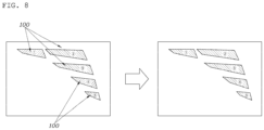
- FIG. 8 illustrates additional correction by the vehicle light 100 correction system according to an embodiment of the present disclosure.
- the vehicle light 100 correction system includes: a light source controller 200 configured to control the light source 60 of the vehicle light 100; a memory 300 configured to store target color coordinates which are color coordinates of light to be implemented through the vehicle light 100; a measurement unit 400 configured to measure, while being outside the vehicle light 100, color coordinates of light emitted through the vehicle light 100; and a correction controller 500 configured to control the vehicle light 100 so as to generate light with target color coordinates through the light source controller 200, measure color coordinates of the vehicle light 100 through the measurement unit 400, and cause the light source controller 200 to perform color coordinate correction control of the light source 60 as much as the difference between the target color coordinates and the measured color coordinates.
- a light source controller 200 configured to control the light source 60 of the vehicle light 100
- a memory 300 configured to store target color coordinates which are color coordinates of light to be implemented through the vehicle light 100
- a measurement unit 400 configured to measure, while being outside the vehicle light 100, color coordinates of light emitted through the vehicle light 100
- a correction controller 500 configured
- the light source 60 may be a color-changeable RGB LED, and the light source controller 200 may control the color of the RGB LED to change.
- FIG. 6 illustrates the first embodiment of the vehicle light 100 correction system according to an embodiment of the present disclosure.
- color coordinates of light from the light source 60 which is emitted after passing through a specimen formed with the same color as the outer paint layer 20, may be identified, and the measurement unit 400 may measure the color coordinates of the light (S10).
- Color coordinates of light from the light source 60, measured by the measurement unit 400 after passing through the specimen, may be stored in the memory 300.
- the memory 300 may store target color coordinates, which are color coordinates of light to be implemented through the vehicle light 100 (S11).
- the correction controller 500 may be connected to the memory 300 so as to calculate the amount of correction ( ⁇ Cx, ⁇ Cy) between the target color coordinates and the color coordinates of light that has passed through the specimen (S12), and may cause the light source controller 200 to perform color coordinate correction control of the light source 60 on the basis of the calculated amount of correction ( ⁇ Cx, ⁇ Cy) (S13).
- such control may turn on the light source 60, which then emits light.
- the light When passing through the light lens 1, the light may be emitted with the target color coordinates.
- the correction controller 500 may control the light controller 200 in connection with an actual product such that, when the light source 60 emits light, the measurement unit 400 measures the emitted light reaching the target color coordinates, and the correction controller 500 may confirm whether the measured color coordinates satisfy the target color coordinates (S14).
- parts 1 and 4 (right-diagonal shading) of the vehicle light 100 fail to satisfy the target color coordinates.
- An external factor such as the thickness of paint of the outer paint layer 20, causes such a problem in that light that has passed through the light lens 1 fails to satisfy the target color coordinates.
- additional correction of an additional light source 60 may proceed as follow:
- the correction controller 500 may derive the difference value between the target color coordinates and the measured color coordinates.
- the light source controller 200 may then cause the light source 60 to emit light, the color coordinates of which are changed as much as the color coordinates difference value, such that the color coordinates of light measured by the measurement unit 400 reach the target color coordinates.
- the measurement unit 400 may additionally measure color coordinates of light emitted by the vehicle light 100, which requires additional correction (S15).
- the correction controller 500 may calculate the amount of additional correction ( ⁇ Cx', ⁇ Cy') for correcting the measured color coordinates to the target color coordinates, and may control the light controller 200 on the basis of the amount of additional correction ( ⁇ Cx', ⁇ Cy') (S16).
- the amount of additional correction ( ⁇ Cx', ⁇ Cy') may be identified as illustrated in FIG. 2D .
- a diagnosis unit 600 for measuring the paint thickness of the outer paint film 20 may be further included.
- the correction controller 500 may calculates the amount of additional correction ( ⁇ Cx', ⁇ Cy') on the basis of the difference between the paint thickness detected by the diagnosis unit 600 and a reference thickness, and may cause the light source controller 200 to perform color coordinate correction control of the light source 60 so as to reflect the amount of additional correction ( ⁇ Cx', ⁇ Cy').
- the diagnosis unit 600 may measure the paint thickness of the outer paint layer 20 disposed on the vehicle light 100, which requires additional correction (S17).
- the correction controller 500 may calculate the amount of additional correction ( ⁇ Cx', ⁇ Cy') for correction to the target color coordinates on the basis of the measured paint thickness, and may control the light controller 200 on the basis of the amount of additional correction ( ⁇ Cx', ⁇ Cy') (S18).
- the correction controller 500 may control the light source controller 200 such that, if the paint thickness is larger than the preset value, further correction is made as much as the inclination of the existing amount of correction ( ⁇ Cx, ⁇ Cy) and, if the paint thickness is smaller than the preset value, less correction is made as much as the inclination of the existing amount of correction ( ⁇ Cx, ⁇ Cy) .
- Such control of the color of the light source 60 is advantageous in that color coordinates of light from the light source, which are changed after passing through the outer paint layer 20, are controlled to reach the target color coordinates, thereby observing regulations regarding the vehicle light color.
- the above system may be executed in an automated manner without operators' intervention.
Abstract
A vehicle light includes: a light lens having a base panel made of a transparent plastic material, an outer paint layer disposed on an outer surface of the base panel, and an inner paint layer disposed on an inner surface of the base panel and including a light-transmitting hole formed therein; and a light source installed to be spaced apart from the light lens, in which light from the light source is transmitted out of the light lens through the light-transmitting hole and the base panel.
Description
- The present disclosure relates to a vehicle light lens, a vehicle light, and a correction system thereof and, more particularly, to a technology regarding a vehicle light configured to form the same color as the body of the vehicle when turned off and to become a lamp when turned on.
- In general, vehicles have lighting devices for the purpose of illuminating objects in the traveling direction during nighttime driving, and lighting devices for the purpose of making the driving status of the vehicles recognized by other vehicles or road users. Headlights (also referred to as headlamps) are lighting devices for illuminating the front path in the vehicle traveling direction.
- Such lamps are classified into headlamps, fog lamps, turn signals, brake lamps, and reverse lamps, which emit light in different directions with regard to the road, respectively.
- Such vehicle lamps provide identification of objects by emitting light forwards from lightbulbs, and have recently lightguides applied thereto to improve the exterior design such that light is emitted with specific images.
- However, vehicle lamps are limited to conventional colors, and have design-related restrictions.
- The above descriptions regarding background technologies have been made only to help understanding of the background of the present disclosure, and are not to be deemed by those skilled in the art to correspond to already-known prior arts.
- The present disclosure has been proposed in order to solve the above-mentioned problems, and it is an aspect of the present disclosure to provide a vehicle light and a correction system thereof, such that when the vehicle light is not turned on, the same forms the same color with the body of the vehicle and, when turned on, the light can emit light to the outside with target color coordinates set by the designer.
- A vehicle light lens according to the present disclosure includes: a base panel made of a transparent material and having a panel shape so as to constitute a lens of a vehicle light; an outer paint layer disposed on an outer surface of the base panel with regard to the vehicle light; and an inner paint layer disposed on an inner surface of the base panel with regard to the vehicle light and including a light-transmitting hole formed therein such that light from a light source is transmitted outwards through the base panel.
- The vehicle light lens may further include a clear coating layer disposed on a surface of the outer paint layer.
- The outer paint layer may be a half paint layer having a color so as to transmit the light from the light source at a predetermined ratio.
- Light from the light source may be transmitted out of the vehicle light after a color coordinate change through the outer paint layer.
- The outer paint layer may have an identical color as a vehicle component panel adjacent to the vehicle light.
- The light-transmitting hole may be formed to penetrate the inner paint layer such that light from the light source directly reaches the base panel.
- The inner paint layer may be a black primer layer configured to prevent light from the light source from directly reaching the base panel, except for the light transmitting-hole.
- The base panel may have an identical material and an identical thickness as a base panel of a vehicle component panel adjacent to the vehicle light.
- The outer paint layer may have an identical color and an identical thickness as an outer paint layer of a vehicle component panel adjacent to the vehicle light.
- The outer paint layer may have an outer surface constitutes a common surface at an identical height with an outer surface of an outer paint layer of a vehicle component panel adjacent to the vehicle light.
- A vehicle light according to the present disclosure includes: a light lens including a base panel made of a transparent plastic material, an outer paint layer disposed on an outer surface of the base panel, and an inner paint layer disposed on an inner surface of the base panel and including a light-transmitting hole formed therein; and a light source installed to be spaced apart from the light lens, in which light from the light source is transmitted out of the light lens through the light-transmitting hole and the base panel.
- A vehicle light correction system according to the present disclosure includes: a light source controller configured to control the light source of the vehicle light; a memory configured to store target color coordinates which are color coordinates of light to be implemented through the vehicle light; a measurement unit disposed outside the vehicle light and configured to measure color coordinates of light emitted through the vehicle light; and a correction controller configured to control the vehicle light to generate light having target color coordinates through the light source controller, to measure color coordinates of the vehicle light through the measurement unit, and to cause the light source controller to perform color coordinate correction control of the light source as much as a difference value between the target color coordinates and the measured color coordinates.
- The correction controller may derive the difference value between the target color coordinates and the measured color coordinates, and the light source controller may cause the light source to emit light after changing color coordinates as much as the difference value such that color coordinates of light measured by the measurement unit reach the target color coordinates.
- The system may further include a diagnosis unit configured to measure a paint thickness of the outer paint layer, in which the correction controller calculates an amount of additional correction through a difference between the paint thickness measured by the diagnosis unit and a reference thickness, and causes the light source controller to perform color coordinate correction control of the light source so as to reflect the amount of additional correction.
- A vehicle light lens, a vehicle light, and a correction thereof, according to the present disclosure, are advantageous in that, when the vehicle light is not turned on, the outer paint layer of the light lens is formed with the same color as the body of the vehicle, and there is no level difference between the light lens and an outer panel of the vehicle such that the vehicle exterior looks as if the vehicle body and the vehicle light were integrated, thereby improving the exterior appearance of the vehicle and improving the product value of the vehicle.
- In addition, the color of the light source is controlled such that color coordinates of light from the light source, which are changed after passing through the outer paint layer, are controlled to reach target color coordinates, thereby observing regulations regarding the vehicle light color.
- In addition, the light source is made of an RGB LED such that, by controlling the color of light from the light source, color coordinates of light emitted to the outside can reach target color coordinates by using existing paint and equipment, without a separate additional component.
- The above and other aspects, features, and advantages of the present disclosure will be more apparent from the following detailed description taken in conjunction with the accompanying drawings, in which:
-
FIG. 1 is a sectional view of a vehicle light according to an embodiment of the present disclosure; -
FIGS. 2A, 2B, 2C and 2D illustrate color coordinate conversion of a light source; -
FIG. 3 illustrates a vehicle light according to an embodiment of the present disclosure; -
FIG. 4 is a side sectional view ofFIG. 3 ; -
FIG. 5 illustrates the configuration of a vehicle light correction system according to an embodiment of the present disclosure; -
FIG. 6 andFIG. 7 are flowcharts illustrating operation of a vehicle light correction system according to an embodiment of the present disclosure; and -
FIG. 8 illustrates additional correction by a vehicle light correction system according to an embodiment of the present disclosure. - Hereinafter, embodiments disclosed in the present specification will be described in detail with reference to the accompanying drawings, and the same or similar elements are given the same and similar reference numerals, so duplicate descriptions thereof will be omitted.
- The terms "module" and "unit" used for the elements in the following description are given or interchangeably used in consideration of only the ease of writing the specification, and do not have distinct meanings or roles by themselves.
- In describing the embodiments disclosed in the present specification, when the detailed description of the relevant known technology is determined to unnecessarily obscure the gist of the present disclosure, the detailed description may be omitted.
- Further, the accompanying drawings are provided only for easy understanding of the embodiments disclosed in the present specification, and the technical spirit disclosed herein is not limited to the accompanying drawings, and it should be understood that all changes, equivalents, or substitutes thereof are included in the spirit and scope of the present disclosure.
- Terms including an ordinal number such as "first", "second", or the like may be used to describe various elements, but the elements are not limited to the terms. The above terms are used only for the purpose of distinguishing one element from another element.
- In the case where an element is referred to as being "connected" or "coupled" to any other element, it should be understood that another element may be provided therebetween, as well as that the element may be directly connected or coupled to the other element. In contrast, in the case where an element is "directly connected" or "directly coupled" to any other element, it should be understood that no other element is present therebetween.
- A singular expression may include a plural expression unless they are definitely different in the context.
- As used herein, the expression "include" or "have" are intended to specify the existence of mentioned features, numbers, steps, operations, elements, components, or combinations thereof, and should be construed as not precluding the possible existence or addition of one or more other features, numbers, steps, operations, elements, components, or combinations thereof.
- A controller may include a communication device that communicates with other controllers or sensors in order to control functions in charge, a memory that stores an operating system or logic instructions, input/output information, and the like, and one or more processors that perform determinations, computations, decisions, and the like.
-
FIG. 1 is a sectional view of avehicle light 100 according to an embodiment of the present disclosure. - An exemplary embodiment of a
vehicle light lens 1 according to an embodiment of the present disclosure will now be described with reference toFIG. 1 . - The
vehicle light lens 1 may include multiple lenses as illustrated inFIG. 1 , and details of the multiple lenses will be described later. - A
vehicle light lens 1 according to an embodiment of the present disclosure includes: abase panel 10 made of a transparent material and configured in a panel shape so as to constitute the lens of thevehicle light 100; anouter paint layer 20 provided on the outer surface of thebase panel 10 with regard to thevehicle light 100; and aninner paint layer 30 provided on the inner surface of thebase panel 10 with regard to thevehicle light 100, a light-transmittinghole 31 being formed in theinner paint layer 30 such that light from alight source 60 is transmitted to the outside through thebase panel 10. - The
base panel 10 may be formed to extend from a bumper portion and made of a transparent plastic material having an excellent optical transmittance. Accordingly, thebase panel 10 may protect thelight source 60 disposed in thevehicle light 100 while transmitting light. - The
outer paint layer 20 may be disposed on the outside of thebase panel 10 such that, when thelight source 60 disposed in thevehicle light 100 is turned on, light is transmitted to the outside through the base panel and theouter paint layer 20. - The
outer paint layer 20 may be a half-paint layer having a color so as to transmit light from thelight source 60 at a predetermined ratio. -
FIG. 2 illustrates color coordinate conversion of thelight source 60. - As illustrated in
FIG. 2A , when thelight source 60 emits light, the light may pass through thetransparent base panel 10 and then pass through theouter paint layer 20 which is a half paint layer having a color (e.g., a paint layer with half-transparency or semitransparency), such that the light passing through thebase panel 10 and theouter paint layer 20 can have the color of the half paint layer. - In addition, the color of the
outer paint layer 20 may be identical to the color of anouter paint layer 20 of a vehicle component panel adjacent to thevehicle light 100 of the vehicle, and the thickness may be identical. - As illustrated in
FIG. 1 , theouter paint layer 20 may have the same color as that of a vehicle component panel adjacent to thevehicle light 100 of the vehicle when thelight source 60 is not turned on such that thevehicle light 100 becomes a part of the exterior of the vehicle. Such a vehicle design element may improve the aesthetic appearance of the vehicle and may emit light (main role of light 100) when thelight source 60 is turned on. - The
base panel 10 may have the same material and thickness as those of abase panel 10 of a vehicle component panel adjacent to thevehicle light 100. The outer surface of theouter paint layer 20 may constitute a common surface at the same height with the outer surface of anouter paint layer 20 of the vehicle component panel adjacent to thevehicle light 100. - As illustrated in
FIG. 1 , the base panel may be formed to extend with the same material and the same thickness as those of a vehicle component panel adjacent to thevehicle light 100, and theouter paint layer 20 may extend with same material and the same thickness as those of the vehicle component panel adjacent to thevehicle light 100, thereby being integrated with the vehicle component panel adjacent to thevehicle light 100 when thelight source 60 is not turned on. When thelight source 60 is turned on, only thevehicle light 100 part may emit light such that thevehicle light 100 is recognized. - As illustrated in
FIG. 1 , theinner paint layer 30 is provided on the inner surface of thebase panel 10 with regard to thevehicle light 100, a light-transmittinghole 31 being formed in theinner paint layer 30 such that light from thelight source 60 is transmitted to the outside through thebase panel 10. Accordingly, light emitted by thelight source 60 may be transmitted only through the portion in which the light-transmittinghole 31 is positioned. In addition, multiple light-transmittingholes 31 may be formed and disposed in positions desired by the designer. - The
inner paint layer 30 may be a black primer layer such that, except for the light-transmittingholes 31, light from thelight source 60 does not directly reach thebase panel 10. - As a result, light emitted by the
light source 60 is transmitted only through the light-transmittingholes 31, and parts other than the light-transmittingholes 31 prevent light from thelight source 60 from being emitted to the outside. Therefore, the designer may configure the light-transmittingholes 31 in a desired shape such that light emitted by thelight source 60 is emitted to the outside after being transmitted in the shape of the light-transmittingholes 31. - The
inner paint layer 30 may be a black primer layer such that light does not pass therethrough. Light from thelight source 60 may pass through the light-transmittingholes 31 formed through theinner paint layer 30 and may directly reach thebase panel 10. After reaching thebase panel 10, the light may successively pass through thebase panel 10 and theouter paint layer 20, thereby being emitted to the outside of the vehicle. - A
clear coating layer 40 may be additionally disposed on the surface of theouter paint layer 20. - The
clear coating layer 40 may be a thin layer applied to the outer surface of theouter paint layer 20 to protect the outer surface thereof such that light, the color of which is changed after passing through theouter paint layer 20, can be transmitted to the outside with no change. - The
clear coating layer 40 may be continuously applied to thevehicle light 100 and to a vehicle component adjacent to thevehicle light 100 as illustrated inFIG. 1 so as to improve the integrity between thevehicle light 100 and to the vehicle component adjacent to thevehicle light 100. - Accordingly, when the
vehicle light 100 is not turned on, thevehicle light 100 and to the vehicle component adjacent to thevehicle light 100 appear integrated, and when thevehicle light 100 is turned on, only thevehicle light 100 may emit light. -
FIG. 3 illustrates avehicle light 100 according to an embodiment of the present disclosure.FIG. 4 is a side sectional view ofFIG. 3 . - An exemplary embodiment of a
vehicle light 100 according to an embodiment of the present disclosure will now be described with reference toFIG. 1 to FIG. 4 . - A
vehicle light 100 according to the present disclosure may include: alight lens 1 including abase panel 10 made of a transparent material, anouter paint layer 20 provided on the outer surface of thebase panel 10, and aninner paint layer 30 provided on the inner surface of thebase panel 10, a light-transmittinghole 31 being formed in theinner paint layer 30; and alight source 60 installed to be spaced apart from thelight lens 1. Light from thelight source 60 may be transmitted to the outside of thelight lens 1 through the light-transmittinghole 31 and thebase panel 10. - As illustrated in
FIG. 1 , thevehicle light 100 includes avehicle light lens 1 according to the present disclosure and alight source 60 disposed to be spaced apart from the inside of thelight lens 1, and may further include abarrier 50 extending from the inside of the lens toward thelight source 60 so as to distinguish between thevehicle light 100 and an adjacent vehicle component panel inside the vehicle. - The
barrier 50 may be configured such that light from thelight source 60 is emitted only toward the lens inside thevehicle light 100, thereby increasing the efficiency of light. - Light emitted from the
light source 60 may undergo a color coordinate change while passing through theouter paint layer 20 formed as a half paint layer, and may then be transmitted to the outside of thevehicle light 100. - As illustrated in
FIG. 2B , when light is emitted by thelight source 60 and passes through thebase panel 10 and theouter paint layer 20, the light emitted from the existinglight source 60 may undergo a color coordinate change and may then be transmitted to the outside. - The
light source 60 may be a color-changeable RGB LED such that various colors of light can be emitted. Light from thelight source 60 may be emitted after a color coordinate change such that the same is exposed to the outside with target color coordinates set by the designer. - As illustrated in
FIG. 3 , when thelight source 60 is not turned on, thevehicle light 100 lens and the vehicle body panel may maintain the same color, and when turned on, light may be emitted with the target color. - As illustrated in
FIG. 4 , in an embodiment of thevehicle light 100, anadditional light 100 for reflecting light from thelight source 60 may be inserted. - A
vehicle light 100 correction system for changing color coordinates of light from thelight source 60 described above will now be described. -
FIG. 5 illustrates the configuration of avehicle light 100 correction system according to an embodiment of the present disclosure.FIG. 6 andFIG. 7 are flowcharts illustrating operations of thevehicle light 100 correction system according to an embodiment of the present disclosure.FIG. 8 illustrates additional correction by thevehicle light 100 correction system according to an embodiment of the present disclosure. - An exemplary embodiment of the
vehicle light 100 correction system according to the present disclosure will now be described with reference toFIG. 2 to FIG. 8 . - As illustrated in
FIG. 5 , thevehicle light 100 correction system according to the present disclosure includes: alight source controller 200 configured to control thelight source 60 of thevehicle light 100; amemory 300 configured to store target color coordinates which are color coordinates of light to be implemented through thevehicle light 100; ameasurement unit 400 configured to measure, while being outside thevehicle light 100, color coordinates of light emitted through thevehicle light 100; and acorrection controller 500 configured to control thevehicle light 100 so as to generate light with target color coordinates through thelight source controller 200, measure color coordinates of thevehicle light 100 through themeasurement unit 400, and cause thelight source controller 200 to perform color coordinate correction control of thelight source 60 as much as the difference between the target color coordinates and the measured color coordinates. - The
light source 60 may be a color-changeable RGB LED, and thelight source controller 200 may control the color of the RGB LED to change. -
FIG. 6 illustrates the first embodiment of thevehicle light 100 correction system according to an embodiment of the present disclosure. - As illustrated in
FIG. 2C , color coordinates of light from thelight source 60, which is emitted after passing through a specimen formed with the same color as theouter paint layer 20, may be identified, and themeasurement unit 400 may measure the color coordinates of the light (S10). - Color coordinates of light from the
light source 60, measured by themeasurement unit 400 after passing through the specimen, may be stored in thememory 300. Thememory 300 may store target color coordinates, which are color coordinates of light to be implemented through the vehicle light 100 (S11). - The
correction controller 500 may be connected to thememory 300 so as to calculate the amount of correction (±ΔCx, ΔCy) between the target color coordinates and the color coordinates of light that has passed through the specimen (S12), and may cause thelight source controller 200 to perform color coordinate correction control of thelight source 60 on the basis of the calculated amount of correction (±ΔCx, ΔCy) (S13). - As illustrated in
FIG. 3 , such control may turn on thelight source 60, which then emits light. When passing through thelight lens 1, the light may be emitted with the target color coordinates. - The
correction controller 500 may control thelight controller 200 in connection with an actual product such that, when thelight source 60 emits light, themeasurement unit 400 measures the emitted light reaching the target color coordinates, and thecorrection controller 500 may confirm whether the measured color coordinates satisfy the target color coordinates (S14). - As illustrated on the left in
FIG. 8 , it may be confirmed thatparts ① and ④ (right-diagonal shading) of thevehicle light 100 fail to satisfy the target color coordinates. - An external factor, such as the thickness of paint of the
outer paint layer 20, causes such a problem in that light that has passed through thelight lens 1 fails to satisfy the target color coordinates. - In order to solve such a problem, additional correction of an additional
light source 60 may proceed as follow:
In the first embodiment of additional correction of thelight source 60, referring toFIG. 6 , thecorrection controller 500 may derive the difference value between the target color coordinates and the measured color coordinates. Thelight source controller 200 may then cause thelight source 60 to emit light, the color coordinates of which are changed as much as the color coordinates difference value, such that the color coordinates of light measured by themeasurement unit 400 reach the target color coordinates. - The
measurement unit 400 may additionally measure color coordinates of light emitted by thevehicle light 100, which requires additional correction (S15). Thecorrection controller 500 may calculate the amount of additional correction (±ΔCx', ΔCy') for correcting the measured color coordinates to the target color coordinates, and may control thelight controller 200 on the basis of the amount of additional correction (±ΔCx', ΔCy') (S16). - The amount of additional correction (±ΔCx', ΔCy') may be identified as illustrated in
FIG. 2D . - In the second embodiment of additional correction of the
light source 60, referring toFIG. 7 , adiagnosis unit 600 for measuring the paint thickness of theouter paint film 20 may be further included. Thecorrection controller 500 may calculates the amount of additional correction (±ΔCx', ΔCy') on the basis of the difference between the paint thickness detected by thediagnosis unit 600 and a reference thickness, and may cause thelight source controller 200 to perform color coordinate correction control of thelight source 60 so as to reflect the amount of additional correction (±ΔCx', ΔCy'). - The
diagnosis unit 600 may measure the paint thickness of theouter paint layer 20 disposed on thevehicle light 100, which requires additional correction (S17). Thecorrection controller 500 may calculate the amount of additional correction (±ΔCx', ΔCy') for correction to the target color coordinates on the basis of the measured paint thickness, and may control thelight controller 200 on the basis of the amount of additional correction (±ΔCx', ΔCy') (S18). - The
correction controller 500 may control thelight source controller 200 such that, if the paint thickness is larger than the preset value, further correction is made as much as the inclination of the existing amount of correction (±ΔCx, ΔCy) and, if the paint thickness is smaller than the preset value, less correction is made as much as the inclination of the existing amount of correction (±ΔCx, ΔCy) . - Such control of the color of the
light source 60 is advantageous in that color coordinates of light from the light source, which are changed after passing through theouter paint layer 20, are controlled to reach the target color coordinates, thereby observing regulations regarding the vehicle light color. - The above system may be executed in an automated manner without operators' intervention.
- Although the present disclosure has been described and illustrated in conjunction with particular embodiments thereof, it will be apparent to those skilled in the art that various improvements and modifications may be made to the present disclosure without departing from the technical idea of the present disclosure defined by the appended claims.
Claims (15)
- A vehicle light lens comprising:a base panel made of a transparent material and having a panel shape so as to constitute a lens of a vehicle light;an outer paint layer disposed on an outer surface of the base panel with regard to the vehicle light; andan inner paint layer disposed on an inner surface of the base panel with regard to the vehicle light and including a light-transmitting hole formed therein such that light from a light source is transmitted outwards through the base panel.
- The vehicle light lens of claim 1, further comprising a clear coating layer disposed on a surface of the outer paint layer.
- The vehicle light lens of claim 1, wherein the outer paint layer is a half paint layer having a color so as to transmit the light from the light source at a predetermined ratio.
- The vehicle light lens of claim 3, wherein the outer paint layer has an identical color as a vehicle component panel adjacent to the vehicle light.
- The vehicle light lens of claim 3, wherein the outer paint layer is formed with an identical color as a vehicle component panel adjacent to the vehicle light such that the light becomes a part of a vehicle exterior when the light source is not turned on and the vehicle light emits light having target color coordinates when the light source is turned on.
- The vehicle light lens of claim 1, wherein the light-transmitting hole is formed to penetrate the inner paint layer such that the light from the light source directly reaches the base panel.
- The vehicle light lens of claim 1, wherein the inner paint layer is a black primer layer configured to prevent the light from the light source from directly reaching the base panel, except for the light transmitting-hole.
- The vehicle light lens of claim 1, wherein the base panel has an identical material and an identical thickness as a base panel of a vehicle component panel adjacent to the vehicle light.
- The vehicle light lens of claim 1, wherein the outer paint layer has an identical color and an identical thickness as an outer paint layer of a vehicle component panel adjacent to the vehicle light.
- The vehicle light lens of claim 1, wherein the outer paint layer has an outer surface constitutes a common surface at an identical height with an outer surface of an outer paint layer of a vehicle component panel adjacent to the vehicle light.
- A vehicle light comprising:a light lens comprising a base panel made of a transparent plastic material, an outer paint layer disposed on an outer surface of the base panel, and an inner paint layer disposed on an inner surface of the base panel and having a light-transmitting hole formed therein; anda light source installed to be spaced apart from the light lens,wherein light from the light source is transmitted out of the light lens through the light-transmitting hole and the base panel.
- The vehicle light of claim 11, wherein the light from the light source is transmitted out of the vehicle light after a color coordinate change through the outer paint layer.
- A system for correcting a vehicle light comprising a light lens including a base panel made of a transparent plastic material, an outer paint layer disposed on an outer surface of the base panel, and an inner paint layer disposed on an inner surface of the base panel and having a light-transmitting hole formed therein; and a light source installed to be spaced apart from the light lens, the system comprising:a light source controller configured to control the light source of the vehicle light;a memory configured to store target color coordinates which are color coordinates of light to be implemented through the vehicle light;a measurement unit disposed outside the vehicle light and configured to measure color coordinates of light emitted through the vehicle light; anda correction controller configured to control the vehicle light to generate light having the target color coordinates through the light source controller, to measure color coordinates of the vehicle light through the measurement unit, and to cause the light source controller to perform color coordinate correction control of the light source as much as a difference value between the target color coordinates and the measured color coordinates of the vehicle light.
- The system of claim 13, wherein the correction controller derives the difference value between the target color coordinates and the measured color coordinates, and
the light source controller causes the light source to emit light after changing color coordinates as much as the difference value such that color coordinates of light measured by the measurement unit reach the target color coordinates. - The system of claim 13, further comprising a diagnosis unit configured to measure a paint thickness of the outer paint layer,
wherein the correction controller calculates an amount of additional correction through a difference between the paint thickness measured by the diagnosis unit and a reference thickness, and causes the light source controller to perform the color coordinate correction control of the light source so as to reflect the amount of additional correction.
Applications Claiming Priority (1)
| Application Number | Priority Date | Filing Date | Title |
|---|---|---|---|
| KR1020220132526A KR20240052457A (en) | 2022-10-14 | 2022-10-14 | Light lens of vehicle, light of vehicle, and its correction system |
Publications (1)
| Publication Number | Publication Date |
|---|---|
| EP4354018A1 true EP4354018A1 (en) | 2024-04-17 |
Family
ID=87553556
Family Applications (1)
| Application Number | Title | Priority Date | Filing Date |
|---|---|---|---|
| EP23188887.6A Pending EP4354018A1 (en) | 2022-10-14 | 2023-08-01 | Vehicle light lens, vehicle light, and correction system thereof |
Country Status (5)
| Country | Link |
|---|---|
| US (1) | US20240125442A1 (en) |
| EP (1) | EP4354018A1 (en) |
| JP (1) | JP2024058574A (en) |
| KR (1) | KR20240052457A (en) |
| CN (1) | CN117889392A (en) |
Citations (10)
| Publication number | Priority date | Publication date | Assignee | Title |
|---|---|---|---|---|
| FR2886375A1 (en) * | 2005-05-27 | 2006-12-01 | Valeo Vision Sa | Motor vehicle indicator lamp has variable colour provided by two transparent coloured filters that interact to give a predetermined light colour |
| US8113695B2 (en) * | 2005-02-04 | 2012-02-14 | Adac Plastics, Inc. | Trim component with concealed indicium |
| US20150291085A1 (en) * | 2014-04-10 | 2015-10-15 | Kerry Manning | Illuminated translucent body panels and methods therefor |
| DE102018211457A1 (en) * | 2018-07-11 | 2020-01-16 | Bayerische Motoren Werke Aktiengesellschaft | Process for manufacturing an exterior component and exterior component |
| EP3623227A1 (en) * | 2018-09-14 | 2020-03-18 | Compagnie Plastic Omnium | High-contrast backlit vehicle body part |
| WO2020126944A1 (en) * | 2018-12-17 | 2020-06-25 | Compagnie Plastic Omnium | Backlit bodywork part |
| EP3815838A1 (en) * | 2019-11-04 | 2021-05-05 | Compagnie Plastic Omnium SE | Method for producing a transparent part for a vehicle |
| US11204146B2 (en) * | 2019-12-23 | 2021-12-21 | Flex-N-Gate France | Lighting device for vehicle having a translucent element with a mask applied to interior surface thereof |
| US11384915B1 (en) * | 2021-03-12 | 2022-07-12 | Hyundai Motor Company | Garnishless type hidden lamp for vehicle |
| DE102022000054A1 (en) * | 2021-01-08 | 2022-07-14 | Hyundai Mobis Co., Ltd. | Lighting device for a vehicle and method for its manufacture |
Family Cites Families (1)
| Publication number | Priority date | Publication date | Assignee | Title |
|---|---|---|---|---|
| KR102399480B1 (en) | 2020-05-08 | 2022-05-17 | 현대자동차주식회사 | Hidden light apparatus |
-
2022
- 2022-10-14 KR KR1020220132526A patent/KR20240052457A/en unknown
-
2023
- 2023-07-25 US US18/225,869 patent/US20240125442A1/en active Pending
- 2023-07-28 JP JP2023123188A patent/JP2024058574A/en active Pending
- 2023-08-01 EP EP23188887.6A patent/EP4354018A1/en active Pending
- 2023-09-14 CN CN202311192743.9A patent/CN117889392A/en active Pending
Patent Citations (10)
| Publication number | Priority date | Publication date | Assignee | Title |
|---|---|---|---|---|
| US8113695B2 (en) * | 2005-02-04 | 2012-02-14 | Adac Plastics, Inc. | Trim component with concealed indicium |
| FR2886375A1 (en) * | 2005-05-27 | 2006-12-01 | Valeo Vision Sa | Motor vehicle indicator lamp has variable colour provided by two transparent coloured filters that interact to give a predetermined light colour |
| US20150291085A1 (en) * | 2014-04-10 | 2015-10-15 | Kerry Manning | Illuminated translucent body panels and methods therefor |
| DE102018211457A1 (en) * | 2018-07-11 | 2020-01-16 | Bayerische Motoren Werke Aktiengesellschaft | Process for manufacturing an exterior component and exterior component |
| EP3623227A1 (en) * | 2018-09-14 | 2020-03-18 | Compagnie Plastic Omnium | High-contrast backlit vehicle body part |
| WO2020126944A1 (en) * | 2018-12-17 | 2020-06-25 | Compagnie Plastic Omnium | Backlit bodywork part |
| EP3815838A1 (en) * | 2019-11-04 | 2021-05-05 | Compagnie Plastic Omnium SE | Method for producing a transparent part for a vehicle |
| US11204146B2 (en) * | 2019-12-23 | 2021-12-21 | Flex-N-Gate France | Lighting device for vehicle having a translucent element with a mask applied to interior surface thereof |
| DE102022000054A1 (en) * | 2021-01-08 | 2022-07-14 | Hyundai Mobis Co., Ltd. | Lighting device for a vehicle and method for its manufacture |
| US11384915B1 (en) * | 2021-03-12 | 2022-07-12 | Hyundai Motor Company | Garnishless type hidden lamp for vehicle |
Also Published As
| Publication number | Publication date |
|---|---|
| JP2024058574A (en) | 2024-04-25 |
| KR20240052457A (en) | 2024-04-23 |
| CN117889392A (en) | 2024-04-16 |
| US20240125442A1 (en) | 2024-04-18 |
Similar Documents
| Publication | Publication Date | Title |
|---|---|---|
| US9791123B2 (en) | Vehicle signal lamp | |
| JP2012028155A (en) | Lamp unit for vehicle | |
| CN104943547A (en) | Vehicle instrument panel equipped with an LED backlighting device for lighting a graphic area | |
| US10514143B2 (en) | Light module comprising a primary optical element equipped with two forming layers | |
| US11780365B2 (en) | Optical device and direction display device | |
| CN104890564A (en) | Vehicle head lamp | |
| US10697608B2 (en) | Lamp for vehicle | |
| CN101055065B (en) | Vehicle lighting device | |
| US11060688B1 (en) | Hidden light apparatus for vehicle having a grille with grid and perforated grid panel | |
| EP4354018A1 (en) | Vehicle light lens, vehicle light, and correction system thereof | |
| CN110873315B (en) | Lighting device for vehicle | |
| KR20130081274A (en) | Color light guide applying lamp for vehicle | |
| US11059416B1 (en) | Electrochromic adaptive driving beam system and method | |
| CN211040839U (en) | Independent automobile license plate lamp | |
| JP4138203B2 (en) | Vehicle lighting | |
| US20040217856A1 (en) | Automotive lamp | |
| CN217816582U (en) | Multi-LED uniform light-emitting mirror structure | |
| JP2014175231A (en) | Lighting for vehicle | |
| KR101776814B1 (en) | Automotive lamp | |
| US20240077184A1 (en) | Infrared lamp device and infrared lamp system for a vehicle | |
| CN210801012U (en) | Car lamp for realizing double lighting effects of thick wall and inner lens surface patterns by single light source | |
| US20240052989A1 (en) | Illumination module with multi light sources and headlight having the same | |
| JPS6315685B2 (en) | ||
| KR20210075516A (en) | Lamp assembly for vehicle | |
| CN108692251B (en) | Transmission type laser LED composite far and near light and auxiliary far light module |
Legal Events
| Date | Code | Title | Description |
|---|---|---|---|
| PUAI | Public reference made under article 153(3) epc to a published international application that has entered the european phase |
Free format text: ORIGINAL CODE: 0009012 |
|
| STAA | Information on the status of an ep patent application or granted ep patent |
Free format text: STATUS: THE APPLICATION HAS BEEN PUBLISHED |
|
| AK | Designated contracting states |
Kind code of ref document: A1 Designated state(s): AL AT BE BG CH CY CZ DE DK EE ES FI FR GB GR HR HU IE IS IT LI LT LU LV MC ME MK MT NL NO PL PT RO RS SE SI SK SM TR |