EP4353971A1 - Fluid and power provision apparatus - Google Patents
Fluid and power provision apparatus Download PDFInfo
- Publication number
- EP4353971A1 EP4353971A1 EP23202842.3A EP23202842A EP4353971A1 EP 4353971 A1 EP4353971 A1 EP 4353971A1 EP 23202842 A EP23202842 A EP 23202842A EP 4353971 A1 EP4353971 A1 EP 4353971A1
- Authority
- EP
- European Patent Office
- Prior art keywords
- piston
- collar
- assembly
- flowpath
- plenum
- Prior art date
- Legal status (The legal status is an assumption and is not a legal conclusion. Google has not performed a legal analysis and makes no representation as to the accuracy of the status listed.)
- Granted
Links
Images




Classifications
-
- F—MECHANICAL ENGINEERING; LIGHTING; HEATING; WEAPONS; BLASTING
- F04—POSITIVE - DISPLACEMENT MACHINES FOR LIQUIDS; PUMPS FOR LIQUIDS OR ELASTIC FLUIDS
- F04B—POSITIVE-DISPLACEMENT MACHINES FOR LIQUIDS; PUMPS
- F04B35/00—Piston pumps specially adapted for elastic fluids and characterised by the driving means to their working members, or by combination with, or adaptation to, specific driving engines or motors, not otherwise provided for
- F04B35/04—Piston pumps specially adapted for elastic fluids and characterised by the driving means to their working members, or by combination with, or adaptation to, specific driving engines or motors, not otherwise provided for the means being electric
-
- F—MECHANICAL ENGINEERING; LIGHTING; HEATING; WEAPONS; BLASTING
- F04—POSITIVE - DISPLACEMENT MACHINES FOR LIQUIDS; PUMPS FOR LIQUIDS OR ELASTIC FLUIDS
- F04B—POSITIVE-DISPLACEMENT MACHINES FOR LIQUIDS; PUMPS
- F04B35/00—Piston pumps specially adapted for elastic fluids and characterised by the driving means to their working members, or by combination with, or adaptation to, specific driving engines or motors, not otherwise provided for
- F04B35/06—Mobile combinations
-
- H—ELECTRICITY
- H02—GENERATION; CONVERSION OR DISTRIBUTION OF ELECTRIC POWER
- H02J—ELECTRIC POWER NETWORKS; CIRCUIT ARRANGEMENTS OR SYSTEMS FOR SUPPLYING OR DISTRIBUTING ELECTRIC POWER; SYSTEMS FOR STORING ELECTRIC ENERGY
- H02J7/00—Circuit arrangements for charging or discharging batteries or for supplying loads from batteries
- H02J7/34—Parallel operation in networks using both storage and other DC sources, e.g. providing buffering
- H02J7/345—Parallel operation in networks using both storage and other DC sources, e.g. providing buffering using capacitors as storage or buffering devices
-
- B—PERFORMING OPERATIONS; TRANSPORTING
- B60—VEHICLES IN GENERAL
- B60C—VEHICLE TYRES; TYRE INFLATION; TYRE CHANGING; CONNECTING VALVES TO INFLATABLE ELASTIC BODIES IN GENERAL; DEVICES OR ARRANGEMENTS RELATED TO TYRES
- B60C23/00—Devices for measuring, signalling, controlling, or distributing tyre pressure or temperature, specially adapted for mounting on vehicles; Arrangement of tyre inflating devices on vehicles, e.g. of pumps or of tanks; Tyre cooling arrangements
- B60C23/10—Arrangement of tyre-inflating pumps mounted on vehicles
-
- B—PERFORMING OPERATIONS; TRANSPORTING
- B60—VEHICLES IN GENERAL
- B60L—PROPULSION OF ELECTRICALLY-PROPELLED VEHICLES; SUPPLYING ELECTRIC POWER FOR AUXILIARY EQUIPMENT OF ELECTRICALLY-PROPELLED VEHICLES; ELECTRODYNAMIC BRAKE SYSTEMS FOR VEHICLES IN GENERAL; MAGNETIC SUSPENSION OR LEVITATION FOR VEHICLES; MONITORING OPERATING VARIABLES OF ELECTRICALLY-PROPELLED VEHICLES; ELECTRIC SAFETY DEVICES FOR ELECTRICALLY-PROPELLED VEHICLES
- B60L53/00—Methods of charging batteries, specially adapted for electric vehicles; Charging stations or on-board charging equipment therefor; Exchange of energy storage elements in electric vehicles
- B60L53/20—Methods of charging batteries, specially adapted for electric vehicles; Charging stations or on-board charging equipment therefor; Exchange of energy storage elements in electric vehicles characterised by converters located in the vehicle
-
- B—PERFORMING OPERATIONS; TRANSPORTING
- B60—VEHICLES IN GENERAL
- B60L—PROPULSION OF ELECTRICALLY-PROPELLED VEHICLES; SUPPLYING ELECTRIC POWER FOR AUXILIARY EQUIPMENT OF ELECTRICALLY-PROPELLED VEHICLES; ELECTRODYNAMIC BRAKE SYSTEMS FOR VEHICLES IN GENERAL; MAGNETIC SUSPENSION OR LEVITATION FOR VEHICLES; MONITORING OPERATING VARIABLES OF ELECTRICALLY-PROPELLED VEHICLES; ELECTRIC SAFETY DEVICES FOR ELECTRICALLY-PROPELLED VEHICLES
- B60L53/00—Methods of charging batteries, specially adapted for electric vehicles; Charging stations or on-board charging equipment therefor; Exchange of energy storage elements in electric vehicles
- B60L53/30—Constructional details of charging stations
-
- F—MECHANICAL ENGINEERING; LIGHTING; HEATING; WEAPONS; BLASTING
- F02—COMBUSTION ENGINES; HOT-GAS OR COMBUSTION-PRODUCT ENGINE PLANTS
- F02N—STARTING OF COMBUSTION ENGINES; STARTING AIDS FOR SUCH ENGINES, NOT OTHERWISE PROVIDED FOR
- F02N11/00—Starting of engines by means of electric motors
- F02N11/12—Starting of engines by means of mobile, e.g. portable, starting sets
-
- F—MECHANICAL ENGINEERING; LIGHTING; HEATING; WEAPONS; BLASTING
- F02—COMBUSTION ENGINES; HOT-GAS OR COMBUSTION-PRODUCT ENGINE PLANTS
- F02N—STARTING OF COMBUSTION ENGINES; STARTING AIDS FOR SUCH ENGINES, NOT OTHERWISE PROVIDED FOR
- F02N11/00—Starting of engines by means of electric motors
- F02N11/14—Starting of engines by means of electric starters with external current supply
-
- F—MECHANICAL ENGINEERING; LIGHTING; HEATING; WEAPONS; BLASTING
- F04—POSITIVE - DISPLACEMENT MACHINES FOR LIQUIDS; PUMPS FOR LIQUIDS OR ELASTIC FLUIDS
- F04B—POSITIVE-DISPLACEMENT MACHINES FOR LIQUIDS; PUMPS
- F04B17/00—Pumps characterised by combination with, or adaptation to, specific driving engines or motors
- F04B17/03—Pumps characterised by combination with, or adaptation to, specific driving engines or motors driven by electric motors
-
- F—MECHANICAL ENGINEERING; LIGHTING; HEATING; WEAPONS; BLASTING
- F04—POSITIVE - DISPLACEMENT MACHINES FOR LIQUIDS; PUMPS FOR LIQUIDS OR ELASTIC FLUIDS
- F04B—POSITIVE-DISPLACEMENT MACHINES FOR LIQUIDS; PUMPS
- F04B39/00—Component parts, details, or accessories, of pumps or pumping systems specially adapted for elastic fluids, not otherwise provided for in, or of interest apart from, groups F04B25/00 - F04B37/00
-
- F—MECHANICAL ENGINEERING; LIGHTING; HEATING; WEAPONS; BLASTING
- F04—POSITIVE - DISPLACEMENT MACHINES FOR LIQUIDS; PUMPS FOR LIQUIDS OR ELASTIC FLUIDS
- F04B—POSITIVE-DISPLACEMENT MACHINES FOR LIQUIDS; PUMPS
- F04B39/00—Component parts, details, or accessories, of pumps or pumping systems specially adapted for elastic fluids, not otherwise provided for in, or of interest apart from, groups F04B25/00 - F04B37/00
- F04B39/0005—Component parts, details, or accessories, of pumps or pumping systems specially adapted for elastic fluids, not otherwise provided for in, or of interest apart from, groups F04B25/00 - F04B37/00 adaptations of pistons
-
- F—MECHANICAL ENGINEERING; LIGHTING; HEATING; WEAPONS; BLASTING
- F04—POSITIVE - DISPLACEMENT MACHINES FOR LIQUIDS; PUMPS FOR LIQUIDS OR ELASTIC FLUIDS
- F04B—POSITIVE-DISPLACEMENT MACHINES FOR LIQUIDS; PUMPS
- F04B39/00—Component parts, details, or accessories, of pumps or pumping systems specially adapted for elastic fluids, not otherwise provided for in, or of interest apart from, groups F04B25/00 - F04B37/00
- F04B39/0005—Component parts, details, or accessories, of pumps or pumping systems specially adapted for elastic fluids, not otherwise provided for in, or of interest apart from, groups F04B25/00 - F04B37/00 adaptations of pistons
- F04B39/0022—Component parts, details, or accessories, of pumps or pumping systems specially adapted for elastic fluids, not otherwise provided for in, or of interest apart from, groups F04B25/00 - F04B37/00 adaptations of pistons piston rods
-
- F—MECHANICAL ENGINEERING; LIGHTING; HEATING; WEAPONS; BLASTING
- F04—POSITIVE - DISPLACEMENT MACHINES FOR LIQUIDS; PUMPS FOR LIQUIDS OR ELASTIC FLUIDS
- F04B—POSITIVE-DISPLACEMENT MACHINES FOR LIQUIDS; PUMPS
- F04B39/00—Component parts, details, or accessories, of pumps or pumping systems specially adapted for elastic fluids, not otherwise provided for in, or of interest apart from, groups F04B25/00 - F04B37/00
- F04B39/12—Casings; Cylinders; Cylinder heads; Fluid connections
- F04B39/121—Casings
-
- F—MECHANICAL ENGINEERING; LIGHTING; HEATING; WEAPONS; BLASTING
- F04—POSITIVE - DISPLACEMENT MACHINES FOR LIQUIDS; PUMPS FOR LIQUIDS OR ELASTIC FLUIDS
- F04B—POSITIVE-DISPLACEMENT MACHINES FOR LIQUIDS; PUMPS
- F04B39/00—Component parts, details, or accessories, of pumps or pumping systems specially adapted for elastic fluids, not otherwise provided for in, or of interest apart from, groups F04B25/00 - F04B37/00
- F04B39/12—Casings; Cylinders; Cylinder heads; Fluid connections
- F04B39/123—Fluid connections
-
- F—MECHANICAL ENGINEERING; LIGHTING; HEATING; WEAPONS; BLASTING
- F04—POSITIVE - DISPLACEMENT MACHINES FOR LIQUIDS; PUMPS FOR LIQUIDS OR ELASTIC FLUIDS
- F04B—POSITIVE-DISPLACEMENT MACHINES FOR LIQUIDS; PUMPS
- F04B39/00—Component parts, details, or accessories, of pumps or pumping systems specially adapted for elastic fluids, not otherwise provided for in, or of interest apart from, groups F04B25/00 - F04B37/00
- F04B39/12—Casings; Cylinders; Cylinder heads; Fluid connections
- F04B39/125—Cylinder heads
-
- F—MECHANICAL ENGINEERING; LIGHTING; HEATING; WEAPONS; BLASTING
- F04—POSITIVE - DISPLACEMENT MACHINES FOR LIQUIDS; PUMPS FOR LIQUIDS OR ELASTIC FLUIDS
- F04B—POSITIVE-DISPLACEMENT MACHINES FOR LIQUIDS; PUMPS
- F04B39/00—Component parts, details, or accessories, of pumps or pumping systems specially adapted for elastic fluids, not otherwise provided for in, or of interest apart from, groups F04B25/00 - F04B37/00
- F04B39/14—Provisions for readily assembling or disassembling
-
- H—ELECTRICITY
- H01—ELECTRIC ELEMENTS
- H01M—PROCESSES OR MEANS, e.g. BATTERIES, FOR THE DIRECT CONVERSION OF CHEMICAL ENERGY INTO ELECTRICAL ENERGY
- H01M10/00—Secondary cells; Manufacture thereof
- H01M10/42—Methods or arrangements for servicing or maintenance of secondary cells or secondary half-cells
- H01M10/44—Methods for charging or discharging
-
- H—ELECTRICITY
- H01—ELECTRIC ELEMENTS
- H01R—ELECTRICALLY-CONDUCTIVE CONNECTIONS; STRUCTURAL ASSOCIATIONS OF A PLURALITY OF MUTUALLY-INSULATED ELECTRICAL CONNECTING ELEMENTS; COUPLING DEVICES; CURRENT COLLECTORS
- H01R4/00—Electrically-conductive connections between two or more conductive members in direct contact, i.e. touching one another; Means for effecting or maintaining such contact; Electrically-conductive connections having two or more spaced connecting locations for conductors and using contact members penetrating insulation
- H01R4/28—Clamped connections, spring connections
- H01R4/48—Clamped connections, spring connections utilising a spring, clip, or other resilient member
-
- H—ELECTRICITY
- H02—GENERATION; CONVERSION OR DISTRIBUTION OF ELECTRIC POWER
- H02J—ELECTRIC POWER NETWORKS; CIRCUIT ARRANGEMENTS OR SYSTEMS FOR SUPPLYING OR DISTRIBUTING ELECTRIC POWER; SYSTEMS FOR STORING ELECTRIC ENERGY
- H02J1/00—Circuit arrangements for DC mains or DC distribution networks
- H02J1/10—Parallel operation of DC sources
- H02J1/122—Provisions for temporary connection of DC sources of essentially the same voltage, e.g. jumpstart cables
-
- H—ELECTRICITY
- H02—GENERATION; CONVERSION OR DISTRIBUTION OF ELECTRIC POWER
- H02J—ELECTRIC POWER NETWORKS; CIRCUIT ARRANGEMENTS OR SYSTEMS FOR SUPPLYING OR DISTRIBUTING ELECTRIC POWER; SYSTEMS FOR STORING ELECTRIC ENERGY
- H02J50/00—Circuit arrangements or systems for wireless supply or distribution of electric power
- H02J50/05—Circuit arrangements or systems for wireless supply or distribution of electric power using capacitive coupling
Definitions
- the present disclosure relates generally to battery booster or jump starter devices, and more particularly to portable battery booster or jump starter devices.
- Portable battery booster and jump starter devices are used for providing energy to a battery, such as to start a vehicle or to charge a vehicle battery. Additional vehicle issues may include loss of tire pressure, requiring air to be supplied to a tire. Separate devices may be utilized for supplying air and energy. However, utilizing separate devices requires a user to ensure that each device has stored energy for operating each device. Accordingly, there is a need for apparatuses and structures for battery booster and air supply devices.
- An aspect of the present disclosure is directed to a fluid and power provision apparatus.
- the apparatus includes a power provision device and a pump assembly.
- the pump assembly includes a motor, a transmission system, a piston assembly, and a collar assembly.
- the piston assembly includes a piston sleeve, a piston, and a piston arm operably coupled to the piston and the transmission system to transmit energy from the motor to articulate the piston within the piston sleeve.
- the collar assembly forms a collar plenum, a first flowpath, and a second flowpath.
- the piston sleeve extends at least in part into the collar plenum.
- the first flowpath extends in fluid communication from the collar plenum to a fluid supply outlet.
- the second flowpath extends in fluid communication from an interior of the apparatus to the first flowpath.
- the apparatus includes a base at least partially forming an interior of the apparatus.
- a power provision device includes a capacitor positioned at the interior of the apparatus. The capacitor is configured to transfer energy through a pair of electrical conduits and respective energy transfer attachments.
- a fluid supply apparatus includes a pump assembly positioned at the interior of the apparatus.
- the pump assembly includes a motor, a transmission system, a piston assembly, and a collar assembly.
- An air supply conduit extending in fluid communication from the piston assembly.
- An attachment end is affixed to the air supply conduit distal to the pump assembly.
- the piston assembly includes a piston sleeve, a piston, and a piston arm operably coupled to the piston and the transmission system to transmit energy from the motor to articulate the piston within the piston sleeve.
- the collar assembly forms a collar plenum, a first flowpath, and a second flowpath.
- the piston sleeve extends at least in part into the collar plenum.
- the first flowpath extends in fluid communication from the collar plenum to the air supply conduit.
- the second flowpath extends in fluid communication from an interior of the apparatus to the first flowpath.
- the apparatus includes an outer body forming an interior, wherein a wing forming a recessed platform extends from the outer body; and an energy transfer attachment operably coupled to an electrical conduit, the electrical conduit operably coupled to a power provision device positioned at the interior, the energy transfer attachment including a pair of clamp bodies connected in hinged arrangement at a hinge, the clamp body including a handle and a connection end, wherein the hinge is positioned between the handle and the connection end, and wherein a terminal interface including a conductive material is positioned at the connection end.
- the terms “first”, “second”, and “third” may be used interchangeably to distinguish one component from another and are not intended to signify location or importance of the individual components.
- the singular forms “a,” “an,” and “the” include plural references unless the context clearly dictates otherwise.
- the terms “coupled,” “fixed,” “attached to,” and the like refer to both direct coupling, fixing, or attaching, as well as indirect coupling, fixing, or attaching through one or more intermediate components or features, unless otherwise specified herein.
- the terms “comprises,” “comprising,” “includes,” “including,” “has,” “having” or any other variation thereof, are intended to cover a non-exclusive inclusion.
- a process, method, article, or apparatus that comprises a list of features is not necessarily limited only to those features but may include other features not expressly listed or inherent to such process, method, article, or apparatus.
- "or" refers to an inclusive- or and not to an exclusive- or. For example, a condition A or B is satisfied by any one of the following: A is true (or present) and B is false (or not present), A is false (or not present) and B is true (or present), and both A and B are true (or present).
- Embodiments of a combined air and power provision apparatus are provided.
- Embodiments of the apparatus depicted and described herein include structures allowing for including a pump assembly and an energy or power provision device into an interior of a single, portable apparatus.
- Embodiments of apparatuses such as provided herein include portable, relatively compact, and lightweight battery booster and air supply devices that may allow for stored energy to operate each of a battery booster device and an air supply device.
- Fig. 1 provides a perspective view of an embodiment of an air and power provision apparatus 10.
- Fig. 2 provides a perspective view of the apparatus 10 of Fig. 1 in which an outer cover 12 is removed and allowing components within an interior 22 of the apparatus 10 to be viewed.
- An outer body 11 forms interior 22 at which operational components for a power provision device 90 and a pump assembly 100 are provided.
- Outer body 11 generally includes a base 14 forming walls extending between a first side 15 and a second side 16 laterally separated from one another and a first end 17 and a second end 18 longitudinally separated from one another.
- Base 14 may form a trough or basket including mounting features, snaps, fastener openings, or other retainer features configured to receive, retain, mount, or otherwise secure components within interior 22 ( Fig. 2 ).
- the outer body 11 of apparatus 10 includes base 14 and outer cover 12 together substantially enclosing interior 22 ( Fig. 2 ) and components generally positioned or secured within interior 22.
- the outer cover 12 may further include a separable controller cover 24.
- Controller cover 24 includes control interfaces 26 operably coupled a controller 38 configured to command operation of electrical and electronic components of the apparatus 10, such as further described herein.
- Control interfaces 26 may include buttons, switches, touchscreen interfaces, or other control surfaces.
- Control cover 24 may further include a communications port 28.
- the communications port 28 includes any appropriate interface for receiving, transmitting, or both, signals to or from electrical and electronic components or controllers.
- communications port 28 forms any appropriate type of universal serial bus (USB) port, or other type of communications interface.
- USB universal serial bus
- Controller cover 24 may further include a display screen 30 configured to provide visual signal to a user, such as signals communicating to the user an operating mode (e.g., power provision mode or air supply mode), an operating state (e.g., standby, discharging energy, receiving energy, voltage determination, operating errors, etc.), an on/off status, or other applicable indications of operation, state, health, safety, or function at the apparatus 10 or devices operably attached to apparatus 10, such as a vehicle battery, a power supply, or vessel configured to receive air (e.g., a vehicle tire, an inflatable structure, etc.).
- an operating mode e.g., power provision mode or air supply mode
- an operating state e.g., standby, discharging energy, receiving energy, voltage determination, operating errors, etc.
- an on/off status e.g., or other applicable indications of operation, state, health, safety, or function at the apparatus 10 or devices operably attached to apparatus 10, such as a vehicle battery, a power supply, or vessel configured to receive air (e.
- Outer cover 12 may form a power supply interface 32 configured to receive a power supply.
- the power supply interface 32 includes a power supply port 34 configured to receive an energy cell, battery, capacitor, or energy input plug.
- the power supply interface 32 includes retention features 36, such as snaps or clips, configured to receive a detachable energy cell or battery.
- the power supply includes an 18-volt lithium ion battery. In other embodiments, any appropriate voltage or amperage power supply may be utilized.
- apparatus 10 may further include a strap 19 extending from base 14. Further embodiments of apparatus 10 may include a clip 21 extending from base 14. In the embodiment depicts in Figs. 1-2 , strap 19 extends from the second end 18 of apparatus 10 and clip 21 extends from first end 17. In various embodiments, clip 21 extends from any desired location along which an air supply conduit 40 extends from interior 22 to an attachment end 42. Clip 21 is configured to releasably affix air supply conduit 40 to an exterior of apparatus 10. Attachment end 42 may form any appropriate fitting for attaching to a valve to provide air to a vessel, such as a vessel forming a tire or tube, ball, or inflatable device.
- attachment end 42 forms a Presta valve (e.g., PV valve), a French valve (e.g., FV valve), a Sclaverand valve, a diverter valve (e.g., DV valve), a Schrader valve (e.g., SV valve), an American valve (e.g., AV valve), a Dunlop valve, or other appropriate type of valve or flow control device.
- a Presta valve e.g., PV valve
- French valve e.g., FV valve
- Sclaverand valve e.g., DV valve
- DV valve diverter valve
- Schrader valve e.g., SV valve
- an American valve e.g., AV valve
- Dunlop valve e.g., AV valve
- apparatus 10 includes a pair of energy transfer attachments 52, 54 configured to desirably and releasably couple to respective terminals, ports, or other energy transfer attachments.
- attachments 52, 54 form clamps or clips (e.g., alligator clamps) configured to couple onto electrode terminals at or operatively coupled to a vehicle battery or other energy receiving or transfer terminal.
- Coupled to each respective attachment 52, 54 is an electrical conduit 56, 58 configured to transfer energy between a capacitor 60 and the energy transfer attachments 52, 54.
- a first energy transfer attachment 52 may form a positive terminal and a second energy transfer attachment 54 may form a negative terminal. However, it should be appreciated that the first energy transfer attachment 52 may form a negative terminal and the second energy transfer attachment 54 may form a positive terminal.
- capacitor 60 is a device configured to store electrical energy.
- capacitor 60 is a passive electronic component including terminals and configured to store electrical energy in an electric field.
- Capacitor 60 may include any appropriate type of electrical conductor, such as, but not limited to, metallic surfaces separated by a dielectric medium.
- Capacitor 60 may include any type of conductor and dielectric medium suitable for portable vehicle starters or chargers. Energy stored by capacitor 60 is selectively releasable through conduits 56, 58 and energy transfer attachments 52, 54 when connected to corresponding terminals at a battery, such as a vehicle battery or other appropriate battery device to which electrical energy transfer is desired.
- pump assembly 100 includes a motor 150 operably coupled to a piston assembly 300 fluidly coupled to air supply conduit 40 to flow air through the air supply conduit 40 to the attachment end 42.
- apparatus 10 may include a fan 148 operably coupled motor 150 to flow air, such as cooling air for motor 150 or electrical or electronic components at interior 22, or air to be received into air supply conduit 40, or both.
- motor 150 is operably coupled to a transmission system 200 to transmit energy to piston assembly 300.
- Embodiments of apparatus 10 are configured to transmit energy from the capacitor 60 ( Fig. 2 ) to drive motor 150.
- motor 150 is operatively coupled to transmission system 200 to drive piston assembly 300.
- transmission system 200 includes a gear 210 operably coupled to motor 150 to receive energy from the motor 150 and transfer energy to piston assembly 300.
- Gear 210 may mesh at an output gear 212 rotatably coupled to an output shaft at motor 150.
- Gear 210 is rotatable at a central axis 216 by a shaft 214 extending through gear 210.
- Shaft 214 is coupled to a housing 308 to establish axis 216. In particular, shaft 214 extends into housing 308 and is allowed to rotate along axis 216.
- Gear 210 is coupled to shaft 214 to correspondingly rotate along axis 216 when energy from motor 150 drives gear 210 via output gear 212 and a gear mesh between gears 210, 212.
- piston assembly 300 includes a piston sleeve 310 forming a piston chamber 312 ( Fig. 3 ) within the piston sleeve 310.
- Piston assembly 300 includes a piston 302 connected to a piston arm 304.
- Piston arm 304 is operably coupled to transmission system 200 to receive motive energy to articulate the piston 302 within the piston chamber 312 formed by piston sleeve 310.
- piston arm 304 is coupled to gear 210 through rotatable shaft 218.
- Shaft 218 is positioned off-center from axis 216 at gear 210, such as to allow shaft 218 to rotate along a circumferential path around central axis 216.
- Piston arm 304 is allowed to move, such as to slide with movement of shaft 218, to covert rotational movement of the shaft 218 and gear 310 to linear movement of piston arm 304 and piston 302 within piston sleeve 310.
- piston sleeve 310 and housing 308 together form a unitary, monolithic body.
- the unitary, monolithic body includes a substantially cylindrical piston sleeve 310 portion through which piston 302 and piston arm 304 extend and a housing 308 portion into which shaft 214 is supported.
- the unitary monolithic body may further include one or more mount interfaces 306 configured to affix to apparatus 10.
- Mount interface 306 may include an opening configured to receive a fastener, such as a screw, bolt, pin, tie-rod, or other mechanical fastener.
- mount interface 306 is positioned adjacent to motor 150 to allow a fastener to extend through mount interface 306 to connect to motor 150.
- mount interface 306 is connected to the housing 308. It should be appreciated that additional or alternative mount interfaces may be included to couple, affix, or otherwise secure housing 308 within interior 22 of apparatus 10.
- pump assembly 100 includes a collar assembly 320.
- Fig. 8 depicts an embodiment of collar assembly 320.
- Figs. 9-10 depict sectional views of the collar assembly of Fig. 8 , further displaying details further described herein.
- collar assembly 320 at least partially surrounds piston sleeve 310.
- collar assembly 320 includes a substantially cylindrical portion 322 at least partially surrounding piston sleeve 310 when piston sleeve 310 is positioned within collar assembly 320.
- collar assembly 320 forms a first flowpath 324 extending in fluid communication from the collar plenum 314 to an air supply outlet, such as at an interface of the first flowpath 324 and the air supply conduit 40.
- collar assembly 320 includes a first manifold 334 extending from the cylindrical portion 322.
- First manifold 334 forms an air supply outlet at a terminal end at which air supply conduit 40 is connectable to the first manifold 334 to receive a flow of air from pump assembly 300.
- First manifold 334 forms, at least in part, the first flowpath 324.
- cylindrical portion 322 forms a portion of first flowpath 324.
- collar assembly 320 forms a second flowpath 326 extending in fluid communication to the first flowpath 324.
- collar assembly 320 includes a second manifold 336 extending from the first manifold 334.
- second manifold 336 forms the second flowpath 326.
- an opening 338 is positioned to allow a flow of air to enter into second flowpath 326 and flow into first flowpath 324 and egress into air supply conduit 40.
- opening 338 is formed at the second manifold 336 and positioned in fluid communication with interior 22 of housing 10. In another embodiment, opening 338 is positioned in fluid communication with an exterior of housing 10.
- first manifold 334 forms a first nozzle 344 at which air supply conduit 40 is connectable to receive a flow of air from pump assembly 300.
- second manifold 336 forms a second nozzle 346 through which air is received through opening 338 into second flowpath 326.
- First manifold 334 may form raised surfaces 342, such as walls or ridges, configured to receive a fitting 44 ( Figs. 4-6 ) at a proximate end of air supply conduit 40. Referring to Figs. 4-6 , fitting 44 may include any appropriate fastener configured to couple the air supply conduit 40 to the first manifold 334.
- fitting 44 is configured to attach to air supply conduit 40 and raised surfaces 342 secure a position of the air supply conduit 40 relative to the first manifold 334.
- fitting 44 forms a ferrule or sleeve configured to crimp or press around the air supply conduit 40 and the first manifold 334.
- Raised surfaces 342, nozzle 344, or both may form surfaces at which fitting 44 is attachable.
- collar assembly 320 forms a collar plenum 314 at which piston sleeve 310 is received.
- Collar plenum 314 is formed, at least in part, by cylindrical portion 322 of collar assembly 320.
- Collar assembly 320 forms an end face 318 distal to an end at which air supply conduit 40 attaches to first manifold 334.
- collar assembly 320 forms a raised surface or key 319 extending radially into the collar plenum 314. Key 319 at collar assembly 320 corresponds to a groove 309 ( Fig. 4 ) and key 329 ( Fig. 14 ) at piston sleeve 310.
- Groove 309 extends radially inward and along a circumferential arc, such as to form raised surface or key 329 at the piston sleeve 310 within the collar plenum 314.
- a stop wall is formed at ends of the arc formed at groove 309.
- Assembly of piston sleeve 310 into collar assembly 320 may include sliding the piston sleeve 310 into the collar plenum 314, and rotating the piston sleeve 310 or the collar assembly 320 to align the keys 319, 329, such as depicted at Fig. 14 .
- an opening 339 is formed along an arc at the cylindrical portion 322 of collar assembly 320. Opening 339 may allow groove 309 or key 329 at piston sleeve 310, or particularly a piston cylinder 317 extending from piston sleeve 310, to position alongside key 319 at collar assembly 320.
- collar assembly 320 forms teeth 354 configured to receive and retain a spring 350 ( Figs. 6-7 ) within collar plenum 314.
- Teeth 354 extend from an end wall 325 substantially co-directional to an extension of spring 350.
- Teeth 354 are positioned around a fluid interface between collar plenum 314 and first flowpath 324.
- First flowpath 324 extends through end wall 325 in fluid communication with collar plenum 314.
- Perspective views of a sub-assembly of the collar assembly 320, piston sleeve 310, housing 308, and spring 350 are provided in Figs. 11-13 .
- Piston sleeve 310 forms a wall 313 forming an opening 315 through which spring 350 at least partially extends.
- Wall 313 is positioned within the piston sleeve 310, such as to form the piston chamber 312 at a first side proximate to the piston arm 304, and a second side proximate to the collar assembly 320.
- spring 350 attaches to wall 313.
- Spring 350 may allow for reactive forces to allow the piston sleeve 310 to maintain position, or articulate within a desired tolerance, relative to collar assembly 320. Pressure changes from articulation of piston 302 within piston chamber 312 cause air to pull through second flowpath 326 and into first flowpath 324 to the air supply conduit 40.
- collar assembly 320 is formed as a single, unitary, monolithic component.
- collar assembly 320 includes cylindrical portion 322, first manifold 334, and second manifold 336 formed as a unitary, monolithic component.
- collar assembly 320 includes cylindrical portion 322, first manifold 334, second manifold 336, nozzles 344, 346, and transition portions and other surfaces therebetween formed as a unitary, monolithic component.
- Collar assembly 320 may be formed from any appropriate molding, extrusion, or additive process, or a machining process, or combinations thereof.
- piston sleeve 310 may further include a piston cylinder 317 extending from wall 313 into the collar plenum 314. Piston cylinder 317 further attaches at an end 321 to collar assembly 320 at end wall 325 ( Fig. 9 ). As further depicted in Figs. 5-7 , a seal 352 may be positioned at end wall 325 around spring 350 and teeth 354. Fig. 13 further depicts piston cylinder 317 extending into the collar plenum 314 and forming a piston plenum 327 within the piston cylinder 317. Piston plenum 327 extends from wall 313 to an interface with end wall 325 at collar assembly 320. Spring 350 extends within the piston plenum 327. Spring 350 may expand and compress between wall 313 and end wall 325. Seal 352 may discourage or inhibit fluid leaks or fluid communication between the piston plenum 327 and the surrounding collar plenum 314.
- FIG. 17 provides a cross-sectional view of a portion of the energy transfer attachment 250 depicted in Fig. 15 .
- Embodiments of the energy transfer attachment 250 depicted and described in regard to Figs. 15-17 may form embodiments of the energy transfer attachments 52, 54 depicted and described in regard to Fig. 1 .
- An electrical conduit 252 is operably coupled to the energy transfer attachment 250.
- the electrical conduit 252 may include any appropriate conductive material for transferring electrical energy.
- Electrical conduit 252 further includes any appropriate protective or insulative material substantially surrounding the conductive material. Embodiments of electrical conduit 252 depicted and described in regard to Figs.
- embodiments of the electrical conduit 56, 58 depicted and described in regard to Fig. 1 may form embodiments of the electrical conduit 56, 58 depicted and described in regard to Fig. 1 . Accordingly, embodiments of energy transfer attachment 250 depicted in Figs. 15-17 may form a positive or negative terminal attachment. Furthermore, embodiments of electrical conduit 252 depicted in Figs. 15-17 may form respective positive or negative electrical conduits operably coupled to respective positive and negative terminal attachments formed as energy transfer attachment 250.
- the energy transfer attachment 250 includes a clamp body 257 having a lever end or handle 258 and a connection end 256.
- Fig. 16 provides an exemplary see-through view of an embodiment of the energy transfer attachment 250 in which components at least partially internal to the clamp body 257 are depicted in further exemplary detail.
- a pair of clamp bodies 257 is connected in hinged arrangement to one another via a hinge 254.
- hinge 254 is positioned between the handle 258 and the connection end 256.
- terminal interface 251 is positioned within the connection end 256.
- terminal interface 251 includes any appropriate conductive material (e.g., copper) operably coupled to receive electrical energy from electrical conduit 252.
- Terminal interface 251 may form a plurality of teeth or edges.
- terminal interface 251 may form clamp or clip surfaces at which a conductive material attaches to a conductive material, such as at a battery, capacitor, or other appropriate structure for receiving energy from the energy transfer attachment 250.
- a reference first end 201 is defined proximate to the connection end 256 and distal to the handle 258.
- a reference second end 202 is defined proximate to the lever end 258 and electrical conduit 252 and distal to the connection end 256.
- Hinge 254 forms a pivot point separating the connection end 256 and the handle 258.
- terminal interface 251 is positioned substantially or completely within the connection end 256. Stated differently, terminal interface 251 is formed and positioned substantially between hinge 254 and first end 201.
- Handle 258, or generally a portion of energy transfer attachment 250 from hinge 254 to second end 202 may be substantially absent of the terminal interface 251.
- each of the handles 258 is shaped such that an outer surface thereof is curved and convex.
- the curved and convex shape of the handles 258 allows a user to stably grip the energy transfer attachment 250 while preventing the user's hand from sliding forward towards the connection end 256 of the energy transfer attachment 250.
- each of the handles 258 may include recesses that form a better gripping surface for the user's hand.
- each of the handles 258 may include three oval-shaped recesses, although a person of ordinary skill in the art would understand that there may be a different number of recesses and each recess may be shaped differently from that shown in Fig. 15 .
- projections may be formed on each of the handles 258 to form a better gripping surface.
- a terminal end 253 of electrical conduit 252 is positioned at or proximate to the first end 201.
- hinge 254 includes a spring or hinge structure 255 configured to generate a clamping force to push connection ends 256 ( Fig. 15 ) together and allow connection ends 256 to separate when handles 258 are forced toward one another.
- Electrical conduit 252 may extend along an axis from second end 202 toward first end 201 co-planar or co-axial to hinge structure 255. Electrical conduit 252 may furthermore extend along the axis from second end 202 toward first end 201 to the connection end 256 ( Fig. 15 ). Accordingly, terminal end 253 may extend to the connection end 256 and operably couple to terminal interface 251 ( Fig. 15 ) at the connection end 256.
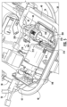
- Fig. 18 provides a top-down view of an exemplary embodiment of apparatus 10.
- Fig. 18 may omit various components or structures for the sake of clarity, such as an energy transfer attachment and electrical conduit that may extend to and position at wing 154.
- outer body 11 forms a wing 152, 154 extending from sides of the apparatus 10.
- Wing 152, 154 is configured to provide a latch interface or connection interface 156 at which energy transfer attachments 52, 54 may couple and secure onto outer body 11.
- Embodiments of outer body 11 may include a first wing 152 extending from the first side 15 and a second wing 154 extending from the second side 16.
- Each wing 152, 154 may include a first portion 153 extending outward from respective sides 15, 16. Wing 152, 154 may include a second portion 155 extending substantially co-directional or parallel to sides 15, 16. In some embodiments, interface 156 extends substantially co-directional or parallel to sides 15, 16 and corresponding to an extension of terminal interface 251 at the energy transfer attachment 250. In some embodiments, the interface 156 extends between second portion 155 and the respective side 15, 16 from which the wing 152, 154 is extended. Interface 156 may form a platform providing a surface at which connection ends 256 of respective energy transfer attachments 52, 54 may clamp and affix to outer body 11. In some embodiments, wings 152, 154 are formed integrally from one or both of outer cover 12 and base 14.
- Wings 152, 154 may each form recesses, grooves, or textured surfaces configured to retain energy transfer attachments 52, 54, such as connection ends 256, onto outer body 11.
- interface 156 may be recessed relative to first portion 153, second portion 155, or both.
- interface 156 may form a platform at which grooves or recesses are formed. Grooves or recesses at the interface 156 may extend co-directional to an extension of the energy transfer attachment 250 (e.g., co-directional to an extension between first end 201 and second end 202 at the energy transfer attachment 250.
- Embodiments of the apparatus 10 depicted and described herein provide an energy transfer device, such as a portable battery booster or jump starter, combined with an air supply device, such as an inflator, within a single, compact package.
- Embodiments provided herein may be configured to utilize energy from capacitor 60, an external battery or energy cell connected at power supply port 34, or both, to provide energy to, e.g., a vehicle battery, via energy transfer attachments 52, 54.
- Capacitor 60, external battery or energy cell connected at power supply port 34, or both may further provide energy to operate the air supply device or pump assembly 100 including motor 150, transmission system 200, and piston assembly 300.
- collar assembly 320 provides a flowpath for receiving and pumping air through air supply conduit 40, and furthermore a mount structure for retaining and receiving piston sleeve 310. Embodiments of collar assembly 320 furthermore provide a mount structure for housing 308 and various components of transmission system 200. Embodiments of collar assembly 320, piston sleeve 310, and housing 308 allow for combining an air supply device and battery booster within interior 22 of apparatus 10 into a compact, portable unit. Embodiments of energy transfer attachment 250 provided herein may prevent shock or other undesired energy transfer to user or through pathways other than terminal interface 251.
- air supply devices and components thereof may generally include fluid supply devices.
Landscapes
- Engineering & Computer Science (AREA)
- Mechanical Engineering (AREA)
- General Engineering & Computer Science (AREA)
- Power Engineering (AREA)
- Chemical & Material Sciences (AREA)
- Transportation (AREA)
- Combustion & Propulsion (AREA)
- Manufacturing & Machinery (AREA)
- Computer Networks & Wireless Communication (AREA)
- Chemical Kinetics & Catalysis (AREA)
- Electrochemistry (AREA)
- General Chemical & Material Sciences (AREA)
- Compressors, Vaccum Pumps And Other Relevant Systems (AREA)
- Arrangement Or Mounting Of Propulsion Units For Vehicles (AREA)
- Hydraulic Motors (AREA)
- Reciprocating Pumps (AREA)
Abstract
Description
- The present disclosure relates generally to battery booster or jump starter devices, and more particularly to portable battery booster or jump starter devices.
- Portable battery booster and jump starter devices are used for providing energy to a battery, such as to start a vehicle or to charge a vehicle battery. Additional vehicle issues may include loss of tire pressure, requiring air to be supplied to a tire. Separate devices may be utilized for supplying air and energy. However, utilizing separate devices requires a user to ensure that each device has stored energy for operating each device. Accordingly, there is a need for apparatuses and structures for battery booster and air supply devices.
- Aspects and advantages of the invention in accordance with the present disclosure will be set forth in part in the following description, or may be understood from the description, or may be learned through practice of the technology.
- An aspect of the present disclosure is directed to a fluid and power provision apparatus. The apparatus includes a power provision device and a pump assembly. The pump assembly includes a motor, a transmission system, a piston assembly, and a collar assembly. The piston assembly includes a piston sleeve, a piston, and a piston arm operably coupled to the piston and the transmission system to transmit energy from the motor to articulate the piston within the piston sleeve. The collar assembly forms a collar plenum, a first flowpath, and a second flowpath. The piston sleeve extends at least in part into the collar plenum. The first flowpath extends in fluid communication from the collar plenum to a fluid supply outlet. The second flowpath extends in fluid communication from an interior of the apparatus to the first flowpath.
- Another aspect of the present disclosure is directed to a battery booster and air supply apparatus. The apparatus includes a base at least partially forming an interior of the apparatus. A power provision device includes a capacitor positioned at the interior of the apparatus. The capacitor is configured to transfer energy through a pair of electrical conduits and respective energy transfer attachments. A fluid supply apparatus includes a pump assembly positioned at the interior of the apparatus. The pump assembly includes a motor, a transmission system, a piston assembly, and a collar assembly. An air supply conduit extending in fluid communication from the piston assembly. An attachment end is affixed to the air supply conduit distal to the pump assembly. The piston assembly includes a piston sleeve, a piston, and a piston arm operably coupled to the piston and the transmission system to transmit energy from the motor to articulate the piston within the piston sleeve. The collar assembly forms a collar plenum, a first flowpath, and a second flowpath. The piston sleeve extends at least in part into the collar plenum. The first flowpath extends in fluid communication from the collar plenum to the air supply conduit. The second flowpath extends in fluid communication from an interior of the apparatus to the first flowpath.
- Yet another aspect of the present disclosure is directed to a battery booster apparatus. The apparatus includes an outer body forming an interior, wherein a wing forming a recessed platform extends from the outer body; and an energy transfer attachment operably coupled to an electrical conduit, the electrical conduit operably coupled to a power provision device positioned at the interior, the energy transfer attachment including a pair of clamp bodies connected in hinged arrangement at a hinge, the clamp body including a handle and a connection end, wherein the hinge is positioned between the handle and the connection end, and wherein a terminal interface including a conductive material is positioned at the connection end.
- These and other features, aspects and advantages of the present invention will become better understood with reference to the following description and appended claims. The accompanying drawings, which are incorporated in and constitute a part of this specification, illustrate embodiments of the technology and, together with the description, serve to explain the principles of the technology.
- A full and enabling disclosure of the present invention, including the best mode of making and using the present systems and methods, directed to one of ordinary skill in the art, is set forth in the specification, which makes reference to the appended figures, in which:
-
Fig. 1 is a perspective view of an embodiment of a fluid and power provision apparatus in accordance with aspects of the present disclosure; -
Fig. 2 is a perspective view of the apparatus ofFig. 1 in which an outer cover is transparent and depicting internal components of the apparatus in accordance with aspects of the present disclosure; -
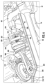
Fig. 3 is a detailed perspective view of a portion of the apparatus in accordance with aspects of the present disclosure; -
Fig. 4 is a detailed perspective view of a portion of the apparatus in accordance with aspects of the present disclosure; -
Fig. 5 is a detailed perspective view of a portion of the apparatus in accordance with aspects of the present disclosure; -
Fig. 6 is a detailed perspective view of a portion of the apparatus in accordance with aspects of the present disclosure; -
Fig. 7 is a detailed perspective view of a portion of the apparatus in accordance with aspects of the present disclosure; -
Fig. 8 is a perspective view of a collar assembly of the apparatus in accordance with aspects of the present disclosure; -
Fig. 9 is a cutaway perspective view of the collar assembly ofFig. 7 in accordance with aspects of the present disclosure; -
Fig. 10 is a cutaway perspective view of the collar assembly ofFig. 7 in accordance with aspects of the present disclosure; -
Fig. 11 is a perspective view of a portion of the apparatus in accordance with aspects of the present disclosure; -
Fig. 12 is a perspective view of a portion of the apparatus in accordance with aspects of the present disclosure; -
Fig. 13 is a perspective view of a portion of the apparatus in accordance with aspects of the present disclosure; -
Fig. 14 is a perspective view of a portion of the apparatus in accordance with aspects of the present disclosure; -
Fig. 15 is a perspective view of an exemplary embodiment of an energy transfer attachment in accordance with aspects of the present disclosure; -
Fig. 16 is a see-through perspective view of an exemplary embodiment of an energy transfer attachment in accordance with aspects of the present disclosure; -
Fig. 17 is a cross-sectional perspective view of the energy transfer attachment ofFig. 15 in accordance with aspects of the present disclosure; and -
Fig. 18 is a top-down view of an exemplary embodiment of a fluid and power provision apparatus in accordance with aspects of the present disclosure. - Repeat use of reference characters in the present specification and drawings is intended to represent the same or analogous features or elements of the present invention.
- Reference now will be made in detail to embodiments of the present invention, one or more examples of which are illustrated in the drawings. The word "exemplary" is used herein to mean "serving as an example, instance, or illustration." Any implementation described herein as "exemplary" is not necessarily to be construed as preferred or advantageous over other implementations. Moreover, each example is provided by way of explanation, rather than limitation of, the technology. In fact, it will be apparent to those skilled in the art that modifications and variations can be made in the present technology without departing from the scope or spirit of the claimed technology. For instance, features illustrated or described as part of one embodiment can be used with another embodiment to yield a still further embodiment. Thus, it is intended that the present disclosure covers such modifications and variations as come within the scope of the appended claims and their equivalents. The detailed description uses numerical and letter designations to refer to features in the drawings. Like or similar designations in the drawings and description have been used to refer to like or similar parts of the invention.
- As used herein, the terms "first", "second", and "third" may be used interchangeably to distinguish one component from another and are not intended to signify location or importance of the individual components. The singular forms "a," "an," and "the" include plural references unless the context clearly dictates otherwise. The terms "coupled," "fixed," "attached to," and the like refer to both direct coupling, fixing, or attaching, as well as indirect coupling, fixing, or attaching through one or more intermediate components or features, unless otherwise specified herein. As used herein, the terms "comprises," "comprising," "includes," "including," "has," "having" or any other variation thereof, are intended to cover a non-exclusive inclusion. For example, a process, method, article, or apparatus that comprises a list of features is not necessarily limited only to those features but may include other features not expressly listed or inherent to such process, method, article, or apparatus. Further, unless expressly stated to the contrary, "or" refers to an inclusive- or and not to an exclusive- or. For example, a condition A or B is satisfied by any one of the following: A is true (or present) and B is false (or not present), A is false (or not present) and B is true (or present), and both A and B are true (or present).
- Terms of approximation, such as "about," "generally," "approximately," or "substantially," include values within ten percent greater or less than the stated value. When used in the context of an angle or direction, such terms include within ten degrees greater or less than the stated angle or direction. For example, "generally vertical" includes directions within ten degrees of vertical in any direction, e.g., clockwise or counter-clockwise.
- Benefits, other advantages, and solutions to problems are described below with regard to specific embodiments. However, the benefits, advantages, solutions to problems, and any feature(s) that may cause any benefit, advantage, or solution to occur or become more pronounced are not to be construed as a critical, required, or essential feature of any or all the claims.
- Embodiments of a combined air and power provision apparatus are provided. Embodiments of the apparatus depicted and described herein include structures allowing for including a pump assembly and an energy or power provision device into an interior of a single, portable apparatus. Embodiments of apparatuses such as provided herein include portable, relatively compact, and lightweight battery booster and air supply devices that may allow for stored energy to operate each of a battery booster device and an air supply device.
- Referring to the drawings,
Fig. 1 provides a perspective view of an embodiment of an air andpower provision apparatus 10.Fig. 2 provides a perspective view of theapparatus 10 ofFig. 1 in which anouter cover 12 is removed and allowing components within an interior 22 of theapparatus 10 to be viewed. Anouter body 11 forms interior 22 at which operational components for a power provision device 90 and apump assembly 100 are provided.Outer body 11 generally includes a base 14 forming walls extending between afirst side 15 and asecond side 16 laterally separated from one another and afirst end 17 and asecond end 18 longitudinally separated from one another.Base 14 may form a trough or basket including mounting features, snaps, fastener openings, or other retainer features configured to receive, retain, mount, or otherwise secure components within interior 22 (Fig. 2 ). - The
outer body 11 ofapparatus 10 includesbase 14 andouter cover 12 together substantially enclosing interior 22 (Fig. 2 ) and components generally positioned or secured withininterior 22. Theouter cover 12 may further include aseparable controller cover 24.Controller cover 24 includescontrol interfaces 26 operably coupled acontroller 38 configured to command operation of electrical and electronic components of theapparatus 10, such as further described herein. Control interfaces 26 may include buttons, switches, touchscreen interfaces, or other control surfaces.Control cover 24 may further include acommunications port 28. Thecommunications port 28 includes any appropriate interface for receiving, transmitting, or both, signals to or from electrical and electronic components or controllers. In some embodiments,communications port 28 forms any appropriate type of universal serial bus (USB) port, or other type of communications interface. -
Controller cover 24 may further include adisplay screen 30 configured to provide visual signal to a user, such as signals communicating to the user an operating mode (e.g., power provision mode or air supply mode), an operating state (e.g., standby, discharging energy, receiving energy, voltage determination, operating errors, etc.), an on/off status, or other applicable indications of operation, state, health, safety, or function at theapparatus 10 or devices operably attached toapparatus 10, such as a vehicle battery, a power supply, or vessel configured to receive air (e.g., a vehicle tire, an inflatable structure, etc.). -
Outer cover 12 may form apower supply interface 32 configured to receive a power supply. Thepower supply interface 32 includes apower supply port 34 configured to receive an energy cell, battery, capacitor, or energy input plug. In a particular embodiment, thepower supply interface 32 includes retention features 36, such as snaps or clips, configured to receive a detachable energy cell or battery. In some embodiments, the power supply includes an 18-volt lithium ion battery. In other embodiments, any appropriate voltage or amperage power supply may be utilized. - Referring to
Figs. 1-2 ,apparatus 10 may further include astrap 19 extending frombase 14. Further embodiments ofapparatus 10 may include aclip 21 extending frombase 14. In the embodiment depicts inFigs. 1-2 ,strap 19 extends from thesecond end 18 ofapparatus 10 andclip 21 extends fromfirst end 17. In various embodiments,clip 21 extends from any desired location along which anair supply conduit 40 extends from interior 22 to anattachment end 42.Clip 21 is configured to releasably affixair supply conduit 40 to an exterior ofapparatus 10.Attachment end 42 may form any appropriate fitting for attaching to a valve to provide air to a vessel, such as a vessel forming a tire or tube, ball, or inflatable device. In various embodiments, attachment end 42 forms a Presta valve (e.g., PV valve), a French valve (e.g., FV valve), a Sclaverand valve, a diverter valve (e.g., DV valve), a Schrader valve (e.g., SV valve), an American valve (e.g., AV valve), a Dunlop valve, or other appropriate type of valve or flow control device. - Referring still to
Figs. 1-2 ,apparatus 10 includes a pair ofenergy transfer attachments attachments respective attachment electrical conduit capacitor 60 and theenergy transfer attachments energy transfer attachment 52 may form a positive terminal and a secondenergy transfer attachment 54 may form a negative terminal. However, it should be appreciated that the firstenergy transfer attachment 52 may form a negative terminal and the secondenergy transfer attachment 54 may form a positive terminal. - In various embodiments,
capacitor 60 is a device configured to store electrical energy. In particular embodiments,capacitor 60 is a passive electronic component including terminals and configured to store electrical energy in an electric field.Capacitor 60 may include any appropriate type of electrical conductor, such as, but not limited to, metallic surfaces separated by a dielectric medium.Capacitor 60 may include any type of conductor and dielectric medium suitable for portable vehicle starters or chargers. Energy stored bycapacitor 60 is selectively releasable throughconduits energy transfer attachments - Referring now to
Figs. 3-4 , detailed perspective views of a portion of theapparatus 10 depict apump assembly 100. In various embodiments,pump assembly 100 includes amotor 150 operably coupled to apiston assembly 300 fluidly coupled toair supply conduit 40 to flow air through theair supply conduit 40 to theattachment end 42. In various embodiments,apparatus 10 may include afan 148 operably coupledmotor 150 to flow air, such as cooling air formotor 150 or electrical or electronic components atinterior 22, or air to be received intoair supply conduit 40, or both. In some embodiments,motor 150 is operably coupled to atransmission system 200 to transmit energy topiston assembly 300. Embodiments ofapparatus 10 are configured to transmit energy from the capacitor 60 (Fig. 2 ) to drivemotor 150. In some embodiments,motor 150 is operatively coupled totransmission system 200 to drivepiston assembly 300. In some embodiments,transmission system 200 includes agear 210 operably coupled tomotor 150 to receive energy from themotor 150 and transfer energy topiston assembly 300.Gear 210 may mesh at anoutput gear 212 rotatably coupled to an output shaft atmotor 150.Gear 210 is rotatable at acentral axis 216 by ashaft 214 extending throughgear 210.Shaft 214 is coupled to ahousing 308 to establishaxis 216. In particular,shaft 214 extends intohousing 308 and is allowed to rotate alongaxis 216.Gear 210 is coupled toshaft 214 to correspondingly rotate alongaxis 216 when energy frommotor 150 drives gear 210 viaoutput gear 212 and a gear mesh betweengears - Referring now to
Figs. 5-7 , perspective views of portions ofapparatus 10 including portions ofpump assembly 100 are provided.Figs. 5-7 omit for the sake of clarity some components otherwise depicted inFigs. 1-4 . Referring toFigs. 1-7 ,piston assembly 300 includes apiston sleeve 310 forming a piston chamber 312 (Fig. 3 ) within thepiston sleeve 310.Piston assembly 300 includes apiston 302 connected to apiston arm 304.Piston arm 304 is operably coupled totransmission system 200 to receive motive energy to articulate thepiston 302 within thepiston chamber 312 formed bypiston sleeve 310. In some embodiments,piston arm 304 is coupled to gear 210 throughrotatable shaft 218.Shaft 218 is positioned off-center fromaxis 216 atgear 210, such as to allowshaft 218 to rotate along a circumferential path aroundcentral axis 216.Piston arm 304 is allowed to move, such as to slide with movement ofshaft 218, to covert rotational movement of theshaft 218 andgear 310 to linear movement ofpiston arm 304 andpiston 302 withinpiston sleeve 310. - In some embodiments,
piston sleeve 310 andhousing 308 together form a unitary, monolithic body. Accordingly, the unitary, monolithic body includes a substantiallycylindrical piston sleeve 310 portion through whichpiston 302 andpiston arm 304 extend and ahousing 308 portion into whichshaft 214 is supported. The unitary monolithic body may further include one ormore mount interfaces 306 configured to affix toapparatus 10.Mount interface 306 may include an opening configured to receive a fastener, such as a screw, bolt, pin, tie-rod, or other mechanical fastener. In some embodiments,mount interface 306 is positioned adjacent tomotor 150 to allow a fastener to extend throughmount interface 306 to connect tomotor 150. In a still particular embodiment,mount interface 306 is connected to thehousing 308. It should be appreciated that additional or alternative mount interfaces may be included to couple, affix, or otherwisesecure housing 308 withininterior 22 ofapparatus 10. - Referring still to
Figs. 1-7 , and further depicted in detailed portions inFigs. 8-10 ,pump assembly 100 includes acollar assembly 320.Fig. 8 depicts an embodiment ofcollar assembly 320.Figs. 9-10 depict sectional views of the collar assembly ofFig. 8 , further displaying details further described herein. Referring toFigs. 1-7 ,collar assembly 320 at least partially surroundspiston sleeve 310. In various embodiments,collar assembly 320 includes a substantiallycylindrical portion 322 at least partially surroundingpiston sleeve 310 whenpiston sleeve 310 is positioned withincollar assembly 320. - Depicted in further detail in regard to
Figs. 8-10 ,collar assembly 320 forms afirst flowpath 324 extending in fluid communication from thecollar plenum 314 to an air supply outlet, such as at an interface of thefirst flowpath 324 and theair supply conduit 40. In some embodiments,collar assembly 320 includes afirst manifold 334 extending from thecylindrical portion 322.First manifold 334 forms an air supply outlet at a terminal end at whichair supply conduit 40 is connectable to thefirst manifold 334 to receive a flow of air frompump assembly 300.First manifold 334 forms, at least in part, thefirst flowpath 324. In some embodiments,cylindrical portion 322 forms a portion offirst flowpath 324. - In some embodiments,
collar assembly 320 forms asecond flowpath 326 extending in fluid communication to thefirst flowpath 324. In some embodiments,collar assembly 320 includes asecond manifold 336 extending from thefirst manifold 334. In still some embodiments,second manifold 336 forms thesecond flowpath 326. In various embodiments, an opening 338 is positioned to allow a flow of air to enter intosecond flowpath 326 and flow intofirst flowpath 324 and egress intoair supply conduit 40. In some embodiments, opening 338 is formed at thesecond manifold 336 and positioned in fluid communication withinterior 22 ofhousing 10. In another embodiment, opening 338 is positioned in fluid communication with an exterior ofhousing 10. - In various embodiments,
first manifold 334 forms afirst nozzle 344 at whichair supply conduit 40 is connectable to receive a flow of air frompump assembly 300. In still various embodiments,second manifold 336 forms asecond nozzle 346 through which air is received through opening 338 intosecond flowpath 326.First manifold 334 may form raisedsurfaces 342, such as walls or ridges, configured to receive a fitting 44 (Figs. 4-6 ) at a proximate end ofair supply conduit 40. Referring toFigs. 4-6 , fitting 44 may include any appropriate fastener configured to couple theair supply conduit 40 to thefirst manifold 334. In particular, fitting 44 is configured to attach toair supply conduit 40 and raisedsurfaces 342 secure a position of theair supply conduit 40 relative to thefirst manifold 334. In various embodiments, fitting 44 forms a ferrule or sleeve configured to crimp or press around theair supply conduit 40 and thefirst manifold 334. Raisedsurfaces 342,nozzle 344, or both may form surfaces at which fitting 44 is attachable. - Referring now to
Figs. 7-10 ,collar assembly 320 forms acollar plenum 314 at whichpiston sleeve 310 is received.Collar plenum 314 is formed, at least in part, bycylindrical portion 322 ofcollar assembly 320.Collar assembly 320 forms anend face 318 distal to an end at whichair supply conduit 40 attaches tofirst manifold 334. Referring toFigs. 7-8 ,collar assembly 320 forms a raised surface or key 319 extending radially into thecollar plenum 314.Key 319 atcollar assembly 320 corresponds to a groove 309 (Fig. 4 ) and key 329 (Fig. 14 ) atpiston sleeve 310.Groove 309 extends radially inward and along a circumferential arc, such as to form raised surface or key 329 at thepiston sleeve 310 within thecollar plenum 314. A stop wall is formed at ends of the arc formed atgroove 309. Assembly ofpiston sleeve 310 intocollar assembly 320 may include sliding thepiston sleeve 310 into thecollar plenum 314, and rotating thepiston sleeve 310 or thecollar assembly 320 to align thekeys Fig. 14 . In various embodiments (e.g., depicted inFig. 8 ), anopening 339 is formed along an arc at thecylindrical portion 322 ofcollar assembly 320. Opening 339 may allow groove 309 or key 329 atpiston sleeve 310, or particularly apiston cylinder 317 extending frompiston sleeve 310, to position alongsidekey 319 atcollar assembly 320. - Referring now to
Figs. 6-9 ,collar assembly 320forms teeth 354 configured to receive and retain a spring 350 (Figs. 6-7 ) withincollar plenum 314.Teeth 354 extend from anend wall 325 substantially co-directional to an extension ofspring 350.Teeth 354 are positioned around a fluid interface betweencollar plenum 314 andfirst flowpath 324.First flowpath 324 extends throughend wall 325 in fluid communication withcollar plenum 314. Perspective views of a sub-assembly of thecollar assembly 320,piston sleeve 310,housing 308, andspring 350 are provided inFigs. 11-13 .Piston sleeve 310 forms awall 313 forming anopening 315 through whichspring 350 at least partially extends.Wall 313 is positioned within thepiston sleeve 310, such as to form thepiston chamber 312 at a first side proximate to thepiston arm 304, and a second side proximate to thecollar assembly 320. In some embodiments,spring 350 attaches to wall 313. Asmotor 150 articulatespiston arm 304 andpiston 302 withinpiston chamber 312, pressure changes force air to pump throughopening 315.Spring 350 may allow for reactive forces to allow thepiston sleeve 310 to maintain position, or articulate within a desired tolerance, relative tocollar assembly 320. Pressure changes from articulation ofpiston 302 withinpiston chamber 312 cause air to pull throughsecond flowpath 326 and intofirst flowpath 324 to theair supply conduit 40. - In various embodiments,
collar assembly 320 is formed as a single, unitary, monolithic component. In some embodiments,collar assembly 320 includescylindrical portion 322,first manifold 334, andsecond manifold 336 formed as a unitary, monolithic component. In still particular embodiments,collar assembly 320 includescylindrical portion 322,first manifold 334,second manifold 336,nozzles Collar assembly 320 may be formed from any appropriate molding, extrusion, or additive process, or a machining process, or combinations thereof. - Referring to
Fig. 13 ,piston sleeve 310 may further include apiston cylinder 317 extending fromwall 313 into thecollar plenum 314.Piston cylinder 317 further attaches at anend 321 tocollar assembly 320 at end wall 325 (Fig. 9 ). As further depicted inFigs. 5-7 , aseal 352 may be positioned atend wall 325 aroundspring 350 andteeth 354.Fig. 13 further depictspiston cylinder 317 extending into thecollar plenum 314 and forming apiston plenum 327 within thepiston cylinder 317.Piston plenum 327 extends fromwall 313 to an interface withend wall 325 atcollar assembly 320.Spring 350 extends within thepiston plenum 327.Spring 350 may expand and compress betweenwall 313 andend wall 325.Seal 352 may discourage or inhibit fluid leaks or fluid communication between thepiston plenum 327 and thesurrounding collar plenum 314. - Referring now to
Figs. 15-17 , perspective views of an embodiment of anenergy transfer attachment 250 is provided.Fig. 17 provides a cross-sectional view of a portion of theenergy transfer attachment 250 depicted inFig. 15 . Embodiments of theenergy transfer attachment 250 depicted and described in regard toFigs. 15-17 may form embodiments of theenergy transfer attachments Fig. 1 . Anelectrical conduit 252 is operably coupled to theenergy transfer attachment 250. Theelectrical conduit 252 may include any appropriate conductive material for transferring electrical energy.Electrical conduit 252 further includes any appropriate protective or insulative material substantially surrounding the conductive material. Embodiments ofelectrical conduit 252 depicted and described in regard toFigs. 15-17 may form embodiments of theelectrical conduit Fig. 1 . Accordingly, embodiments ofenergy transfer attachment 250 depicted inFigs. 15-17 may form a positive or negative terminal attachment. Furthermore, embodiments ofelectrical conduit 252 depicted inFigs. 15-17 may form respective positive or negative electrical conduits operably coupled to respective positive and negative terminal attachments formed asenergy transfer attachment 250. - Referring to
Figs. 15-16 , theenergy transfer attachment 250 includes aclamp body 257 having a lever end or handle 258 and aconnection end 256.Fig. 16 provides an exemplary see-through view of an embodiment of theenergy transfer attachment 250 in which components at least partially internal to theclamp body 257 are depicted in further exemplary detail. A pair ofclamp bodies 257 is connected in hinged arrangement to one another via ahinge 254. In some embodiments, hinge 254 is positioned between thehandle 258 and theconnection end 256. In still some embodiments,terminal interface 251 is positioned within theconnection end 256. For instance,terminal interface 251 includes any appropriate conductive material (e.g., copper) operably coupled to receive electrical energy fromelectrical conduit 252.Terminal interface 251 may form a plurality of teeth or edges. For instance,terminal interface 251 may form clamp or clip surfaces at which a conductive material attaches to a conductive material, such as at a battery, capacitor, or other appropriate structure for receiving energy from theenergy transfer attachment 250.Clamp body 257, includingconnection end 256 and handle 258, includes any appropriate protective or insulative material suitable for a user to touch theclamp body 257. - Referring still to
Figs. 15-16 , a referencefirst end 201 is defined proximate to theconnection end 256 and distal to thehandle 258. A referencesecond end 202 is defined proximate to thelever end 258 andelectrical conduit 252 and distal to theconnection end 256.Hinge 254 forms a pivot point separating theconnection end 256 and thehandle 258. In some embodiments,terminal interface 251 is positioned substantially or completely within theconnection end 256. Stated differently,terminal interface 251 is formed and positioned substantially betweenhinge 254 andfirst end 201. Handle 258, or generally a portion ofenergy transfer attachment 250 fromhinge 254 tosecond end 202, may be substantially absent of theterminal interface 251. - Additionally, as shown in
Fig. 15 , each of thehandles 258 is shaped such that an outer surface thereof is curved and convex. The curved and convex shape of thehandles 258 allows a user to stably grip theenergy transfer attachment 250 while preventing the user's hand from sliding forward towards theconnection end 256 of theenergy transfer attachment 250. Furthermore, each of thehandles 258 may include recesses that form a better gripping surface for the user's hand. According to one or more embodiments, each of thehandles 258 may include three oval-shaped recesses, although a person of ordinary skill in the art would understand that there may be a different number of recesses and each recess may be shaped differently from that shown inFig. 15 . Alternatively, instead of the recesses, projections may be formed on each of thehandles 258 to form a better gripping surface. - Referring now to the cross sectional view provided in
Fig. 17 , aterminal end 253 ofelectrical conduit 252 is positioned at or proximate to thefirst end 201. In some embodiments, hinge 254 includes a spring or hingestructure 255 configured to generate a clamping force to push connection ends 256 (Fig. 15 ) together and allow connection ends 256 to separate whenhandles 258 are forced toward one another.Electrical conduit 252 may extend along an axis fromsecond end 202 towardfirst end 201 co-planar or co-axial to hingestructure 255.Electrical conduit 252 may furthermore extend along the axis fromsecond end 202 towardfirst end 201 to the connection end 256 (Fig. 15 ). Accordingly,terminal end 253 may extend to theconnection end 256 and operably couple to terminal interface 251 (Fig. 15 ) at theconnection end 256. -
Fig. 18 provides a top-down view of an exemplary embodiment ofapparatus 10.Fig. 18 may omit various components or structures for the sake of clarity, such as an energy transfer attachment and electrical conduit that may extend to and position atwing 154. Referring back toFig. 1 , and further depicted inFig. 18 , in some embodiments,outer body 11 forms awing apparatus 10.Wing connection interface 156 at whichenergy transfer attachments outer body 11. Embodiments ofouter body 11 may include afirst wing 152 extending from thefirst side 15 and asecond wing 154 extending from thesecond side 16. Eachwing first portion 153 extending outward fromrespective sides Wing second portion 155 extending substantially co-directional or parallel tosides interface 156 extends substantially co-directional or parallel tosides terminal interface 251 at theenergy transfer attachment 250. In some embodiments, theinterface 156 extends betweensecond portion 155 and therespective side wing Interface 156 may form a platform providing a surface at which connection ends 256 of respectiveenergy transfer attachments outer body 11. In some embodiments,wings outer cover 12 andbase 14.Wings energy transfer attachments outer body 11. In some embodiments,interface 156 may be recessed relative tofirst portion 153,second portion 155, or both. For instance,interface 156 may form a platform at which grooves or recesses are formed. Grooves or recesses at theinterface 156 may extend co-directional to an extension of the energy transfer attachment 250 (e.g., co-directional to an extension betweenfirst end 201 andsecond end 202 at theenergy transfer attachment 250. - Embodiments of the
apparatus 10 depicted and described herein provide an energy transfer device, such as a portable battery booster or jump starter, combined with an air supply device, such as an inflator, within a single, compact package. Embodiments provided herein may be configured to utilize energy fromcapacitor 60, an external battery or energy cell connected atpower supply port 34, or both, to provide energy to, e.g., a vehicle battery, viaenergy transfer attachments Capacitor 60, external battery or energy cell connected atpower supply port 34, or both, may further provide energy to operate the air supply device or pumpassembly 100 includingmotor 150,transmission system 200, andpiston assembly 300. In some embodiments,collar assembly 320 provides a flowpath for receiving and pumping air throughair supply conduit 40, and furthermore a mount structure for retaining and receivingpiston sleeve 310. Embodiments ofcollar assembly 320 furthermore provide a mount structure forhousing 308 and various components oftransmission system 200. Embodiments ofcollar assembly 320,piston sleeve 310, andhousing 308 allow for combining an air supply device and battery booster withininterior 22 ofapparatus 10 into a compact, portable unit. Embodiments ofenergy transfer attachment 250 provided herein may prevent shock or other undesired energy transfer to user or through pathways other thanterminal interface 251. - While various embodiments depicted and described herein include components, structures, assemblies, devices, or apparatuses configured to receive, pump, and flow air, it should be appreciated that gaseous fluids generally may be received, pumped, and flowed. Accordingly, air supply devices and components thereof may generally include fluid supply devices.
- Further aspects and embodiments of the present subject matter are provided in the following clauses:
- 1. A fluid and power provision apparatus, the apparatus including a power provision device; a pump assembly, the pump assembly including a motor, a transmission system, a piston assembly, and a collar assembly, wherein the piston assembly includes a piston sleeve, a piston, and a piston arm operably coupled to the piston and the transmission system to transmit energy from the motor to articulate the piston within the piston sleeve, wherein the collar assembly forms a collar plenum, a first flowpath, and a second flowpath, the piston sleeve extending at least in part into the collar plenum, the first flowpath extending in fluid communication from the collar plenum to a fluid supply outlet, the second flowpath extending in fluid communication from an interior of the apparatus to the first flowpath.
- 2. The apparatus of any one or more clauses herein, wherein the collar assembly includes a first manifold forming the first flowpath, and wherein the collar assembly includes a second manifold forming the second flowpath.
- 3. The apparatus of any one or more clauses herein, wherein the collar assembly includes a cylindrical portion forming the collar plenum, and wherein the first manifold extends from the cylindrical portion.
- 4. The apparatus of any one or more clauses herein, wherein the second manifold extends from the first manifold.
- 5. The apparatus of any one or more clauses herein, wherein the first manifold, the second manifold, and the cylindrical portion form a unitary, monolithic component.
- 6. The apparatus of any one or more clauses herein, the piston assembly including a housing, the housing configured to support at least a portion of the transmission system.
- 7. The apparatus of any one or more clauses herein, wherein the housing and the piston sleeve form a unitary, monolithic component.
- 8. The apparatus of any one or more clauses herein, the transmission system including a gear operably coupled to an output gear at the motor; a first shaft coupled to a housing, wherein housing allows the first shaft to rotate along a central axis, and wherein the gear is operably coupled to the first shaft to allow rotation of the gear along the central axis.
- 9. The apparatus of any one or more clauses herein, wherein the piston arm is operably coupled to the gear through a second shaft coupled to the gear, wherein the second shaft is off-center from the central axis.
- 10. The apparatus of any one or more clauses herein, the power provision device including a capacitor configured to transfer energy through a pair of electrical conduits and respective energy transfer attachments.
- 11. The apparatus of any one or more clauses herein, the apparatus including a power supply interface, the power supply interface including a power supply port configured to receive an energy cell, battery, capacitor, or energy input plug.
- 12. The apparatus of any one or more clauses herein, wherein the collar assembly and the piston sleeve each form respective keys, wherein one or both of the collar assembly and the piston sleeve are configured to rotate to align the respective keys adjacent to one another.
- 13. The apparatus of any one or more clauses herein, wherein the piston sleeve includes a piston cylinder extending into the collar plenum, and wherein the key at the piston sleeve is positioned at the piston cylinder within the collar plenum.
- 14. The apparatus of any one or more clauses herein, the apparatus including a spring extending from an end wall of the collar assembly to a wall at the piston sleeve.
- 15. The apparatus of any one or more clauses herein, wherein the piston sleeve includes a piston cylinder extending from the wall at the piston sleeve into the collar plenum, and wherein the spring extends through a piston plenum formed within the piston cylinder.
- 16. A battery booster and air supply apparatus, the apparatus including a base at least partially forming an interior of the apparatus; a power provision device including a capacitor positioned at the interior of the apparatus, the capacitor configured to transfer energy through a pair of electrical conduits and respective energy transfer attachments; a fluid supply apparatus including a pump assembly positioned at the interior of the apparatus, the pump assembly including a motor, a transmission system, a piston assembly, and a collar assembly; an air supply conduit extending in fluid communication from the piston assembly, wherein an attachment end is affixed to the air supply conduit distal to the pump assembly, wherein the piston assembly includes a piston sleeve, a piston, and a piston arm operably coupled to the piston and the transmission system to transmit energy from the motor to articulate the piston within the piston sleeve, wherein the collar assembly forms a collar plenum, a first flowpath, and a second flowpath, the piston sleeve extending at least in part into the collar plenum, the first flowpath extending in fluid communication from the collar plenum to the air supply conduit, the second flowpath extending in fluid communication from an interior of the apparatus to the first flowpath.
- 17. The apparatus of any one or more clauses herein, wherein the collar assembly includes a first manifold forming the first flowpath, wherein the collar assembly includes a second manifold forming the second flowpath, and wherein the collar assembly includes a cylindrical portion forming the collar plenum, and wherein the first manifold extends from the cylindrical portion, and wherein the first manifold, the second manifold, and the cylindrical portion form a unitary, monolithic component.
- 18. The apparatus of any one or more clauses herein, the piston assembly including a housing formed with the piston sleeve as a unitary, monolithic component, the housing configured to support at least a portion of the transmission system.
- 19. The apparatus of any one or more clauses herein, the transmission system including a gear operably coupled to an output gear at the motor; a first shaft coupled to a housing, wherein housing allows the first shaft to rotate along a central axis, wherein the gear is operably coupled to the first shaft to allow rotation of the gear along the central axis, and wherein the piston arm is operably coupled to the gear through a second shaft coupled to the gear, wherein the second shaft is off-center from the central axis.
- 20. The apparatus of any one or more clauses herein, wherein the piston sleeve includes a piston cylinder extending from a wall at the piston sleeve into the collar plenum, and wherein a spring extends through a piston plenum formed within the piston cylinder, and wherein the apparatus includes the spring extending within the piston plenum from an end wall of the collar assembly to the wall at the piston sleeve.
- 21. A battery booster apparatus, the apparatus including an outer body forming an interior, wherein a wing forming a recessed platform extends from the outer body; and an energy transfer attachment operably coupled to an electrical conduit, the electrical conduit operably coupled to a power provision device positioned at the interior, the energy transfer attachment including a pair of clamp bodies connected in hinged arrangement at a hinge, the clamp body including a handle and a connection end, wherein the hinge is positioned between the handle and the connection end, and wherein a terminal interface including a conductive material is positioned at the connection end.
- 22. The battery booster apparatus of any one or more clauses herein, including the battery booster and air supply apparatus of any one or more clauses herein.
- 23. The battery booster apparatus of any one or more clauses herein, including the fluid and power provision apparatus of any one or more clauses herein.
- 24. The fluid and power provision apparatus of any one or more clauses herein, including the battery booster apparatus of any one or more clauses herein.
- 25. The battery booster and air supply apparatus of any one or more clauses herein, including the fluid and power provision apparatus of any one or more clauses herein.
- 26. An apparatus including the battery booster apparatus, the battery booster and air supply apparatus, or the fluid and power provision apparatus of any one or more clauses herein.
- This written description uses examples to disclose the invention, including the best mode, and also to enable any person skilled in the art to practice the invention, including making and using any devices or systems and performing any incorporated methods. The patentable scope of the invention is defined by the claims, and may include other examples that occur to those skilled in the art. Such other examples are intended to be within the scope of the claims if they include structural elements that do not differ from the literal language of the claims, or if they include equivalent structural elements with insubstantial differences from the literal language of the claims.
Claims (15)
- A fluid and power provision apparatus (10), the apparatus (10) comprising:a power provision device (90);a pump assembly (100), the pump assembly (100) comprising a motor (150), a transmission system (200), a piston assembly (300), and a collar assembly (320),wherein the piston assembly (300) comprises a piston sleeve (310), a piston (302), and a piston arm (304) operably coupled to the piston (302) and the transmission system (200) to transmit energy from the motor (150) to articulate the piston (302) within the piston sleeve (310),wherein the collar assembly (320) forms a collar plenum (314), a first flowpath (324), and a second flowpath (326), the piston sleeve (310) extending at least in part into the collar plenum (314), the first flowpath (324) extending in fluid communication from the collar plenum (314) to a fluid supply outlet, the second flowpath (326) extending in fluid communication from an interior (22) of the apparatus (10) to the first flowpath (324).
- The apparatus (10) of claim 1, wherein the collar assembly (320) comprises a first manifold (334) forming the first flowpath (324), and wherein the collar assembly (320) comprises a second manifold (336) forming the second flowpath (326).
- The apparatus (10) of claim 2, wherein the collar assembly (320) comprises a cylindrical portion (322) forming the collar plenum (314), and wherein the first manifold (334) extends from the cylindrical portion (322).
- The apparatus (10) of claim 3, wherein the second manifold (336) extends from the first manifold (334).
- The apparatus (10) of claim 3, wherein the first manifold (334), the second manifold (336), and the cylindrical portion (322) form a unitary, monolithic component.
- The apparatus (10) of claim 1, the piston assembly (300) comprising a housing (308), the housing (308) configured to support at least a portion of the transmission system (200).
- The apparatus (10) of claim 6, wherein the housing (308) and the piston sleeve (310) form a unitary, monolithic component.
- The apparatus (10) of claim 1, the transmission system (200) comprising:a gear (210) operably coupled to an output gear (212) at the motor (150);a first shaft (214) coupled to a housing (308), wherein housing (308) allows the first shaft (214) to rotate along a central axis, and wherein the gear (210) is operably coupled to the first shaft (214) to allow rotation of the gear (210) along the central axis.
- The apparatus (10) of claim 8, wherein the piston arm (304) is operably coupled to the gear (210) through a second shaft (218) coupled to the gear (210), wherein the second shaft (218) is off-center from the central axis.
- The apparatus (10) of claim 1, wherein the collar assembly (320) and the piston sleeve (310) each form respective keys (319), wherein one or both of the collar assembly (320) and the piston sleeve (310) are configured to rotate to align the respective keys (319) adjacent to one another.
- The apparatus (10) of claim 10, wherein the piston sleeve (310) comprises a piston cylinder (317) extending into the collar plenum (314), and wherein the key (319) at the piston sleeve (310) is positioned at the piston cylinder (317) within the collar plenum (314).
- The apparatus (10) of claim 1, the apparatus (10) comprising:
a spring (350) extending from an end wall (325) of the collar assembly (320) to a wall (313) at the piston sleeve (310). - The apparatus (10) of claim 12, wherein the piston sleeve (310) comprises a piston cylinder (317) extending from the wall (313) at the piston sleeve (310) into the collar plenum (314), and wherein the spring (350) extends through a piston plenum (327) formed within the piston cylinder (317).
- The apparatus (10) of claim 1, the apparatus (10) wherein the power provision device (90) comprises a capacitor (60) configured to transfer energy through a pair of electrical conduits (252) and respective energy transfer attachments (52), (54).
- The apparatus (10) of claim 1, comprising:an outer body (11);a wing (152), (154) forming a recessed platform (156) extending from the outer body (11); andan energy transfer attachment (250) operably coupled to an electrical conduit (252), the electrical conduit (252) operably coupled to a power provision device (90) positioned at the interior (22), the energy transfer attachment (250) comprising a pair of clamp bodies (257) connected in hinged arrangement at a hinge (254), the clamp body (257) comprising a handle (258) and a connection end (256), wherein the hinge (254) is positioned between the handle (258) and the connection end (256), and wherein a terminal interface (251) comprising a conductive material is positioned at the connection end (256)..
Priority Applications (1)
| Application Number | Priority Date | Filing Date | Title |
|---|---|---|---|
| EP25227472.5A EP4717919A1 (en) | 2022-10-11 | 2023-10-10 | Fluid and power provision apparatus |
Applications Claiming Priority (1)
| Application Number | Priority Date | Filing Date | Title |
|---|---|---|---|
| US17/963,307 US12368315B2 (en) | 2022-10-11 | 2022-10-11 | Fluid and power provision apparatus |
Related Child Applications (1)
| Application Number | Title | Priority Date | Filing Date |
|---|---|---|---|
| EP25227472.5A Division EP4717919A1 (en) | 2022-10-11 | 2023-10-10 | Fluid and power provision apparatus |
Publications (3)
| Publication Number | Publication Date |
|---|---|
| EP4353971A1 true EP4353971A1 (en) | 2024-04-17 |
| EP4353971B1 EP4353971B1 (en) | 2025-12-31 |
| EP4353971C0 EP4353971C0 (en) | 2025-12-31 |
Family
ID=88315379
Family Applications (2)
| Application Number | Title | Priority Date | Filing Date |
|---|---|---|---|
| EP23202842.3A Active EP4353971B1 (en) | 2022-10-11 | 2023-10-10 | FLUID AND POWER SUPPLY DEVICE |
| EP25227472.5A Pending EP4717919A1 (en) | 2022-10-11 | 2023-10-10 | Fluid and power provision apparatus |
Family Applications After (1)
| Application Number | Title | Priority Date | Filing Date |
|---|---|---|---|
| EP25227472.5A Pending EP4717919A1 (en) | 2022-10-11 | 2023-10-10 | Fluid and power provision apparatus |
Country Status (5)
| Country | Link |
|---|---|
| US (2) | US12368315B2 (en) |
| EP (2) | EP4353971B1 (en) |
| CN (1) | CN117869251A (en) |
| AU (1) | AU2023248105A1 (en) |
| CA (1) | CA3215806A1 (en) |
Families Citing this family (2)
| Publication number | Priority date | Publication date | Assignee | Title |
|---|---|---|---|---|
| USD1050018S1 (en) * | 2020-11-04 | 2024-11-05 | Techtronic Floor Care Technology Limited | Charger |
| JP1796115S (en) * | 2024-03-12 | 2025-04-15 | Start-up power supply |
Citations (5)
| Publication number | Priority date | Publication date | Assignee | Title |
|---|---|---|---|---|
| US5931207A (en) * | 1997-03-05 | 1999-08-03 | Gianino; Rosario N. | Portable home and garden sprayer, power unit |
| US6716003B2 (en) * | 2002-05-06 | 2004-04-06 | Chih-Ming Chen | Structure for an air pump |
| WO2017015711A1 (en) * | 2015-07-27 | 2017-02-02 | Walmsley Developments Pty Ltd | Portable pump |
| US20220123581A1 (en) * | 2020-10-20 | 2022-04-21 | Schumacher Electric Corporation | Battery Booster |
| WO2022197731A1 (en) * | 2021-03-15 | 2022-09-22 | The Noco Company | Portable jump starter and air compressor device |
Family Cites Families (94)
| Publication number | Priority date | Publication date | Assignee | Title |
|---|---|---|---|---|
| EP0258776B1 (en) * | 1986-09-02 | 1992-01-22 | Keller, Gotthold | Starting aid cable |
| US4902955A (en) | 1988-10-31 | 1990-02-20 | Manis Donald R | Portable battery charger |
| WO1994028609A1 (en) | 1991-12-31 | 1994-12-08 | Wells Mickey D | Jumper cable attachment for battery |
| CA2109166C (en) | 1993-10-25 | 2001-05-29 | Luc Rozon | Portable booster battery |
| US5793185A (en) | 1997-06-10 | 1998-08-11 | Deltona Transformer Corporation | Jump starter |
| US5982138A (en) | 1998-12-17 | 1999-11-09 | Vector Manufacturing, Ltd. | Portable electrical energy source |
| US6212054B1 (en) | 1999-09-21 | 2001-04-03 | Powerpro Inc. | Spark proof booster cable system |
| US6262560B1 (en) | 2000-07-17 | 2001-07-17 | Snap-On Technologies, Inc. | Battery pack discharge recovery circuit |
| US6788025B2 (en) | 2001-06-22 | 2004-09-07 | Midtronics, Inc. | Battery charger with booster pack |
| US7501795B2 (en) | 2001-06-22 | 2009-03-10 | Midtronics Inc. | Battery charger with booster pack |
| US6636015B1 (en) * | 2002-05-09 | 2003-10-21 | Team Products International Inc. | Watertight portable auxiliary power source |
| US6799993B2 (en) | 2002-12-20 | 2004-10-05 | Vector Products, Inc. | Portable electrical energy source |
| WO2004086535A2 (en) * | 2003-03-21 | 2004-10-07 | Vector Products, Inc. | Combination jump starter and high-frequency charger |
| US20060108970A1 (en) | 2003-06-11 | 2006-05-25 | Leasure Jeremy D | Integrated fuel cell system |
| US20050156564A1 (en) | 2003-06-23 | 2005-07-21 | Michael Krieger | Tool box power center |
| US6994599B2 (en) | 2004-02-10 | 2006-02-07 | Shurden Charles | Snag free cable clamp |
| CN2760832Y (en) | 2004-06-08 | 2006-02-22 | 吴月琴 | Power pack |
| CN101189434A (en) | 2005-02-18 | 2008-05-28 | 零件销售公司 | Small air compressor set |
| US20060244412A1 (en) * | 2005-05-02 | 2006-11-02 | Bon-Aire Industries, Inc. | Automotive jump-starter with polarity detection, current routing circuitry and lighted cable connection pairs |
| US20070247105A1 (en) | 2006-02-24 | 2007-10-25 | Black & Decker Inc. | Portable battery charger |
| US20070247108A1 (en) | 2006-04-21 | 2007-10-25 | Audley Brown | Portable battery charger |
| US8076900B1 (en) | 2006-04-21 | 2011-12-13 | Audley Brown | Portable battery charger |
| US7692402B2 (en) | 2006-12-21 | 2010-04-06 | Robert W. Wise | Emergency appliance system |
| US8653415B2 (en) | 2007-04-30 | 2014-02-18 | Illinois Tool Works Inc. | Engine-driven air compressor/generator load priority control system and method |
| US8759714B2 (en) | 2007-07-06 | 2014-06-24 | Illinois Tool Works Inc. | Portable generator and battery charger verification control method and system |
| US7795838B2 (en) | 2007-10-31 | 2010-09-14 | Chrysler Group Llc | User interface system and method for jump assist of hybrid vehicles |
| US20090230783A1 (en) * | 2008-03-10 | 2009-09-17 | Lane Austin Weed | Solar Portable Power Center |
| DE102008043852A1 (en) | 2008-11-19 | 2010-05-20 | Hilti Aktiengesellschaft Corporate Intellectual Property | Charger |
| US20110076168A1 (en) | 2009-03-24 | 2011-03-31 | Itt Manufacturing Enterprises, Inc | Portable inline pump kit |
| US20100301800A1 (en) | 2009-05-26 | 2010-12-02 | Mathew Inskeep | Multi-purpose battery jump starter and reconditioner |
| CN101749262B (en) | 2009-12-29 | 2011-12-28 | 佛山市顺德区新生源电器有限公司 | built-in electric air pump for air cushion bed |
| US20110298415A1 (en) | 2010-06-08 | 2011-12-08 | Guil Hetzroni | Jump starter and module power station |
| US8465594B1 (en) | 2010-06-10 | 2013-06-18 | Bronsson Harder | Battery jumper cables with integral wire brush |
| US9871392B2 (en) | 2010-09-17 | 2018-01-16 | Schumacher Electric Corporation | Portable battery booster |
| IL213824A (en) | 2011-06-28 | 2013-03-24 | Yaacov Shmuel Chaim Ben Aharon | System, method and apparatus for portable power supply |
| CN102496985B (en) | 2011-12-09 | 2014-05-28 | 雷星亮 | Portable backup power supply |
| US9643506B2 (en) | 2011-12-09 | 2017-05-09 | Shenzhen Carku Technology Co., Ltd. | Portable backup charger |
| US20140159509A1 (en) | 2012-09-11 | 2014-06-12 | Mathew Inskeep | Battery Boost Jump Starter |
| CN103066662B (en) | 2013-01-07 | 2015-08-05 | 雷星亮 | emergency power supply |
| CN203326656U (en) | 2013-06-27 | 2013-12-04 | 重庆市星海电子有限公司 | Innovation type vehicle-mounted multi-functional intelligent back-up power supply |
| US9506446B2 (en) | 2013-08-14 | 2016-11-29 | Spacekey (USA), Inc. | Mobile power bank |
| US9653933B2 (en) | 2013-11-12 | 2017-05-16 | Mathew Inskeep | Portable automotive battery jumper pack with detachable backup battery |
| CN103825331B (en) | 2014-03-03 | 2017-01-25 | 东莞市巨星电池有限公司 | Multifunctional automobile emergency starting power supply compatible with 12 voltages and 24 voltages |
| US20150306965A1 (en) | 2014-04-24 | 2015-10-29 | Munther Bader | Hand-powered jump starter for a vehicle |
| US9007015B1 (en) | 2014-07-03 | 2015-04-14 | The Noco Company | Portable vehicle battery jump start apparatus with safety protection |
| ES2860923T3 (en) | 2014-08-14 | 2021-10-05 | Schumacher Electric Corp | Compact multifunctional battery booster |
| CN104131961B (en) | 2014-08-19 | 2016-08-17 | 东莞瑞柯电子科技股份有限公司 | The Portable air compressor of power supply is started with removable multifunctional |
| US10075000B2 (en) | 2014-09-09 | 2018-09-11 | Halo International SEZC Ltd. | Safety circuit for multi-function portable power charger |
| US10141755B2 (en) | 2014-09-09 | 2018-11-27 | Halo International SEZC Ltd. | Multi-functional portable power charger |
| USD911936S1 (en) * | 2019-03-27 | 2021-03-02 | Halo International SEZC Ltd. | Portable power charger with air compressor hose |
| US9912183B2 (en) | 2015-03-13 | 2018-03-06 | Vanair Manufacturing, Inc. | Jump starter |
| WO2017066916A1 (en) | 2015-10-20 | 2017-04-27 | Unity Technology Development Corporation Limited | Start-up power sources, in particular for vehicle battery charging |
| CN106100010B (en) | 2016-05-17 | 2018-12-21 | 新昌县鼎瑞科技有限公司 | A kind of Vehicular multifunctional backup power source |
| US9797306B1 (en) | 2016-05-24 | 2017-10-24 | Jeff Stapleton | Portable generator |
| WO2018009515A2 (en) * | 2016-07-08 | 2018-01-11 | Edgeworks Innovations Llc | Multifunction unit including a power module |
| CN206116791U (en) | 2016-09-23 | 2017-04-19 | 东莞市仲康电子科技有限公司 | A car starting power supply with inverter |
| TWI621552B (en) | 2016-12-02 | 2018-04-21 | 姚立和 | Emergency start device for electric vehicle |
| WO2018183864A1 (en) | 2017-03-31 | 2018-10-04 | The Noco Company | Portable or hand held vehicle battery jump starting apparatus with battery cell equalization circuit |
| CA3070879C (en) | 2017-08-30 | 2023-04-04 | The Noco Company | Portable rechargeable battery jump starting device |
| US12074434B2 (en) * | 2017-09-22 | 2024-08-27 | The Noco Company | Portable vehicle battery jump starter with air pump |
| WO2019060135A1 (en) | 2017-09-22 | 2019-03-28 | The Noco Company | Rechargeable battery jump starting device with control switch backlight system |
| CN207382204U (en) | 2017-09-22 | 2018-05-18 | 杭州通利电器工具有限公司 | A kind of vehicle-mounted inverter of improved structure |
| CN207743908U (en) | 2017-11-06 | 2018-08-17 | 广州陆战旅户外装备制造有限公司 | Portable type solar energy outdoor power system |
| JP7018507B2 (en) | 2017-12-14 | 2022-02-10 | ザ・ノコ・カンパニー | Portable vehicle battery jump starter with air pump |
| CN208062856U (en) | 2018-04-20 | 2018-11-06 | 石兆科技有限公司 | A multifunctional vehicle emergency power supply |
| WO2019217983A1 (en) * | 2018-05-15 | 2019-11-21 | Startwarrior Ip Pty Ltd | An apparatus for spark-free starting of an internal combustion engine and method of operation thereof |
| US11069488B2 (en) | 2018-10-19 | 2021-07-20 | Systematic Power Solutions, LLC | Hybrid energy storage device |
| US11165266B2 (en) | 2018-10-19 | 2021-11-02 | Systematic Power Solutions, LLC | Method of providing charge for a mechanical object |
| CN113423947A (en) | 2018-10-29 | 2021-09-21 | Ox合作伙伴有限责任公司 | Detachable auxiliary power system |
| CN208874482U (en) | 2018-11-01 | 2019-05-17 | 深圳市新泰胜电子科技有限公司 | A portable inverter power supply |
| CN109217706A (en) | 2018-11-01 | 2019-01-15 | 深圳市新泰胜电子科技有限公司 | A kind of Portable inverter power source |
| CN209447975U (en) | 2018-11-13 | 2019-09-27 | 深圳市华思旭科技有限公司 | Electric tool power supply with vehicle launch function |
| CN209658261U (en) | 2019-04-01 | 2019-11-19 | 东莞博力威新能源有限公司 | A kind of ultra-thin energy storage battery case |
| JP7200033B2 (en) | 2019-04-10 | 2023-01-06 | Kyb株式会社 | Connectors and feeders |
| US20210040940A1 (en) * | 2019-08-05 | 2021-02-11 | Shi Qi ZHU | Portable Air Pump AMD Power Device |
| GB2607242B (en) | 2020-01-28 | 2025-04-30 | Noco Co | Jump starting device with enhanced (turbo) boost mode |
| CN111463851A (en) | 2020-04-01 | 2020-07-28 | 东莞市仲康电子科技有限公司 | Multifunctional automobile emergency starting power supply |
| US11647879B2 (en) | 2020-04-10 | 2023-05-16 | Shenzhen Chic Electrics Co. Ltd. | Multifunctional emergency starting power for motor vehicles |
| CN115461536B (en) | 2020-05-07 | 2023-05-23 | 米沃奇电动工具公司 | Vehicle battery jump starter with multiple battery pack compatibility |
| WO2022016234A1 (en) | 2020-07-23 | 2022-01-27 | Brown & Watson International Pty Ltd | Vehicle battery jump starter |
| CN114336924B (en) | 2020-09-27 | 2026-02-13 | 深圳市卡儿酷科技股份有限公司 | Control system, emergency jump starter and smart battery clamps |
| WO2022063275A1 (en) | 2020-09-27 | 2022-03-31 | 深圳市华思旭科技有限公司 | Control system, emergency starting power supply and intelligent battery clip |
| CN112260355A (en) | 2020-10-12 | 2021-01-22 | 深圳市科若视通科技有限公司 | Outdoor multifunctional emergency automobile starting power supply |
| EP4002639A1 (en) | 2020-11-19 | 2022-05-25 | Shenzhen Carku Technology Co., Limited | Smart connection device, start-up power supply, and battery clamp |
| CN216413934U (en) | 2020-11-25 | 2022-04-29 | 深圳市华思旭科技有限公司 | Energy storage power supply with multifunctional interface |
| CN114552684B (en) | 2020-11-25 | 2025-12-09 | 深圳市卡儿酷科技股份有限公司 | Energy storage power supply with multifunctional interface and working method |
| CN112688380B (en) | 2020-12-14 | 2023-05-30 | 广州引派旺汽车用品有限公司 | A car emergency starter power supply |
| CN113852262B (en) | 2020-12-18 | 2025-11-28 | 东莞市仲康电子科技有限公司 | Automobile starting power supply with voice prompt function and voice broadcasting method thereof |
| CN214479736U (en) | 2021-03-17 | 2021-10-22 | 东莞市立时电子有限公司 | Wireless multifunctional integrated machine for automobile starting power supply |
| CN214741917U (en) | 2021-04-29 | 2021-11-16 | 深圳市杰奇科技创新有限公司 | Starting power supply with inflator pump |
| CN214850575U (en) | 2021-05-29 | 2021-11-23 | 深圳市新驰客科技有限公司 | Emergency starting power supply with inflating function |
| CN215897489U (en) | 2021-08-11 | 2022-02-22 | 深圳市格瑞普电池有限公司 | A kind of emergency starting power supply for multi-function vehicle |
| CN216215968U (en) | 2021-10-09 | 2022-04-05 | 广州市车聚乐信息科技有限公司 | Multifunctional automobile emergency starting power supply |
| CN217010728U (en) | 2022-03-17 | 2022-07-19 | 深圳市卡莱福科技有限公司 | Vehicle emergency power supply device |
-
2022
- 2022-10-11 US US17/963,307 patent/US12368315B2/en active Active
-
2023
- 2023-10-10 CA CA3215806A patent/CA3215806A1/en active Pending
- 2023-10-10 EP EP23202842.3A patent/EP4353971B1/en active Active
- 2023-10-10 EP EP25227472.5A patent/EP4717919A1/en active Pending
- 2023-10-11 CN CN202311325143.5A patent/CN117869251A/en active Pending
- 2023-10-11 AU AU2023248105A patent/AU2023248105A1/en active Pending
-
2025
- 2025-06-30 US US19/254,707 patent/US20250330037A1/en active Pending
Patent Citations (5)
| Publication number | Priority date | Publication date | Assignee | Title |
|---|---|---|---|---|
| US5931207A (en) * | 1997-03-05 | 1999-08-03 | Gianino; Rosario N. | Portable home and garden sprayer, power unit |
| US6716003B2 (en) * | 2002-05-06 | 2004-04-06 | Chih-Ming Chen | Structure for an air pump |
| WO2017015711A1 (en) * | 2015-07-27 | 2017-02-02 | Walmsley Developments Pty Ltd | Portable pump |
| US20220123581A1 (en) * | 2020-10-20 | 2022-04-21 | Schumacher Electric Corporation | Battery Booster |
| WO2022197731A1 (en) * | 2021-03-15 | 2022-09-22 | The Noco Company | Portable jump starter and air compressor device |
Also Published As
| Publication number | Publication date |
|---|---|
| EP4717919A1 (en) | 2026-04-01 |
| US12368315B2 (en) | 2025-07-22 |
| EP4353971B1 (en) | 2025-12-31 |
| CA3215806A1 (en) | 2024-04-11 |
| AU2023248105A1 (en) | 2024-05-02 |
| US20250330037A1 (en) | 2025-10-23 |
| CN117869251A (en) | 2024-04-12 |
| EP4353971C0 (en) | 2025-12-31 |
| US20240120766A1 (en) | 2024-04-11 |
Similar Documents
| Publication | Publication Date | Title |
|---|---|---|
| US20250330037A1 (en) | Fluid and power provision apparatus | |
| US10946939B1 (en) | Watercraft having a waterproof container and a waterproof electrical connector | |
| US20190027720A1 (en) | Battery pack for a hand-held power tool | |
| US10780565B2 (en) | Housing device for a hand-held power tool | |
| EP4286679B1 (en) | Modular fuel transfer pump flow passage structure and fuel transfer pump | |
| WO2015157292A1 (en) | Multi-stage hydraulic tool | |
| EP4276976B1 (en) | Adapter, testing device, battery cell, battery, and electric apparatus | |
| CN114587182B (en) | Cleaning device and cleaning head thereof | |
| CN112134073A (en) | Cable quick connector | |
| CN213332695U (en) | Oil tank on-off valve, engine oil supply system and automobile | |
| CN210793592U (en) | Underwater robot | |
| CN114905914A (en) | Fluid control assembly and thermal management system | |
| CN217945458U (en) | Underwater propeller convenient to change conversion seat, diving device and water transport tool | |
| CN217864666U (en) | Many battery drive's underwater propulsor | |
| CN212257480U (en) | Battery module, power battery pack and portable battery-replacing electric vehicle | |
| CN210403787U (en) | Multifunctional battery pack and tool assembly using same | |
| CN217730742U (en) | Diving handle and underwater propeller | |
| CN223794822U (en) | Water nozzle, detachable joint assembly and battery system | |
| CN216121541U (en) | Electric clamping device and electric power robot | |
| CN218198788U (en) | Dual-control electric ship | |
| CN112847258B (en) | Handheld Power Tools | |
| CN223023378U (en) | Battery device and electric equipment | |
| CN220263112U (en) | Unmanned aerial vehicle organism socket subassembly | |
| EP1361020B1 (en) | Connection device for electric power and dust suction for a portable electrical tool for machining surfaces | |
| CN222589840U (en) | Robot joint driver interface structure, robot joint driver and robot |
Legal Events
| Date | Code | Title | Description |
|---|---|---|---|
| PUAI | Public reference made under article 153(3) epc to a published international application that has entered the european phase |
Free format text: ORIGINAL CODE: 0009012 |
|
| STAA | Information on the status of an ep patent application or granted ep patent |
Free format text: STATUS: THE APPLICATION HAS BEEN PUBLISHED |
|
| AK | Designated contracting states |
Kind code of ref document: A1 Designated state(s): AL AT BE BG CH CY CZ DE DK EE ES FI FR GB GR HR HU IE IS IT LI LT LU LV MC ME MK MT NL NO PL PT RO RS SE SI SK SM TR |
|
| STAA | Information on the status of an ep patent application or granted ep patent |
Free format text: STATUS: REQUEST FOR EXAMINATION WAS MADE |
|
| 17P | Request for examination filed |
Effective date: 20241017 |
|
| RBV | Designated contracting states (corrected) |
Designated state(s): AL AT BE BG CH CY CZ DE DK EE ES FI FR GB GR HR HU IE IS IT LI LT LU LV MC ME MK MT NL NO PL PT RO RS SE SI SK SM TR |
|
| GRAP | Despatch of communication of intention to grant a patent |
Free format text: ORIGINAL CODE: EPIDOSNIGR1 |
|
| STAA | Information on the status of an ep patent application or granted ep patent |
Free format text: STATUS: GRANT OF PATENT IS INTENDED |
|
| RIC1 | Information provided on ipc code assigned before grant |
Ipc: F04B 35/06 20060101AFI20250627BHEP Ipc: F04B 39/12 20060101ALI20250627BHEP Ipc: F04B 39/14 20060101ALI20250627BHEP Ipc: H02J 1/10 20060101ALI20250627BHEP |
|
| INTG | Intention to grant announced |
Effective date: 20250723 |
|
| GRAS | Grant fee paid |
Free format text: ORIGINAL CODE: EPIDOSNIGR3 |
|
| GRAA | (expected) grant |
Free format text: ORIGINAL CODE: 0009210 |
|
| STAA | Information on the status of an ep patent application or granted ep patent |
Free format text: STATUS: THE PATENT HAS BEEN GRANTED |
|
| AK | Designated contracting states |
Kind code of ref document: B1 Designated state(s): AL AT BE BG CH CY CZ DE DK EE ES FI FR GB GR HR HU IE IS IT LI LT LU LV MC ME MK MT NL NO PL PT RO RS SE SI SK SM TR |
|
| REG | Reference to a national code |
Ref country code: CH Ref legal event code: F10 Free format text: ST27 STATUS EVENT CODE: U-0-0-F10-F00 (AS PROVIDED BY THE NATIONAL OFFICE) Effective date: 20251231 Ref country code: GB Ref legal event code: FG4D |
|
| REG | Reference to a national code |
Ref country code: DE Ref legal event code: R096 Ref document number: 602023010358 Country of ref document: DE |
|
| REG | Reference to a national code |
Ref country code: IE Ref legal event code: FG4D |
|
| U01 | Request for unitary effect filed |
Effective date: 20260120 |
|
| U07 | Unitary effect registered |
Designated state(s): AT BE BG DE DK EE FI FR IT LT LU LV MT NL PT RO SE SI Effective date: 20260127 |
|
| PG25 | Lapsed in a contracting state [announced via postgrant information from national office to epo] |
Ref country code: NO Free format text: LAPSE BECAUSE OF FAILURE TO SUBMIT A TRANSLATION OF THE DESCRIPTION OR TO PAY THE FEE WITHIN THE PRESCRIBED TIME-LIMIT Effective date: 20260331 |
|
| PG25 | Lapsed in a contracting state [announced via postgrant information from national office to epo] |
Ref country code: HR Free format text: LAPSE BECAUSE OF FAILURE TO SUBMIT A TRANSLATION OF THE DESCRIPTION OR TO PAY THE FEE WITHIN THE PRESCRIBED TIME-LIMIT Effective date: 20251231 |
|
| PG25 | Lapsed in a contracting state [announced via postgrant information from national office to epo] |
Ref country code: RS Free format text: LAPSE BECAUSE OF FAILURE TO SUBMIT A TRANSLATION OF THE DESCRIPTION OR TO PAY THE FEE WITHIN THE PRESCRIBED TIME-LIMIT Effective date: 20260331 |