EP4353944A2 - Method using control line clamp - Google Patents
Method using control line clamp Download PDFInfo
- Publication number
- EP4353944A2 EP4353944A2 EP24160827.2A EP24160827A EP4353944A2 EP 4353944 A2 EP4353944 A2 EP 4353944A2 EP 24160827 A EP24160827 A EP 24160827A EP 4353944 A2 EP4353944 A2 EP 4353944A2
- Authority
- EP
- European Patent Office
- Prior art keywords
- collar
- clamping element
- pipe
- control line
- male
- Prior art date
- Legal status (The legal status is an assumption and is not a legal conclusion. Google has not performed a legal analysis and makes no representation as to the accuracy of the status listed.)
- Pending
Links
- 238000000034 method Methods 0.000 title claims abstract description 29
- 238000003825 pressing Methods 0.000 claims description 25
- 238000009434 installation Methods 0.000 description 22
- 238000003466 welding Methods 0.000 description 8
- 238000004519 manufacturing process Methods 0.000 description 6
- 230000000717 retained effect Effects 0.000 description 6
- 230000034994 death Effects 0.000 description 4
- 231100000517 death Toxicity 0.000 description 4
- 239000004215 Carbon black (E152) Substances 0.000 description 2
- 229910000831 Steel Inorganic materials 0.000 description 2
- 230000007547 defect Effects 0.000 description 2
- 238000000605 extraction Methods 0.000 description 2
- 229930195733 hydrocarbon Natural products 0.000 description 2
- 150000002430 hydrocarbons Chemical class 0.000 description 2
- 239000000463 material Substances 0.000 description 2
- 239000010959 steel Substances 0.000 description 2
- 238000005452 bending Methods 0.000 description 1
- 238000005266 casting Methods 0.000 description 1
- 230000000295 complement effect Effects 0.000 description 1
- 230000006835 compression Effects 0.000 description 1
- 238000007906 compression Methods 0.000 description 1
- 238000010586 diagram Methods 0.000 description 1
- 238000005553 drilling Methods 0.000 description 1
- 239000000835 fiber Substances 0.000 description 1
- 230000003993 interaction Effects 0.000 description 1
- 238000004513 sizing Methods 0.000 description 1
Images


Classifications
-
- E—FIXED CONSTRUCTIONS
- E21—EARTH DRILLING; MINING
- E21B—EARTH DRILLING, e.g. DEEP DRILLING; OBTAINING OIL, GAS, WATER, SOLUBLE OR MELTABLE MATERIALS OR A SLURRY OF MINERALS FROM WELLS
- E21B17/00—Drilling rods or pipes; Flexible drill strings; Kellies; Drill collars; Sucker rods; Cables; Casings; Tubings
- E21B17/10—Wear protectors; Centralising devices, e.g. stabilisers
- E21B17/1035—Wear protectors; Centralising devices, e.g. stabilisers for plural rods, pipes or lines, e.g. for control lines
-
- E—FIXED CONSTRUCTIONS
- E21—EARTH DRILLING; MINING
- E21B—EARTH DRILLING, e.g. DEEP DRILLING; OBTAINING OIL, GAS, WATER, SOLUBLE OR MELTABLE MATERIALS OR A SLURRY OF MINERALS FROM WELLS
- E21B17/00—Drilling rods or pipes; Flexible drill strings; Kellies; Drill collars; Sucker rods; Cables; Casings; Tubings
- E21B17/02—Couplings; joints
- E21B17/023—Arrangements for connecting cables or wirelines to downhole devices
- E21B17/026—Arrangements for fixing cables or wirelines to the outside of downhole devices
-
- F—MECHANICAL ENGINEERING; LIGHTING; HEATING; WEAPONS; BLASTING
- F16—ENGINEERING ELEMENTS AND UNITS; GENERAL MEASURES FOR PRODUCING AND MAINTAINING EFFECTIVE FUNCTIONING OF MACHINES OR INSTALLATIONS; THERMAL INSULATION IN GENERAL
- F16L—PIPES; JOINTS OR FITTINGS FOR PIPES; SUPPORTS FOR PIPES, CABLES OR PROTECTIVE TUBING; MEANS FOR THERMAL INSULATION IN GENERAL
- F16L3/00—Supports for pipes, cables or protective tubing, e.g. hangers, holders, clamps, cleats, clips, brackets
- F16L3/24—Supports for pipes, cables or protective tubing, e.g. hangers, holders, clamps, cleats, clips, brackets with a special member for attachment to profiled girders
- F16L3/245—Supports for pipes, cables or protective tubing, e.g. hangers, holders, clamps, cleats, clips, brackets with a special member for attachment to profiled girders the special member embracing the entire profiled girder
-
- E—FIXED CONSTRUCTIONS
- E21—EARTH DRILLING; MINING
- E21B—EARTH DRILLING, e.g. DEEP DRILLING; OBTAINING OIL, GAS, WATER, SOLUBLE OR MELTABLE MATERIALS OR A SLURRY OF MINERALS FROM WELLS
- E21B19/00—Handling rods, casings, tubes or the like outside the borehole, e.g. in the derrick; Apparatus for feeding the rods or cables
- E21B19/24—Guiding or centralising devices for drilling rods or pipes
-
- F—MECHANICAL ENGINEERING; LIGHTING; HEATING; WEAPONS; BLASTING
- F16—ENGINEERING ELEMENTS AND UNITS; GENERAL MEASURES FOR PRODUCING AND MAINTAINING EFFECTIVE FUNCTIONING OF MACHINES OR INSTALLATIONS; THERMAL INSULATION IN GENERAL
- F16L—PIPES; JOINTS OR FITTINGS FOR PIPES; SUPPORTS FOR PIPES, CABLES OR PROTECTIVE TUBING; MEANS FOR THERMAL INSULATION IN GENERAL
- F16L3/00—Supports for pipes, cables or protective tubing, e.g. hangers, holders, clamps, cleats, clips, brackets
- F16L3/02—Supports for pipes, cables or protective tubing, e.g. hangers, holders, clamps, cleats, clips, brackets partly surrounding the pipes, cables or protective tubing
- F16L3/06—Supports for pipes, cables or protective tubing, e.g. hangers, holders, clamps, cleats, clips, brackets partly surrounding the pipes, cables or protective tubing with supports for wires
-
- F—MECHANICAL ENGINEERING; LIGHTING; HEATING; WEAPONS; BLASTING
- F16—ENGINEERING ELEMENTS AND UNITS; GENERAL MEASURES FOR PRODUCING AND MAINTAINING EFFECTIVE FUNCTIONING OF MACHINES OR INSTALLATIONS; THERMAL INSULATION IN GENERAL
- F16L—PIPES; JOINTS OR FITTINGS FOR PIPES; SUPPORTS FOR PIPES, CABLES OR PROTECTIVE TUBING; MEANS FOR THERMAL INSULATION IN GENERAL
- F16L3/00—Supports for pipes, cables or protective tubing, e.g. hangers, holders, clamps, cleats, clips, brackets
- F16L3/22—Supports for pipes, cables or protective tubing, e.g. hangers, holders, clamps, cleats, clips, brackets specially adapted for supporting a number of parallel pipes at intervals
- F16L3/223—Supports for pipes, cables or protective tubing, e.g. hangers, holders, clamps, cleats, clips, brackets specially adapted for supporting a number of parallel pipes at intervals each support having one transverse base for supporting the pipes
- F16L3/2235—Supports for pipes, cables or protective tubing, e.g. hangers, holders, clamps, cleats, clips, brackets specially adapted for supporting a number of parallel pipes at intervals each support having one transverse base for supporting the pipes each pipe being supported by a common element fastened to the base
-
- F—MECHANICAL ENGINEERING; LIGHTING; HEATING; WEAPONS; BLASTING
- F16—ENGINEERING ELEMENTS AND UNITS; GENERAL MEASURES FOR PRODUCING AND MAINTAINING EFFECTIVE FUNCTIONING OF MACHINES OR INSTALLATIONS; THERMAL INSULATION IN GENERAL
- F16L—PIPES; JOINTS OR FITTINGS FOR PIPES; SUPPORTS FOR PIPES, CABLES OR PROTECTIVE TUBING; MEANS FOR THERMAL INSULATION IN GENERAL
- F16L3/00—Supports for pipes, cables or protective tubing, e.g. hangers, holders, clamps, cleats, clips, brackets
- F16L3/24—Supports for pipes, cables or protective tubing, e.g. hangers, holders, clamps, cleats, clips, brackets with a special member for attachment to profiled girders
Definitions
- Control lines are used to control, provide power to, and communicate with downhole equipment during hydrocarbon extraction.
- Control lines may be electrical cables, fibre optic lines or hydraulic lines for example, and they can be connected to a variety of downhole equipment such as hydraulic pumps, valves and sensors.
- Control lines are commonly arranged around the outside of a production tubing and are run into a wellbore in parallel with the tubing. Several control lines may run alongside each other and perform different tasks, and multiple control lines can be spliced within a single housing or flatpack and separated out as needed.
- control line clamps to attach control lines to the outer surface of a downhole pipe, such as a production tubing. This is generally performed manually by workers on the rig floor when the production tubing is lowered into the wellbore. This area of the rig floor is known as the red zone and is a dangerous place for workers due to the close proximity to heaving drilling equipment.
- a control line clamp assembly comprising a clamping element for retaining one or more control lines alongside a pipe; a first collar; and a second collar, wherein the clamping element is arranged to be attached to the pipe by positioning the first and second collars around the pipe on opposing sides of the clamping element and moving the first and second collars relatively towards each other in an axial direction.
- the axial direction is the direction parallel to the axis of the pipe.
- the components of the control line clamp assembly are shaped to be held and manipulated by automation, for example a robot, so that the assembly can be installed by in an automated manner, i.e. without human intervention.
- the automation grips the clamping element and positions it against the outer surface of the first collar at any circumferential angle and then presses the first collar and second collar together to attach the control line clamp to the pipe.
- control line clamp of the present invention can be attached to a pipe simply by positioning the first and second collars around the pipe on either side of the clamping element and pressing them together, thereby facilitating installation of the control line clamp assembly by a robot. No pins, screws or welding are required to attach the control line clamp assembly to the tubing.
- control line clamp assembly is adapted to be installed by in an automated manner, fewer workers are needed in the red zone on the drill floor. Removing personnel from the red zone during operations on the drill floor greatly reduces the overall risk for accidents, and in worst case, deaths. By adding automation in the form of robotic installation, the need for personnel can be vastly reduced.
- the first collar comprises an engagement region arranged to engage with a first engagement region on the clamping element.
- the second collar may also comprise an engagement region arranged to engage with a second engagement region on the clamping element.
- At least part of the engagement region on each collar surrounds at least part of the corresponding engagement region on the clamping element.
- This engagement between the engagement region of the collar and the engagement region of the clamping element restricts axial and radial movement of the clamping element relative to the collars through abutment between the respective engagement regions.
- the engagement regions couple the clamping element to each collar so that the clamping element does not separate from the collars.
- the engagement region on the first and/or second collar may comprise one or more recesses or slots, and the first and/or second engagement region on the clamping element may comprise one or more axial lips or protrusions.
- the engagement region on the first and/or second collar may comprise one or more axial lips on protrusions and the first and/or second engagement region on the clamping element may comprise one or more recesses or slots.
- the axial lips or protrusions are arranged to be received in the recesses or slots such that that the recesses or slots at least partly surround the axial lips or protrusions when the first and second collars are pressed together.
- the inner surfaces of the recesses or slots provide a surface against which the lips or protrusions abut so as to restrict or prevent relative axial and radial movement between the clamping element and collars.
- first and/or second collars are adapted to be fixed to the pipe and/or other collar, thereby preventing the collars moving axially along the pipe or rotating about the pipe.
- the first collar is a male collar and the second collar is a female sleeve, wherein the female sleeve is arranged to receive at least part of the male collar.
- the first collar may be a female sleeve and the second collar may be a male collar, wherein the female sleeve is arranged to receive at least part of the male collar.
- the male collar preferably comprises a plurality of fingers and the female sleeve is preferably arranged to receive the plurality of fingers, wherein when the male collar and female sleeve are pressed together each of the plurality of fingers is deflected inwards to grip the pipe.
- This allows the control line clamp assembly to be attached to the pipe simply by pressing the male collar and female sleeve together, thereby causing the plurality of fingers to defect towards the pipe. The deflection of the fingers against the pipe holds the male collar against the outer surface of the pipe.
- the male collar and female sleeve are held together by a ratchet.
- This ratchet mechanism prevents the male collar and female sleeve moving axially away from each other, i.e. the female collar is fixed to the male collar by more than friction alone.
- the attachment between the male and female collars fixes the female collar to the pipe. Because the clamping element is retained by the male and female collars being pressed together, the ratchet also ensures that the clamping element remains fixed in position relative to the pipe.
- an inner surface of the clamping element may be arranged to abut a circumferential outer surface of the first collar.
- the circumferential outer surface of the first collar may comprise one or more protrusions arranged to engage or interlock with a corresponding one or more recesses on the inner surface of the clamping element.
- the circumferential outer surface of the first collar may comprise one or more recesses arranged to engage with a corresponding one or more protrusions on the inner surface of the clamping element.
- protrusions and recesses help to prevent rotational movement of the clamping element relative to the first and/or second collars by providing one or more surfaces that oppose relative rotational movement between the collars and the clamping element, that is, one or more abutting surfaces that are perpendicular to the circumference of the pipe.
- the one or more protrusions may be tapered in an axial direction such that the one or more protrusions on the first collar are thinner towards the end of the first collar that faces towards the second collar when installed, and thicker towards the end of the first collar that faces away from the second collar in use.
- the corresponding one or more recesses may be tapered in a corresponding axial direction such that the tapered recesses cooperate with the tapered protrusions.
- This tapering of the protrusions and recesses helps to ensure that the protrusions and recesses align correctly during installation of the control line clamp assembly.
- the tapering guides or channels the protrusions into the recesses as the protrusions and recesses engage with each other.
- the circumferential outer surface of the first collar may comprise one or more circumferential teeth arranged to engage with an outer surface of a control line or control line housing.
- the circumferential teeth embed in the outer surface of a control line, control line housing or flatpack, thereby reducing the risk of the control lines moving axially relative to the control line clamp assembly.
- a control line clamp assembly comprising clamping element for retaining one or more control lines alongside a pipe; and a collar, wherein the clamping element is adapted to engage with the collar and wherein the clamping element and collar are together adapted to attach to the pipe.
- the components of the control line clamp assembly are shaped to be held and manipulated by a robot so that the assembly can be installed in an automated manner.
- the automation grips the clamping element and positions it against the outer surface of the first collar at any circumferential angle and then presses the clamping element and collar together to attach the control line clamp to the pipe.
- control line clamp of the present invention can be attached to a pipe simply by positioning the first and second collars around the pipe on either side of the clamping element and pressing them together, thereby facilitating installation of the control line clamp assembly by automation. No pins, screws or welding are required to attach the control line clamp assembly to the tubing.
- control line clamp assembly is adapted to be installed by automation, fewer workers are needed in the red zone on the drill floor. Removing personnel from the red zone during operations on drill floor greatly reduces the overall risk for accidents, and in worst case, deaths. By adding automation in the form of automated installation, the need for personnel can be vastly reduced.
- the clamping element is arranged to be attached to the pipe by positioning the collar around the pipe and positioning the clamping element against an outer surface of the pipe and moving the collar and clamping element relatively towards each other in an axial direction.
- the collar comprises an engagement region arranged to engage with an engagement region on the clamping element.
- At least part of the engagement region on the collar surrounds at least part of the engagement region on the clamping element.
- This engagement between the engagement region of the collar and the engagement region of the clamping element restricts axial and radial movement of the clamping element relative to the collars through abutment between the respective engagement regions.
- the engagement regions couple the collar and clamping element so that they do not separate.
- the engagement region on the collar may comprise one or more recesses or slots and the engagement region on the clamping element may comprise one or more axial lips or protrusions.
- the engagement region on the clamping may comprise one or more axial lips on protrusions and the engagement region on the clamping element may comprise one or more recesses or slots.
- the axial lips or protrusions are arranged to be received in the recesses or slots such that that the recesses or slots at least partly surround the axial lips or protrusions when the collar and clamping element are pressed together.
- the inner surfaces of the recesses or slots provide a surface against which the lips or protrusions abut so as to restrict or prevent relative axial and radial movement between the clamping element and collar.
- the collar is a female sleeve, wherein the female sleeve is arranged to receive at least part of the clamping element.
- the clamping element preferably comprises a plurality of fingers and the female sleeve is arranged to receive the plurality of fingers, wherein when the clamping element and female sleeve are pressed together each of the plurality of fingers is deflected inwards to grip the pipe.
- the clamping element and female sleeve are held together by a ratchet.
- This ratchet mechanism prevents the clamping element and female sleeve moving axially away from each other, i.e. the female collar is fixed to the clamping element by more than friction alone.
- the inner surface of the clamping element may comprise one or more slots arranged to receive one or more control lines or control line housings. These slots allow control lines to be retained alongside the pipe by the control line clamp assembly.
- the clamping element has an arc-shaped cross section. This allows the clamping element to be positioned over the pipe as the pipe is run into the wellbore.
- the collars can be placed around the pipe prior to completion, and the clamping element can be positioned during completion.
- the arcuate shape of the clamping element means that the control lines do not have to be threaded through the clamping element when being deployed, thereby simplifying installation.
- the arc-shaped cross section may be larger than a semicircle. This increases the holding force of the clamping element around the pipe and increase the contact surface area between the clamping element and the first and/or collar.
- the arc-shaped cross section may be smaller than a semicircle. This means the clamping element does not need to be elastically deformed as it is positioned over the pipe.
- the arc-shaped cross section may alternatively be a semicircle.
- a method for attaching a control line clamp according to any preceding claim to a pipe comprising: positioning the first collar around the pipe; positioning the second collar around the pipe; positioning one or more control lines alongside the pipe; positioning the clamping element over the control lines with at least part of the clamping element between at least part of the first collar and at least part of the second collar; and moving the first and second collars relatively towards each other in an axial direction to thereby attach the clamping element to the pipe.
- This method can be performed by in an automated manner.
- the automation manipulates the collars and clamping elements into the correct positions and presses the collars together. No pins, screws or welding are required to attach the control line clamp assembly to the tubing.
- control line clamp assembly is adapted to be installed in an automated matter, fewer workers are needed in the red zone on the drill floor. Removing personnel from the red zone during operations on drill floor greatly reduces the overall risk for accidents, and in worst case, deaths. By adding automation in the form of automation installation, the need for personnel can be vastly reduced.
- the method further comprises pressing the first and second collars loosely together prior to positioning the clamping element over the control lines between the first and second collars, wherein moving the first and second collars relatively towards each other in the axial direction comprises further pressing the first and second collars together.
- the method further comprises lightly pressing the first collar and second collar together prior to positioning the one or more control lines alongside the pipe.
- the present invention provides an improved control line clamp for attachment to the outer surface of a pipe for securing control lines alongside a tubing or other pipe.
- control line clamp is described in relation to a device for securing or clamping control lines to the outside of a production tubing, it could also be used for clamping control lines or similar to a casing string or any other tubular used in hydrocarbon extraction.
- tubular, casing, pipe, production tubing and tubing may be used interchangeably through the present description to refer to a production tubing or similar which is run into a wellbore within a casing or casing string or similar.
- Figure 1 shows a control line clamp assembly 100 attached to a tubing 200.
- the control line clamp assembly 100 is shown retaining several control lines 300 alongside the tubing 200.
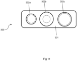
- These control lines 300 may be single control lines, or they may be multiple control lines contained together within a housing or flatpack, such as the flatpack shown in Figure 11 which has a casing 301 surrounding three cables 302a, 302b and 302c.
- the control line clamp assembly 100 has three separate parts, namely a male collar 110, a female collar 120, and a clamping element 130.
- the clamping element 130 is positioned over the control lines 300 and is held in place between the male collar 110 and female collar 120, which together form an attachment mechanism for fixing the control line clamp assembly 100 to the outer surface of the tubing 200.
- the male collar 110 is generally tubular in shape and has a plurality of gripping fingers 114 protruding axially at one end, and a groove or recess 111 for retaining part of the clamping element 130 at the opposing end. Additional views of the male collar 110 are shown in Figures 6a, 6b and 6c .
- the gripping fingers 114 of the male collar 110 are created by providing a plurality of equal length, linear and axially aligned slots. A gripping finger 114 is formed between any two adjacent slots. Each of the gripping fingers 114 extends axially away from a tubular body of the male collar 110.
- the gripping fingers 114 may also be referred to as arms, deformable members or other interchangeable terminology to describe a plurality of elements which extend from a base toward a tip and bend or deflect radially inward from a base to grip the pipe, the elements being separated by slots extending from the tip to the base.
- the plurality of gripping fingers 114 is arranged to deflect or bend radially inward by abutment against the inner surface of the female collar 120, as will be described in more detail below.
- the female collar 120 is also generally tubular in shape and has a recess 121 for retaining part of the clamping element 130 at one end. Additional views of the female collar 120 are shown in Figures 7a, 7b and 7c .
- the inner surface of the female collar 120 has a tapered portion 123 that gives the inner surface a conical shape, i.e. a section of the wall of the female collar 120 is tapered along its longitudinal axis and is therefore shaped like part of the surface of the cone. This tapering means that one end of the female collar 120 is narrower than the other.
- the outer surfaces of the gripping fingers 114 of the male collar 110 abut against this tapered portion 123.
- the gripping fingers 114 also have tapered portions 116, with a narrower outer diameter at the tip of each finger, that is, at the distal end of each finger. In this way, the tapered gripping fingers 114 may more effectively abut the tapered portion 123 of the female sleeve 120.
- the tapering angle of the tapered portions 116 and 123 is preferably substantially the same.
- the male collar 110 and the female collar 120 are positioned axially on the tubing 200 and the male collar 110 is press fitted into the female collar 120.
- the male collar 110 and the female collar 120 are positioned on or around the tubing 200 such that the end of the female collar 120 with the larger inner diameter is forced over the gripping fingers 114 of the male collar 110.
- the tapered portion 123 of female collar 120 causes the gripping fingers 114 to deflect radially inwards to grip the tubing 200.
- the magnitude of deflection increases as the female collar 120 is pressed further over the gripping fingers 114, which reduces the inner circumference defined by the gripping fingers 114. In this way, the gripping fingers 114 provide an inward force against the tubing 200 to fix the control line clamp assembly 110 to the tubing 200.
- one or more ridged grooves/raised ridges/pawls/circumferential annular catches 115 may be provided on the outer surface of the gripping fingers 114.
- a plurality of ridged grooves/raised ridges/pawls/circumferential annular catches 122 is also provided on an inner surface of the female collar 120.
- the ridges 115 on the gripping fingers 114 and the ridges 122 on the female collar 120 together form a ratchet so that after the female collar 120 has been pressed onto a position where the control line clamp assembly 100 is sufficiently gripped to a pipe, the ratchet holds the male collar 110 and female collar 120 in position relative to each other.
- the illustrated male collar 110 has the ridges 115 on the gripping fingers 114, alternatives are envisaged in which the ridges 115 are instead on the body of the male collar 110, i.e. not on the gripping fingers 114.
- the ridges 115 and 122 are each provided with a conical first face, for example with a pitch in the range of 20-35°, and an opposite second face that forms an abutment surface perpendicular to a central axis of the male collar 110 or female collar 120.
- the ridges 115 and 122 are complementary to each other such that as the female collar 120 is pressed axially onto the gripping fingers 114, each ridge 122 on the female collar 120 slides with a conical inward face against the conical outward faces of the circumferential ridges 115 of the gripping fingers 114.
- the gripping fingers 114 are displaced radially inwards until the ridges 122 of female collar 120 engage behind the ridges 115 of the gripping fingers 114.
- ridges 114 and 122 are typically similarly shaped and arranged with regular axial spacing and corresponding pitch angles.
- a similar attachment mechanism is disclosed in WO 2014/011056 A1 , which is hereby incorporated by reference.
- the inner surface of the gripping fingers 114 may comprise a plurality of gripping teeth 117 which grip the tubing 200 when the gripping fingers 114 are deflected radially inwards as the male collar 110 and female collar 120 are pressed together.
- the illustrated gripping teeth 117 are formed of a plurality of circumferential protrusions on the inner part of the gripping fingers 114 at the proximal end or tip of the fingers. Gripping teeth 117 arranged in this way may prevent axial movement of the control line clamp assembly 100 relative to the tubing 200 by creating an edge which transmits force to the tubing 200.
- the gripping teeth 117 may further comprise a series of longitudinal slits (not shown) in the gripping teeth 117 of each gripping finger 114. Such longitudinal slits help to prevent radial movement of the control line clamp assembly 100 by creating additional edges that can exert a radial force on the tubing 200.
- the outer surface of the male collar 110 has several circumferential teeth 112, which in the illustrated embodiment are formed by ridges spanning the entire circumference of the external surface of the male collar 112 without interruption.
- the circumferential teeth 112 are formed by a series of circumferential ridges (for example, with interruptions or slits between sections of teeth) and/or in which the circumferential teeth 112 only span part of the circumference of the male collar 110.
- the circumferential teeth 112 could be replaced by a rough/textured surface that creates a high friction gripping face for abutting against the control lines 300, for example by providing a rough dotted surface.
- the primary purpose of the circumferential teeth 112 is to slightly embed in the outer surface of the control lines 300 or control line housings/casings in order to prevent axial movement of the control lines 300 relative to the control line clamp assembly 100 and tubing 200.
- the teeth additionally help to restrict circumferential movement of the control lines 300 relative to the control line clamp assembly 100 and tubing 200 by providing an edge for exerting an opposing force on the outer surface of the control lines 300.
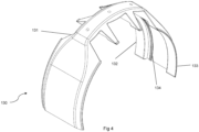
- the male collar 110 also has a series of axial protrusions 113 around its outer circumference, which are shaped to interface with a series of axial protrusions or recesses 134 on the inner surface of the clamping element 130, as visible in Figure 4 .
- the axial protrusions 113 on the male collar 110 are most clearly visible in Figure 6b . Channels/recesses/grooves are formed between adjacent axial protrusions 113 and 134.
- the axial protrusions 113 and 134 are optional components that help to reduce rotational movement of the clamping element 130 relative to the male collar 110 and tubing 200 by increasing the strength of the interaction between the clamping element 130 and the male collar 110.
- the axial protrusions interlock and thereby restrict relative rotational movement between these components (as described in further detail below, the clamping element 130 is held in position radially and axially by the male collar 110 and female collar 120).
- the axial protrusions 113 of the male collar taper in an axial direction away from the gripping fingers 114, i.e. the channel formed between adjacent axial protrusions narrows to a point.
- This optional tapering assists in ensuring that the axial protrusions 113 and 134 align correctly when the clamping element 130 is placed onto the male collar 110.
- the axial protrusions 134 on the inner surface of the clamping element may optionally also be tapered.
- the clamping element 130 may either be free to move rotationally relative to the male collar 110 and tubing 200, or may be held in position relative to the male collar 110 and tubing 200 by friction alone (for example through the friction between the inner surface of the clamping element 130 and the outer surface of the male collar 110, or between any other suitable abutting surfaces).
- the clamping element 130 has a cross section similar to the arc of a circle.
- the cross section of the clamping element 130 is similar in shape to a broken circle, such that the clamping element is generally shaped as part of a tube. Additional views of the clamping element are shown in Figures 8a, 8b and 8c .
- the clamping element 130 is preferably manufactured through a casting process, and may be manufactured of any suitable material, such as steel. The clamping element 130 may alternatively be machined.
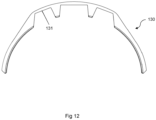
- the arc-shaped cross section of the clamping element 130 may be larger than a semicircle, but alternative embodiments are also envisaged in which the arc-shaped cross section of the clamping element 130 is smaller than a semicircle, such as that shown in Figure 12 .
- Having a cross section larger than a semicircle means that clamping element 130 can be placed against the outer surface of the male collar 110 prior to pressing the male collar 110 and female collar 120 together without the clamping element 130 falling away from the male collar 110.
- this also requires that the clamping element 130 is elastically deformed over the tubing 200 and/or male collar 110 during installation to enable it to fit over the tubing 200 and/or male collar 110.
- the arcuate shape of the clamping element 130 means that it can be placed over the male collar 130 and tubing 200 at any circumferential angle. That is, the clamping element 130 can be positioned anywhere around the circumference of the male collar 110 during installation (as long as the clamping element 130 is aligned with male collar 110 in the axial direction) and does not have to be installed from a particular direction.
- the clamping element 130, male collar 120 and female collar 110 can all be installed at any relative rotational position with respect to each other. This flexibility makes it easier for automated installation of the control line clamp assembly as it removes the need for a specific rotational alignment between the components.
- the clamping element 130 has a first lip or protrusion 132 shaped to be retained in the groove or recess 111 of the male collar 110 and a second lip or protrusion 133 shaped to be retained in the recess 121 of the female collar 120. These lips or protrusions enable the clamping element 130 to be secured in position relative to the tubing 200 by the male collar 110 and female collar 130.
- the lips 132 and 133 are formed as axial flanges protruding from each side of the clamping element 130. While the illustrated lips 132 and 133 are continuous apart from the channels or slots 131 (described below), alternative embodiments are envisaged with discontinuous lips 132 and 133 on one or both sides of the clamping element 130, i.e. multiple shorter lip segments.
- the lips 132 and 133 are shaped to be received in the groove or recess 111 and the recess 121.
- the clamping element 130 is positioned between the male collar 110 and female collar 120 and the two collars are pressed together, the lips 132 and 133 are forced in to the respective groove or recess such that the lips 132 and 133 are at least partly surrounded by the grooves or recesses on the collars.
- each lip 132 and 133 is similar to the radial dimension of the groove or recess into which it is received in order to provide a tight fit that minimises relative radial movement between the clamping element 130 and the collars.
- the axial dimension of the lips 132 and 133 and grooves or recesses should be large enough to ensure that a sufficient length of the lips 132 and 133 is retained within the grooves or recesses to prevent the clamping element 130 coming detached from the collars under high radial or axial forces (for example due to the lips 132 and 133 breaking or deforming or slipping out of the grooves or recesses).
- lips 132 and 133 that are formed by axially protruding flanges
- alternative embodiments are envisaged in which the lips are replaced with other protrusions such as a series of pegs, dowels, catches, arms or fingers that are received in one or more corresponding grooves, recesses or openings on each collar.
- Having multiple axial protrusions on each side of the clamping element 130 that each engage with a corresponding one recess of a similar size i.e. multiple recesses, one for each protrusion restricts relative rotational movement of the clamping element and the collars.
- the protrusions could instead be provided on one or both of the collars, and one or more openings or recesses could be provided on one or both sides of the clamping element 130 for receiving these protrusions.
- the roles of the collars and clamping element could be reversed when it comes to the engagement between the clamping element 130 and the collars.
- the clamping element 130 also has a series of channels or slots 131 for receiving control lines 300.
- the illustrated clamping element 130 has three channels or slots 131, although alternative embodiments are envisaged with more or fewer channels or slots, for example one, two, four, five or six slots.
- the size of each of the channels or slots 131 can be different, and each channel or slot 131 can be sized according to the control line 300 to be received in that slot 131.
- the clamping element 130 is held between the male collar 110 and female collar 120. In the illustrated embodiment, this is achieved by the engagement between the first lip or protrusion 132 of the clamping element 130 and the groove or recess 111 of the male collar 110, and the engagement between the second lip or protrusion 133 of the clamping element 130 and the recess 121 of the female collar 120.
- This engaged or assembled configuration of the control line clamp assembly is shown in Figure 5 .
- the clamping element 130 is positioned abutting the outer surface of the male collar 110, with one or more control lines 300 retained in each slot 131.
- the tapered axial protrusions 113 and 134 help to guide the clamping element 130 into the correct position relative to the male collar 110, i.e. with the respective axial protrusions interlocking.
- the female collar 120 is pressed over the gripping fingers 114 of the male collar 110 as described above.
- the first lip 132 of the clamping element 130 enters the groove or recess 111 of the male collar 110 and the second lip or protrusion 133 of the clamping element 130 enters the recess 121 of the female collar 120.
- both the groove or recess 111 and the recess 121 have tapered sections such that each of the groove or recess 111 and recess 121 is slightly wider at its opening. These tapered sections assist in ensuring the clamping element 130 is pressed tightly against the outer surface of the male collar 110 as the male collar 110 and female collar 120 are pressed together.
- the groove or recess 111 and the recess 121 are preferably sized and shaped to minimise axial and radial movement of the clamping element 130 relative to the collars.
- the sizing of the channels or slots 131 is preferably designed such that the clamping element 130 presses the control lines 300 against the circumferential teeth 112 of the male collar 110, thereby causing the circumferential teeth to embed in the outer surface of the control lines 300 in order to help prevent axial movement of the control lines 300 relative to the control line clamp assembly 100.
- the clamping element 130 must be pressed against the male collar 110 with sufficient force to achieve this.
- attachment in this way means the control line clamp assembly 100 can be attached to a pipe by only pressing the gripping fingers 114 into the female collar 120.
- the control line clamp assembly 100 of the present invention can be mounted to a tubing 200 in an automated manner. No pins, screws or welding are required to attach the control line clamp assembly 100 to the tubing 200.
- control line clamp As the control line clamp according to the present invention is adapted to be installed by a robotic arm or in an automated manner, fewer workers are needed in the red zone on the drill floor. Removing personnel from the red zone during operations on drill floor greatly reduces the overall risk for accidents, and in worst case, deaths. By adding automation in the form of automated installation, the need for personnel can be vastly reduced.
- the attachment of the gripping fingers 114 to the tubing 200 due to the deflection/bending of the gripping fingers 114 allows a very strong gripping force to be applied to the tubing 200.
- the attachment mechanism delivers extremely high holding forces under all operating conditions on a range of different tubing sizes (due to the deflection of the gripping fingers 114 varying depending on how far the male collar 110 and female collar 120 are pressed together).
- control line clamps take a long time to install.
- the press-fit connection of the present invention is quick and easy and dramatically increases the speed of installation and reduces the overall installation time.
- the present invention provides a control line clamp assembly 100 that is compact and easy to handle and can be partially pre-installed onshore.
- the male collar 110 and female collar 120 are positioned around the tubing, for example by sliding them over the end of the collar.
- the gripping fingers 114 of the male collar 110 should be facing toward the end of the female collar 120 with the recess 121.
- Steps 401 and 402 may optionally be performed onshore prior to the tubing 200 being deployed, or they may alternatively be performed when the tubing 200 is being deployed. This may either be performed manually by human workers or by a robotic arm, although if these steps being performed when the tubing 200 is being deployed then it is preferred that these steps are performed in an automated manner.
- the male collar 110 and female collar 120 may optionally be pressed together slightly to lightly attach them to the tubing 200, i.e. they may be pressed together such that the gripping fingers are slightly deformed towards the outer surface of the tubing 200 just enough to grip the outer surface of the tubing 200 when no additional load is exerted on the collars.
- the collars should not be pressed fully together, i.e. they should only be pressed such that the clamping element 130 can still be positioned between the recess or groove 111 of the male collar 110 and the recess 121 of the female collar.
- This step is particularly advantageous when the collars are installed onshore, as it will ensure the collars do not move significantly relative to the tubing 200 during transit. Again, this step may either be performed manually by human workers or by robotic or automated installation, but it is preferred that it be performed in an automated manner if this step is being performed during deployment of the tubing 200.
- one or more control lines 300 are positioned alongside the tubing 200, and the clamping element 130 is then positioned over the control lines 300 between the male collar 110 and the female collar in step 404.
- these steps will generally be performed during deployment of the tubing 300, it is preferred for them to be performed by automation, but they may alternatively be performed by human workers.
- the positioning of the control lines 300 alongside the tubing may be performed by a robotic control line manipulator such as that described in US 2013/0186640 A1
- the clamping element 130 may be positioned by a robotic clamp handling device such as that described in US 2008/0023192 A1 .
- step 404 will involve elastically deforming the clamping element 130 in order to allow it to fit over the male collar 110 and tubing 200. This will generally be performed by a specialist tool capable of deforming the clamping element 130 as required.
- the clamping element 130 can be installed from any angle around the circumference of the male collar 110 due to the arcuate shape of the clamping element 130.
- these protrusions and recesses will help to ensure the clamping element 130 is correctly positioned with respect to the male collar 110.
- the clamping element 130 presses the control lines 300 into the circumferential teeth 112, thereby causing the circumferential teeth to bite into the outer surface of each control line 300 in order to restrict axial movement of the control lines 300 relative to the male collar 110.
- the male collar 110 and female collar 120 are moved relatively towards each other in step 405.
- the male collar 110 is held fixed and the female collar 120 pressed over the male collar 110.
- the female collar may 120 may alternatively be held fixed and the male collar 110 pressed into the female, or both collars may be moved simultaneously towards each other.
- any number of known tools for press fitting tubular parts that are arranged around the pipe may be used.
- the press fitting tool as shown in Figures 2 and 3 of US 3,040,405 which is hereby incorporated by reference, may be used.
- Such a press fitting tool may be used in combination with existing robotic clamp handling device such as that described in US 2008/0023192 A1 .
- the arm will position the press fitting tool such that a first pressing surface of the tool abuts the end of the male collar 110 that is furthest from the female collar and a second pressing surface of the tool abuts the end of the female collar 120 that is furthest from the male collar.
- the device will then actuate the tool to apply an axial compression force between the first and second pressing surfaces to thereby press the two collars relatively towards each other and force the male collar 110 and female collar 120 together. This could be performed by moving both pressing surfaces of the tool towards each other, or alternatively by keeping one pressing surface fixed and moving the other. Once the collars are pressed together, the control line clamp assembly 100 will be attached to the tubing.
- control line clamp assembly is suitable for industrial applications, in particular for use in the subsea oil and gas industry.
- the elements of the control line clamp assembly may be made of any material known for such applications, such as steel.
- the dimensions of the components described may be adapted as required to the control lines, pipes and other devices used in these industries.
- control line clamp assembly shows the clamping element 130 abutting the outer surface of the male collar 110, the roles of the male collar 110 and female collar 120 could be swapped such that the clamping element abuts the outer surface of the female collar 120.
- the circumferential teeth 112 may be on the outer surface of the female collar, as may the optional axial protrusions 113.
- alternative embodiments of the assembly may comprise a clamping element with gripping fingers 114, where the assembly is installed by positing the clamping element over the control lines 300 and pressing the gripping fingers 114 of the clamping element into the female collar 120.
- a single collar may be attached to the tubing 200 (for example by welding or using set screws) and the clamping element may be positioned over one or more control lines 300 and attached to the outer surface of the single collar using clips or friction or similar.
- the illustrated embodiment has two lips on the clamping element 130 that are received in corresponding grooves and/or recesses on the male collar 110 and female collar 120
- alternative embodiments are envisaged in which the clamping element 130 has a single lip and only one of the male collar 110 and female collar 120 have a groove or recess.
- the end of the clamping element 130 without a lip will preferably abut against an abutment portion of either the male collar 110 or female collar 120 when the male collar 110 and female collar 120 are pressed together.
- the lip and groove/recess engagement could also be replaced with other engagement interfaces, for example with other forms of interlocking protrusions and openings.
- the male and female collars could be positioned either side of the clamping element and pressed together to engage with the clamping element (for example through the lip and recess arrangement described above), but rather than having deformable fingers that grip the pipe and a ratchet that holds the collars together, the collars could be attached to the pipe by tightening one or more set screws or by welding one or both of them to a pipe. Welding or tightening set screws could either be performed manually or by automation.
Abstract
A method for attaching a control line clamp to a pipe for subsea oil and gas, the control line clamp comprising a clamping element for retaining one or more control lines alongside a pipe; a first collar; and a second collar, wherein the clamping element is arranged to be attached to the pipe by positioning the first and second collars around the pipe on opposing sides of the clamping element and moving the first and second collars relatively towards each other in an axial direction. Within the method the control line clamp is partially installed onshore.
Description
- Control lines are used to control, provide power to, and communicate with downhole equipment during hydrocarbon extraction. Control lines may be electrical cables, fibre optic lines or hydraulic lines for example, and they can be connected to a variety of downhole equipment such as hydraulic pumps, valves and sensors.
- Control lines are commonly arranged around the outside of a production tubing and are run into a wellbore in parallel with the tubing. Several control lines may run alongside each other and perform different tasks, and multiple control lines can be spliced within a single housing or flatpack and separated out as needed.
- It is known to use control line clamps to attach control lines to the outer surface of a downhole pipe, such as a production tubing. This is generally performed manually by workers on the rig floor when the production tubing is lowered into the wellbore. This area of the rig floor is known as the red zone and is a dangerous place for workers due to the close proximity to heaving drilling equipment.
- In addition, existing control line clamps are heavy for workers to manoeuvre and often require relatively intricate tasks to be performed during installation, such as tightening screws. Installation of these clamps is therefore labour intensive, making it both expensive and time consuming.
- According to a first aspect of the invention, there is provided a control line clamp assembly comprising a clamping element for retaining one or more control lines alongside a pipe; a first collar; and a second collar, wherein the clamping element is arranged to be attached to the pipe by positioning the first and second collars around the pipe on opposing sides of the clamping element and moving the first and second collars relatively towards each other in an axial direction.
- The axial direction is the direction parallel to the axis of the pipe.
- Advantageously, the components of the control line clamp assembly are shaped to be held and manipulated by automation, for example a robot, so that the assembly can be installed by in an automated manner, i.e. without human intervention. In an example implementation, the automation grips the clamping element and positions it against the outer surface of the first collar at any circumferential angle and then presses the first collar and second collar together to attach the control line clamp to the pipe.
- Unlike conventionally mounted control line clamps, which are often screwed or welded onto a tubing, the control line clamp of the present invention can be attached to a pipe simply by positioning the first and second collars around the pipe on either side of the clamping element and pressing them together, thereby facilitating installation of the control line clamp assembly by a robot. No pins, screws or welding are required to attach the control line clamp assembly to the tubing.
- As the control line clamp assembly is adapted to be installed by in an automated manner, fewer workers are needed in the red zone on the drill floor. Removing personnel from the red zone during operations on the drill floor greatly reduces the overall risk for accidents, and in worst case, deaths. By adding automation in the form of robotic installation, the need for personnel can be vastly reduced.
- In addition, automated installation is both quicker and cheaper than manual installation and has the potential to be more reliable and repeatable.
- Preferably, the first collar comprises an engagement region arranged to engage with a first engagement region on the clamping element. Additionally or alternatively, the second collar may also comprise an engagement region arranged to engage with a second engagement region on the clamping element.
- In use, at least part of the engagement region on each collar surrounds at least part of the corresponding engagement region on the clamping element. This engagement between the engagement region of the collar and the engagement region of the clamping element restricts axial and radial movement of the clamping element relative to the collars through abutment between the respective engagement regions. In other words, when the control line clamp is installed, the engagement regions couple the clamping element to each collar so that the clamping element does not separate from the collars.
- In some embodiments, the engagement region on the first and/or second collar may comprise one or more recesses or slots, and the first and/or second engagement region on the clamping element may comprise one or more axial lips or protrusions.
- Alternatively, the engagement region on the first and/or second collar may comprise one or more axial lips on protrusions and the first and/or second engagement region on the clamping element may comprise one or more recesses or slots.
- The axial lips or protrusions are arranged to be received in the recesses or slots such that that the recesses or slots at least partly surround the axial lips or protrusions when the first and second collars are pressed together. In use, the inner surfaces of the recesses or slots provide a surface against which the lips or protrusions abut so as to restrict or prevent relative axial and radial movement between the clamping element and collars.
- Preferably, the first and/or second collars are adapted to be fixed to the pipe and/or other collar, thereby preventing the collars moving axially along the pipe or rotating about the pipe.
- As the clamping element is fixed relative to the collars, fixing one or both of the collars to the pipe in turn prevents the clamping element moving axially along the pipe.
- In some embodiments, the first collar is a male collar and the second collar is a female sleeve, wherein the female sleeve is arranged to receive at least part of the male collar. Alternatively, the first collar may be a female sleeve and the second collar may be a male collar, wherein the female sleeve is arranged to receive at least part of the male collar.
- In embodiments where one collar is a male collar and the other collar is a female collar, the male collar preferably comprises a plurality of fingers and the female sleeve is preferably arranged to receive the plurality of fingers, wherein when the male collar and female sleeve are pressed together each of the plurality of fingers is deflected inwards to grip the pipe. This allows the control line clamp assembly to be attached to the pipe simply by pressing the male collar and female sleeve together, thereby causing the plurality of fingers to defect towards the pipe. The deflection of the fingers against the pipe holds the male collar against the outer surface of the pipe.
- Preferably, when pressed together, the male collar and female sleeve are held together by a ratchet. This ratchet mechanism prevents the male collar and female sleeve moving axially away from each other, i.e. the female collar is fixed to the male collar by more than friction alone. As the fingers of the male collar attach the male collar to the pipe, the attachment between the male and female collars in turn fixes the female collar to the pipe. Because the clamping element is retained by the male and female collars being pressed together, the ratchet also ensures that the clamping element remains fixed in position relative to the pipe.
- In some embodiments, an inner surface of the clamping element may be arranged to abut a circumferential outer surface of the first collar.
- The circumferential outer surface of the first collar may comprise one or more protrusions arranged to engage or interlock with a corresponding one or more recesses on the inner surface of the clamping element.
- Alternatively, the circumferential outer surface of the first collar may comprise one or more recesses arranged to engage with a corresponding one or more protrusions on the inner surface of the clamping element.
- These protrusions and recesses help to prevent rotational movement of the clamping element relative to the first and/or second collars by providing one or more surfaces that oppose relative rotational movement between the collars and the clamping element, that is, one or more abutting surfaces that are perpendicular to the circumference of the pipe.
- In addition, the one or more protrusions may be tapered in an axial direction such that the one or more protrusions on the first collar are thinner towards the end of the first collar that faces towards the second collar when installed, and thicker towards the end of the first collar that faces away from the second collar in use.
- Additionally, the corresponding one or more recesses may be tapered in a corresponding axial direction such that the tapered recesses cooperate with the tapered protrusions. This tapering of the protrusions and recesses helps to ensure that the protrusions and recesses align correctly during installation of the control line clamp assembly. The tapering guides or channels the protrusions into the recesses as the protrusions and recesses engage with each other.
- In some embodiments, the circumferential outer surface of the first collar may comprise one or more circumferential teeth arranged to engage with an outer surface of a control line or control line housing. The circumferential teeth embed in the outer surface of a control line, control line housing or flatpack, thereby reducing the risk of the control lines moving axially relative to the control line clamp assembly.
- According to a second aspect of the invention, there is provided a control line clamp assembly comprising clamping element for retaining one or more control lines alongside a pipe; and a collar, wherein the clamping element is adapted to engage with the collar and wherein the clamping element and collar are together adapted to attach to the pipe.
- The components of the control line clamp assembly are shaped to be held and manipulated by a robot so that the assembly can be installed in an automated manner. In an example implementation, the automation grips the clamping element and positions it against the outer surface of the first collar at any circumferential angle and then presses the clamping element and collar together to attach the control line clamp to the pipe.
- Unlike conventionally mounted control line clamps, which are often screwed or welded onto a tubing, the control line clamp of the present invention can be attached to a pipe simply by positioning the first and second collars around the pipe on either side of the clamping element and pressing them together, thereby facilitating installation of the control line clamp assembly by automation. No pins, screws or welding are required to attach the control line clamp assembly to the tubing.
- As the control line clamp assembly is adapted to be installed by automation, fewer workers are needed in the red zone on the drill floor. Removing personnel from the red zone during operations on drill floor greatly reduces the overall risk for accidents, and in worst case, deaths. By adding automation in the form of automated installation, the need for personnel can be vastly reduced.
- In addition, automated installation is both quicker and cheaper than manual installation and has the potential to be more reliable and repeatable.
- In some embodiments according to the second aspect, the clamping element is arranged to be attached to the pipe by positioning the collar around the pipe and positioning the clamping element against an outer surface of the pipe and moving the collar and clamping element relatively towards each other in an axial direction.
- Preferably, the collar comprises an engagement region arranged to engage with an engagement region on the clamping element.
- In use, at least part of the engagement region on the collar surrounds at least part of the engagement region on the clamping element. This engagement between the engagement region of the collar and the engagement region of the clamping element restricts axial and radial movement of the clamping element relative to the collars through abutment between the respective engagement regions. In other words, when the control line clamp is installed, the engagement regions couple the collar and clamping element so that they do not separate.
- In some embodiments, the engagement region on the collar may comprise one or more recesses or slots and the engagement region on the clamping element may comprise one or more axial lips or protrusions.
- Alternatively, the engagement region on the clamping may comprise one or more axial lips on protrusions and the engagement region on the clamping element may comprise one or more recesses or slots.
- The axial lips or protrusions are arranged to be received in the recesses or slots such that that the recesses or slots at least partly surround the axial lips or protrusions when the collar and clamping element are pressed together. In use, the inner surfaces of the recesses or slots provide a surface against which the lips or protrusions abut so as to restrict or prevent relative axial and radial movement between the clamping element and collar..
- In some embodiments of the second aspect, the collar is a female sleeve, wherein the female sleeve is arranged to receive at least part of the clamping element.
- In embodiments where the collar is a female sleeve, the clamping element preferably comprises a plurality of fingers and the female sleeve is arranged to receive the plurality of fingers, wherein when the clamping element and female sleeve are pressed together each of the plurality of fingers is deflected inwards to grip the pipe. This allows the control line clamp assembly to be attached to the pipe simply by pressing the male collar and female sleeve together, thereby causing the plurality of fingers to defect towards the pipe. The deflection of the fingers against the pipe holds the clamping element against the outer surface of the pipe.
- Preferably, when pressed together, the clamping element and female sleeve are held together by a ratchet. This ratchet mechanism prevents the clamping element and female sleeve moving axially away from each other, i.e. the female collar is fixed to the clamping element by more than friction alone.
- In embodiments of the both the first and second aspect, the inner surface of the clamping element may comprise one or more slots arranged to receive one or more control lines or control line housings. These slots allow control lines to be retained alongside the pipe by the control line clamp assembly.
- Preferably, the clamping element has an arc-shaped cross section. This allows the clamping element to be positioned over the pipe as the pipe is run into the wellbore. The collars can be placed around the pipe prior to completion, and the clamping element can be positioned during completion. The arcuate shape of the clamping element means that the control lines do not have to be threaded through the clamping element when being deployed, thereby simplifying installation.
- Optionally, the arc-shaped cross section may be larger than a semicircle. This increases the holding force of the clamping element around the pipe and increase the contact surface area between the clamping element and the first and/or collar.
- Alternatively, the arc-shaped cross section may be smaller than a semicircle. This means the clamping element does not need to be elastically deformed as it is positioned over the pipe.
- The arc-shaped cross section may alternatively be a semicircle.
- According to a third aspect of the invention, there is provided a method for attaching a control line clamp according to any preceding claim to a pipe, comprising: positioning the first collar around the pipe; positioning the second collar around the pipe; positioning one or more control lines alongside the pipe; positioning the clamping element over the control lines with at least part of the clamping element between at least part of the first collar and at least part of the second collar; and moving the first and second collars relatively towards each other in an axial direction to thereby attach the clamping element to the pipe.
- This method can be performed by in an automated manner. The automation manipulates the collars and clamping elements into the correct positions and presses the collars together. No pins, screws or welding are required to attach the control line clamp assembly to the tubing.
- As the control line clamp assembly is adapted to be installed in an automated matter, fewer workers are needed in the red zone on the drill floor. Removing personnel from the red zone during operations on drill floor greatly reduces the overall risk for accidents, and in worst case, deaths. By adding automation in the form of automation installation, the need for personnel can be vastly reduced.
- Preferably the method further comprises pressing the first and second collars loosely together prior to positioning the clamping element over the control lines between the first and second collars, wherein moving the first and second collars relatively towards each other in the axial direction comprises further pressing the first and second collars together.
- This allows the collars to be loosely attached to the pipe in a pre-configured position, thereby removing the need to hold them in place around the pipe when installing the clamping element.
- Even more preferably, the method further comprises lightly pressing the first collar and second collar together prior to positioning the one or more control lines alongside the pipe.
- This allows the collars to be loosely attached to the pipe in a pre-configured position, thereby removing the need to hold them in place around the pipe when installing the clamping element. This can optionally be performed on-shore prior to completion.
- Examples of the present invention will now be described in detail with reference to the accompanying drawings, in which:
-
Figure 1 shows a control line clamp assembly attached to a tubing; -
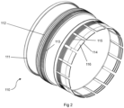
Figure 2 shows a male collar of the control line clamp assembly; -
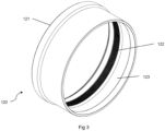
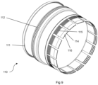
Figure 3 shows a female collar of the control line clamp assembly; -
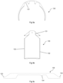
Figure 4 shows a clamping element of the control line clamp assembly; -
Figure 5 shows the control line clamp assembly in an assembled configuration; -
Figures 6a, 6b and 6c show end-on, side-on and cross-sectional views of the male collar respectively; -
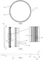
Figures 7a, 7b and 7c show end-on, side-on and cross-sectional views of the female collar respectively; -
Figures 8a, 8B and 8c show end-on, side-on and cross-sectional views of the clamping element respectively; -
Figure 9 shows an alternative embodiment of a male collar; -
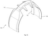
Figure 10 shows an alternative embodiment of a clamping element; -
Figure 11 shows a cross section of a flatpack; -
Figure 12 shows a side view of another alternative embodiment of a clamping element; and -
Figure 13 is a block diagram illustrating an exemplary installation method for installing the control line clamp assembly on a tubing. - The present invention provides an improved control line clamp for attachment to the outer surface of a pipe for securing control lines alongside a tubing or other pipe. Although the control line clamp is described in relation to a device for securing or clamping control lines to the outside of a production tubing, it could also be used for clamping control lines or similar to a casing string or any other tubular used in hydrocarbon extraction.
- The words tubular, casing, pipe, production tubing and tubing may be used interchangeably through the present description to refer to a production tubing or similar which is run into a wellbore within a casing or casing string or similar.
-
Figure 1 shows a controlline clamp assembly 100 attached to atubing 200. The controlline clamp assembly 100 is shown retainingseveral control lines 300 alongside thetubing 200. Thesecontrol lines 300 may be single control lines, or they may be multiple control lines contained together within a housing or flatpack, such as the flatpack shown inFigure 11 which has acasing 301 surrounding threecables - As shown in
Figures 2 ,3 ,4 and5 , the controlline clamp assembly 100 has three separate parts, namely amale collar 110, afemale collar 120, and aclamping element 130. In use, the clampingelement 130 is positioned over thecontrol lines 300 and is held in place between themale collar 110 andfemale collar 120, which together form an attachment mechanism for fixing the controlline clamp assembly 100 to the outer surface of thetubing 200. - Referring now to
Figure 2 , themale collar 110 is generally tubular in shape and has a plurality ofgripping fingers 114 protruding axially at one end, and a groove orrecess 111 for retaining part of theclamping element 130 at the opposing end. Additional views of themale collar 110 are shown inFigures 6a, 6b and 6c . - The gripping
fingers 114 of themale collar 110 are created by providing a plurality of equal length, linear and axially aligned slots. Agripping finger 114 is formed between any two adjacent slots. Each of the grippingfingers 114 extends axially away from a tubular body of themale collar 110. - The gripping
fingers 114 may also be referred to as arms, deformable members or other interchangeable terminology to describe a plurality of elements which extend from a base toward a tip and bend or deflect radially inward from a base to grip the pipe, the elements being separated by slots extending from the tip to the base. - To fix or mount the control
line clamp assembly 100 to thetubing 200, the plurality ofgripping fingers 114 is arranged to deflect or bend radially inward by abutment against the inner surface of thefemale collar 120, as will be described in more detail below. - Referring now to
Figure 3 , thefemale collar 120 is also generally tubular in shape and has arecess 121 for retaining part of theclamping element 130 at one end. Additional views of thefemale collar 120 are shown inFigures 7a, 7b and 7c . - As best seen in
Figure 7c , the inner surface of thefemale collar 120 has a taperedportion 123 that gives the inner surface a conical shape, i.e. a section of the wall of thefemale collar 120 is tapered along its longitudinal axis and is therefore shaped like part of the surface of the cone. This tapering means that one end of thefemale collar 120 is narrower than the other. - In use, the outer surfaces of the gripping
fingers 114 of themale collar 110 abut against this taperedportion 123. As best seen inFigure 6c , the grippingfingers 114 also have taperedportions 116, with a narrower outer diameter at the tip of each finger, that is, at the distal end of each finger. In this way, the taperedgripping fingers 114 may more effectively abut the taperedportion 123 of thefemale sleeve 120. The tapering angle of the taperedportions - To attach the control
line clamp assembly 100 to atubing 200, themale collar 110 and thefemale collar 120 are positioned axially on thetubing 200 and themale collar 110 is press fitted into thefemale collar 120. Themale collar 110 and thefemale collar 120 are positioned on or around thetubing 200 such that the end of thefemale collar 120 with the larger inner diameter is forced over the grippingfingers 114 of themale collar 110. As thefemale collar 120 is pressed over the grippingfingers 114, the taperedportion 123 offemale collar 120 causes the grippingfingers 114 to deflect radially inwards to grip thetubing 200. - The magnitude of deflection increases as the
female collar 120 is pressed further over the grippingfingers 114, which reduces the inner circumference defined by the grippingfingers 114. In this way, the grippingfingers 114 provide an inward force against thetubing 200 to fix the controlline clamp assembly 110 to thetubing 200. - Referring now to
Figures 6c and7c , one or more ridged grooves/raised ridges/pawls/circumferentialannular catches 115 may be provided on the outer surface of the grippingfingers 114. A plurality of ridged grooves/raised ridges/pawls/circumferentialannular catches 122 is also provided on an inner surface of thefemale collar 120. Theridges 115 on the grippingfingers 114 and theridges 122 on thefemale collar 120 together form a ratchet so that after thefemale collar 120 has been pressed onto a position where the controlline clamp assembly 100 is sufficiently gripped to a pipe, the ratchet holds themale collar 110 andfemale collar 120 in position relative to each other. - Although the illustrated
male collar 110 has theridges 115 on the grippingfingers 114, alternatives are envisaged in which theridges 115 are instead on the body of themale collar 110, i.e. not on the grippingfingers 114. - The
ridges male collar 110 orfemale collar 120. Theridges female collar 120 is pressed axially onto the grippingfingers 114, eachridge 122 on thefemale collar 120 slides with a conical inward face against the conical outward faces of thecircumferential ridges 115 of the grippingfingers 114. The grippingfingers 114 are displaced radially inwards until theridges 122 offemale collar 120 engage behind theridges 115 of the grippingfingers 114. Once engaged, abutment between the respective perpendicular second faces of theridges male collar 110 andfemale collar 120 being separated by an axial force, effectively locking the grippingarms 114, and therefore themale collar 110, within thefemale collar 120. Theridges WO 2014/011056 A1 , which is hereby incorporated by reference. - As seen in
Figure 7c , the inner surface of the grippingfingers 114 may comprise a plurality ofgripping teeth 117 which grip thetubing 200 when the grippingfingers 114 are deflected radially inwards as themale collar 110 andfemale collar 120 are pressed together. - The illustrated
gripping teeth 117 are formed of a plurality of circumferential protrusions on the inner part of the grippingfingers 114 at the proximal end or tip of the fingers. Grippingteeth 117 arranged in this way may prevent axial movement of the controlline clamp assembly 100 relative to thetubing 200 by creating an edge which transmits force to thetubing 200. - The gripping
teeth 117 may further comprise a series of longitudinal slits (not shown) in the grippingteeth 117 of eachgripping finger 114. Such longitudinal slits help to prevent radial movement of the controlline clamp assembly 100 by creating additional edges that can exert a radial force on thetubing 200. - Referring again to
Figure 2 , the outer surface of themale collar 110 has severalcircumferential teeth 112, which in the illustrated embodiment are formed by ridges spanning the entire circumference of the external surface of themale collar 112 without interruption. Although this is a preferred embodiment, alternative embodiments are envisaged in which thecircumferential teeth 112 are formed by a series of circumferential ridges (for example, with interruptions or slits between sections of teeth) and/or in which thecircumferential teeth 112 only span part of the circumference of themale collar 110. Alternatively, thecircumferential teeth 112 could be replaced by a rough/textured surface that creates a high friction gripping face for abutting against thecontrol lines 300, for example by providing a rough dotted surface. - The primary purpose of the
circumferential teeth 112 is to slightly embed in the outer surface of thecontrol lines 300 or control line housings/casings in order to prevent axial movement of thecontrol lines 300 relative to the controlline clamp assembly 100 andtubing 200. - For embodiments in which the
circumferential teeth 112 are formed by a series of interrupted ridges, the teeth additionally help to restrict circumferential movement of thecontrol lines 300 relative to the controlline clamp assembly 100 andtubing 200 by providing an edge for exerting an opposing force on the outer surface of the control lines 300. - In addition to the
circumferential teeth 112, themale collar 110 also has a series ofaxial protrusions 113 around its outer circumference, which are shaped to interface with a series of axial protrusions or recesses 134 on the inner surface of theclamping element 130, as visible inFigure 4 . Theaxial protrusions 113 on themale collar 110 are most clearly visible inFigure 6b . Channels/recesses/grooves are formed between adjacentaxial protrusions - The
axial protrusions clamping element 130 relative to themale collar 110 andtubing 200 by increasing the strength of the interaction between the clampingelement 130 and themale collar 110. When theclamping element 130 is placed against themale collar 110, the axial protrusions interlock and thereby restrict relative rotational movement between these components (as described in further detail below, the clampingelement 130 is held in position radially and axially by themale collar 110 and female collar 120). - As can be seen in
Figure 6b , theaxial protrusions 113 of the male collar taper in an axial direction away from the grippingfingers 114, i.e. the channel formed between adjacent axial protrusions narrows to a point. This optional tapering assists in ensuring that theaxial protrusions clamping element 130 is placed onto themale collar 110. Theaxial protrusions 134 on the inner surface of the clamping element may optionally also be tapered. - Alternative embodiments of the
male collar 110 and clampingelement 130 are shown without axial protrusions inFigures 9 and10 . With these alternative embodiments, the clampingelement 130 may either be free to move rotationally relative to themale collar 110 andtubing 200, or may be held in position relative to themale collar 110 andtubing 200 by friction alone (for example through the friction between the inner surface of theclamping element 130 and the outer surface of themale collar 110, or between any other suitable abutting surfaces). - Referring now to
Figure 4 , the clampingelement 130 has a cross section similar to the arc of a circle. In other words, the cross section of theclamping element 130 is similar in shape to a broken circle, such that the clamping element is generally shaped as part of a tube. Additional views of the clamping element are shown inFigures 8a, 8b and 8c . The clampingelement 130 is preferably manufactured through a casting process, and may be manufactured of any suitable material, such as steel. The clampingelement 130 may alternatively be machined. - As visible in
Figure 8a , the arc-shaped cross section of theclamping element 130 may be larger than a semicircle, but alternative embodiments are also envisaged in which the arc-shaped cross section of theclamping element 130 is smaller than a semicircle, such as that shown inFigure 12 . Having a cross section larger than a semicircle means that clampingelement 130 can be placed against the outer surface of themale collar 110 prior to pressing themale collar 110 andfemale collar 120 together without the clampingelement 130 falling away from themale collar 110. However, this also requires that the clampingelement 130 is elastically deformed over thetubing 200 and/ormale collar 110 during installation to enable it to fit over thetubing 200 and/ormale collar 110. - The arcuate shape of the
clamping element 130 means that it can be placed over themale collar 130 andtubing 200 at any circumferential angle. That is, the clampingelement 130 can be positioned anywhere around the circumference of themale collar 110 during installation (as long as the clampingelement 130 is aligned withmale collar 110 in the axial direction) and does not have to be installed from a particular direction. The clampingelement 130,male collar 120 andfemale collar 110 can all be installed at any relative rotational position with respect to each other. This flexibility makes it easier for automated installation of the control line clamp assembly as it removes the need for a specific rotational alignment between the components. - As best seen in
Figure 8c , the clampingelement 130 has a first lip orprotrusion 132 shaped to be retained in the groove orrecess 111 of themale collar 110 and a second lip orprotrusion 133 shaped to be retained in therecess 121 of thefemale collar 120. These lips or protrusions enable theclamping element 130 to be secured in position relative to thetubing 200 by themale collar 110 andfemale collar 130. - As shown in
Figures 4 ,8b and 8c , thelips clamping element 130. While the illustratedlips discontinuous lips clamping element 130, i.e. multiple shorter lip segments. - As mentioned above, the
lips recess 111 and therecess 121. When theclamping element 130 is positioned between themale collar 110 andfemale collar 120 and the two collars are pressed together, thelips lips - Ideally the radial dimension of each
lip element 130 and the collars. - In addition, the axial dimension of the
lips lips clamping element 130 coming detached from the collars under high radial or axial forces (for example due to thelips - While the illustrated embodiment has
lips clamping element 130 that each engage with a corresponding one recess of a similar size (i.e. multiple recesses, one for each protrusion) restricts relative rotational movement of the clamping element and the collars. - Furthermore, the protrusions could instead be provided on one or both of the collars, and one or more openings or recesses could be provided on one or both sides of the
clamping element 130 for receiving these protrusions. In other words, the roles of the collars and clamping element could be reversed when it comes to the engagement between the clampingelement 130 and the collars. - The clamping
element 130 also has a series of channels orslots 131 for receivingcontrol lines 300. The illustratedclamping element 130 has three channels orslots 131, although alternative embodiments are envisaged with more or fewer channels or slots, for example one, two, four, five or six slots. The size of each of the channels orslots 131 can be different, and each channel or slot 131 can be sized according to thecontrol line 300 to be received in thatslot 131. - As mentioned above, in use, the clamping
element 130 is held between themale collar 110 andfemale collar 120. In the illustrated embodiment, this is achieved by the engagement between the first lip orprotrusion 132 of theclamping element 130 and the groove orrecess 111 of themale collar 110, and the engagement between the second lip orprotrusion 133 of theclamping element 130 and therecess 121 of thefemale collar 120. This engaged or assembled configuration of the control line clamp assembly is shown inFigure 5 . - In use, the clamping
element 130 is positioned abutting the outer surface of themale collar 110, with one ormore control lines 300 retained in eachslot 131. For embodiments with taperedaxial protrusions axial protrusions clamping element 130 into the correct position relative to themale collar 110, i.e. with the respective axial protrusions interlocking. - Once the clamping
element 130 is in position against themale collar 110, thefemale collar 120 is pressed over the grippingfingers 114 of themale collar 110 as described above. As themale collar 110 andfemale collar 120 are pressed relatively towards each other, thefirst lip 132 of theclamping element 130 enters the groove orrecess 111 of themale collar 110 and the second lip orprotrusion 133 of theclamping element 130 enters therecess 121 of thefemale collar 120. Once thelips clamping element 130 relative to the collars is restricted, i.e. the clampingelement 130 cannot move along thetubing 200 or away from thetubing 200 relative to the collars. - As can be seen in
Figures 6c and7c , both the groove orrecess 111 and therecess 121 have tapered sections such that each of the groove orrecess 111 andrecess 121 is slightly wider at its opening. These tapered sections assist in ensuring theclamping element 130 is pressed tightly against the outer surface of themale collar 110 as themale collar 110 andfemale collar 120 are pressed together. The groove orrecess 111 and therecess 121 are preferably sized and shaped to minimise axial and radial movement of theclamping element 130 relative to the collars. - The sizing of the channels or
slots 131 is preferably designed such that the clampingelement 130 presses thecontrol lines 300 against thecircumferential teeth 112 of themale collar 110, thereby causing the circumferential teeth to embed in the outer surface of thecontrol lines 300 in order to help prevent axial movement of thecontrol lines 300 relative to the controlline clamp assembly 100. The clampingelement 130 must be pressed against themale collar 110 with sufficient force to achieve this. This could either be achieved by pressing theclamping element 130 firmly against themale collar 110 prior to pressing themale collar 110 andfemale collar 120 together, or it could be occur as a result of the tapering of the grooves or recesses 111 and 121 of the collars pressing clampingelement 110 towards the outer surface of themale collar 110 as themale collar 110 andfemale collar 120 are pressed together. - Advantageously, attachment in this way means the control
line clamp assembly 100 can be attached to a pipe by only pressing thegripping fingers 114 into thefemale collar 120. Unlike conventionally mounted control line clamps, which are often screwed or welded onto a tubing, the controlline clamp assembly 100 of the present invention can be mounted to atubing 200 in an automated manner. No pins, screws or welding are required to attach the controlline clamp assembly 100 to thetubing 200. - As the control line clamp according to the present invention is adapted to be installed by a robotic arm or in an automated manner, fewer workers are needed in the red zone on the drill floor. Removing personnel from the red zone during operations on drill floor greatly reduces the overall risk for accidents, and in worst case, deaths. By adding automation in the form of automated installation, the need for personnel can be vastly reduced.
- In addition to the advantages that result from facilitating automated installation, the attachment of the gripping
fingers 114 to thetubing 200 due to the deflection/bending of the grippingfingers 114 allows a very strong gripping force to be applied to thetubing 200. The attachment mechanism delivers extremely high holding forces under all operating conditions on a range of different tubing sizes (due to the deflection of the grippingfingers 114 varying depending on how far themale collar 110 andfemale collar 120 are pressed together). - Additionally, conventional control line clamps take a long time to install. The press-fit connection of the present invention is quick and easy and dramatically increases the speed of installation and reduces the overall installation time. The present invention provides a control
line clamp assembly 100 that is compact and easy to handle and can be partially pre-installed onshore. - An exemplary method for attaching the control
line clamp assembly 100 to thetubing 200 will now be described with reference toFigure 13 . - In
steps male collar 110 andfemale collar 120 are positioned around the tubing, for example by sliding them over the end of the collar. The grippingfingers 114 of themale collar 110 should be facing toward the end of thefemale collar 120 with therecess 121. -
Steps tubing 200 being deployed, or they may alternatively be performed when thetubing 200 is being deployed. This may either be performed manually by human workers or by a robotic arm, although if these steps being performed when thetubing 200 is being deployed then it is preferred that these steps are performed in an automated manner. - At this stage, the
male collar 110 andfemale collar 120 may optionally be pressed together slightly to lightly attach them to thetubing 200, i.e. they may be pressed together such that the gripping fingers are slightly deformed towards the outer surface of thetubing 200 just enough to grip the outer surface of thetubing 200 when no additional load is exerted on the collars. The collars should not be pressed fully together, i.e. they should only be pressed such that the clampingelement 130 can still be positioned between the recess or groove 111 of themale collar 110 and therecess 121 of the female collar. - This step is particularly advantageous when the collars are installed onshore, as it will ensure the collars do not move significantly relative to the
tubing 200 during transit. Again, this step may either be performed manually by human workers or by robotic or automated installation, but it is preferred that it be performed in an automated manner if this step is being performed during deployment of thetubing 200. - At
step 403, one ormore control lines 300 are positioned alongside thetubing 200, and theclamping element 130 is then positioned over thecontrol lines 300 between themale collar 110 and the female collar instep 404. As these steps will generally be performed during deployment of thetubing 300, it is preferred for them to be performed by automation, but they may alternatively be performed by human workers. The positioning of thecontrol lines 300 alongside the tubing may be performed by a robotic control line manipulator such as that described inUS 2013/0186640 A1 , and theclamping element 130 may be positioned by a robotic clamp handling device such as that described inUS 2008/0023192 A1 . - When the arc-shaped cross section of the
clamping element 130 is larger than a semicircle,step 404 will involve elastically deforming theclamping element 130 in order to allow it to fit over themale collar 110 andtubing 200. This will generally be performed by a specialist tool capable of deforming theclamping element 130 as required. - As mentioned above, the clamping
element 130 can be installed from any angle around the circumference of themale collar 110 due to the arcuate shape of theclamping element 130. - In embodiments in which the
male collar 110 and clampingelement 130 have corresponding cooperating protrusions and recesses 113 and 134 respectively, these protrusions and recesses will help to ensure theclamping element 130 is correctly positioned with respect to themale collar 110. As theclamping element 130 is positioned against themale collar 110 it presses thecontrol lines 300 into thecircumferential teeth 112, thereby causing the circumferential teeth to bite into the outer surface of eachcontrol line 300 in order to restrict axial movement of thecontrol lines 300 relative to themale collar 110. - Finally, the
male collar 110 andfemale collar 120 are moved relatively towards each other instep 405. Preferably, themale collar 110 is held fixed and thefemale collar 120 pressed over themale collar 110. However, the female collar may 120 may alternatively be held fixed and themale collar 110 pressed into the female, or both collars may be moved simultaneously towards each other. - When forcing the male and female parts of the attachment mechanism together, any number of known tools for press fitting tubular parts that are arranged around the pipe may be used. For example, the press fitting tool as shown in
Figures 2 and3 ofUS 3,040,405 , which is hereby incorporated by reference, may be used. Such a press fitting tool may be used in combination with existing robotic clamp handling device such as that described inUS 2008/0023192 A1 . - In this case, once the automation has positioned the clamping
element 130 over thecontrol lines 300 against themale collar 110, the arm will position the press fitting tool such that a first pressing surface of the tool abuts the end of themale collar 110 that is furthest from the female collar and a second pressing surface of the tool abuts the end of thefemale collar 120 that is furthest from the male collar. - The device will then actuate the tool to apply an axial compression force between the first and second pressing surfaces to thereby press the two collars relatively towards each other and force the
male collar 110 andfemale collar 120 together. This could be performed by moving both pressing surfaces of the tool towards each other, or alternatively by keeping one pressing surface fixed and moving the other. Once the collars are pressed together, the controlline clamp assembly 100 will be attached to the tubing. - The control line clamp assembly according to embodiments of the invention is suitable for industrial applications, in particular for use in the subsea oil and gas industry. The elements of the control line clamp assembly may be made of any material known for such applications, such as steel. The dimensions of the components described may be adapted as required to the control lines, pipes and other devices used in these industries.
- Although the illustrated embodiments of the control line clamp assembly show the
clamping element 130 abutting the outer surface of themale collar 110, the roles of themale collar 110 andfemale collar 120 could be swapped such that the clamping element abuts the outer surface of thefemale collar 120. In this embodiment, thecircumferential teeth 112 may be on the outer surface of the female collar, as may the optionalaxial protrusions 113. - Likewise, although the illustrated embodiment is a three-part assembly, alternative embodiments are envisaged in which there are only two parts. For example, alternative embodiments of the assembly may comprise a clamping element with
gripping fingers 114, where the assembly is installed by positing the clamping element over thecontrol lines 300 and pressing thegripping fingers 114 of the clamping element into thefemale collar 120. Alternatively, a single collar may be attached to the tubing 200 (for example by welding or using set screws) and the clamping element may be positioned over one ormore control lines 300 and attached to the outer surface of the single collar using clips or friction or similar. - In addition, although the illustrated embodiment has two lips on the
clamping element 130 that are received in corresponding grooves and/or recesses on themale collar 110 andfemale collar 120, alternative embodiments are envisaged in which theclamping element 130 has a single lip and only one of themale collar 110 andfemale collar 120 have a groove or recess. In this embodiment, the end of theclamping element 130 without a lip will preferably abut against an abutment portion of either themale collar 110 orfemale collar 120 when themale collar 110 andfemale collar 120 are pressed together. - The lip and groove/recess engagement could also be replaced with other engagement interfaces, for example with other forms of interlocking protrusions and openings.
- While the above disclosure refers to male and female collars that are pressed together and held in place with a ratchet mechanism, alternative embodiments are also envisaged in which two collars are positioned either side of a clamping element and attached to the tubing through other means, such as set screws, welding, threads, or similar.
- For example, the male and female collars could be positioned either side of the clamping element and pressed together to engage with the clamping element (for example through the lip and recess arrangement described above), but rather than having deformable fingers that grip the pipe and a ratchet that holds the collars together, the collars could be attached to the pipe by tightening one or more set screws or by welding one or both of them to a pipe. Welding or tightening set screws could either be performed manually or by automation.
- According to aspects of the invention there are provided control line clamps and methods in accordance with the following numbered clauses:
- Numbered Clause 1. A control line clamp comprising:
- a clamping element for retaining one or more control lines alongside a pipe;
- a first collar; and
- a second collar,
- wherein the clamping element is arranged to be attached to the pipe by positioning the first and second collars around the pipe on opposing sides of the clamping element and moving the first and second collars relatively towards each other in an axial direction.
- Numbered Clause 2. The control line clamp of numbered clause 1, wherein the first collar comprises an engagement region arranged to interface with a first engagement region on the clamping element.
- Numbered Clause 3. The control line clamp of numbered clause 1 or numbered clause 2, wherein the second collar comprises an engagement region arranged to interface with a second engagement region on the clamping element.
- Numbered Clause 4. The control line clamp of numbered clause 2 or numbered clause 3, wherein the engagement region on the first and/or second collar comprises one or more recesses or slots.
- Numbered Clause 5. The control line clamp of any of numbered clauses 2 to 4, wherein the first and/or second engagement region on the clamping element comprises one or more axial lips or protrusions.
- Numbered Clause 6. The control line clamp of numbered clause 2 or numbered clause 3, wherein the engagement region on the first and/or second collar comprises one or more axial lips or protrusions.
- Numbered Clause 7. The control line clamp of any of numbered clauses 2 to 4, wherein the first and/or second engagement region on the clamping element comprises one or more recesses or slots.
- Numbered Clause 8. The control line clamp of any preceding numbered clause, wherein the first and/or second collars are adapted to be fixed to the pipe and/or other collar.
- Numbered Clause 9. The control line clamp of any preceding numbered clause, wherein the first collar is a male collar and the second collar is a female sleeve, wherein the female sleeve is arranged to receive at least part of the male collar.
- Numbered Clause 10. The control line clamp of any of numbered clauses 1 to 8, wherein the first collar is a female sleeve and the second collar is a male collar, wherein the female sleeve is arranged to receive at least part of the male collar.
- Numbered Clause 11. The control line clamp of numbered clause 9 or numbered clause 10, wherein the male collar comprises a plurality of fingers.
- Numbered Clause 12. The control line clamp of numbered clause 11, wherein the female sleeve is arranged to receive the plurality of fingers, wherein when the male collar and female sleeve are pressed together each of the plurality of fingers is bent inwards to grip the pipe.
- Numbered Clause 13. The control line clamp of any of numbered clauses 9 to 12, wherein, when pressed together, the male collar and female sleeve are held together by a ratchet.
- Numbered Clause 14. The control line clamp of any preceding numbered clause, wherein an inner surface of the clamping element is arranged to abut a circumferential outer surface of the first collar.
- Numbered Clause 15. The control line clamp of numbered clause 14, wherein the circumferential outer surface of the first collar comprises one or more protrusions arranged to engage with a corresponding one or more recesses on the inner surface of the clamping element.
- Numbered Clause 16. The control line clamp of numbered clause 14, wherein the circumferential outer surface of the first collar comprises one or more recesses arranged to engage with a corresponding one or more protrusions on the inner surface of the clamping element.
- Numbered Clause 17. The control line clamp of numbered clause 15 or numbered clause 16, wherein the one or more protrusions are tapered in an axial direction.
- Numbered Clause 18. The control line clamp of numbered clause 17, wherein the corresponding one or more recesses are tapered in a corresponding axial direction.
- Numbered Clause 19. The control line clamp of any preceding numbered clause, wherein the circumferential outer surface of the first collar comprises one or more circumferential teeth arranged to engage with an outer surface of a control line or control line housing.
- Numbered Clause 20. A control line clamp comprising:
- a clamping element for retaining one or more control lines alongside a pipe; and
- a collar;
- wherein the clamping element is adapted to engage with the collar and wherein the clamping element and collar are together adapted to attach to the pipe.
- Numbered Clause 21. The control line clamp of numbered clause 20, wherein the clamping element is arranged to be attached to the pipe by positioning the collar around the pipe and positioning the clamping element against an outer surface of the pipe and moving the collar and clamping element relatively towards each other in an axial direction.
- Numbered Clause 22. The control line clamp of numbered clause 20 or numbered clause 21, wherein the collar comprises an engagement region arranged to interface with an engagement region on the clamping element.
- Numbered Clause 23. The control line clamp of numbered clause 22, wherein the engagement region on the collar comprises one or more recesses or slots.
- Numbered Clause 24. The control line clamp of any of numbered clauses 22 to 23, wherein the engagement region on the clamping element comprises one or more axial lips or protrusions.
- Numbered Clause 25. The control line clamp of numbered clause 22, wherein the engagement region on the clamping element comprises one or more recesses or slots.
- Numbered Clause 26. The control line clamp of any of numbered clauses 22 to 23, wherein the engagement region on the collar comprises one or more axial lips or protrusions.
- Numbered Clause 27. The control line clamp of any of numbered clauses 20 to 25, wherein the collar is a female sleeve, wherein the female sleeve is arranged to receive at least part of the clamping element.
- Numbered Clause 28. The control line clamp of numbered clause 27, wherein the clamping element comprises a plurality of fingers.
- Numbered Clause 29. The control line clamp of numbered clause 28, wherein the female sleeve is arranged to receive the plurality of fingers, wherein when the clamping element and female sleeve are pressed together each of the plurality of fingers is bent inwards to grip the pipe.
- Numbered Clause 30. The control line clamp of any of numbered clauses 27 to 29, wherein, when pressed together, the clamping element and female collar are held together by a ratchet.
- Numbered Clause 31. The control line clamp of any preceding numbered clause, wherein the inner surface of the clamping element comprises one or more slots arranged to receive one or more control lines or control line housings.
- Numbered Clause 32. The control line clamp of any preceding numbered clause, wherein the clamping element has an arc-shaped cross section.
- Numbered Clause 33. The control line clamp of numbered clause 32, wherein the arc-shaped cross section is larger than a semicircle.
- Numbered Clause 34. The control line clamp of numbered clause 32, wherein the arc-shaped cross section is smaller than a semicircle.
- Numbered Clause 35. The control line clamp of numbered clause 32, wherein the arc-shaped cross section is a semicircle.
- Numbered Clause 36. A method for attaching a control line clamp according to any preceding numbered clause to a pipe, comprising:
- positioning the first collar around the pipe;
- positioning the second collar around the pipe;
- positioning one or more control lines alongside the pipe;
- positioning the clamping element over the control lines with at least part of the clamping element between at least part of the first collar and at least part of the second collar; and
- moving the first and second collars relatively towards each other in an axial direction to thereby attach the clamping element to the pipe.
- Numbered Clause 37. The method of numbered clause 36, further comprising pressing the first and second collars loosely together prior to positioning a clamping element over the control lines between the first and second collars, wherein moving the first and second collars relatively towards each other in the axial direction comprises further pressing the first and second collars together.
- Numbered Clause 38. The method of numbered clause 36 or numbered clause 37, further comprising, prior to positioning the one or more control lines alongside the pipe, lightly pressing the first collar and second collar together.
Claims (15)
- A method for attaching a control line clamp to a pipe for subsea oil and gas, the control line clamp comprising:a clamping element for retaining one or more control lines alongside a pipe;a first collar; anda second collar,wherein the clamping element is arranged to be attached to the pipe by positioning the first and second collars around the pipe on opposing sides of the clamping element and moving the first and second collars relatively towards each other in an axial direction;
and wherein the method comprises:positioning the first collar around the pipe;positioning the second collar around the pipe;positioning one or more control lines alongside the pipe;positioning the clamping element over the control lines with at least part of the clamping element between at least part of the first collar and at least part of the second collar; andmoving the first and second collars relatively towards each other in an axial direction to thereby attach the clamping element to the pipe;wherein the control line clamp is partially installed onshore. - The method of claim 1, wherein the steps of positioning the first collar around the pipe and positioning the second collar around the pipe are performed onshore.
- The method of any preceding claim, further comprising pressing the first and second collars loosely together prior to positioning a clamping element over the control lines between the first and second collars, wherein moving the first and second collars relatively towards each other in the axial direction comprises further pressing the first and second collars together.
- The method of claim any preceding claim, further comprising, prior to positioning the one or more control lines alongside the pipe, lightly pressing the first collar and second collar together.
- The method of claim 4, wherein the step of lightly pressing the first collar and second collar together is performed onshore.
- The method of any preceding claim, wherein the first collar comprises an engagement region arranged to interface with a first engagement region on the clamping element, and/or wherein the second collar comprises an engagement region arranged to interface with a second engagement region on the clamping element.
- The method of claim 6, wherein:the engagement region on the first and/or second collar comprises one or more recesses or slots;the first and/or second engagement region on the clamping element comprises one or more axial lips or protrusions;the engagement region on the first and/or second collar comprises one or more axial lips or protrusions; and/orthe first and/or second engagement region on the clamping element comprises one or more recesses or slots.
- The method of any preceding claim, wherein the first and/or second collars are adapted to be fixed to the pipe and/or other collar.
- The method of any preceding claim, wherein:
the first collar is a male collar and the second collar is a female sleeve, and wherein the female sleeve is arranged to receive at least part of the male collar; or, wherein the first collar is a female sleeve and the second collar is a male collar, wherein the female sleeve is arranged to receive at least part of the male collar. - The method of claim 9, wherein the male collar comprises a plurality of fingers, and wherein the female sleeve is arranged to receive the plurality of fingers, wherein when the male collar and female sleeve are pressed together each of the plurality of fingers is bent inwards to grip the pipe.
- The method of any of claims 9 to 10, wherein preferably, when pressed together, the male collar and female sleeve are held together by a ratchet.
- The method of any preceding claim, wherein:an inner surface of the clamping element is arranged to abut a circumferential outer surface of the first collar;wherein preferably the circumferential outer surface of the first collar comprises one or more protrusions arranged to engage with a corresponding one or more recesses on the inner surface of the clamping element, or wherein the circumferential outer surface of the first collar comprises one or more recesses arranged to engage with a corresponding one or more protrusions on the inner surface of the clamping element;and wherein preferably, the one or more protrusions are tapered in an axial direction, and wherein the corresponding one or more recesses are tapered in a corresponding axial direction.
- The method of any preceding claim, wherein the circumferential outer surface of the first collar comprises one or more circumferential teeth arranged to engage with an outer surface of a control line or control line housing.
- The method of any preceding claim, wherein the inner surface of the clamping element comprises one or more slots arranged to receive one or more control lines or control line housings.
- The method of any preceding claim, wherein the clamping element has an arc-shaped cross section.
Applications Claiming Priority (3)
| Application Number | Priority Date | Filing Date | Title |
|---|---|---|---|
| GB2008604.7A GB2595859A (en) | 2020-06-08 | 2020-06-08 | Control line clamp |
| PCT/EP2021/065299 WO2021250005A1 (en) | 2020-06-08 | 2021-06-08 | Control line clamp |
| EP21733729.4A EP4162185A1 (en) | 2020-06-08 | 2021-06-08 | Control line clamp |
Related Parent Applications (1)
| Application Number | Title | Priority Date | Filing Date |
|---|---|---|---|
| EP21733729.4A Division EP4162185A1 (en) | 2020-06-08 | 2021-06-08 | Control line clamp |
Publications (1)
| Publication Number | Publication Date |
|---|---|
| EP4353944A2 true EP4353944A2 (en) | 2024-04-17 |
Family
ID=71615893
Family Applications (2)
| Application Number | Title | Priority Date | Filing Date |
|---|---|---|---|
| EP21733729.4A Pending EP4162185A1 (en) | 2020-06-08 | 2021-06-08 | Control line clamp |
| EP24160827.2A Pending EP4353944A2 (en) | 2020-06-08 | 2021-06-08 | Method using control line clamp |
Family Applications Before (1)
| Application Number | Title | Priority Date | Filing Date |
|---|---|---|---|
| EP21733729.4A Pending EP4162185A1 (en) | 2020-06-08 | 2021-06-08 | Control line clamp |
Country Status (6)
| Country | Link |
|---|---|
| US (2) | US20230228158A1 (en) |
| EP (2) | EP4162185A1 (en) |
| AU (1) | AU2021288919A1 (en) |
| BR (1) | BR112022024965A2 (en) |
| GB (1) | GB2595859A (en) |
| WO (1) | WO2021250005A1 (en) |
Citations (4)
| Publication number | Priority date | Publication date | Assignee | Title |
|---|---|---|---|---|
| US3040405A (en) | 1958-10-13 | 1962-06-26 | B & W Inc | Compression type stop collar |
| US20080023192A1 (en) | 1997-09-02 | 2008-01-31 | Michael Hayes | Method and device to clamp control lines to tubulars |
| US20130186640A1 (en) | 2007-04-30 | 2013-07-25 | Frank's Casing Crew And Rental Tools, Inc. | Method and apparatus to position and protect control lines being coupled to a pipe string on a rig |
| WO2014011056A1 (en) | 2012-07-12 | 2014-01-16 | Ace Oil Tools As | Device arranged for attaching a mandrel on a tubular body |
Family Cites Families (6)
| Publication number | Priority date | Publication date | Assignee | Title |
|---|---|---|---|---|
| US2040405A (en) | 1935-04-29 | 1936-05-12 | Penn Electric Switch Co | Switch structure with means to prevent arcing upon circuit closure |
| GB2398807B (en) * | 2003-02-28 | 2005-07-13 | Schlumberger Holdings | Protecting control lines in a downhole environment |
| NO335999B1 (en) * | 2013-05-08 | 2015-04-20 | Roxar Flow Measurement As | Cable protection device. |
| US20160047174A1 (en) * | 2014-08-13 | 2016-02-18 | Baker Hughes Incorporated | Downhole clamp system |
| GB2540538A (en) * | 2015-07-15 | 2017-01-25 | Ace Oil Tools | Control line clamp system |
| CN106968613A (en) * | 2017-03-29 | 2017-07-21 | 中国海洋石油总公司 | A kind of cable protection instrument crossed on the outside of sliding sleeve |
-
2020
- 2020-06-08 GB GB2008604.7A patent/GB2595859A/en active Pending
-
2021
- 2021-06-08 WO PCT/EP2021/065299 patent/WO2021250005A1/en active Application Filing
- 2021-06-08 EP EP21733729.4A patent/EP4162185A1/en active Pending
- 2021-06-08 AU AU2021288919A patent/AU2021288919A1/en active Pending
- 2021-06-08 EP EP24160827.2A patent/EP4353944A2/en active Pending
- 2021-06-08 BR BR112022024965A patent/BR112022024965A2/en unknown
- 2021-06-08 US US18/000,850 patent/US20230228158A1/en active Pending
-
2022
- 2022-12-06 US US18/062,175 patent/US11761272B2/en active Active
Patent Citations (4)
| Publication number | Priority date | Publication date | Assignee | Title |
|---|---|---|---|---|
| US3040405A (en) | 1958-10-13 | 1962-06-26 | B & W Inc | Compression type stop collar |
| US20080023192A1 (en) | 1997-09-02 | 2008-01-31 | Michael Hayes | Method and device to clamp control lines to tubulars |
| US20130186640A1 (en) | 2007-04-30 | 2013-07-25 | Frank's Casing Crew And Rental Tools, Inc. | Method and apparatus to position and protect control lines being coupled to a pipe string on a rig |
| WO2014011056A1 (en) | 2012-07-12 | 2014-01-16 | Ace Oil Tools As | Device arranged for attaching a mandrel on a tubular body |
Also Published As
| Publication number | Publication date |
|---|---|
| BR112022024965A2 (en) | 2022-12-27 |
| GB202008604D0 (en) | 2020-07-22 |
| US20230228158A1 (en) | 2023-07-20 |
| AU2021288919A1 (en) | 2023-01-19 |
| US11761272B2 (en) | 2023-09-19 |
| GB2595859A (en) | 2021-12-15 |
| EP4162185A1 (en) | 2023-04-12 |
| WO2021250005A1 (en) | 2021-12-16 |
| US20230099581A1 (en) | 2023-03-30 |
Similar Documents
| Publication | Publication Date | Title |
|---|---|---|
| US6120067A (en) | Threaded tool joint for connecting large tubes | |
| EP1598583B1 (en) | Method of using an anti-rotation device for mating connectors | |
| US4844516A (en) | Connector for coil tubing or the like | |
| US6485061B1 (en) | Threaded tool joint for connecting large diameter tubulars | |
| KR102121628B1 (en) | Push to connect conduit fitting with ferrule | |
| US10851600B2 (en) | Stop collar attachment | |
| US6499772B1 (en) | Radial conduit coupling system and method | |
| EA023582B1 (en) | Pipe joint | |
| JP2007500828A (en) | Tubular metal fittings expandable in wall openings and methods of installation | |
| EP0418434A1 (en) | Adjustable connection apparatus | |
| US11761272B2 (en) | Method for attaching a control line clamp | |
| CN114829735A (en) | Apparatus for steel pipe used in tubular hydrocarbon column | |
| WO2017009440A1 (en) | Control line clamp system | |
| EP1801479A1 (en) | Connector | |
| EP3249274B1 (en) | Improved component for replacing pipes, method of use and kit of parts for use in removing pipes | |
| US11939822B2 (en) | Control line protector assembly | |
| WO2000022275A1 (en) | Control line connector | |
| WO2019125176A1 (en) | Pipe quick connector | |
| GB2591027A (en) | Control line clamp system | |
| US5896893A (en) | Pipe having ridge on spigot and method of forming the ridge | |
| EP0359392A1 (en) | Pipeline repair system | |
| EP3875822A1 (en) | A coupler for coupling to a pipe and methods of forming the coupler | |
| EP3992511A1 (en) | Press fitting with axial push | |
| US9759017B2 (en) | Maintaining tension of a transmission line in a tubular | |
| WO2019234126A1 (en) | Attachment device |
Legal Events
| Date | Code | Title | Description |
|---|---|---|---|
| PUAI | Public reference made under article 153(3) epc to a published international application that has entered the european phase |
Free format text: ORIGINAL CODE: 0009012 |
|
| STAA | Information on the status of an ep patent application or granted ep patent |
Free format text: STATUS: THE APPLICATION HAS BEEN PUBLISHED |
|
| AC | Divisional application: reference to earlier application |
Ref document number: 4162185 Country of ref document: EP Kind code of ref document: P |
|
| AK | Designated contracting states |
Kind code of ref document: A2 Designated state(s): AL AT BE BG CH CY CZ DE DK EE ES FI FR GB GR HR HU IE IS IT LI LT LU LV MC MK MT NL NO PL PT RO RS SE SI SK SM TR |
|
| PUAL | Search report despatched |
Free format text: ORIGINAL CODE: 0009013 |