EP4353872A1 - Bipolarplatte, elektrolysezelle, elektrolyseurzelle und montageverfahren dafür - Google Patents
Bipolarplatte, elektrolysezelle, elektrolyseurzelle und montageverfahren dafür Download PDFInfo
- Publication number
- EP4353872A1 EP4353872A1 EP22200480.6A EP22200480A EP4353872A1 EP 4353872 A1 EP4353872 A1 EP 4353872A1 EP 22200480 A EP22200480 A EP 22200480A EP 4353872 A1 EP4353872 A1 EP 4353872A1
- Authority
- EP
- European Patent Office
- Prior art keywords
- zone
- bipolar plate
- electrolytic cell
- seal
- plate
- Prior art date
- Legal status (The legal status is an assumption and is not a legal conclusion. Google has not performed a legal analysis and makes no representation as to the accuracy of the status listed.)
- Pending
Links
- 238000000034 method Methods 0.000 title claims abstract description 12
- 239000000463 material Substances 0.000 claims description 33
- 238000010438 heat treatment Methods 0.000 claims description 10
- XLYOFNOQVPJJNP-UHFFFAOYSA-N water Substances O XLYOFNOQVPJJNP-UHFFFAOYSA-N 0.000 claims description 9
- 238000001816 cooling Methods 0.000 claims description 8
- 239000000178 monomer Substances 0.000 claims description 6
- 239000002861 polymer material Substances 0.000 claims description 6
- 229920000049 Carbon (fiber) Polymers 0.000 claims description 3
- 239000004917 carbon fiber Substances 0.000 claims description 3
- 239000003365 glass fiber Substances 0.000 claims description 3
- 239000012528 membrane Substances 0.000 description 25
- 230000006835 compression Effects 0.000 description 22
- 238000007906 compression Methods 0.000 description 22
- 238000007789 sealing Methods 0.000 description 22
- 239000007789 gas Substances 0.000 description 21
- 239000008151 electrolyte solution Substances 0.000 description 15
- 238000005868 electrolysis reaction Methods 0.000 description 14
- 239000010410 layer Substances 0.000 description 11
- 239000004033 plastic Substances 0.000 description 10
- 229920001343 polytetrafluoroethylene Polymers 0.000 description 10
- 108091006146 Channels Proteins 0.000 description 8
- 230000009467 reduction Effects 0.000 description 7
- PXHVJJICTQNCMI-UHFFFAOYSA-N Nickel Chemical compound [Ni] PXHVJJICTQNCMI-UHFFFAOYSA-N 0.000 description 6
- HEMHJVSKTPXQMS-UHFFFAOYSA-M Sodium hydroxide Chemical compound [OH-].[Na+] HEMHJVSKTPXQMS-UHFFFAOYSA-M 0.000 description 6
- 239000004810 polytetrafluoroethylene Substances 0.000 description 6
- 230000002829 reductive effect Effects 0.000 description 6
- 239000000243 solution Substances 0.000 description 6
- 125000006850 spacer group Chemical group 0.000 description 6
- 239000012777 electrically insulating material Substances 0.000 description 5
- 239000007788 liquid Substances 0.000 description 5
- -1 polytetrafluoroethylene Polymers 0.000 description 5
- 230000008569 process Effects 0.000 description 5
- 230000008901 benefit Effects 0.000 description 4
- 239000003792 electrolyte Substances 0.000 description 4
- 239000012530 fluid Substances 0.000 description 4
- 230000007774 longterm Effects 0.000 description 4
- 238000011144 upstream manufacturing Methods 0.000 description 4
- UFHFLCQGNIYNRP-UHFFFAOYSA-N Hydrogen Chemical compound [H][H] UFHFLCQGNIYNRP-UHFFFAOYSA-N 0.000 description 3
- 238000010292 electrical insulation Methods 0.000 description 3
- 229910052751 metal Inorganic materials 0.000 description 3
- 239000002184 metal Substances 0.000 description 3
- 229910052759 nickel Inorganic materials 0.000 description 3
- 239000000126 substance Substances 0.000 description 3
- MYMOFIZGZYHOMD-UHFFFAOYSA-N Dioxygen Chemical compound O=O MYMOFIZGZYHOMD-UHFFFAOYSA-N 0.000 description 2
- VEXZGXHMUGYJMC-UHFFFAOYSA-N Hydrochloric acid Chemical compound Cl VEXZGXHMUGYJMC-UHFFFAOYSA-N 0.000 description 2
- 241000897276 Termes Species 0.000 description 2
- 239000004020 conductor Substances 0.000 description 2
- 230000008021 deposition Effects 0.000 description 2
- 229910001882 dioxygen Inorganic materials 0.000 description 2
- 230000000694 effects Effects 0.000 description 2
- 229920001971 elastomer Polymers 0.000 description 2
- 239000000806 elastomer Substances 0.000 description 2
- 239000000945 filler Substances 0.000 description 2
- 238000009432 framing Methods 0.000 description 2
- 238000002347 injection Methods 0.000 description 2
- 239000007924 injection Substances 0.000 description 2
- 239000000203 mixture Substances 0.000 description 2
- 229910052757 nitrogen Inorganic materials 0.000 description 2
- 239000008188 pellet Substances 0.000 description 2
- 239000000047 product Substances 0.000 description 2
- CPELXLSAUQHCOX-UHFFFAOYSA-M Bromide Chemical compound [Br-] CPELXLSAUQHCOX-UHFFFAOYSA-M 0.000 description 1
- 229910000975 Carbon steel Inorganic materials 0.000 description 1
- VEXZGXHMUGYJMC-UHFFFAOYSA-M Chloride anion Chemical compound [Cl-] VEXZGXHMUGYJMC-UHFFFAOYSA-M 0.000 description 1
- KZBUYRJDOAKODT-UHFFFAOYSA-N Chlorine Chemical compound ClCl KZBUYRJDOAKODT-UHFFFAOYSA-N 0.000 description 1
- 229920001780 ECTFE Polymers 0.000 description 1
- 108090000862 Ion Channels Proteins 0.000 description 1
- 102000004310 Ion Channels Human genes 0.000 description 1
- KWYUFKZDYYNOTN-UHFFFAOYSA-M Potassium hydroxide Chemical compound [OH-].[K+] KWYUFKZDYYNOTN-UHFFFAOYSA-M 0.000 description 1
- 239000004809 Teflon Substances 0.000 description 1
- 229920006362 Teflon® Polymers 0.000 description 1
- 239000012670 alkaline solution Substances 0.000 description 1
- 238000000429 assembly Methods 0.000 description 1
- QVGXLLKOCUKJST-UHFFFAOYSA-N atomic oxygen Chemical compound [O] QVGXLLKOCUKJST-UHFFFAOYSA-N 0.000 description 1
- 230000002238 attenuated effect Effects 0.000 description 1
- 239000010962 carbon steel Substances 0.000 description 1
- 230000008859 change Effects 0.000 description 1
- 238000006243 chemical reaction Methods 0.000 description 1
- 239000007795 chemical reaction product Substances 0.000 description 1
- 230000007423 decrease Effects 0.000 description 1
- 230000008034 disappearance Effects 0.000 description 1
- 238000007599 discharging Methods 0.000 description 1
- 238000010494 dissociation reaction Methods 0.000 description 1
- 230000005593 dissociations Effects 0.000 description 1
- 238000000605 extraction Methods 0.000 description 1
- 239000004744 fabric Substances 0.000 description 1
- 239000011152 fibreglass Substances 0.000 description 1
- 229910052736 halogen Inorganic materials 0.000 description 1
- 150000002367 halogens Chemical class 0.000 description 1
- 239000001307 helium Substances 0.000 description 1
- 229910052734 helium Inorganic materials 0.000 description 1
- SWQJXJOGLNCZEY-UHFFFAOYSA-N helium atom Chemical compound [He] SWQJXJOGLNCZEY-UHFFFAOYSA-N 0.000 description 1
- 239000001257 hydrogen Substances 0.000 description 1
- 229910052739 hydrogen Inorganic materials 0.000 description 1
- 239000011229 interlayer Substances 0.000 description 1
- 230000002427 irreversible effect Effects 0.000 description 1
- 238000002955 isolation Methods 0.000 description 1
- 230000000670 limiting effect Effects 0.000 description 1
- 238000003754 machining Methods 0.000 description 1
- 238000012423 maintenance Methods 0.000 description 1
- 239000001301 oxygen Substances 0.000 description 1
- 229910052760 oxygen Inorganic materials 0.000 description 1
- 239000000843 powder Substances 0.000 description 1
- 230000000284 resting effect Effects 0.000 description 1
- 150000003839 salts Chemical class 0.000 description 1
- 238000000926 separation method Methods 0.000 description 1
- 238000010025 steaming Methods 0.000 description 1
- 230000008685 targeting Effects 0.000 description 1
- 238000009423 ventilation Methods 0.000 description 1
Images


Classifications
-
- C—CHEMISTRY; METALLURGY
- C25—ELECTROLYTIC OR ELECTROPHORETIC PROCESSES; APPARATUS THEREFOR
- C25B—ELECTROLYTIC OR ELECTROPHORETIC PROCESSES FOR THE PRODUCTION OF COMPOUNDS OR NON-METALS; APPARATUS THEREFOR
- C25B9/00—Cells or assemblies of cells; Constructional parts of cells; Assemblies of constructional parts, e.g. electrode-diaphragm assemblies; Process-related cell features
- C25B9/70—Assemblies comprising two or more cells
- C25B9/73—Assemblies comprising two or more cells of the filter-press type
- C25B9/75—Assemblies comprising two or more cells of the filter-press type having bipolar electrodes
-
- C—CHEMISTRY; METALLURGY
- C25—ELECTROLYTIC OR ELECTROPHORETIC PROCESSES; APPARATUS THEREFOR
- C25B—ELECTROLYTIC OR ELECTROPHORETIC PROCESSES FOR THE PRODUCTION OF COMPOUNDS OR NON-METALS; APPARATUS THEREFOR
- C25B1/00—Electrolytic production of inorganic compounds or non-metals
- C25B1/01—Products
- C25B1/02—Hydrogen or oxygen
- C25B1/04—Hydrogen or oxygen by electrolysis of water
Definitions
- the invention relates to a bipolar plate.
- the invention relates to an electrolytic cell comprising such a plate.
- the invention also relates to an electrolyzer cell comprising such an electrolytic cell.
- the invention also relates to a method of assembling such an electrolyzer stack.
- electrolyzer stack The overall architecture of an electrolyzer stack (generally referred to as an “electrolyzer stack”) is usually made up of a block of electrolytic cells, which are stacked in series from an electrical point of view and in parallel from a fluidic point of view, and joints.
- Each electrolytic cell aims to promote the electrolysis of an electrolytic solution (alkaline water, pure water, unpurified water, salt, aqueous chloride solution, aqueous bromide solution, aqueous hydrochloric acid solution, etc.) ).
- an electrolytic solution alkaline water, pure water, unpurified water, salt, aqueous chloride solution, aqueous bromide solution, aqueous hydrochloric acid solution, etc.
- the functionality of an electrolyzer cell is to promote the reaction producing dihydrogen (H 2 ) and dioxygen (O 2 ) gas resulting from the dissociation of water after injecting a direct electric current into a alkaline solution, usually potassium hydroxide (KOH) or sodium hydroxide (NaOH).
- KOH potassium hydroxide
- NaOH sodium hydroxide
- Each electrolytic cell considered as a part mainly metallic and conductive (but some parts of which may be non-metallic), is generally composed of two bipolar plates, framing two spacers (better known under the English term "flow field material"), themselves framing two electrodes generally under form of plates or grids or metal fabrics.
- said electrodes are generally made of nickel.
- the two electrodes (a cathode and an anode) are separated by a membrane (also called a diaphragm or porous separator in the case of the alkaline electrolyzer), which ensures electrical insulation between the two electrodes, the separation of the gases as well as the ionic conduction within the electrolytic cell.
- the interlayer has two functionalities: i) providing a low resistivity metal path between each bipolar plate and the associated electrode and ii) allowing appropriate circulation of the electrolyte solution for cooling the electrolyzer stack and transporting gases generated.
- the distribution plates which allow the power supply and electrical distribution of the electrolytic cells
- the bottom plates allowing all of the electrolytic cells to be delimited and ensure the tightness of said cells together and their tightness.
- the electrolyzer stack ends with two bottom plates located just before the first electrolytic cell and just after the last stacked electrolytic cell, in other words a bottom plate is located upstream of the block of electrolytic cells and the other bottom plate is placed downstream of the latter in order to physically delimit the two ends of said electrolytic cell block.
- each electrolytic cell as well as the gases produced by electrolysis (such as hydrogen gas, oxygen gas, chlorine gas and halogen gas) must not leak from the edge of the diaphragm into outside the electrolytic cell considered but must circulate only through dedicated pipes (each pipe being dedicated either to the electrolyte alone, or to the electrolyte mixed with one of the gases, taking into account that the two gases cannot also not mix with each other).
- gases produced by electrolysis such as hydrogen gas, oxygen gas, chlorine gas and halogen gas
- the electrolyzer cell cannot therefore operate continuously if a leak is noted, said leak coming either from the electrolytic solution, or from the gases generated by electrolysis, or from any other other substance.
- these joints have good sealing properties, they can be penalized because of the creep phenomenon which also presents a more or less significant intensity depending on the quality and composition of the material used. In this way, if such seals are used, the sealing of the electrolyzer cell ends up being deteriorated generally (and even more specifically within each electrolytic cell). Furthermore, this creep phenomenon occurs all the more quickly if one of the factors influential factors, such as temperature, cause unwanted effects on the joint in question.
- An aim of the invention is to propose a solution making it possible to ensure good sealing in an electrolyzer stack over the long term.
- the invention thus cleverly presents different zones which will each ensure a particular seal via different components external to the bipolar plate (gas circulation channels, membrane, other bipolar plate, etc.).
- bipolar plate surprisingly made it possible to compress very well, with another bipolar plate, a seal between them and even with a seal of simple geometry as for example, and without limitation, a ring-shaped seal.
- a seal of simple geometry as for example, and without limitation, a ring-shaped seal.
- the invention proves to be particularly suitable for use in a large electrolyzer stack in which the bipolar plates can reach several square meters of electrode surface area per electrolytic cell.
- the narrowing is formed by at least one shoulder between two successive zones.
- the first area is textured.
- the first textured zone also extends circumferentially on the other of the main faces of the bipolar plate.
- the second zone and/or the third zone is (are) devoid of texture.
- the bipolar plate has a round external periphery.
- the first zone has streaks.
- the second zone and the third zone form between them at least two shoulders to form the narrowing of the thickness of the plate.
- at least three orifices are provided in the second zone.
- the invention also relates to an electrolytic cell, comprising at least a first bipolar plate as mentioned above, at least a second bipolar plate as mentioned above, and a single joint arranged between the two bipolar plates.
- the seal is made of monomer or polymer material.
- the joint is shaped into a plane ring.
- the joint is made of a material reinforced with glass fibers and/or in a material reinforced with carbon fibers.
- the invention also relates to an electrolyzer cell comprising a plurality of electrolytic cells as mentioned above.
- the block is heated by injecting steam or hot water into the block to carry out tightening.
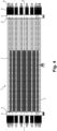
- an electrolyzer stack 1 extends longitudinally in a general direction A.
- the electrolyzer stack 1 comprises a block 2 of electrolytic cells which comprises at least two electrolytic cells which are mounted next to each other in the general direction A. Within the block 2, the electrolytic cells are mounted in parallel from a fluidic point of view and in series from a point of view electric.
- the electrolyzer stack 1 has two bottom plates 3 and 4.
- bottom plates 3 and 4 form supports between which the electrolytic cells are compressed so that the electrolyser stack 1 is waterproof and so that a good quality electrical contact is created inside the electrolytic cells.
- bottom plates 3 and 4 make it possible to support the forces generated by the pressure internal to block 2 as well as the forces external to block 2 necessary to ensure the compression of block 2.
- the bottom plates 3 and 4 can play the role of electrical conductor and current distributor.
- the electrolyzer stack 1 comprises a first distribution plate 5 associated with the first bottom plate 3 and a second distribution plate 6 associated with the second bottom plate 4. These are then the distribution plates 5 and 6 which will here play the role of electrical conductor and current distributor.
- the first distribution plate 5 (associated with the positive terminal) is arranged upstream of the block 2 and the second distribution plate 6 (associated with the negative terminal) is arranged downstream of said block 2.
- a first of the two distribution plates 5 is connected to the positive terminal of the electrolyzer stack 1. Then, a portion of the internal main face of the first bottom plate 3 (main face facing towards the block 2 and in particular the distribution plate 5) is covered with a pellet of electrically insulating material. Said portion is for example arranged in the center of said internal main face.
- the second of the two distribution plates 6 is connected to the negative terminal of the electrolyzer stack 1.
- the second bottom plate 4 will be at the same potential and also serves as a gateway for feeding an electrolytic solution and exhausting of this same solution charged with the gases formed during the electrolysis in block 2.
- holes are provided in said second bottom plate 4. Said holes often have a different section between the two main faces of the second bottom plate 4.
- the external main face that facing the outside of the block 2
- has one or two hole(s) for example cylindrical shapes
- two holes for discharging electrolytic reaction products in addition to the heated electrolytic solution.
- Three or four holes are drilled on the internal main face (opposite to the external main face) of said second bottom plate 4 for the same purpose, and for example oblong-shaped holes to improve the distribution or collection of fluids.
- the holes on the main external face are equipped with appropriate flanges for connecting the inlet and return pipes of the electrolytic solution.
- the electrolyzer stack 1 is here supplied with direct current.
- the first distribution plate 5 presents a potential of substantially 700 Volts while the second distribution plate 6 has a potential of 0 Volts.
- the electrolytic solution is supplied and evacuated at the level of the second distribution plate 6 and the second bottom plate 4, the distribution plate 6 having a potential of 0 Volt which avoids any current leakage (the potential of the second distribution plate 6 being that of the earth).
- seals are chosen from a material having an electrical resistance much greater than that of the electrolytic solution.
- the electrolyzer stack 1 includes an end joint (not visible in the figures) arranged between the first distribution plate 5 and the first bottom plate 3. Now the first bottom plate 3 is grounded so that the potential difference at said end joint reaches the same value as the voltage applied between the positive and negative terminals of the electrolyzer cell 1, for example, substantially 700 Volts.
- the first bottom plate 3 is electrically isolated from block 2.
- the electrolyzer stack 1 comprises a layer (not visible in the figures) of electrically insulating material, layer arranged between the first bottom plate 3 and the first distribution plate 5.
- the layer is for example an attached disc or a deposit made on the first bottom plate 3 and/or the first distribution plate 5.
- the electrolyzer stack 1 includes means for fixing the different electrolytic cells 10 together by common clamping.
- the fixing means comprise a plurality of tie rods 7.
- Each tie rod 7 extends rectilinearly in the electrolyzer stack 1.
- Each tie rod 7 thus extends longitudinally in the electrolyzer stack 1 parallel to the general direction A
- Each tie rod 7 is shaped like a rod.
- the tie rods 7 therefore all extend parallel to each other.
- the tie rods 7 are positioned around the perimeter of the different electrolytic cells. Preferably, the tie rods 7 are distributed all around the block 2 and preferably at a regular interval.
- the tie rods 7 extend through the bottom plates 3 and 4 of the electrolyzer stack 1, through specific holes in said bottom plates 3 and 4, and thus each have two ends external to the block 2.
- the tie rods 7 are partly covered with a sleeve of electrically insulating material. This helps prevent short circuits between the electrolytic cells in the event of contact or projection.
- the sleeve extends over the entire section of the tie rod 7 arranged between the two bottom plates 3 and 4.
- the ends of the tie rods 7 are threaded.
- the end threads are rolled threads.
- the rolled threads will have the advantage of making the machining of the tie rods 7 easier, particularly if the tie rods 7 are of a significant length and for example a length of several meters.
- the fixing means also include nuts 8 screwed onto the ends of the tie rods 7.
- the fixing means also include means for prestressing the two bottom plates 3 and 4 between them and therefore the different electrolytic cells between them.
- Said prestressing means also make it possible to absorb deformations and/or variations in thickness of the elements constituting the electrolyser stack 1, due to thermal expansion or variations in external and internal mechanical stresses to the electrolyser stack 1. (such as the internal pressure of the electrolyzer cell).
- the prestressing means are received on the ends of the tie rods 7 so as to be arranged, for a given end, between the nearest bottom plate (3 or 4) and the nuts 8 arranged on the same end.
- the fixing means include spring washers 9 such as Belleville washers.
- the spring washers 9 are received on the ends of the tie rods 7.
- the spring washers 9 are more precisely here arranged on each tie rod 7, at the level of the external part of said tie rod 7, when the latter has passed through the nearest bottom plate (3 or 4).
- the fixing means thus described allow the electrolyser stack 1 to cope in particular with thermal expansions and/or variations in mechanical stresses external and internal to the electrolyser stack 1 (such as for example the internal pressure in the electrolyser stack 1). electrolyzer).
- all the electrolytic cells of the electrolyzer stack 1 are identical to each other so that the following description of an electrolytic cell 10 is also applicable to the description of the other electrolytic cells 10.
- Such an electrolytic cell 10 comprises a central membrane 11 which is framed by two electrodes 12a and 12b (an anode and a cathode, respectively) which are themselves framed by two spacers 16 (or “flow field material” in English) which are themselves framed by two bipolar plates 14. Furthermore, the electrolytic cell 10 also includes a seal 13 (the existence of which has already been mentioned above) which is compressed between the two bipolar plates 14 of the electrolytic cell 10.
- the two bipolar plates 14 of an electrolytic cell 10 being identical to each other, the following description of one of the bipolar plates 14 is also applicable to the other of the bipolar plates 14 of the same electrolytic cell 10.
- the bipolar plate 14 is made of a material capable of enduring the corrosive environment reigning inside the electrolytic cell 10.
- the bipolar plate 14 is for example based on nickel and is for example made of nickel or nickel-plated carbon steel.
- the bipolar plate 14 is further shaped so as to have two main faces: a first main face facing the inside of the electrolytic cell 10 considered and a second main face facing the outside of the electrolytic cell 10 considered.
- the bipolar plates 14 are asymmetrical (according to a plane of symmetry passing through the center of the bipolar plate considered). Consequently, within the same electrolytic cell 10, the first face of the bipolar plate 14 which is being described faces a second face of another bipolar plate 14 identical to that which is in question. being described. Within block 2, all the bipolar plates 14 are oriented in the same way.
- the Z axis here coincides with the general direction A.
- the thickness of the bipolar plate 14 (along the Z axis) is less important than its other dimensions.
- the bipolar plate 14 is shaped so as to present a cross section (in an XY plane) in any geometric shape (square, rectangular, disc-shaped, etc.).
- the bipolar plate here has a disc cross section.
- the external periphery of the bipolar plate 14 is defined by a first zone 21, a second zone 22 and a third zone 23.
- the first zone 21 extends here over the entire circumference of at least one of the main faces of the bipolar plate 14.
- the first zone 21 is therefore a ring forming the external periphery of the main face.
- the first zone 21 makes it possible to improve the resistance to the internal pressure prevailing within the electrolytic cell 1 of the bipolar plate 14 and makes it possible to improve the sealing of the electrolytic cell 10 with respect to the outside of the electrolytic cell 1.
- said first zone 21 makes it possible to reinforce the resistance of the bipolar plate 14 in particular to the radial pressure loads exerted on the bipolar plate 14 (when the electrolytic cell 10 is arranged in the electrolytic cell 1).
- the first zone 21 is dimensioned to meet the standard applicable to pressure tanks and for example the PED 2014/68/EU standard.
- the first zone 21 is preferably textured.
- the first zone 21 has grooves, ridges, roughness, a rough appearance, etc. at least one of the main faces of the bipolar plate 14 and preferably at both faces. main parts of the bipolar plate 14.
- the circular edge of the bipolar plate 14 i.e. the surface connecting the two main faces of the bipolar plate 14 between them
- the circular edge of the bipolar plate 14 is very smooth, ie not textured.
- the second zone 22 also extends circumferentially so as to be bordered externally by the first zone 21.
- the second zone 22 is coaxial with the first zone 21.
- the second zone 22 extends here over the entire circumference of at least one of the main faces of the bipolar plate 14.
- the second zone 22 is therefore a ring.
- the second zone 22 is smooth , ie not textured.
- This second zone 22 is located around the electrolyte supply channels and the evacuation channels for gaseous products resulting from electrolysis.
- This second zone 22 is less thick (the thickness being considered along the Z axis) than the first zone 21.
- the bipolar plate 14 is shaped to present at least one shoulder between the first zone 21 and the second zone 22.
- the bipolar plate 14 is shaped to present two shoulders between the first zone 21 and the second zone 22. These two shoulders are identical here (as visible in the figure 3a ) and provided at the level of the two main faces of the bipolar plate 14.
- the bipolar plate 14 is thus symmetrical along a plane of central symmetry parallel to the axes X and Y at the level of its first zone 21 and its second zone 22.
- the narrowing between the first zone 21 and the second zone 22 makes it possible to achieve a different seal between the two zones.
- the third zone 23 also extends circumferentially so as to be bordered externally by the second zone 22.
- the third zone 23 is coaxial with the second zone 22.
- the third zone 23 extends here over the entire circumference of the bipolar plate.
- the third zone 23 is a ring.
- This third zone 23 is less thick (the thickness being considered along the Z axis) than the second zone 22.
- the bipolar plate 14 is shaped to present at least one shoulder between the second zone 22 and the third zone 23.
- the bipolar plate 14 is shaped to present a single shoulder between the second zone 22 and the third zone 23.
- This shoulder is provided at the level of the first main face of the bipolar plate 14, i.e. that facing the inside of the electrolytic cell 10. This shoulder allows the membrane 11 to be housed.
- the second zone 22 and the third zone 23 extend in the extension of one another at the level of the second main face of the bipolar plate 14.
- the second face of the bipolar plate 14 is devoid of such a shoulder so that the second face of the other bipolar plate of the electrolytic cell considered is devoid of such a shoulder.
- the membrane 11 is thus arranged between the two bipolar plates so as to fit only in the shoulder of one of the two bipolar plates 14.
- the bipolar plate 14 is thus asymmetrical according to a central plane of symmetry parallel to the axes figures 3a and 3b And 3c ).
- the third zone 23 is entirely smooth ( ie not textured) or partially smooth or entirely textured.
- the third zone 23 is textured at the level of the first main face of the bipolar plate 14. This facilitates holding the membrane 11 in place.
- the third zone 23 comprises grooves, striations, roughness, a rough appearance, etc.
- the third zone 23 is smooth at the level of the second main face of the bipolar plate 14. The thickness of the bipolar plate 14 (along the Z axis ) therefore decreases as the shoulders progress, at the junction between the first and second zones 21 and 22 but also between the second zone 22 and the third zone 23.
- the bipolar plate 14 is thus thicker at its first zone 21 than its second zone 22 than its third zone 23.
- the first zone 21, the second zone 22 and the third zone 23 jointly form a ring 25.
- the ring 25 thus forms the circumferential periphery of the bipolar plate 14.
- a central portion 24 of the bipolar plate 14 also extends so as to be bordered externally by the third zone 23.
- the central portion 24 is coaxial with the third zone 23.
- the central portion 24 is full.
- the central portion 24 thus forms a circular plate.
- This central portion 24 is less thick (the thickness being considered along the Z axis) than the third zone 23.
- the bipolar plate 14 is shaped to present at least one shoulder between the third zone 23 and the central portion 24.
- the bipolar plate 14 is shaped to present two shoulders between the third zone 23 and the central portion 24. These two shoulders are here identical and provided at the level of the two main faces of the bipolar plate 14.
- the central portion 24 can optionally itself have at least one shoulder so that its thickness (the thickness being considered along the Z axis) shrinks towards the center of the plate.
- the central portion 24 is therefore the thinnest part (the thickness being considered along the Z axis) of the bipolar plate 14.
- the central portion 24 can be smooth or textured.
- the central portion 24 plays the role of current collector and will transmit it to the spacers 16 which are on either side of it.
- the bipolar plate 14 has orifices 15 passing right through it. These orifices 15 are dedicated to the supply of electrolytic solution and the exhaust of electrolysis products.
- the bipolar plate 14 has between three and six orifices.
- the orifices are for example associated two by two, the pairs of two orifices being distributed homogeneously over the circumference of the bipolar plate 14.
- the bipolar plate can thus comprise three pairs of two orifices.
- At least one of the orifices 15 is provided in the second zone 22.
- all the orifices 15 are provided in the second zone 22.
- the orifices may have a circular, oblong, etc. cross section or another shape.
- at least one of the orifices 15 is of oblong cross section.
- the role of said central portion 24 is not really to support high pressure forces, unlike the crown 25.
- the central portion 24 thus mainly has the role of serving as a support for the components stacked within the cell. electrolytic 10, namely the spacers 16, the electrodes 12a and 12b and the membrane 11. The forces are therefore equal on the two faces of the central portion 24.
- the bipolar plates 14 therefore have a particular geometry.
- the thickness of each aforementioned zone varies from a few tenths of a millimeter to several millimeters.
- the thickness of a aforementioned zone also has a variable value under the effect of the thermal expansion of the bipolar plate 14 (the variability of the thickness of each zone due to thermal expansion thus also varying from one zone to one other).
- the two bipolar plates 14 compress a joint 13 between them.
- each bipolar plate 14 plays the role of cathode for an electrolytic cell 10 and anode for another electrolytic cell 10 immediately adjacent).
- the two bipolar plates 14 compress a single joint 13 between them.
- all the joints 13 of the electrolytic cells 10 are identical within the cell block 2 so that the following description of one of the joints 13 is also applicable to the other joints 13 of the other electrolytic cells 10.
- the main functionalities of the seal 13 are as follows: i) ensure the sealing of each electrolytic cell 10 with respect to the outside of the electrolyzer stack 1, ii) ensure the sealing of the channels conveying a gas which is generated within block 2 with respect to those carrying another gas generated within block 2, iii) ensuring the sealing of the chambers where the electrolysis reactions occur where the two aforementioned gases are generated to isolate them from from each other but also ensure sealing towards the channels mentioned just before, iv) act as an electrical insulation layer between two adjacent bipolar plates 14 and v) define the thickness to which the electrolytic cells 10 are compressed according to the direction Z.
- a single joint 13 is compressed between two adjacent bipolar plates 14 within the same electrolytic cell 10.
- the joint 13 is shaped so as to have a square or rectangular cross section (according to a transverse sectional plane).
- Joint 13 is therefore called a “flat joint”.
- the seal 13 is shaped correspondingly to the shape of the crown 25 of the associated bipolar plate 14.
- the joint 13 is generally shaped like a ring, the associated bipolar plate 14 being disc-shaped.
- joint 13 is pierced with a plurality of holes.
- the holes made in the seal 13 correspond to those made in zone 22 of the bipolar plate 14.
- the seal 13 is shaped to have a diameter (of its cross section) that is as constant as possible over all its internal and external circumferences and/or a thickness (along the Z axis) that is as constant as possible over its entire section (but also of 'one joint 13 to another).
- this makes it possible to have faces of the joint 13 parallel as possible to each other and to the main faces of the bipolar plates 14 facing each other.
- the tolerance on the dimensions of the seal 13 will depend on the application for which it is intended (for example the tolerance is +/-0.1 millimeter in thickness). As we have said, and as more visible at the figure 3c , the joint 13 is compressed between two adjacent bipolar plates 14 and more precisely between the two external peripheries of the main faces facing said bipolar plates 14 and more precisely between the two crowns 25 facing said bipolar plates 14.
- the bipolar plates 14 by compressing the joint 13, deform it in turn so as to delimit and characterize said joint 13 in three distinct portions.
- the diameter of the joint 13 (according to a cross section) is such that the joint 13 extends from the lateral edge of the bipolar plates 14 to the connection between the third zones 23 and the central portions 24 (preferably exceeding the third zones 23).
- each portion of the present seal 13 fulfills a distinct sealing function and is characterized by a specific compression level, the latter varying from one portion to another.
- the physical and mechanical consequence is the reduction in variable thickness of said seal 13 depending on the portion considered.
- the seal 13 is directly compressed between the first two zones 21 (without intermediate component).
- the seal 13 is directly compressed between the two second zones 22 (without intermediate component).
- the seal 13 is not directly compressed between the two third zones 23.
- the membrane 11 is also present between these two third zones 23. Consequently, the seal 13 is compressed on the one of its faces directly by one of the third zones 23 and on the other of its faces directly by the membrane 11 which is itself directly compressed by the third zone 23 of the bipolar plate 14 opposite.
- the seal 13 presents then a thickness significantly less than that of its second portion, the membrane 11 filling the rest of the space between the two third zones 23. The sealing of the membrane 11 is thus obtained.
- the seal 13 is thus distributed over its entire height (along the axis X) between its three portions and therefore between the three zones of the crowns 25.
- the part of the electrolytic cell 10 located at the level of the first zones 21 of the two bipolar plates 14 and the first portion of the seal 13 makes it possible to prevent the electrolyte solution or gases from leaving the electrolyzer stack 1 , in other words it is dedicated to ensuring the sealing of the electrolytic cell 10 with respect to the external environment. It ensures, for example, a seal greater than or equal to 10 -3 milligrams per meter per second - mg/(m*s) when the seal is measured using helium gas - and preferably a seal greater than or equal to at 10 -4 mg/(m*s).
- This first part is characterized by the presence of textures on the bipolar plates 14 in which the joint 13 is deformed.
- the seal 13 can, by deforming, fill the hollows of the first portions of the bipolar plates 14 and thus reinforce the sealing of the electrolytic cell 10.
- these textures constitute an additional obstacle to the gases and other substances present, to find the path towards the outside of the electrolyzer stack 1.
- This presence of textures also plays a role which promotes friction between the electrolytic cells 10 and therefore the self-maintenance of the plurality of cells electrolysis 10 stacked to form block 2. This advantage is reinforced when the block is horizontal in operation.
- the compression of the seal 13 is such that the seal 13 reaches at the level of the first part a maximum thickness (along the Z axis) of 94% and preferably 78% and preferably 75% of its thickness of departure (when it is in its resting state flat on a flat surface without external constraints).
- the starting thickness is for example equal to or greater than 3.0 millimeters. Preferably, this starting thickness does not exceed 3.5 millimeters.
- the second part of the electrolytic cell 10 located at the level of the second zones 22 of the two bipolar plates 14 and the second portion of the seal 13 makes it possible to avoid an exchange between the channels carrying hydrogen and oxygen in the electrolytic cell 10 or from the electrolytic cell 10 itself (from the third zone 23 and the central portion 24) towards these said channels.
- the compression of the seal 13 is such that the seal 13 reaches at the level of the second part a thickness (along the Z axis) of between 92 and 97% of its initial thickness (when it is in its rest state). flat on a flat surface without external constraints) and preferably a thickness of 92% of its initial thickness. In all cases, the seal 13 is less compressed than at the first part and therefore has a greater thickness than at the first part.
- the widening of the joint 13 between the first zones 21 and the second zones 22 make it possible to achieve a different seal between the first zones 21 and the second zones 22.
- the seal between the first zones 21 and the second zones 22 is of good quality.
- the third part of the electrolytic cell 10 located at the level of the third zones 23 of the two bipolar plates 14 and the third portion of the seal 13 makes it possible to accommodate the membrane 11 as has already been indicated.
- This third part therefore ensures sealing between the anode and cathode compartments of the electrolytic cell 10.
- the third portion of the seal 13 thus defines a third compression zone aimed at maintaining the membrane 11 and ensuring its tightness on its perimeter.
- the compression of the seal 13 is such that the seal 13 reaches at the level of the third part a thickness (along the Z axis) of between 86 to 92% of its initial thickness (when it is in its rest state). flat on a flat surface without external constraints) and preferably a thickness between 88 and 92% of its starting thickness and preferably a thickness of 90% of its starting thickness.
- the seal 13 is made of monomer material or of polymer material and for example of plastic material.
- the seal 13 is made of a material of the polytetrafluoroethylene or polytetrafluoroethene type (commonly abbreviated PTFE or better known under the trade name Teflon - registered trademark).
- PTFE polytetrafluoroethylene or polytetrafluoroethene type
- the material is made of or based on or of the polytetrafluoroethylene or polytetrafluoroethene type with the addition of at least one filler.
- the filler is fiberglass.
- said material is reinforced polytetrafluoroethylene.
- reinforced polytetrafluoroethylene is polytetrafluoroethylene reinforced with glass fibers or reinforced polytetrafluoroethene is polytetrafluoroethene reinforced with carbon fibers.
- the end seal arranged between the first distribution plate 5 and the first bottom plate 3 is in the same material as the seal 13 of an electrolytic cell 10 which has just been described.
- the end seal is for example identical to said seal 13.
- Said end seal is optionally made of monomer material or of polymer material and for example of plastic material.
- the layer of electrically insulating material between the first bottom plate 3 and the first distribution plate 5 is in the same material as the end joint arranged between the first distribution plate 5 and the first bottom plate 3
- the layer of electrically insulating material between the first bottom plate 3 and the first distribution plate 5 is in the same material as said seal 13.
- Said layer is optionally made of monomer or polymer material and for example of plastic material.
- the end seal arranged between the second distribution plate 6 and the second bottom plate 4 is in the same material as the seal 13 of an electrolytic cell 10 which has just been described.
- Said end seal is for example identical to said seal 13.
- Said end seal is optionally made of monomer material, of polymer material and for example of plastic material.
- the pellet arranged on the internal face of the first distribution plate 5 is a layer of material directly attached to the first distribution plate 5 or is formed by deposition of powder (by deposition of Halar (registered trademark) for example ).
- the electrolytic cell 10 thus described has very good sealing due to the specific compression of the seal 13 between the bipolar plates 14.
- the electrolytic cell 10 is made waterproof thanks to a single seal 13 and this with three zones of different tightness and compression.
- the use of a single seal 13 made of plastic material (and no longer made of elastomer as in the prior art) also makes it possible to improve the sealing of the electrolyzer cell.
- the seal 13 resists better, even over a long period, to the corrosive environment reigning inside the electrolyzer stack 1.
- the seal 13 is thus made of a hard material resistant to the strong mechanical compressions to which the electrolyzer stack is subjected.
- sub-assemblies are individually constructed, each sub-assembly being composed by assembling two spacers 16 and two electrodes 12a, 12b on either side of a bipolar plate 14. Each Strictly speaking, this subset constitutes two adjacent electrolytic half-cells.
- said subassemblies are stacked successively, separated from each other by a membrane 11 and a seal 13, forming said electrolytic cells 10 electrically connected in series.
- the last electrolytic cell 10 of one end of the block 2 is covered by the second distribution plate 6, itself covered by the second bottom plate 4 and the last electrolytic cell 10 of the other end of the block 2 is covered by the first distribution plate 5, itself covered by the first bottom plate 3, thus delimiting the electrolyzer stack 1.
- the newly assembled electrolyzer stack 1 is put into compression thanks to the tie rods 7, nuts 8 and spring washers 9.
- the electrolyzer stack 1 is pre-tightened (and therefore the different layers of the electrolytic cell 10 between them as well as the joints 13).
- This third step is preferably carried out at room temperature.
- this third step is carried out at a temperature between 15 and 25 degrees Celsius and for example between 18 and 22 degrees Celsius.
- Pre-tightening is obtained for example by acting on the nuts 8 of the tie rods 7.
- several nuts 8 are tightened simultaneously.
- the nuts 8 are all grouped by group, each group being tightened one after the other and the nuts within the same group being tightened simultaneously.
- the tightening of the groups is done in a staggered or star pattern. For example, we can tighten a group of nuts 8 at the same time, before moving on to the next group whose nuts are located as close as possible to the nuts of the first group 8, and so on. Preferably, during this phase all nuts 8 are tightened.
- Pre-tightening can be carried out for example by hydraulic means and for example hydraulic cylinders.
- the electrolyzer stack is tightened to reach a threshold characteristic of a targeted initial compression rate of at least one of the joints 13 and preferably of all the joints 13.
- the threshold can thus be a target thickness of at least one of the joints or even a target thickness of several joints or even a target thickness of the electrolyser stack 1 or even a target tightening force of the stack electrolyzer.
- we measure correspondingly during the first phase for example a thickness of at least one of the joints or even a thickness of the electrolyzer stack or even the tightening force applied to the electrolyzer stack.
- this third step includes a series of tightening sessions so that the tightening of the electrolyzer stack is carried out in stages.
- we estimate at the end of each level how far we are from the threshold to control the tightening force on the next level.
- the electrolyzer stack 1, and therefore the block 2 are then subjected to successive tightening cycles.
- a tightening cycle consists of the following phases.
- Heating of the electrolyzer stack 1 This first phase is carried out for example by injection of a gas or a liquid (such as steam, and for example water vapor, or a liquid hot, and for example hot water) through part of the inlet and outlet orifices of the bottom plate 4 to heat the entire interior of the electrolyzer stack 1, and in particular the joints 13.
- a gas or a liquid such as steam, and for example water vapor, or a liquid hot, and for example hot water
- the gas or the liquid may be at room temperature inside the electrolyzer cell.
- heating means may be temporarily introduced into the electrolyzer stack 1 in order to heat the gas or liquid (for example, the heating means may include one or more resistors).
- the heating means will be introduced temporarily into the electrolyzer stack 1 through the orifices 15 of the bipolar plates 14.
- Second phase Tightening the electrolyzer stack 1 (and therefore the different layers of the electrolytic cell 10 between them as well as the joints 13).
- Tightening is obtained for example by acting on the nuts 8 of the tie rods 7.
- several nuts 8 are tightened simultaneously.
- the nuts 8 are all grouped by group, each group being tightened one after the other and the nuts within the same group being tightened simultaneously.
- the tightening of the groups is done in a staggered or star pattern. For example, we can tighten a group of nuts 8 at the same time, before moving on to the next group whose nuts are located as close as possible to the nuts of the first group 8, and so on. Preferably, during this phase all nuts 8 are tightened.
- Tightening can be carried out for example by means of hydraulic means and for example hydraulic cylinders.
- This cooling can be natural (by stopping the heating of the electrolyzer stack 1, the latter being in contact with air at ambient temperature which will allow natural cooling thereof) and/or forced [for example by injection of a gas or a liquid (such as cold water) through part of the inlet and outlet orifices of the bottom plate 4 to cool the entire interior of the electrolyzer stack 1, and in particular the joints 13 / by ventilation / etc.].
- a gas or a liquid such as cold water
- This tightening is carried out like the second phase but at room temperature as in the third pre-tightening step (the temperature intervals indicated can also be applied here).
- the second phase (in particular during its first iteration if phases 1 to 4 are repeated several times) allows a significant reduction in the individual thickness of the different joints 13.
- Phases 1 to 4 are preferably repeated again until a threshold characteristic of a targeted final compression rate of at least one of the joints 13 and preferably of all the joints 13 is reached.
- the aforementioned threshold is linked to at least one compression rate of at least one of the joints 13 and preferably of all the joints 13.
- the aforementioned threshold is linked to at least the compression rate of the portion of at least one of the joints 13 (and preferably all the joints 13) linked to the first zones 21 of the facing bipolar plates 14. Even more precisely, the aforementioned threshold is linked to the compression rates, defined above in the application, linked to the different portions of at least one of the joints and preferably of all the joints 13.
- the joints 13 have a thickness close to their target value.
- the following iterations thus aim more at the disappearance of the plastic behavior of the joints in their area of use.
- At least one parameter is measured among the following parameters: a thickness of at least one of the joints, a thickness of the electrolyzer stack or of the block, a distance between the bottom plates 3 and 4, a clamping force applied to the electrolyzer stack.
- the thickness of all the joints 13 is estimated by measuring the distance between the bottom plates 3 and 4 or the tightening force applied to the electrolyzer stack 1.
- the final threshold is a target thickness value of the electrolyzer stack 1.
- the thickness of the electrolyzer stack 1 we measure the thickness of the block 2 by measuring the thickness between the bottom plates 3 and 4 at different points on the circumference of block 2; then we average the different values obtained obtain an average thickness of block 2; from the number of cells and the thickness of the different elements per cell we deduce the average thickness of each of the joints 13).
- the fourth step is implemented so that this ratio is maintained within a given range throughout the fourth step.
- Hn+1/Hn ratio of less than 0.5 (meaning that the thickness delta has been reduced by more than 50%) and preferably less than 0.4 ( meaning that the thickness delta has been reduced by more than 60%).
- Hn+1/Hn ratio of between 0.5 and 0.25 and preferably between 0.4 and 0.25.
- the first role and/or the second role are also implemented for the third pre-tightening step.
- the heating of the joint 13 is done by steam (by steaming).
- steam by steaming
- the thickness of the seal 13 is reduced permanently to reach the predefined compression rates.
- the plastic behavior (or creep) of said joint 13 is attenuated over the course of hot tightening cycles and at room temperature until a range of elastic behavior is reached. In this way, the joint 13 presents at the end of this fourth step a linear deformation behavior. The latter makes it possible (thanks to the counter-balancing force induced by the elastic washers 9) to ensure sealing for the different zones of the bipolar plates 14, particularly in view of the expansions and the pressure forces applied to the electrolyzer stack 1.
- the thickness (along the Z axis) of the joint 13 is therefore gradually but drastically reduced by plastic deformation of said joint 13.
- figure 5 allows you to visualize this reduction in thickness of the joint 13 during the different stages and phases of the assembly process described.
- the curve thus illustrates the evolution of the average thickness of the joint 13 (determined as indicated above or by another method) during the different stages and phases of the assembly process described, the value 100% corresponding to the reduction target thickness.
- the thickness of the joint 13 is reduced by at least 10% or even by at least 15% or even by at least 20% or even by at least 25%. This makes it possible to limit the creep of the joints 13 during the actual operation of the electrolyzer stack 1.
- the seals 13 ensure very good sealing to the electrolyzer stack 1, even over time on a scale of 10 or 20 years.
- part of the tightening is carried out hot, which allows you to benefit from the softer (less hard) nature of the material of the seal 13 at high temperatures.
- Such an assembly with thick distribution plates 5 and 6 and thin and flat bipolar plates 14 allows homogeneity of the current in all the electrolytic cells 10 of the electrolyzer stack 1 while the voltage is different at the terminals of each electrolytic cell 10 and that the current is only connected to one or more points at the periphery of each distribution plate 5 and 6.
- the bipolar plates 14 are parallel to each other within the block 2 thanks to their particular shape and the good tightening of each joint 13. This further improves the homogeneity of the current in all the electrolytic cells 10.
- the temperature and pressure prevailing inside the electrolyzer stack 1 may change but the joints will advantageously always remain in the elastic range obtained.
- the nominal operating point of the battery of electrolyzer is for example 85 degrees Celsius under 3 Megapascals.
- the assembly process described will advantageously apply to all types of electrolyzer stack 1, regardless of their thermal and mechanical characteristics, their number, their size or the nature of the material constituting said electrolyzer stack 1.
- the end seal(s) may be different from the seals 13.
- the electrolyzer stack 1 could be assembled differently from what has been described.
- the electrolytic cell can be cooled so that its temperature is less than 35 degrees Celsius and for example between 15 and 35 degrees Celsius and for example between 20 and 35 degrees Celsius.
- the cold re-tightening can thus be carried out at a different temperature between two successive cold re-tightenings (provided that the electrolytic cell is at a temperature lower than that of the hot re-tightening and close to the ambient temperature without preferentially falling below 15 ° degrees Celsius which could hinder the plasticity of the joint material) and/or at a different temperature than the first tightening phase.
- the electrolysis cell can be used horizontally, vertically or in any other position.
- the electrolysis cell can be assembled horizontally, vertically or in any other position.
- the electrolysis cell will be assembled vertically and used horizontally.
Landscapes
- Chemical & Material Sciences (AREA)
- Engineering & Computer Science (AREA)
- Chemical Kinetics & Catalysis (AREA)
- Electrochemistry (AREA)
- Materials Engineering (AREA)
- Metallurgy (AREA)
- Organic Chemistry (AREA)
- Inorganic Chemistry (AREA)
- Electrolytic Production Of Non-Metals, Compounds, Apparatuses Therefor (AREA)
Priority Applications (2)
| Application Number | Priority Date | Filing Date | Title |
|---|---|---|---|
| EP22200480.6A EP4353872A1 (de) | 2022-10-10 | 2022-10-10 | Bipolarplatte, elektrolysezelle, elektrolyseurzelle und montageverfahren dafür |
| PCT/EP2023/078088 WO2024079141A1 (fr) | 2022-10-10 | 2023-10-10 | Plaque bipolaire, cellule electrolytique, pile d'electrolyseur et procede d'assemblage associes |
Applications Claiming Priority (1)
| Application Number | Priority Date | Filing Date | Title |
|---|---|---|---|
| EP22200480.6A EP4353872A1 (de) | 2022-10-10 | 2022-10-10 | Bipolarplatte, elektrolysezelle, elektrolyseurzelle und montageverfahren dafür |
Publications (1)
| Publication Number | Publication Date |
|---|---|
| EP4353872A1 true EP4353872A1 (de) | 2024-04-17 |
Family
ID=83689659
Family Applications (1)
| Application Number | Title | Priority Date | Filing Date |
|---|---|---|---|
| EP22200480.6A Pending EP4353872A1 (de) | 2022-10-10 | 2022-10-10 | Bipolarplatte, elektrolysezelle, elektrolyseurzelle und montageverfahren dafür |
Country Status (2)
| Country | Link |
|---|---|
| EP (1) | EP4353872A1 (de) |
| WO (1) | WO2024079141A1 (de) |
Citations (8)
| Publication number | Priority date | Publication date | Assignee | Title |
|---|---|---|---|---|
| GB1145751A (en) * | 1965-04-01 | 1969-03-19 | John Thomson Anderson | An electrolyser cell and frame and a method of making the same |
| US4758322A (en) * | 1985-07-17 | 1988-07-19 | Metkon S.A. | Apparatus for the electrolysis of solutions |
| US20100187102A1 (en) * | 2008-12-23 | 2010-07-29 | Schmitt Edwin W | Universal cell frame for high-pressure water electrolyzer and electrolyzer including the same |
| US20130140171A1 (en) * | 2008-07-15 | 2013-06-06 | Next Hydrogen Corporation | Electrolyser module |
| US10494729B2 (en) * | 2014-12-18 | 2019-12-03 | Commissariat A L'energie Atomique Et Aux Energies Alternatives | Elementary unit for reactor performing water electrolysis or co-electrolysis (SOEC) or fuel cell (SOFC) operating under pressure |
| CN112969822A (zh) * | 2018-08-20 | 2021-06-15 | 泰利斯纳诺能量公司 | 用于制备高压且高纯度的气态氢的模块化电解单元 |
| US11108061B2 (en) * | 2017-05-15 | 2021-08-31 | Commissariat A L'energie Atomique Et Aux Energies Alternatives | Water electrolysis or co-electrolysis reactor (SOEC) or fuel cell (SOFC) for pressurized operation and with a clamping system suitable for such operation |
| JP2022081854A (ja) * | 2020-11-20 | 2022-06-01 | 森村Sofcテクノロジー株式会社 | 電気化学反応セルスタックの製造方法 |
-
2022
- 2022-10-10 EP EP22200480.6A patent/EP4353872A1/de active Pending
-
2023
- 2023-10-10 WO PCT/EP2023/078088 patent/WO2024079141A1/fr unknown
Patent Citations (8)
| Publication number | Priority date | Publication date | Assignee | Title |
|---|---|---|---|---|
| GB1145751A (en) * | 1965-04-01 | 1969-03-19 | John Thomson Anderson | An electrolyser cell and frame and a method of making the same |
| US4758322A (en) * | 1985-07-17 | 1988-07-19 | Metkon S.A. | Apparatus for the electrolysis of solutions |
| US20130140171A1 (en) * | 2008-07-15 | 2013-06-06 | Next Hydrogen Corporation | Electrolyser module |
| US20100187102A1 (en) * | 2008-12-23 | 2010-07-29 | Schmitt Edwin W | Universal cell frame for high-pressure water electrolyzer and electrolyzer including the same |
| US10494729B2 (en) * | 2014-12-18 | 2019-12-03 | Commissariat A L'energie Atomique Et Aux Energies Alternatives | Elementary unit for reactor performing water electrolysis or co-electrolysis (SOEC) or fuel cell (SOFC) operating under pressure |
| US11108061B2 (en) * | 2017-05-15 | 2021-08-31 | Commissariat A L'energie Atomique Et Aux Energies Alternatives | Water electrolysis or co-electrolysis reactor (SOEC) or fuel cell (SOFC) for pressurized operation and with a clamping system suitable for such operation |
| CN112969822A (zh) * | 2018-08-20 | 2021-06-15 | 泰利斯纳诺能量公司 | 用于制备高压且高纯度的气态氢的模块化电解单元 |
| JP2022081854A (ja) * | 2020-11-20 | 2022-06-01 | 森村Sofcテクノロジー株式会社 | 電気化学反応セルスタックの製造方法 |
Also Published As
| Publication number | Publication date |
|---|---|
| WO2024079141A1 (fr) | 2024-04-18 |
Similar Documents
| Publication | Publication Date | Title |
|---|---|---|
| EP2193226B1 (de) | Hochtemperaturelektrolysator mit wasserstoffrückgewinnungsvorrichtung | |
| EP3625846B1 (de) | Wasser-elektrolysereaktor oder -koelektrolysereaktor (soec) oder brennstoffzelle (sofc) betrieben bei hohem druck beinhaltend eine einspannvorrichtung geeignet für diesen betrieb | |
| EP1866990B1 (de) | Polymermembran-brennstoffzelle | |
| FR2923654A1 (fr) | Pile a combustible comportant une pluralite de cellules elementaires connectees en serie par les collecteurs de courant. | |
| FR2491957A1 (fr) | Ensemble de cellules electrochimiques et procede pour y reduire le courant de fuite | |
| WO2016096752A1 (fr) | Motif elementaire pour reacteur d'electrolyse ou de co-electrolyse de l'eau (soec) ou pile a combustible (sofc) a fonctionnement sous pression | |
| EP2545208A1 (de) | Aufbau eines hochtemperaturelektrolysators mit hoher zielproduktion durch eine elektrolysezelle und begrenzter zellabbaurate | |
| EP3012892B1 (de) | Elektrochemische Anordnung zum Stapeln | |
| EP3476977B1 (de) | Reversible wiederholende einheit von wasser elektrolyse oder co-elektrolyse (soec) oder einer brennstoffzelle, die unter druck oder entkoppelter druckspannung arbeitet | |
| EP4353872A1 (de) | Bipolarplatte, elektrolysezelle, elektrolyseurzelle und montageverfahren dafür | |
| EP4353873A1 (de) | Verfahren zum verbinden eines stapels von elementen miteinander | |
| CA3126965C (fr) | Reacteur d'electrolyse ou de co-electrolyse (soec) ou pile a combustible (sofc) a empilement de cellules electrochimiques par modules preassembles, procede de realisation associe | |
| EP3871284A1 (de) | Elektrochemisches festoxidsystem mit integrierten heizmitteln | |
| FR3023981A1 (fr) | Plaque bipolaire pour reacteur electrochimique a zone d'homogeneisation compacte et a faible differentiel de pression | |
| WO2017060267A1 (fr) | Systeme d'electrolyse de l'eau (soec) ou pile a combustible (sofc) a fonctionnement sous pression dont la regulation est amelioree | |
| BE1027327B1 (fr) | Compresseur a etat solide et procede pour fournir une contre-pression sur un empilement de cellules de compresseur a l'etat solide | |
| EP1220346A1 (de) | Verbund-Grundelement und seine Dichtung für eine Brennstoffzelle und Verfahren zur Herstellung dieser Einheit | |
| EP3098889B1 (de) | Stromzuführungsvorrichtung zu einem elektrolysegerät oder einer hochtemperatur-brennstoffzelle | |
| FR2980306A1 (fr) | Procede de test d'etancheite d'une structure bipolaire pour generateur electrochimique | |
| FR2977725A1 (fr) | Procede de realisation d'un joint d'etancheite entre des composants d'une pile a combustible et procede de fabrication d'une pile a combustible correspondant | |
| WO2014060198A1 (fr) | Pile a combustible amelioree | |
| WO2022101569A1 (fr) | Dispositif de serrage pour un empilement electrochimique, et assemblage forme par le dispositif de serrage et l'empilement electrochimique | |
| FR2902938A1 (fr) | Procede de realisation des connexions electriques d'un ensemble de stockage d'energie electrique | |
| EP4092163B1 (de) | Anordnung aus einem festoxidstapel vom typ soec/sofc und einem dichten hochtemperatur-kupplungssystem mit kupplungsflansch | |
| FR2964393A1 (fr) | Electrolyseur a haute temperature (eht) a surete de fonctionnement amelioree |
Legal Events
| Date | Code | Title | Description |
|---|---|---|---|
| PUAI | Public reference made under article 153(3) epc to a published international application that has entered the european phase |
Free format text: ORIGINAL CODE: 0009012 |
|
| STAA | Information on the status of an ep patent application or granted ep patent |
Free format text: STATUS: THE APPLICATION HAS BEEN PUBLISHED |
|
| AK | Designated contracting states |
Kind code of ref document: A1 Designated state(s): AL AT BE BG CH CY CZ DE DK EE ES FI FR GB GR HR HU IE IS IT LI LT LU LV MC ME MK MT NL NO PL PT RO RS SE SI SK SM TR |